Submittal Transmittal Alley 111 Apartments Project ... Library... · Submittal Transmittal Alley...
41
Detailed, Grouped by Each Number Submittal Transmittal Skanska USA Building Inc. Alley 111 Apartments Project # 4212049-000 Tel: Fax: Date: 11/4/2013 Reference Number: 0005 Transmitted To: Transmitted By: Albert Martin Kevin Reed GGLO Skanska USA Building Inc. 1301 First Avenue Suite 301 Seattle, WA 98101 Tel: (206) 467-5828 929 109th Ave NE Bellevue, WA 98004 Submittal Package No Description Due Date Package Action Qty 11/18/2013 Facility Natural Gas Piping 0011 - 224900 - 0 1 Transmitted For Delivered Via Tracking Number Email Approval Notes Item Action Items Description Qty 0001 Facility Natural Gas Piping Product Data-Piping 0002 Facility Natural Gas Piping Product Data-Valves 0003 Facility Natural Gas Piping Product Data-Hangers and Supports Contact Name Copies Notes Company Name Cc: Remarks Please see the attached submittal for your review. Signature Signed Date Prolog Manager Printed on: 11/4/2013 6WEST Page 1
Transcript of Submittal Transmittal Alley 111 Apartments Project ... Library... · Submittal Transmittal Alley...

Detailed, Grouped by Each Number
Submittal Transmittal
Skanska USA Building Inc.Alley 111 Apartments Project # 4212049-000
Tel: Fax:
Date: 11/4/2013 Reference Number: 0005
Transmitted To: Transmitted By: Albert MartinKevin Reed
GGLO Skanska USA Building Inc.1301 First Avenue Suite 301Seattle, WA 98101Tel: (206) 467-5828
929 109th Ave NEBellevue, WA 98004
Submittal Package No Description Due Date Package ActionQty
11/18/2013Facility Natural Gas Piping0011 - 224900 - 01
Transmitted For Delivered Via Tracking Number
EmailApproval
Notes Item ActionItems DescriptionQty
0001 Facility Natural Gas Piping Product Data-Piping
0002 Facility Natural Gas Piping Product Data-Valves
0003 Facility Natural Gas Piping Product Data-Hangers and Supports
Contact Name Copies NotesCompany NameCc:
Remarks
Please see the attached submittal for your review.
Signature Signed Date
Prolog Manager Printed on: 11/4/2013 6WEST Page 1

SKANSKA USA BUILDING INC.Date Rec'd To Arch From Arch Returned
REVIEWED CORRECTIONS NOTED REVISE AND RESUBMIT
This submittal REVIEW shall not be construed as a Complete check and indicates only that information presented conforms Generally to the Contract Documents. In no case is Subcontractor or Supplier Relieved of full responsibility for adherence to the Contract Document and Satisfactory construction of all work. Submitted to Owner, Architect-Engineer for final approval.
Name: Date:Submittal #:
Albert Martin
10/29/2013 10/29/2013
✔
SMTL#0011-224900-0-HawkMech-Facility Natural Gas
11/4/2013
11/4/2013 11/4/2013
kevinr
Submittal
kevinr
Typewritten Text
x
kevinr
Text Box
See following pages for Rushing response memo.

SUBMITTAL REVIEW COVERSHEET
Project Name: Alley 111 1725 Westlake Avenue N.
Date: 2013-11-12 Suite 300
Submittal No &
Description
Submittal #0011-224900-0 – Natural Gas Materials Seattle, WA 98109
206-285-7100
Submittal Date: 2013-11-05
Submittal Status:
No Exception Taken (NET)
Exception Taken as Noted, Provide Revised Submittal for Project Records, No Add’l Rushing Review Req’d (ET)
Exception Taken as Noted, Revise and Resubmit as Noted for Rushing Review (ET-RR)
Revision History: Rev 0 Date: 2013-11-12 By: Steven Huff E-mail: [email protected]
Comments:
Status
0-1 No exception taken with submitted products unless specifically noted below. INFO
0-2
Quick Disconnect – the submitted Dormont product is for indoor use only. Provide
submittal for quick disconnect device listed for use both indoor and outdoor OR provide
additional submittal for product rated for outdoor use.
ET-RR
0-3 Weatherproof vent cap – Product has not been included in submittal. Provide product
submittal for review. ET-RR
0-4
Gas Pressure Regulator: Specify which model(s) will be provided, including orifice size
and spring range.
Provide with vent limiter where regulators are to be installed in corridors.
ET-RR
0-5
Sage Prime Gas Flow Meters: No exception taken with submitted products. Ensure that
meters are purchased with any accessories required to be compatible with building BMS
system.
NET
END OF REVIEW
Review is only for general conformance with the project design concepts and general compliance
with the information given in the contract documents. The contractor remains responsible for full
compliance with the contract drawings and specifications, confirmation of all project specific
dimensions, fabrication processes, techniques of construction, coordination of work with that of all
other trades, and the satisfactory performance of their work.

Section Sub-Section Tag Description Manufacturer Model # Approval Status Submitted
224900
224900 2.1 A - Steel Pipe: Black Steel, Schedule 40 Various A53 ERW, Grade B, Black Pending Review 11/1/2013
224900 2.1 A-1 - Malleable-Iron Threaded Fittings Various Class 150 Malleable Pending Review 11/1/2013
224900 2.1 A-2 - Wrought-Steel Welding Fittings Various A234 WBP - Standard Wall Weld Pending Review 11/1/2013
224900 2.1 A-3 - Unions Various Class 150 Malleable Pending Review 11/1/2013
224900 2.1 A-4 - Forged Steel Flanges and Flanged Fittings Various Class 125 Slip on and Weld Neck Pending Review 11/1/2013
224900 2.1 B - Corrugated Stainless Steel Tubing N/A Not used on this project Pending Review 11/1/2013
224900 2.2 A - Appliance Flexible Connectors BrassCraft Model CSSB Stainless Coated Pending Review 11/1/2013
224900 2.2 B - Quick-Disconnect Devices Dormont SnapFast Quick Disconnect Pending Review 11/1/2013
224900 2.2 C - Y-Pattern Strainers Mueller Model 11M Pending Review 11/1/2013
224900 2.2 D - Basket Strainers N/A Not used on this project Pending Review 11/1/2013
224900 2.2 E - Waterproof Vent Cap Hawk Field Fabricated Pending Review 11/1/2013
224900 2.3 - Ball Valves (Gas Cock) Nipco T-585-70-UL Pending Review 11/1/2013
224900 2.3-A - Solenoid Valves ASCO Model 8210 Pending Review 11/1/2013
224900 2.3-B - Solenoid Valve Timer Intermatic Model EI200 Pending Review 11/1/2013
224900 2.4 - Pressure Reducing Valves Sensys Model 243 Pending Review 11/1/2013
224900 2.5 - Earthquake Valve Pacific Seismic Model 315F Pending Review 11/1/2013
224900 2.6 GM-1 Gas Sub-Meter: Hydronic Boilers Sage Thermal Mass Flow Meter Pending Review 11/1/2013
224900 2.6 GM-2 Gas Sub-Meter: Domestic Boilers Sage Thermal Mass Flow Meter Pending Review 11/1/2013
224900 2.6 GM-3 Gas Sub-Meter: AHU Sage Thermal Mass Flow Meter Pending Review 11/1/2013
224900 2.6 GM-FUTURE Gas Sub-Meter: TI Space N/A N/A - By Tenant per P4.01 Pending Review 11/1/2013
224900 2.7 - Steel Pipe Sleeves Hawk Fabricated A53 ERW Galv Pending Review 11/1/2013
224900 2.8 - Mechanical Sleeve Seals 3M Multiple Pending Review 11/1/2013
224900 2.9 - Labeling and Identifying Brady Multiple Pending Review 11/1/2013
Facility Natural Gas Piping
Hawk Mechanical
10/30/2013
Submittal Log - Hawk Job #: 1651
Alley 111
Submittal Status

SUBMITTAL DATA Rev. 04/27/05
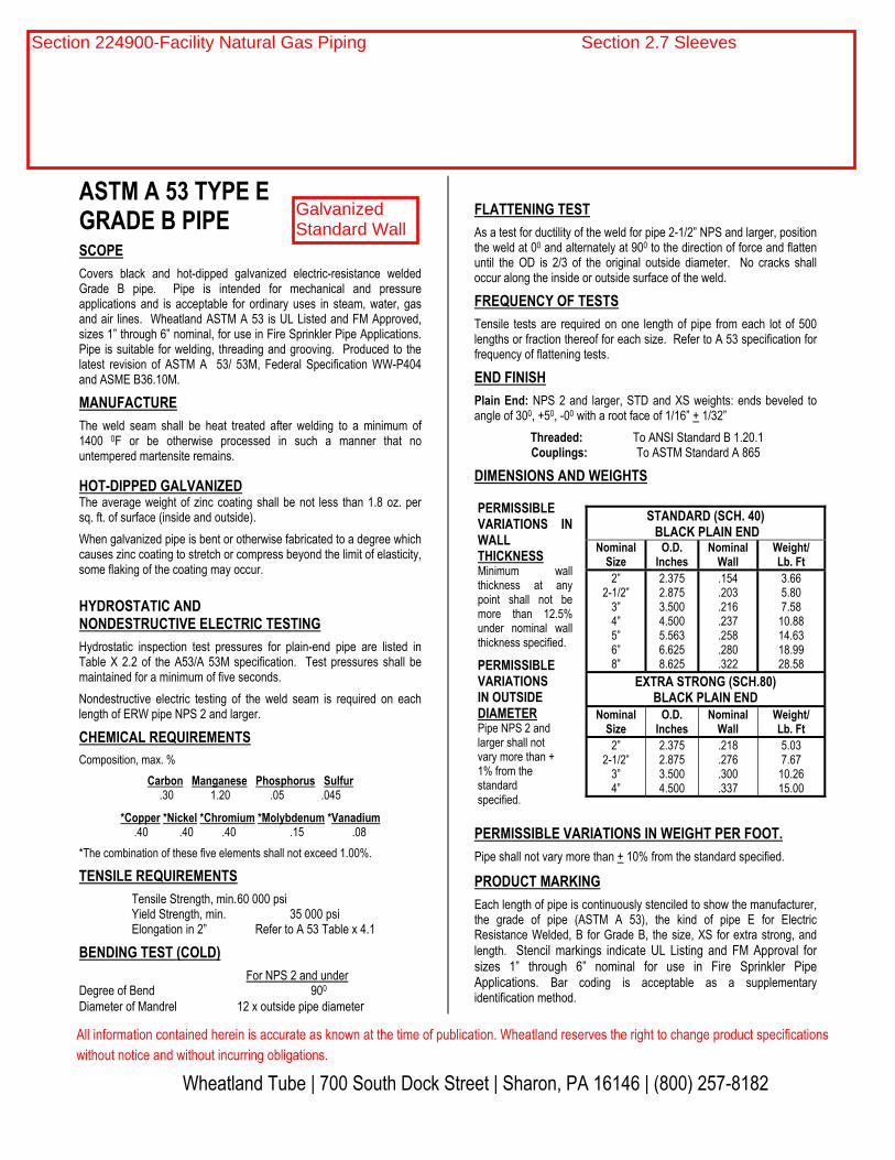
ASTM A 53 TYPE E GRADE B PIPE
SCOPE
Covers black and hot-dipped galvanized electric-resistance weldedGrade B pipe. Pipe is intended for mechanical and pressureapplications and is acceptable for ordinary uses in steam, water, gasand air lines. Wheatland ASTM A 53 is UL Listed and FM Approved,sizes 1” through 6” nominal, for use in Fire Sprinkler Pipe Applications.Pipe is suitable for welding, threading and grooving. Produced to thelatest revision of ASTM A 53/ 53M, Federal Specification WW-P404 and ASME B36.10M.
MANUFACTURE
The weld seam shall be heat treated after welding to a minimum of1400 0F or be otherwise processed in such a manner that nountempered martensite remains.
HOT-DIPPED GALVANIZED The average weight of zinc coating shall be not less than 1.8 oz. persq. ft. of surface (inside and outside).
When galvanized pipe is bent or otherwise fabricated to a degree whichcauses zinc coating to stretch or compress beyond the limit of elasticity,some flaking of the coating may occur.
HYDROSTATIC AND NONDESTRUCTIVE ELECTRIC TESTING
Hydrostatic inspection test pressures for plain-end pipe are listed inTable X 2.2 of the A53/A 53M specification. Test pressures shall bemaintained for a minimum of five seconds.
Nondestructive electric testing of the weld seam is required on eachlength of ERW pipe NPS 2 and larger.
CHEMICAL REQUIREMENTS
Composition, max. %
Carbon Manganese Phosphorus Sulfur.30 1.20 .05 .045
*Copper *Nickel *Chromium *Molybdenum *Vanadium .40 .40 .40 .15 .08
*The combination of these five elements shall not exceed 1.00%.
TENSILE REQUIREMENTS
Tensile Strength, min.60 000 psiYield Strength, min. 35 000 psiElongation in 2” Refer to A 53 Table x 4.1
BENDING TEST (COLD)
For NPS 2 and underDegree of Bend 900
Diameter of Mandrel 12 x outside pipe diameter
FLATTENING TEST
As a test for ductility of the weld for pipe 2-1/2” NPS and larger, positionthe weld at 00 and alternately at 900 to the direction of force and flattenuntil the OD is 2/3 of the original outside diameter. No cracks shalloccur along the inside or outside surface of the weld.
FREQUENCY OF TESTS
Tensile tests are required on one length of pipe from each lot of 500lengths or fraction thereof for each size. Refer to A 53 specification for frequency of flattening tests.
END FINISH
Plain End: NPS 2 and larger, STD and XS weights: ends beveled toangle of 300, +50, -00 with a root face of 1/16” + 1/32”
Threaded: To ANSI Standard B 1.20.1 Couplings: To ASTM Standard A 865
DIMENSIONS AND WEIGHTS
STANDARD (SCH. 40) BLACK PLAIN END
Nominal ize S
O.D. Inches
Nominal Wall
Weight/ Lb. Ft
2”2-1/2”
3”4”5”6”8”
2.3752.8753.5004.5005.5636.6258.625
.154
.203
.216
.237
.258
.280
.322
3.665.807.58
10.8814.6318.9928.58
EXTRA STRONG (SCH.80) BLACK PLAIN END
Nominal Size
O.D. Inches
Nominal Wall
Weight/ Lb. Ft
2”2-1/2”
3”4”
2.3752.8753.5004.500
.218
.276
.300
.337
5.037.67
10.2615.00
PERMISSIBLE VARIATIONS IN WEIGHT PER FOOT.
Pipe shall not vary more than + 10% from the standard specified.
PRODUCT MARKING
Each length of pipe is continuously stenciled to show the manufacturer,the grade of pipe (ASTM A 53), the kind of pipe E for ElectricResistance Welded, B for Grade B, the size, XS for extra strong, andlength. Stencil markings indicate UL Listing and FM Approval forsizes 1” through 6” nominal for use in Fire Sprinkler PipeApplications. Bar coding is acceptable as a supplementaryidentification method.
PERMISSIBLE VARIATIONS IN WALL THICKNESSMinimum wallthickness at anypoint shall not bemore than 12.5%under nominal wallthickness specified.
PERMISSIBLE VARIATIONS IN OUTSIDE DIAMETER Pipe NPS 2 and larger shall not vary more than + 1% from the standardspecified.
All information contained herein is accurate as known at the time of publication. Wheatland reserves the right to change product specifications without notice and without incurring obligations.
Wheatland Tube | 700 South Dock Street | Sharon, PA 16146 | (800) 257-8182
Section 224900-Facility Natural Gas Piping Section 2.1-A - Steel Pipe
Black,Standard Wall

Section 224900-Facility Natural Gas Piping Section 2.1A-1 Fittings

Hydronic Piping Section: 232113Section 224900-Facility Natural Gas Piping Section 2.1A-2 Weld Fittings

WARD UNION BRASS TO IRON SEAT CLASS 150
WARD UNION BRASS TO IRON SEAT CLASS 250
WARD UNION BRASS TO IRON SEAT CLASS 300
NPSOverallLengthA (min)
Length ofThreadsB (min)
ThruHole
C (min)
Width of Nut
D (min)
1/8 1.26 0.30 0.21 0.93
1/4 1.44 0.32 0.36 1.10
3/8 1.61 0.36 0.52 1.26
1/2 1.72 0.43 0.61 1.45
3/4 1.94 0.50 0.80 1.71
3/4 X 1/2 1.94 0.50 0.80 1.71
1 2.06 0.58 1.00 2.07
1 1/4 2.26 0.67 1.31 2.50
1 1/2 2.41 0.70 1.55 2.82
2 2.75 0.75 2.03 3.41
2 1/2 3.22 0.92 2.38 4.12
3 3.50 0.98 3.00 4.75
*4 3.85 1.08 4.03 6.00
NPSOverall Length A (min)
Length of Threads B (min)
Thru Hole
C (min)
Width of Nut
D (min)
1/8 1.26 0.30 0.21 0.93
1/4 1.55 0.43 0.30 1.11
3/8 1.71 0.47 0.42 1.26
1/2 1.18 0.57 0.54 1.45
3/4 2.07 0.64 0.74 1.71
1 2.31 0.75 0.95 2.07
1 1/4 2.62 0.84 1.27 2.57
1 1/2 2.78 0.87 1.50 2.89
2 3.31 1.00 1.93 3.48
2 1/2 3.52 1.17 2.32 4.15
3 3.84 1.23 2.90 4.69
*4 4.39 1.33 3.82 6.47
NPSOverall Length A (min)
Length of Threads B (min)
Thru Hole
C (min)
Width of Nut
D (min)
1/8 1.26 0.30 0.21 1.26
1/4 1.55 0.43 0.30 1.55
3/8 1.71 0.47 0.42 1.71
1/2 1.81 0.57 0.54 1.81
3/4 2.12 0.64 0.74 2.12
1 2.31 0.75 0.95 2.31
1 1/4 2.66 0.84 1.27 2.66
1 1/2 2.85 0.87 1.50 2.85
2 2.23 1.00 1.93 3.23
2 1/2 3.33 1.17 2.320 3.33
3 4.09 1.23 2.90 4.09
4 — — — —
*UL Standards not applicable to 4” size union
*UL Standards not applicable to 4” size union
D
B
B
A
C
B
B
A
D
C
C
A
B
B
D
25
Section 224900-Facility Natural Gas Piping Section 2.1A-3 Unions

CLASS 150 STEEL PIPE FLANGES
87
TEL: 708/594-1700 FAX: 708/458-0106 www.weldbend.com
Copyright © 2010 by Weldbend Corporation. All Rights Reserved.
FLANGES
Pipe Size
Outside Diameter
of Flange
Thickness of
Flange (Min.)
Thickness of
Lap Joint (Min.)
Diameter of
Hub *
Diameter of
Weld Neck
Length Through Hub
Thread Length (Min.)
Bore
Lap Joint Radius
Depth of
Socket
Threaded, Slip-on
& Socket Weld
Lap Joint
Weld Neck
Slip-on & Socket
Weld (Min.)
Lap Joint
(Min.)
Weld Neck & Socket Weld
O.D. C C W K Y2 Y3 Y1 T B2 B3 B1 J D
ASME B16.5
½ 3.50 0.38 0.44 1.19 0.84 0.56 0.62 1.81 0.62 0.88 0.90 0.62 0.12 0.38
¾ 3.88 0.44 0.50 1.50 1.05 0.56 0.62 2.00 0.62 1.09 1.11 0.82 0.12 0.44
1 4.25 0.50 0.56 1.94 1.32 0.62 0.69 2.12 0.69 1.36 1.38 1.05 0.12 0.50
1 ¼ 4.62 0.56 0.62 2.31 1.66 0.75 0.81 2.19 0.81 1.70 1.72 1.38 0.19 0.56
1 ½ 5.00 0.62 0.69 2.56 1.90 0.81 0.88 2.38 0.88 1.95 1.97 1.61 0.25 0.62
2 6.00 0.69 0.75 3.06 2.38 0.94 1.00 2.44 1.00 2.44 2.46 2.07 0.31 0.69
2 ½ 7.00 0.81 0.88 3.56 2.88 1.06 1.12 2.69 1.12 2.94 2.97 2.47 0.31 0.75
3 7.50 0.88 0.94 4.25 3.50 1.12 1.19 2.69 1.19 3.57 3.60 3.07 0.38 0.81
3 ½ 8.50 0.88 0.94 4.81 4.00 1.19 1.25 2.75 1.25 4.07 4.10 3.55 0.38
4 9.00 0.88 0.94 5.31 4.50 1.25 1.31 2.94 1.31 4.57 4.60 4.03 0.44
5 10.00 0.88 0.94 6.44 5.56 1.38 1.44 3.44 1.44 5.66 5.69 5.05 0.44
6 11.00 0.94 1.00 7.56 6.63 1.50 1.56 3.44 1.56 6.72 6.75 6.07 0.50
8 13.50 1.06 1.12 9.69 8.63 1.69 1.75 3.94 1.75 8.72 8.75 7.98 0.50
10 16.00 1.12 1.19 12.00 10.75 1.88 1.94 3.94 1.94 10.88 10.92 10.02 0.50
12 19.00 1.19 1.25 14.38 12.75 2.12 2.19 4.44 2.19 12.88 12.92 12.00 0.50
14 21.00 1.31 1.38 15.75 14.00 2.19 3.12 4.94 2.25 14.14 14.18 13.25 0.50
16 23.50 1.38 1.44 18.00 16.00 2.44 3.44 4.94 2.50 16.16 16.19 15.25 0.50
18 25.00 1.50 1.56 19.88 18.00 2.62 3.81 5.44 2.69 18.18 18.20 17.25 0.50
20 27.50 1.62 1.69 22.00 20.00 2.81 4.06 5.62 2.88 20.20 20.25 19.25 0.50
24 32.00 1.81 1.88 26.12 24.00 3.19 4.38 5.94 3.25 24.25 24.25 23.25 0.50
WN BLD ASME B16.47 Series A
30 38.75 2.88 2.88 30.75 30.00 5.32
36 46.00 3.50 3.50 36.75 36.00 6.13
42 53.00 3.75 3.75 43.00 42.00 6.69
48 59.50 4.19 4.19 49.12 48.00 7.50
WN BLD ASME B16.47 Series B
30 34.94 1.69 1.94 31.00 30.06 3.88
36 41.62 2.00 2.25 37.19 36.06 4.57
42 48.25 2.25 2.65 43.38 42.12 5.19
48 54.81 2.50 3.00 48.50 48.12 5.82
6. Thread standards on page 156.
7. Blind �anges may be produced with or without hubs.
8. All �anges conform to ASTM A105/ASME SA105.
9. All �anges ½"-24" conform to ASME B16.5.
All �anges 30" and larger conform to ASME B16.47.
* A taper shall not exceed 7 degrees on threaded, slip-on and lapped �anges.
Dimensions listed for socket weld and weld neck �anges are for Standard
bore unless speci!ed by purchaser.
NOTES1. Standard �ange facings on page 146.
2. All dimensions are in inches.
3. Calculated �ange weights on page 99.
4. For dimensional tolerances see page 144.
5. Weld end preparations on page 154.
For Ring Type Joint Facing Dimension information see page 148.
Section 224900-Facility Natural Gas Piping Section 2.1A-4 - Flanges

���������������� �����������
������������������� ��������������������������� ����������������������������������� ��������
�� ��������� ������������ ������������������ ������������������������������������!"��� ����������������������#����� ����� ������������������������������������� �������� ������������ ������� ������������������ ������ ����������������#������������������������������������������������ �����
����������
����� ���� �� ���
� �� ���������� �
�������� ��������������
$�����%�����&� � �������
$���%�� �����&� � '�������������$�(����%�����&� � )�������
$ ����%������*���&� +������������� � � ������
������,��#��� � ������������������������ � -���% ���.�����&�
,����/������� � �������� ����
�������� ��������� ��
$�0� � � /�������� �
$�� ��� � � �������(�1����� � ����� ����
����� � � ������������������ � � 0�������0��� �
����� � � �������� ���
������������2� �����,��� ����������������������
��������������������3����� �
����������
'���������������1����/������
�� ���������� ��� ���� ���� �������
45!67� 5������8�� 5!� !�����
45!65� 9������8�� 5!� :������
45!6!� ;������8��� 5!� 5!������
45!64� 56������8��� !9� 4<�������
45!69� 4!������8��� 5!� 9=������
���� ������������
>�����0�$��?*��� ���9�<=� � 0������65 -��(����� ������?���� � ������������9=@�/����5!7@�/���>#� � ����(���� ������
�������5!7�������/��������� ��+��������.�)������%������
0�������&���A�����0�������3��8��0����1������������
�������0�������0���.�$�� ��� ������������8���������������������!"��
�
5=B!==7�
������������������ ������
�������?������ )�*����� � 5=�===�����
� ���� � �4�===�����2 ������?����� �7=@����9==@�/�
?*�����,���2� � A�����5!7�������������� � � �3��5!7������9� ������
$������ � ��������0 ���)��� � !�������� � ��������
������� �� ���
������������ ��������������C����������������������� ��������������������� ������ ��������? �3����
��������� ���������� ������������ ��0������������� ����� �����������3������� ��� �������
������������ �
?���������������������������������������������� �������������������������������� �� � ���� ����������
������������������������������,��+�2�A0D���������
���������#�����)�*����0���� ��E��������'��������,����������������������#���8������������������#�� � ���
E����������������� ��������������,��+�2�?DA0D�D>�2F���+2$1+D?��EDD���A2��/�?D$�'��/��'1),?D+����
�?������ �������������� ������ �������� ������
/��� ��������������� ��������5�4=4�6!4�7:56���))D�2���
E�7�
Section 231123 - Natural Gas Piping 2.3 - Joining MaterialsSection 224900-Facility Natural Gas Piping Section 2.1A-d - Sealant

Visit www.oatey.com for updates
TECHNICAL SPECIFICATION: Oatey Yellow Gas Line Thread Seal Tape with Polytetrafluoroethylene (PTFE) is a thread
sealing tape designed specifically for gas lines up to 1-½” diameter. Yellow Gas Line Tape is a thick, full density thread sealing tape. Yellow Gas Line Thread Seal Tape is compatible with a broad range of gases and liquids, as well as compatible with many piping materials.
YELLOW GAS LINE THREAD
SEAL TAPE WITH PTFE
COMMON APPLICATIONS
Oatey Yellow Gas Line Thread Seal Tape with PTFE can be used on galvanized steel, iron, brass, copper,
aluminum, stainless steel, polyethylene, polypropylene, PVC, CPVC, ABS and fiberglass threaded piping. This
product is compatible with piping carrying dilute acids, compressed air, aliphatic solvents, dilute caustics, cutting
oils, diesel fuel oil, hydraulic fluids, L.P. Gas, Natural Gas, petroleum solvents, steam, vegetable oils, water and
many more.
NOT FOR USE ON LINES CARRYING OXYGEN.
Consult Oatey Technical Department for applications not specifically referenced above.
INGREDIENTS
99.5% PTFE 0.5% Pigment
When used for the intended end use application, this product is considered an “article” as defined in
OSHA 29 CFR 1910.1200(c).
APPROVALS AND LISTINGS
Meets Military Specification MIL-T-27730A, UL 31 RO, AGA 3226 and CAN/ULC-S642.
PRODUCT NUMBER DESCRIPTION PACK CARTON WEIGHT
31403 ½” X 260” Yellow PTFE Thread Seal Tape 100 7 lbs.
31403D ½” X 260” Yellow PTFE Thread Seal Tape – Display
20 1 lb.
10/2005
PHYSICAL/CHEMICAL PROPERTIES
Appearance Yellow Tape Density 1.25 to 1.5 g/c3
Pressure Rating* 10,000 psi Temperature Range -450° F to 500° F
Tensile Strength 1245 to 2500 psi Thickness 0.0032” TO 0.0038”
Shelf Life Indefinite *Pressure rating is relative to the torque and quality of the threads and the amount of tape used.
DIRECTIONS FOR USE
For threads up to 1-½” diameter, use ½” width of thread
seal tape. Clean the male and female threads of any oil or dirt. Apply the thread seal tape a minimum of three wraps,
using care to wrap in the direction of the thread rotation. Be sure to keep tension on the tape while wrapping. Do
not overlap the tape on the ends of the fitting.
PRECAUTIONS
Read all cautions and directions carefully before using this
product. Store spool in clean place and keep cover on the spool when not in use.
K-23
Section 231123 - Natural Gas Piping 2.3 - Joining MaterialsSection 224900-Facility Natural Gas Piping Section 2.1A-d - Sealant

This specification and all information contained herein is the confidential and exclusive property of BrassCraft Manufacturing, and shall not be disclosed to others without the written consent of BrassCraft. This specification must be returned to BrassCraft if requested.
300.01 CSSB Coated Gas Connectors REV 8/09 2009 Brass-Craft Mfg.
Pro
du
ct S
ub
mitta
l Fo
rm
CSSB 3/4” ID (7/8” OD) Coated Gas Appliance Connectors
Use: For use with indoor and outdoor connections of gas appliances to gas piping system. May be used with natural, manufactured, mixed and liquefied petroleum (LP or propane) gases and LP gas-air mixtures
Design Features:
Superior corrosion resistance to harsh chemicals found in common household
cleaning, plumbing repair and masonry products.
UV rays & salt resistant, ProCoat connectors are certified for indoor & outdoor use.
Greater strength & flexibility with greater depth & number of corrugations to withstand greater torque & bend cycles
Outperforms industry standards for torsion (1.5X) without compromising the
integrity of the coating or connector
Outperforms industry standard for repeated bending (2X) without compromising the integrity of the coating or connector
One-piece construction has no soldered of brazed joints
Smoother, burnished flare on connector ends seal with less torque
Uniform coat over entire length of connector for complete corrosion
resistance of the stainless steel core
100% leak tested
Operating Specifications:
Temperature: -40° to 150° F
Pressure: standard line pressures up to 1/2 psi maximum
CONNECTOR FLOW CAPACITY (Straight Length)
12” 18” 24” 30” 36” 48” 60” 72”
BTU per Hour (NG) 290,900 290,900 290,900 270,500 255,900 215,000 197,400 173,900
BTU per Hour (LPG) 465,440 465,440 465,440 432,800 409,440 344,000 315,840 278,240
Watts per Hour (NG) 85,254 85,254 85,254 79,276 74,997 63,010 57,852 50,965
MATERIAL SPECIFICATIONS
Tubing 304L stainless steel
Coating Polymer blend
Nuts C36000 Brass
Fittings C36000 Brass
For Residential and Commercial Applications
Job Name Engineer / Architect
Job Location Wholesaler
Submittal Date Contractor
Section 224900-Facility Natural Gas Piping Section 2.2-A Flex Connector

This specification and all information contained herein is the confidential and exclusive property of BrassCraft Manufacturing, and shall not be disclosed to others without the written consent of BrassCraft. This specification must be returned to BrassCraft if requested.
300.01 CSSB Coated Gas Connectors REV 8/09 2009 Brass-Craft Mfg.
Pro
du
ct S
ub
mitta
l Fo
rm
CSSB 3/4” ID (7/8” OD) Coated Gas Appliance Connectors
Part Listing:
CSSB1212-24 3/4” ID (7/8” OD) with 1” MIP x 1” MIP fittings x 24” length
CSSB1412-12 3/4” ID (7/8” OD) with 1” FIP x 1” MIP fittings x 12” length
CSSB1412-18 3/4” ID (7/8” OD) with 1” FIP x 1” MIP fittings x 18” length
CSSB1412-24 3/4” ID (7/8” OD) with 1” FIP x 1” MIP fittings x 24” length
CSSB1412-36 3/4” ID (7/8” OD) with 1” FIP x 1” MIP fittings x 36” length
CSSB1412-48 3/4” ID (7/8” OD) with 1” FIP x 1” MIP fittings x 48” length
CSSB11-12 3/4” ID (7/8” OD) with 3/4” MIP x 3/4” MIP fittings x 12" length
CSSB11-18 3/4” ID (7/8” OD) with 3/4” MIP x 3/4” MIP fittings x 18" length
CSSB11-24 3/4” ID (7/8” OD) with 3/4” MIP x 3/4” MIP fittings x 24" length
CSSB11-30 3/4” ID (7/8” OD) with 3/4” MIP x 3/4” MIP fittings x 30" length
CSSB11-36 3/4” ID (7/8” OD) with 3/4” MIP x 3/4” MIP fittings x 36" length
CSSB11-48 3/4” ID (7/8” OD) with 3/4” MIP x 3/4” MIP fittings x 48" length
CSSB11-60 3/4” ID (7/8” OD) with 3/4” MIP x 3/4” MIP fittings x 60" length
CSSB21-12 3/4” ID (7/8” OD) with 3/4” FIP x 3/4” MIP fittings x 12" length
CSSB21-18 3/4” ID (7/8” OD) with 3/4” FIP x 3/4” MIP fittings x 18" length
CSSB21-24 3/4” ID (7/8” OD) with 3/4” FIP x 3/4” MIP fittings x 24" length
CSSB21-24 P 3/4” ID (7/8” OD) with 3/4” FIP x 3/4” MIP fittings x 24" length, bagged
CSSB21-24 X 3/4” ID (7/8” OD) with 3/4” FIP x 3/4” MIP fittings x 24" length, bagged with cutcase
CSSB21-30 3/4” ID (7/8” OD) with 3/4” FIP x 3/4” MIP fittings x 30" length
CSSB21-36 3/4” ID (7/8” OD) with 3/4” FIP x 3/4” MIP fittings x 36" length
CSSB21-36 P 3/4” ID (7/8” OD) with 3/4” FIP x 3/4” MIP fittings x 36" length, bagged
CSSB21-36 X 3/4” ID (7/8” OD) with 3/4” FIP x 3/4” MIP fittings x 36" length, bagged with cutcase
CSSB21-48 3/4” ID (7/8” OD) with 3/4” FIP x 3/4” MIP fittings x 48" length
CSSB21-60 3/4” ID (7/8” OD) with 3/4” FIP x 3/4” MIP fittings x 60" length
CSSB21-72 3/4” ID (7/8” OD) with 3/4” FIP x 3/4” MIP fittings x 72" length
CSSB22-12 3/4 ”ID (7/8” OD) with 3/4” FIP x 3/4” FIP fittings x 12” length
CSSB22-18 3/4 ”ID (7/8” OD) with 3/4” FIP x 3/4” FIP fittings x 18” length
CSSB22-24 3/4 ”ID (7/8” OD) with 3/4” FIP x 3/4” FIP fittings x 24” length
CSSB22-30 3/4 ”ID (7/8” OD) with 3/4” FIP x 3/4” FIP fittings x 30” length
CSSB22-36 3/4 ”ID (7/8” OD) with 3/4” FIP x 3/4” FIP fittings x 36” length
CSSB22-48 3/4 ”ID (7/8” OD) with 3/4” FIP x 3/4” FIP fittings x 48” length
CSSB22-60 3/4 ”ID (7/8” OD) with 3/4” FIP x 3/4” FIP fittings x 60” length
CSSB22-72 3/4 ”ID (7/8” OD) with 3/4” FIP x 3/4” FIP fittings x 72” length
B
A
Section 224900-Facility Natural Gas Piping Section 2.2-A Flex Connector

This specification and all information contained herein is the confidential and exclusive property of BrassCraft Manufacturing, and shall not be disclosed to others without the written consent of BrassCraft. This specification must be returned to BrassCraft if requested.
300.01 CSSB Coated Gas Connectors REV 8/09 2009 Brass-Craft Mfg.
Pro
du
ct S
ub
mitta
l Fo
rm
CSSB 3/4” ID (7/8” OD) Coated Gas Appliance Connectors
PART DIMENSIONS ( Inches )
Connector Length – Nut by Nut
Series DIM. 12” 18” 24” 30” 36” 48” 60” 72”
CSSB A 10.00 16.00 22.00 28.00 34.00 46.00 58.00 70.00
PART DIMENSIONS ( Inches )
Connector Lengths - with Fittings
Model DIM. 12” 18” 24” 30” 36” 48” 60” 72”
CSSB1412 B 12.00 / 14.00
18.00 / 20.00
24.00 / 26.00
30.00 / 32.00
36.00 / 38.00
48.00 / 50.00
60.00 / 62.00
72.00 / 74.00
CSSB21 B 12.00 / 14.00
18.00 / 20.00
24.00 / 26.00
30.00 / 32.00
36.00 / 38.00
48.00 / 50.00
60.00 / 62.00
72.00 / 74.00
CSSB22 B 12.00 / 14.00
18.00 / 20.00
24.00 / 26.00
30.00 / 32.00
36.00 / 38.00
48.00 / 50.00
60.00 / 62.00
72.00 / 74.00
CSSB11 B 12.00 / 14.00
18.00 / 20.00
24.00 / 26.00
30.00 / 32.00
36.00 / 38.00
48.00 / 50.00
60.00 / 62.00
72.00 / 74.00
Listings & Certifications:
CSA listed to ANSI Z21.24 / CSA 6.10 standard “Connectors for Gas Appliances” (file #204593) CSA listed to ANSI Z21.75 / CSA 6.27 standard “Connectors for Outdoor Gas Appliances & Manufactured
Homes” (file #204593) The Commonwealth of Massachusetts
Country of Origin: Tubing made in China. Nuts, fittings and coating are made in the USA. Connector coated and assembled in the USA.
Section 224900-Facility Natural Gas Piping Section 2.2-A Flex Connector

The Dormont Blue Hose®
Stainless Steel ConstructionStainless Steel Braid Blue PVC Coating
(Cutaway shown)
FeaturesSnapFast® One-Handed Quick-Disconnect
Quick-Disconnect .................... Brass body, aluminum collar Thermal Shut-off ..................... Shuts off gas when internal temperatures exceed 350°F (177ºC)
Additional Components Restraining Device .................. PVC coated, steel multi-strand cable and mounting hardware Valve ................................... Full port, brass body
Elbow ................................... Malleable iron
*Deluxe Kits Include ..................... The Dormont Blue Hose, valve, restraining device, elbows, SnapFast, display box
SpecificationsThe Dormont Blue Hose®
Tubing ................................... Annealed, 304 stainless steel Braiding .................................. Multi-strand, 304 stainless steel wire Coating ................................... Blue antimicrobial PVC, melts at 350ºF (177ºC); coating will not hold a flame
End Fittings ............................. Carbon steel; zinc trivalent chromate
Stress Guard® ......................... 360º rotational end fitting at both ends
Approvals & CertificationsNSF/ANSI 169 – Special-purpose food equipment and devicesANSI Z21.69 / CSA 6.16 – Connectors for moveable gas appliancesANSI Z21.41 / CSA 6.9 – Quick-disconnect devices for use with gas fuel appliancesANSI Z21.15 / CSA 9.1 – Manually operated gas valves for appliances, appliance connectorsMeets requirements of ANSI Z223.1 / NFPA 54 National Fuel Gas CodeNot for use in temperatures less than 32°F (0°C). For indoor use only. Max operating pressure 1/2 psi.Refer to the catalog for additional approvals and certifications or go to www.dormont.com.
A restraining device is required for all moveable gas equipment.
Stress Guard®
Rotation Technology Reduces Stress at Both Ends of the Hose
SnapFast® One-handedQuick-Disconnect
Job Name _______________________________________Job Location ______________________________________Engineer ________________________________________Approval _________________________________
Contractor _______________________________________Approval ________________________________________Contractor's P.O. No. _______________________________Representative ____________________________________SKU _____________________________________________
For Commercial Applications
SnapFast® Quick-Disconnect AssembliesSizes: ½" to 1¼" (15 to 32mm)SnapFast Quick-Disconnect Assemblies feature flexible movement and the one-handed quick-disconnect fitting with a unique thermal shut-off design that automatically shuts off the gas when the internal temperature exceeds 350°F (177°C).
The Dormont Safety System™ is the first and only complete gas equipment connection system specifically engineered for the commercial kitchen. The Safety System consists of the famous Dormont Blue Hose and a variety of accessories
designed for improved safety and performance in commercial kitchens. Because they are manufactured in the USA under an ISO qualified production process and to multiple design certifications, you can Connect with Confidence with the Dormont Safety System.
Stress Guard®
Rotation Technology Reduces Stress at Both Ends of the Hose
Section 224900-Facility Natural Gas Piping Section 2.2-B Quick Disconnect

SnapFast® Quick-Disconnect Deluxe Kit Assembly
Ordering Information
Configuration Size I.D. 24" (607mm) 36" (914mm) 48" (1,219mm) 60" (1,524mm) 72" (1,829mm)
Deluxe Kit* 1650KIT24 1650KIT36 1650KIT48 1650KIT60 1650KIT72Basic Kit** ½" (15mm) 1650BPQR24 1650BPQR36 1650BPQR48 1650BPQR60 1650BPQR72 Hose Assembly*** 1650BPQ24 1650BPQ36 1650BPQ48 1650BPQ60 1650BPQ72
Deluxe Kit* 1675KIT24 1675KIT36 1675KIT48 1675KIT60 1675KIT72Basic Kit** ¾" (20mm) 1675BPQR24 1675BPQR36 1675BPQR48 1675BPQR60 1675BPQR72Hose Assembly*** 1675BPQ24 1675BPQ36 1675BPQ48 1675BPQ60 1675BPQ72
Deluxe Kit* 16100KIT24 16100KIT36 16100KIT48 16100KIT60 16100KIT72Basic Kit** 1" (25mm) 16100BPQR24 16100BPQR36 16100BPQR48 16100BPQR60 16100BPQR72Hose Assembly*** 16100BPQ24 16100BPQ36 16100BPQ48 16100BPQ60 16100BPQ72
Deluxe Kit* 16125KIT24 16125KIT36 16125KIT48 16125KIT60 16125KIT72Basic Kit** 1¼" (32mm) 16125BPQR24 16125BPQR36 16125BPQR48 16125BPQR60 16125BPQR72Hose Assembly*** 16125BPQ24 16125BPQ36 16125BPQ48 16125BPQ60 16125BPQ72
Product Part Numbers
LENGTH
Model Size I.D. 24" (607mm) 36" (914mm) 48" (1,219mm) 60" (1,524mm) 72" (1,829mm)
1650BPQ ½" (15mm) 87,000 77,000 68,000 60,000 55,000
1675BPQ ¾" (20mm) 232,000 218,000 180,000 158,000 139,000
16100BPQ 1" (25mm) 414,000 379,000 334,000 294,000 279,000
16125BPQ 1¼" (32mm) 699,000 615,000 541,000 476,000 419,000
BTU/hr Flow Capacity Natural Gas (Flow rating BTU/hr 0.64 SP. GR. @ 0.5 inch WC pressure drop)
The Dormont Blue Hose®
The Dormont Blue Hose is a commercial, moveable-grade gas connector designed for use with moveable equipment.
Moveable equipment is defined in ANSI Standard Z21.69/CSA 6.16 as gas utilization equipment that may be mounted on casters or otherwise be subject to movement.
GAS C
ONNECTOR
WAR RA N T Y
Limited
See catalog for detailsLIFETIME We guarantee our commercial gas connectors for the
life of the original appliance to which it is connected.
• One-handed quick-disconnect fitting• Thermal shut-off when internal temperature exceeds 350°F (177°C)
Typical Installation
USA: Export, PA • Tel. (724) 733-4800 • Fax: (724) 733-4808 • www.dormont.comA Watts Water Technologies Company
ES-D-SnapFastQD 1205 © 2012 Dormont
Restraining Device• ANSI Z21.69 Standard section 1.7.4 states: Connectors when used on caster-mounted equipment shall be installed with a restraining device, which prevents transmission of the strain to the connector
* Deluxe Kits include: The Dormont Blue Hose and restraining device, full port valve and (2) street elbows**Basic Kits include: The Dormont Blue Hose and restraining device, street elbow and SnapFast***Hose Assemblies include: The Dormont Blue Hose, SnapFast and street elbow
Section 224900-Facility Natural Gas Piping Section 2.2-B Quick Disconnect

Typical Service • Used extensively to strain foreign matter from pipe lines and provide economical protection
for costly pumps, meters, valves and other similar mechanical equipment.
Features• Machined seats in both body and cap align and lock the screen in place to stop sediment
bypass.
Construction• Gasketed cap is used for easy disassembly and assembly. Many others use Loctite, rendering
disassembly virtually impossible.
Self-Cleaning • Self cleaning is accomplished by opening the plug or valve connected to the blowoff outlet.
Blowoff Outlets• Outlets are NPT Tapped
• Sizes of tapping specified on the next page.
• Not normally furnished with plug. Plug available, specify with order.
Capacity• Generously proportioned bodies
• Open Area Ratio much greater than pipe size, ensure low pressure loss.
Pressure DropPressure Drop Charts in Technical Data section of Mueller Steam Specialty Engineering binder.
ES-MS-11M
Cast Iron Screwed End Y Strainers Sizes: 1⁄4"- 4" (6-100mm)
Model: 11M
Model 11M
11M Class 250
Pressure/Temperature –Non-ShockModel Material Rating11M Cast Iron 400psi @ -20°F to 150°F 27.58 bar @ 65.56°C 250psi @ 406°F 17.24 bar @ 207.78°C
Job Name ––––––––––––––––––––––––––––––––––––––––––– Contractor ––––––––––––––––––––––––––––––––––––––––––––
Job Location ––––––––––––––––––––––––––––––––––––––––– Approval –––––––––––––––––––––––––––––––––––––––––––––
Engineer ––––––––––––––––––––––––––––––––––––––––––––– Contractor’s P.O. No. ––––––––––––––––––––––––––––––––––
Approval ––––––––––––––––––––––––––––––––––––––––––––– Representative ––––––––––––––––––––––––––––––––––––––––
Material11M
Body Cast Iron ASTM A126-BGasket Metal filled Graphite
ScreensSTANDARD(WATER) STEAMRECOMMENDATION
MODEL SIZES MATERIAL OPENING MATERIAL OPENING
11M 1⁄2" - 2" 304SS 20 mesh 304SS 30 mesh11M 21⁄2"- 4" 304SS .062 perf 304SS .045 perf
Section 231123 - Natural Gas Piping 2.2 - Wye-StrainersSection 224900-Facility Natural Gas Piping Section 2.2 C - Strainers

Model 11M
A
B
C
Model 11BC
A
B
C
Dimensions and Weights
SIZE DIMENSIONS WEIGHTS A B C in. mm in. mm in. mm in. mm lbs. kgs.
1⁄4 6 33⁄16 81 21⁄16 52 1⁄4 6 1.6 0.7 3⁄8 10 33⁄16 81 21⁄16 52 1⁄4 6 1.6 0.7 1⁄2 15 33⁄16 81 21⁄16 52 1⁄4 6 1.6 0.7 3⁄4 20 33⁄4 95 27⁄16 61 3⁄8 10 2.4 1.1 1 25 4 102 25⁄8 66 3⁄8 10 3.0 1.4 11⁄4 32 5 127 33⁄8 85 3⁄4 20 5.2 2.3 11⁄2 40 53⁄4 146 37⁄8 98 3⁄4 20 8.0 3.6 2 50 7 177 43⁄4 121 1 25 12.5 5.7 21⁄2 65 91⁄4 234 57⁄8 149 11⁄2 40 22.0 10.0 3 80 10 254 6 152 11⁄2 40 30.0 13.6 4 100 153⁄16 386 111⁄4 286 11⁄2 40 70.0 32.0
Apply For Certified Drawings.
ES-MS-11-M 1020 © 2010 Mueller Steam Specialty
Mueller Steam Specialty product specifications in U.S. customary units and metric are approximate and are provided for reference only. For precise measure-ments, please contact Mueller Steam Specialty Technical Service. Mueller Steam Specialty reserves the right to change or modify product design, construction, specifications, or materials without prior notice and without incurring any obligation to make such changes and modifications on Mueller Steam Specialty products previously or subsequently sold.
A Watts Water Technologies Company USA:St.Pauls,NC•Tel.1-800-334-6259•Fax1-800-421-6772•www.muellersteam.com
Section 231123 - Natural Gas Piping 2.2 - Wye-StrainersSection 224900-Facility Natural Gas Piping Section 2.2 C - Strainers
NIBCO INC. WORLD HEADQUARTERS • 1516 MIDDLEBURY ST. • ELKHART, IN 46516-4740 • USA • PH: 1.800.234.0227 TECH SERVICES PH: 1.888.446.4226 • FAX: 1.888.336.4226 • INTERNATIONAL OFFICE PH: +1.574.295.3327 • FAX: +1.574.295.3455
www.nibco.com22
A H E A D O F T H E F L O W®
www.nibco.com
DezincificationResistant
Bronze Ball ValvesTwo-Piece Body • Full Port ¹⁄₄"-1" • Conventional Port 1¹⁄₄"-3" • Bronze Trim • Blowout-Proof Stem • UL Listed
250 PSI/17.2 Bar Non-Shock LP Gas per UL842
CONFORMS TO MSS SP-110 • CSA CERTIFIED TO ANSI/ASME B 16.33 AND CGA 3.16 FOR NATURAL AND PROPANE GAS TO 125 PSIG (¹⁄₄"-1")
MATERIAL LIST PART SPECIFICATION 1. Handle Nut Zinc Plated Steel 2. Handle Zinc Plated Steel Clear Chromate Plastisol Coated 3. Threaded Pack Gland Brass ASTM B 16 Alloy C36000 4. Packing PTFE 5. Stem Silicon Bronze ASTM B 371 Alloy C69430 or ASTM B 99 Alloy C65100 6. Thrust Washer Reinforced PTFE 7. Ball Brass ASTM B 124 Alloy C37700 or ASTM B16 Alloy C36000 EACH with Hard Chrome Plate 8. Seat Ring (2) Reinforced PTFE 9. Body Bronze ASTM B 584 Alloy C84400 10. Body End Piece Bronze ASTM B 584 Alloy C84400
DIMENSIONS—WEIGHTS—QUANTITIES Dimensions T-585-70-UL Size A B C D T-580-70-UL Master In. mm. In. mm. In. mm. In. mm. In. mm. Lbs. Kg. Ctn. Qty. †¹⁄₄ 8 2.00 51 1.75 44 5.00 127 .38 10 .45 .21 100 † ³⁄₈ 10 2.00 51 1.75 44 5.00 127 .38 10 .45 .20 100 † ¹⁄₂ 15 2.44 62 1.88 48 5.19 132 .50 13 .64 .29 100 † ³⁄₄ 20 2.94 75 2.25 57 6.25 159 .75 19 1.33 .60 50 †1 25 3.34 85 2.38 60 6.44 164 1.00 25 1.79 .81 40 1 ¹⁄₄ 32 3.94 100 2.63 67 6.75 171 1.00 25 2.17 .98 20 1 ¹⁄₂ 40 4.31 109 3.00 76 8.88 226 1.25 32 3.27 1.48 20 2 50 4.63 118 3.16 80 9.06 230 1.50 38 5.09 2.31 10 2 ¹⁄₂ 65 5.84 148 3.50 89 9.66 245 2.00 51 8.25 3.74 6 3 80 7.09 180 4.41 112 11.53 293 2.50 64 15.65 7.10 4† NIBCO Supplies Full Port T-585-70-UL on this size.
T-585-70-ULT-580-70-ULNPT x NPT
UL Listed For:YSDT LP gas shut-offYQNZ Compressed gas shut-offYRPV Gas shut-offYRBX Flammable liquid shut-offMHKZ Manual valves
CUL Listed For:YSDT7 LP gas shut-off for Canada
Service A - Air or non-toxic, non-flammable gas G - City gas supplied by public utilities GA - Gasoline LP - Liquified petroleum gas, 250 PSI max. 02 - No. 1 and 2 fuel oil 04 - No. 4 fuel oil 05 - No. 5 fuel oil 06 - No. 6 fuel oil
T-585-70-UL¹⁄₄"-1" Full Port CSA
Threaded
T-580-70-UL1¹⁄₄"-3" Conventional Port
ThreadedUL Only
Revision 11/3/2008
Section 231123 - Natural Gas Piping 2.4-D - Gas Ball ValvesSection 224900-Facility Natural Gas Piping Section 2.3 Ball Valves

42/2
SERIES
8210
^ # Features• 2-way normally closed operation
• For control of commercial and industrial gas burners
• Ideal for high pressure applications
• Brass body construction
• Mountable in any position
Pilot OperatedGas Shutoff Valves
3/8" to 3/4" NPT
NC
Solenoid EnclosuresApprovalsUL listed to standard 429 “Electrically OperatedValves,” Guide YIOZ, File MP618, Safety Valves.
FM Approved to Class 7400 “Liquid and Gas SafetyShutoff Valves.”
CSA Certified to:
1) Standard C22.2 No. 139 “Electrically OperatedValves,” File 010381
2) Automatic Gas Valves Z21.21 (6.5), File 112872.
Standard: Watertight, Types 1, 2, 3, 3S, 4, and 4X with 1/2" conduit hub.Optional: RedHat II - Explosionproof and Watertight. To order, add Prefix “EF” to catalog numbers. (e.g. EF8210G075)
COM
BUST
ION
327
Valve Parts in Contact with Fluids
Body Brass
Seals and Disc NBR
Core Tube 305 Stainless Steel
Core and Plugnut 430F Stainless Steel
Springs 302 Stainless Steel
Shading Coil Copper
StandardCoil andClass of
Insulation
Watt Rating andPower Consumption
AmbientTemp.°F
Spare Coil Family
AC General Purpose Explosionproof
WattsVA
HoldingVA
Inrush AC ACF 10.1 25 70 32 to 125 238610 238614
F 10.1 25 70 32 to 140 238810 238914
Standard Voltages: 24, 120, 240 volts AC, 60 Hz (or 110, 220 volts AC, 50 Hz).Optional High Ambient Temp: 140˚F Class H coil with prefix HT.
Electrical
Construction
Valve Response TimeOpening Time: Less than 1 secondClosing Time: Less than 1 second
FluidFuel Gas
Section 224900-Facility Natural Gas Piping Section 2.3-A Solenoid Valve

2/2SERIES
8210 4
COMBUSTION
328
Dimensions inches (mm)
Const. Ref. 1, 2
Capabilities Chart
FLOW
1/2 NPT
NPTBOTHENDS
L
K
P
H
W
BJ
T
N
A
Mountable in any position.
PipeSize(in)
OrificeSize(in)
Cv Flow
Factor
Gas Capacity �
Operating PressureDifferential (psi) Max.
FluidTemp.°F Catalog Number
Const.Ref.
Agency
Wattage
Approx.ShippingWeight(lbs)Btu/hr. Min. Max. UL FM CSA
COMBUSTION (Fuel Gas) - NORMALLY CLOSED
3/8 5/8 2.8 150,000 0 50 125 8210G074 1 � � � 10.1 3.2
1/2 5/8 3.6 193,000 0 50 125 8210G075 1 � � � 10.1 3.2
3/4 3/4 5.0 295,000 0 50 125 8210G076 2 � � � 10.1 3.4
� = Safety Shutoff Valve. � 1" W.C. Drop @ 2" W.C. Inlet Pressure, 1,000 Btu/cu.ft. or more, 0.64 Specific Gravity Gas.
Solenoid Options Base Catalog Number Resilient Materials Standard Rebuild Kit
NEMA Type 3-9 High Temp. Junction Box Wiring Box Screw Terminal Brass NBR AC
EF HT JB JKF 8210G074 � 304076
EF HT JB JKF 8210G075 � 304076
EF HT JB JKF 8210G076 � 304076
� = Standard. Other options may be available. All option combinations may not be available.
Specifications (English units)
PipeSize(in)
OrificeSize(mm)
KvFlow
(m3/hr)
Gas Capacity �
Operating PressureDifferential (bar) Max.
FluidTemp.°C Catalog Number
Const.Ref.
Agency
Wattage
Approx.ShippingWeight(kgs)Btu/hr. Min. Max. UL FM CSA
COMBUSTION (Fuel Gas) - NORMALLY CLOSED
3/8 16 2.4 150,000 0 3.4 52 8210G074 1 � � � 10.1 1.5
1/2 16 3.1 193,000 0 3.4 52 8210G075 1 � � � 10.1 1.5
3/4 16 4.3 295,000 0 3.4 52 8210G076 2 � � � 10.1 1.5
� = Safety Shutoff Valve. � 1" W.C. Drop @ 2" W.C. Inlet Pressure, 1,000 Btu/cu.ft. or more, 0.64 Specific Gravity Gas.
Specifications (Metric units)
Const.Ref. A B H J K L N P T W
1in 1.66 3.03 3.95 2.04 2.42 2.75 3.42 3.39 1.95 2.28
mm 42 77 100 52 61 70 87 86 50 58
2in 1.66 3.03 4.20 2.04 2.58 2.81 3.45 3.55 1.95 2.28
mm 42 77 107 52 66 71 88 90 50 58
Section 224900-Facility Natural Gas Piping Section 2.3-A Solenoid Valve

Energy Controls
Project:
Location:
Product Type:
Contact/Phone:
Model #:
EI200 Series
EI200 SeriesElectronic In-Wall TimersThe EI200 Series Decorator Electronic Auto Shut-Off Timers provide silent operation in time ranges from 5 minutes to 12 hours.
Features
Not for use with sunlamps, saunas, or loads that could cause personal injury if timed incorrectly.
Ratings
Switch Ratings:
EI200
In-Wall TimersSection 224900-Facility Natural Gas Piping Section 2.3-B Solenoid Valve Switch

www.intermatic.comEnergy Controls
Diagrams
EI200 Series
Ground
GroundHot
Load Neutral
Green
RedLoad
Black
(Line)White
(Neutral)
Model
Number
Time Range Switch Clock
Volts AC
Max
Wattage
Neutral
Required
Color Hold
EI200 Single-Pole 120 Yes Ivory Yes
EI200W Single-Pole 120 Yes Yes
EI200LA Single-Pole 120 Yes Light Almond Yes
EI205 Single-Pole 120 Yes Ivory No
EI205W Single-Pole 120 Yes No
EI205LA Single-Pole 120 Yes Light Almond No
EI210 Single-Pole 120 Yes Ivory Yes
EI210W Single-Pole 120 Yes Yes
EI210LA Single-Pole 120 Yes Light Almond Yes
EI215 Single-Pole 120 Yes Ivory No
EI215W Single-Pole 120 Yes No
EI215LA Single-Pole 120 Yes Light Almond No
EI220 Single-Pole 120 Yes Ivory Yes
EI220W Single-Pole 120 Yes Yes
EI220LA Single-Pole 120 Yes Light Almond Yes
EI230 Single-Pole 120 Yes Ivory Yes
EI230W Single-Pole 120 Yes Yes
EI230LA Single-Pole 120 Yes Light Almond Yes
EI235 Single-Pole 120 Yes Ivory No
EI235W Single-Pole 120 Yes No
EI235LA Single-Pole 120 Yes Light Almond No
Specification
Installation Diagram
Section 224900-Facility Natural Gas Piping Section 2.3-B Solenoid Valve Switch

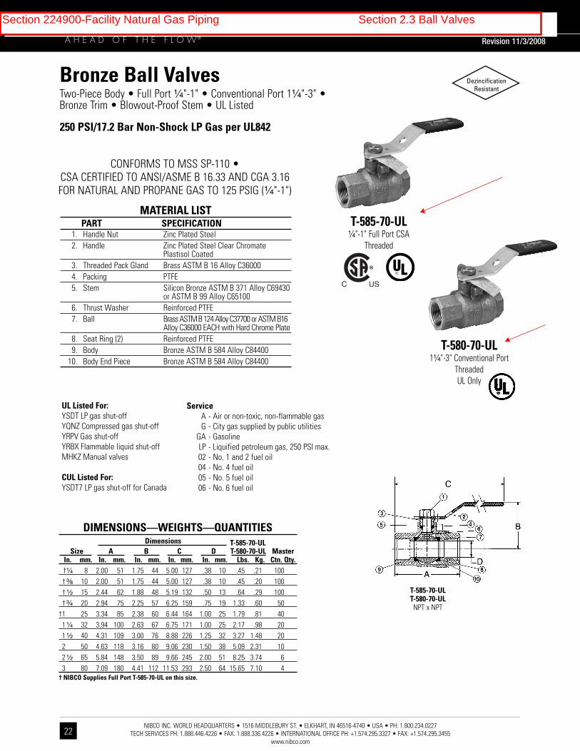
Section 224900-Facility Natural Gas Piping Section 2.4 Pressure Reducing Valves
Section 224900-Facility Natural Gas Piping Section 2.4 Pressure Reducing Valves

Section 224900-Facility Natural Gas Piping Section 2.4 Pressure Reducing Valves

Section 224900-Facility Natural Gas Piping Section 2.4 Pressure Reducing Valves

Section 224900-Facility Natural Gas Piping Section 2.4 Pressure Reducing Valves

9-1
/2"
7-1
/2"
Flo
w D
ire
ctio
n
Arr
ow
Leve
l
Ind
ica
tor
Vis
ua
l
Sta
tus
Win
do
w
Sp
ec
ific
ati
on
s: M
od
el 3
15
F(6
0)
Fla
ng
ed
Va
lve
H
ori
zo
nta
l F
low
7-1
/2"
Ca
lifo
rnia
Se
ism
ic V
alv
es
are
UL
list
ed
in t
he
US
A. C
ert
ifie
d b
y th
e C
alif
orn
ia S
tate
Arc
hit
ect
's
Off
ice
, Ap
pro
ved
by
the
Cit
y o
f Lo
s A
ng
ele
s, a
nd
are
wa
rra
nte
d f
ree
of
ma
nu
fact
ure
r's
de
fect
s fo
r 3
0
yea
rs.
All
valv
es
me
et
Ca
lifo
rnia
Sta
nd
ard
s fo
r E
art
hq
ua
ke
Act
ua
ted
Au
tom
ati
c G
as
Sh
ut
off
Sys
tem
s,
Sta
nd
ard
No
. 12
-23
-1,
AN
SI Z
21
.70
, 19
81
an
d A
SC
E 2
5-9
7 S
tan
da
rds.
Va
lve
Mo
de
l#
31
5F
CA
-DS
A
N
o.
45
R-1
13
R
Len
gth
7-1
/2"
He
igh
t
5-3
/8"
Dia
me
ter
7-1
/2"
No
min
al
Pip
e S
ize
3"
AP
PL
ICA
TIO
N
D
AT
A
60
psi
Dry
Fue
l Gas
Ma
x. P
ress
ure
Fue
l
Re
set
6"
Dia
.
Dia
me
ter
On
Ce
nte
r
6"
Dia
.
3/4
" D
ia.!
(T
yp.)
Dia
me
ter
Ho
le (
Typ
.)
3/4
" D
ia.
Nu
mb
er
of
Ho
les
4
5-3
/8"
Tel
(6
61
) 9
42
-44
99
Fax
(6
61
) 9
42
-09
99
TF
(
80
0)
4-G
AS
-OF
F
ww
w.4
Ga
sO
ff.n
et
23
3 E
ast
Ave
nu
e H
-8 l
La
nca
ste
r, C
A 9
35
35
l
US
A
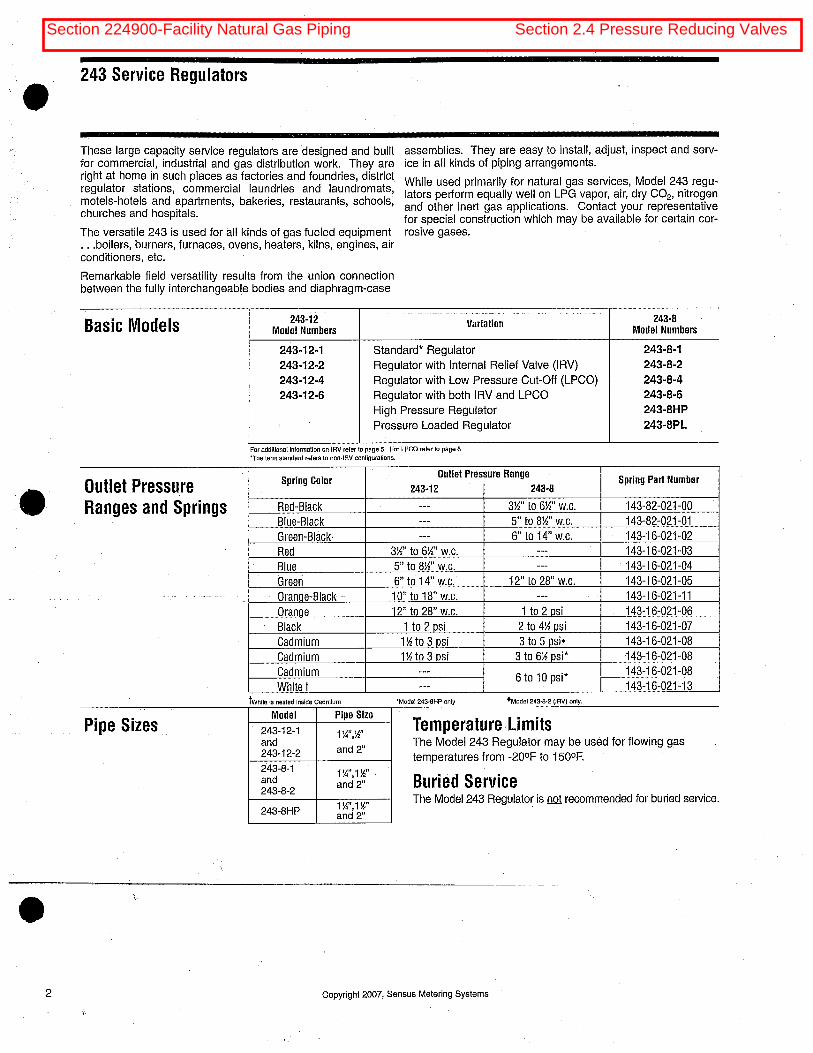
Section 224900-Facility Natural Gas Piping Section 2.5 Earhquake Valve

3”
Mo
de
l 3
15
F C
ali
forn
ia S
eis
mic
Va
lve
Fla
ng
ed
Ho
rizo
nta
l
FL
OW
CA
PA
CIT
YTA
BL
E I
WC
/PS
IG -
Cap
acit
y S
.C.F
.H.
Meri
t R
ati
ng
: C
v 3
36 (
Eq
uiv
ale
nt
Len
gth
of
Pip
e i
s 1
0 F
eet)
Fo
r d
ete
rmin
ing
ap
pro
xim
ate
valu
es a
t sele
cte
d n
atu
ral
gas p
ressu
res t
o 6
0 P
SIG
0.1
0.2
0.3
0.4
0.5
0.6
0.7
0.8
0.9
1.0
2.0
3.0
4.0
5.0
.0036
.0072
.0108
.0144
.0180
.0216
.0252
.0288
.0324
.0360
.0720
.1080
.1440
.1800
5,793
8,192
10,032
11,582
12,948
14,182
15,316
16,372
17,363
18,300
25,849
31,620
36,468
40,724
Pre
ssu
re D
rop
PS
IIW
C8” i
wc I
nle
t
5,834
8,250
10,103
11,665
13,040
14,283
15,426
16,489
17,487
18,431
26,034
31,847
36,731
41,017
14” i
wc I
nle
t
6,292
8,897
10,895
12,579
14,063
15,403
16,636
17,783
18,859
19,877
28,082
34,359
39,633
44,266
3 p
si
Inle
t
6,638
9,386
11,495
13,272
14,837
16,251
17,552
18,762
19,898
20,973
29,633
36,259
41,830
46,725
5 p
si
Inle
t
6,967
9,851
12,064
13,930
15,573
17,057
18,423
19,693
20,886
22,014
31,106
38,066
43,918
49,060
7 p
si
Inle
t
7,433
10,511
12,872
14,862
16,615
18,200
19,657
21,012
22,285
23,489
33,194
40,625
46,875
52,369
10 p
si
Inle
t
8,810
12,459
15,258
17,618
19,696
21,575
23,302
24,910
26,419
27,847
39,361
48,183
55,607
62,139
20 p
si
Inle
t
12,927
18,281
22,390
25,853
28,903
31,661
34,197
36,558
38,774
40,871
57,786
70,756
81,682
91,301
60 p
si
Inle
t
Maxim
um
Pre
ssu
res
of
Avail
ab
leS
izes
7 p
si
60 p
si
Ho
rizo
nta
l V
alv
es
Siz
es A
vail
ab
le
Fla
ng
ed
NP
T
Am
bie
nt
Tem
pera
ture
UL
-40
0to
150
0F
CA
DS
A:
-10
0to
150
0F
Flu
id
Natu
ral
gas
LP
gas
3/4
"1"
11/4
"1
1/2
"2"
21/2
"3"
4"
2"
21/2
"3"
4"
6"
8"
Section 224900-Facility Natural Gas Piping Section 2.5 Earhquake Valve

INSTRUMENT DATA DOCUMENT NO. 100-0107 Rev. 7
SHEET
SAGE PRIME SAGE SIP SPECIFICATIONS
THERMAL MASS FLOW GAS MASS FLOW INTEGRAL STYLE PRIME
METER INSERTION MASS FLOW METER
GENERAL INFORMATION
STYLE: Insertion Mass Flow Meter
SENSOR: Two reference grade platinum RTD clad in 316SS sheath
MATERIAL: Wetted metal components: 316SS
POWER: 24VDC Standard (12VDC or 115/230VAC optional)
POWER DISSIPATION: <2.5 w
ELECTRONICS: Microprocessor based
ELECTRONICS ENCLOSURE: Integral mount, NEMA 4 enclosure
DISPLAY: High contrast photo-emissive OLED graphical display (Flow rate, Totalizer, Temperature)
TURNDOWN: 100 to 1
RESOLUTION: 1000 to 1
LOW END SENSITIVITY: 5 SFPM
FIELD CALIBRATION CHECK: Yes - Digital system allows raw signal validation (milli-watts)
COMMUNICATIONS: Modbus® compliant RS485 RTU communications
APPROVALS: CSA C22.2 (24 VDC); ULI604, Class I, Div 1 & 2, Grps A, B, C, D T4 (24VDC);
CE (AC Power or 24VDC) ATEX: Ex, nA IIC T4X (24VDC model only)
FIELD RECONFIGURABLE: Yes - Sage ADDRESSER or Sage DONGLE
FLOW ACCURACY: +/- 0.5% of Full Scale +/- 1% of reading (Enhanced accuracy optionally available with limited turn-down)
FLOW REPEATABILITY: 0.2%
RESPONSE TIME: 1 second
GAS TEMPERATURE RANGE: -40° TO 200°F STD (if higher temperature needed, contact Sage)
GAS PRESSURE: 500 PSIG (if higher pressure needed, contact Sage)
FLOW OUTPUT: 4 to 20 mA for Rate; 24VDC pulse for Totalized value
TEMPERATURE OUTPUT: Through Modbus® only
AMBIENT TEMPERATURE: -4° F TO 150°F
PROBE STYLE / LENGTH: 1/2" OD Probe (3/4" optional) Lengths 6" to 36"
RELAYS: N/A
FLOW CONDITIONING: Captive Flow Conditioners available upon request with meter purchase
ENCLOSURE DEPTH: DC: 4.35" AC: 5.35"
Make the Wise Choice. Choose Sage Flow Meters.
Sage Metering, Inc / 8 Harris Ct / Building D1 / Monterey, CA 93940 / 866-677-SAGE / 831-242-2030 / Fax 831-655-4965 /
100-0107 SIP Insertion Instrument Data Sheet
www.sagemetering.com
Section 224900-Facility Natural Gas Piping Section 2.6 Gas Meters
• Qty=1, GM-1: 3” line size, Pressure 2 PSI, 5000 MBH• Qty=1, GM-2: 2” line size, Pressure 2 PSI, 2000 MBH• Qty=1, GM-3: 1-1/4” line size, Pressure 2 PSI, 600 MBH
SUBMITTAL DATA Rev. 04/27/05
ASTM A 53 TYPE E GRADE B PIPE
SCOPE
Covers black and hot-dipped galvanized electric-resistance weldedGrade B pipe. Pipe is intended for mechanical and pressureapplications and is acceptable for ordinary uses in steam, water, gasand air lines. Wheatland ASTM A 53 is UL Listed and FM Approved,sizes 1” through 6” nominal, for use in Fire Sprinkler Pipe Applications.Pipe is suitable for welding, threading and grooving. Produced to thelatest revision of ASTM A 53/ 53M, Federal Specification WW-P404 and ASME B36.10M.
MANUFACTURE
The weld seam shall be heat treated after welding to a minimum of1400 0F or be otherwise processed in such a manner that nountempered martensite remains.
HOT-DIPPED GALVANIZED The average weight of zinc coating shall be not less than 1.8 oz. persq. ft. of surface (inside and outside).
When galvanized pipe is bent or otherwise fabricated to a degree whichcauses zinc coating to stretch or compress beyond the limit of elasticity,some flaking of the coating may occur.
HYDROSTATIC AND NONDESTRUCTIVE ELECTRIC TESTING
Hydrostatic inspection test pressures for plain-end pipe are listed inTable X 2.2 of the A53/A 53M specification. Test pressures shall bemaintained for a minimum of five seconds.
Nondestructive electric testing of the weld seam is required on eachlength of ERW pipe NPS 2 and larger.
CHEMICAL REQUIREMENTS
Composition, max. %
Carbon Manganese Phosphorus Sulfur.30 1.20 .05 .045
*Copper *Nickel *Chromium *Molybdenum *Vanadium .40 .40 .40 .15 .08
*The combination of these five elements shall not exceed 1.00%.
TENSILE REQUIREMENTS
Tensile Strength, min.60 000 psiYield Strength, min. 35 000 psiElongation in 2” Refer to A 53 Table x 4.1
BENDING TEST (COLD)
For NPS 2 and underDegree of Bend 900
Diameter of Mandrel 12 x outside pipe diameter
FLATTENING TEST
As a test for ductility of the weld for pipe 2-1/2” NPS and larger, positionthe weld at 00 and alternately at 900 to the direction of force and flattenuntil the OD is 2/3 of the original outside diameter. No cracks shalloccur along the inside or outside surface of the weld.
FREQUENCY OF TESTS
Tensile tests are required on one length of pipe from each lot of 500lengths or fraction thereof for each size. Refer to A 53 specification for frequency of flattening tests.
END FINISH
Plain End: NPS 2 and larger, STD and XS weights: ends beveled toangle of 300, +50, -00 with a root face of 1/16” + 1/32”
Threaded: To ANSI Standard B 1.20.1 Couplings: To ASTM Standard A 865
DIMENSIONS AND WEIGHTS
STANDARD (SCH. 40) BLACK PLAIN END
Nominal ize S
O.D. Inches
Nominal Wall
Weight/ Lb. Ft
2”2-1/2”
3”4”5”6”8”
2.3752.8753.5004.5005.5636.6258.625
.154
.203
.216
.237
.258
.280
.322
3.665.807.58
10.8814.6318.9928.58
EXTRA STRONG (SCH.80) BLACK PLAIN END
Nominal Size
O.D. Inches
Nominal Wall
Weight/ Lb. Ft
2”2-1/2”
3”4”
2.3752.8753.5004.500
.218
.276
.300
.337
5.037.67
10.2615.00
PERMISSIBLE VARIATIONS IN WEIGHT PER FOOT.
Pipe shall not vary more than + 10% from the standard specified.
PRODUCT MARKING
Each length of pipe is continuously stenciled to show the manufacturer,the grade of pipe (ASTM A 53), the kind of pipe E for ElectricResistance Welded, B for Grade B, the size, XS for extra strong, andlength. Stencil markings indicate UL Listing and FM Approval forsizes 1” through 6” nominal for use in Fire Sprinkler PipeApplications. Bar coding is acceptable as a supplementaryidentification method.
PERMISSIBLE VARIATIONS IN WALL THICKNESSMinimum wallthickness at anypoint shall not bemore than 12.5%under nominal wallthickness specified.
PERMISSIBLE VARIATIONS IN OUTSIDE DIAMETER Pipe NPS 2 and larger shall not vary more than + 1% from the standardspecified.
All information contained herein is accurate as known at the time of publication. Wheatland reserves the right to change product specifications without notice and without incurring obligations.
Wheatland Tube | 700 South Dock Street | Sharon, PA 16146 | (800) 257-8182
Section 224900-Facility Natural Gas Piping Section 2.7 Sleeves
GalvanizedStandard Wall

*Dimensional Data for Models C, L, O, S-316. LS-316 and OS-316
RUBBER SEALING ELEMENT PRESSURE PLATE BOLT
ACTUAL FREE AVG. LENGTH(A) (T)THICKNESS LENGTH AFTER ALLEN HEAD (H) THREAD (L)
(B) (C) TIGHTENING HEX ACROSS FLATS SIZE(D)
LS-200-* 0.48” 1.75” 1.38” 1.06” 0.31” 4mm Allen (0.157”) 4.95mm (0.195”) M5-0.8 70mm (2.755”) 0.70 2.25”
LS-275-* 0.61” 1.75” 1.38” 0.97” 0.31” 4mm Allen (0.157”) 4.95mm (0.195”) M5-0.8 70mm (2.755”) 0.75 2.25”
LS-300-* 0.69” 2.37” 1.87” 1.56” 0.44” 6mm Allen (0.236”) 7.87mm (0.310”) M8-1.25 90mm (3.543”) 2.15 3.00”
LS-315-* 0.81” 2.37” 1.87” 1.44” 0.44” 6mm Allen (0.236”) 7.87mm (0.310”) M8-1.25 90mm (3.543”) 2.30 3.00”
LS-325-* 0.88” 2.63” 2.00” 3.13” 1.00” 13mm (0.511”) 5.30mm (0.215”) M8-1.25 90mm (3.543”) 5.50 4.00”
LS-340-* 1.00” 2.70” 2.25” 1.48” 0.66” 13mm (0.511”) 5.30mm (0.215”) M8-1.25 120mm (4.720”) 3.30 4.00”
LS-360-* 1.24” 2.70” 2.25” 2.05” 0.77” 13mm (0.511”) 5.30mm (0.215”) M8-1.25 120mm (4.720”) 5.10 4.00”
LS-400-* 1.38” 3.50” 2.75” 3.50” 1.06” 17mm (0.669”) 6.40mm (0.250”) M10-1.5 130mm (5.118”) 12.00 5.00”
LS-410-* 1.43” 3.37” 2.87” 2.52” 0.88” 17mm (0.669”) 6.40mm (0.250”) M10-1.5 130mm (5.118”) 8.20 5.00”
LS-425-* 1.06” 3.00” 2.25” 3.50” 1.19” 17mm (0.669”) 6.40mm (0.250”) M10-1.5 130mm (5.118”) 10.00 5.00”
LS-475-* 1.56” 3.38” 2.63” 2.63” 0.88” 17mm (0.669”) 6.40mm (0.250”) M10-1.5 130mm (5.118”) 10.00 5.00”
LS-500-* 2.25” 3.75” 2.75” 3.63” 1.06” 19mm (0.748”) 7.50mm (0.300”) M12-1.75 140mm (5.511”) 22.50 5.00”
LS-525-* 2.06” 3.75” 2.87” 3.63” 1.06” 19mm (0.748”) 7.50mm (0.300”) M12-1.75 140mm (5.511”) 21.00 5.00”
LS-575-* 1.81” 3.75” 3.00” 3.00” 1.00” 19mm (0.748”) 7.50mm (0.300”) M12-1.75 140mm (5.511”) 15.50 5.00”
LS-600-* 3.09” 4.00” 3.00” 6.00” 1.90” 30mm (0.748”) 12.50mm (0.490”) M20-2.5 180mm (7.086”) 60.60 6.00”
LS-650-* 2.71” 3.98” 3.00” 3.96” 1.19” 19mm (0.748”) 7.50mm (0.300”) M12-1.75 140mm (5.511”) 26.10 6.00”
Technical Data Submittal SheetSupplement 12/15/10
LINK-SEALMODEL NO.
WEIGHTFOR
10 LINKSECTION
(LBS)
MIN.REQUIREDSEATINGWIDTH
VISIT WWW.LINKSEAL.COM FOR LITERATURE AND INSTALLATION INSTRUCTIONS
For LS-325 through LS-650
For LS-200 through LS-315
Drawings for Reference Only
Section 224900-Facility Natural Gas Piping Section 2.8 Mechanical Sleeves Seals

PSI-Thunderline/Link-Seal®6525 Goforth Street, Houston TX 77021 U.S.A.
Tel: 713-747-6948, Fax: 713-747-6029, Toll Free: 800-423-2410
www.linkseal.com, e-mail: [email protected]
LSTECH-9/27/ 10
©2010, Pipeline Seal & Insulator, Inc
Bolt & Nut SpecificationsStandard: Carbon Steel
Carbon steel, zinc dichromated per ASTM B633, with an
additional corrosion inhibiting proprietary organic coating.
(passes 1470 hour salt spray test)
Tensile Strength = 60,000 psi, minimum.
Option: Stainless Steel
ANSI Type = 316, Per ASTM F593-95
Tensile Strength = 85,000 psi, average.
Link-Seal® Modular Seal Model Properties
Model “C” or “L” Link-Seal Modular Seal
Suitable for use in water, direct ground burial and
atmospheric conditions. Provides electrical isolation
where cathodic protection is required.
Type: Standard
Seal Element: EPDM (Black) or EPDM (Blue)
Pressure Plates: Reinforced Nylon Polymer
Bolts & Nuts: Steel with 2-part Zinc Dichromate &
proprietary corrosion inhibiting coating.
Temp. Range: -40 to +250ºF (-40 to +121ºC)*
Model “S-316” or “LS-316” Link-Seal Modular Seal
For chemical processing & waste water
treatment. EPDM rubber is resistant to most
inorganic acids and alkalis, some organic
chemicals (acetone, alcohol, ketones).
Type: Stainless
Seal Element: EPDM (Black) or EPDM (Blue)
Pressure Plates: Reinforced Nylon Polymer
Bolts & Nuts: 316 Stainless Steel
Temp. Range: -40 to +250ºF (-40 to +121ºC)*
Model “O” Link-Seal Modular Seal
Nitrile rubber is resistant to oils, fuel and many
solvents (gasoline, motor oil, kerosene, methane,
jet fuel, hydraulic fluid, water, etc.).
Type: Oil Resistant
Seal Element: Nitrile (Green) Note: Not U.V resistant.
Pressure Plates: Reinforced Nylon Polymer
Bolts & Nuts: Steel with 2-part Zinc Dichromate &
proprietary corrosion inhibiting coating.
Temp. Range: -40 to +210ºF (-40 to +99ºC)*
Model “OS-316” Link-Seal Modular Seal
Combination of oil resistant rubber and
stainless steel hardware.
Type: Oil Resistant
Seal Element: Nitrile (Green) Note: Not U.V resistant.
Pressure Plates: Reinforced Nylon Polymer
Bolts & Nuts: 316 Stainless Steel
Temp. Range: -40 to +210 ºF (-40 to +99ºC)*
Model “T” Link-Seal Modular Seal
Silicone rubber is ideal for temperature
extremes. The “T” model is one-hour Factory
Mutual approved.
Type: High/Low Temperature
Seal Element: Silicone (Grey)
Pressure Plates: Steel Zinc Dichromate
Bolts: Steel with 2-part Zinc Dichromate &
proprietary corrosion inhibiting coating.
Temp. Range: -67 to +400ºF (-55 to +204ºC)*
Model “FD/FS” Link-Seal Modular Seal
Double seal for added protection.
Type: Fire Seals
Seal Element: Silicone (Grey)
Pressure Plates: Steel zinc dichromate
Bolts: Steel with 2-part Zinc Dichromate
proprietary corrosion inhibiting coating.
Temp. Range: -67 to +400ºF (-55 to +204ºC)*
with EPDM Seal Elements
with Nitrile Seal Elements
with Silicone Seal Elements
Material Properties of Link-Seal Modular Seal ElementsASTM
PROPERTY METHOD EPDM (EPDM L) NITRILE SILICONE
Hardness (shore A) D-2240 50 ±5 (40 ±5) 50 ±5 50 ±5
Tensile D-412 1450 psi 1300 psi 860 psi
Elongation D-412 400% 300% 250%
Compression Set S-395 15% 45% 40%
22 hrs. @ 158ºF (70ºC) 22 hrs. @ 212ºF (100ºC) 22 hrs. @ 350ºF (177ºC)
Specific Gravity D-297 1.10 1.15 1.40
Material Properties of Composite Pressure PlatesASTM
PROPERTY METHOD VALUE
Izod Impact - Notched D-256 2.05 ft-lb/in
Tensile Strength @ Yield D-638 20,000 psi
Tensile Strength - Break D-638 20,250 psi
Flexural Strength @ Yield D-790 30,750 psi
Flexural Modulus D-790 1,124,000 psi
Elongation, Break D-638 11.07%
Specific Gravity D-792 1.38
Moisture Content -- 0.18%
NOTE: Sustains a constant temp. of 325ºF. (163º C.)
* = Sustained operation near temperature limits may
affect life expectancy.
EPDM (Black)EPDM (Blue) Low Durometer
Nitrile (Green)
Silicone (Grey)
* = Sustained operation near temperature limits may
affect life expectancy.
* = Sustained operation near temperature limits may affect life expectancy.
Section 224900-Facility Natural Gas Piping Section 2.8 Mechanical Sleeves Seals

Date______________
Spec. Section______________
HANPLY™ Equipment Plate Specifications
Hanply™ mechanically engraved equipment platesare constructed from a tough multi-layered ABS.
Standard sizes include: 1”x2”, 1”x3”, 1”x4”, 1.5”x4”, 2”x4”, 3”x5” (Other sizes available) Maximum plate size is 24” x 48”. Mounting options: 1/8” holes for screws or self-sticking foam tape adhesive Thicknesses: 1/16” 2ply (Standard), 1/8” in 2ply or 3ply 1/16” and 1/8” Material: Indoor (Matte ABS), Outdoor (Matte Impact Acrylic), or Textured (Co-extruded Impact Acrylic) for extended outdoor durability and abrasion resistance Appearance: Matte finish (Standard) or Textured Finish with beveled edges and square corners Service Temperature: -40°F to 175°F (-40°C to 80°C) Standard colors include: White on Black, White on Blue, White on Red, White on Green, Black on Yellow and Black on White (Other colors available)
www.hansensupply.com | 922 NW Leary Way, Seattle WA 98107 | (800) 782-1235 | [email protected]
Section 224900-Facility Natural Gas Piping Section 2.9 Labeling and identification
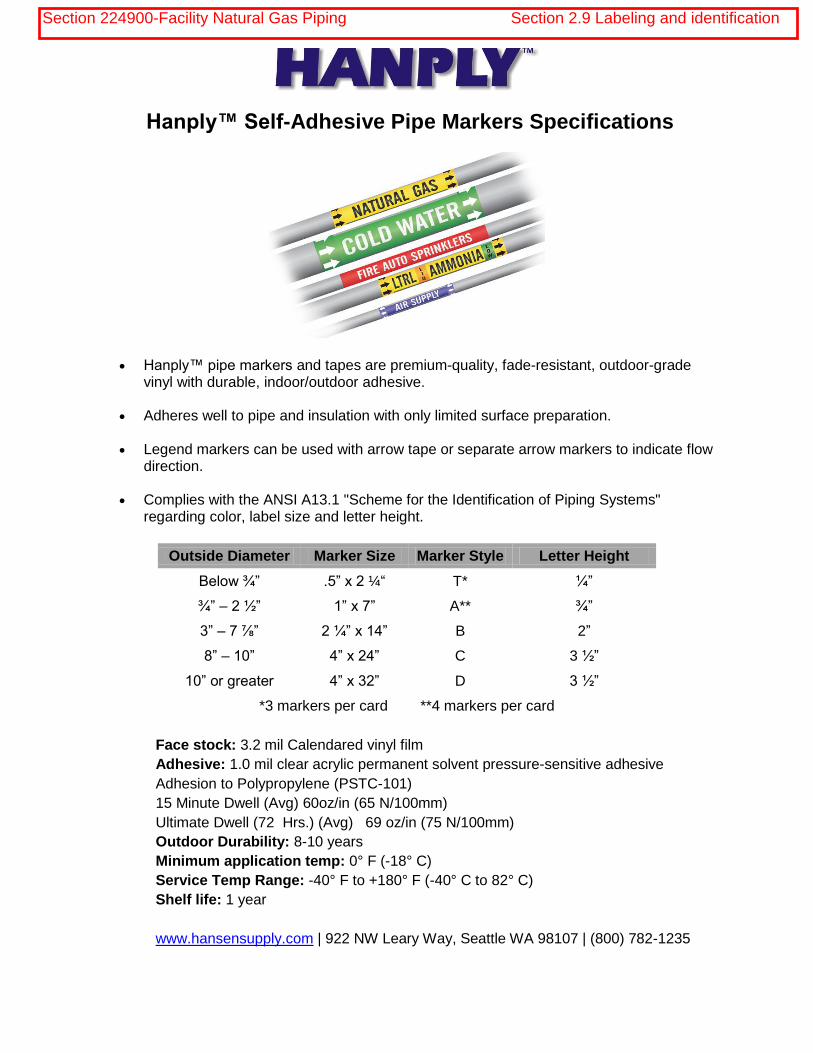
Hanply™ Self-Adhesive Pipe Markers Specifications
Hanply™ pipe markers and tapes are premium-quality, fade-resistant, outdoor-grade vinyl with durable, indoor/outdoor adhesive.
Adheres well to pipe and insulation with only limited surface preparation.
Legend markers can be used with arrow tape or separate arrow markers to indicate flow
direction.
Complies with the ANSI A13.1 "Scheme for the Identification of Piping Systems"
regarding color, label size and letter height.
Outside Diameter Marker Size Marker Style Letter Height
Below ¾” .5” x 2 ¼“ T* ¼”
¾” – 2 ½” 1” x 7” A** ¾”
3” – 7 ⅞” 2 ¼” x 14” B 2”
8” – 10” 4” x 24” C 3 ½”
10” or greater 4” x 32” D 3 ½”
*3 markers per card **4 markers per card
Face stock: 3.2 mil Calendared vinyl film
Adhesive: 1.0 mil clear acrylic permanent solvent pressure-sensitive adhesive
Adhesion to Polypropylene (PSTC-101)
15 Minute Dwell (Avg) 60oz/in (65 N/100mm)
Ultimate Dwell (72 Hrs.) (Avg) 69 oz/in (75 N/100mm)
Outdoor Durability: 8-10 years
Minimum application temp: 0° F (-18° C)
Service Temp Range: -40° F to +180° F (-40° C to 82° C)
Shelf life: 1 year
www.hansensupply.com | 922 NW Leary Way, Seattle WA 98107 | (800) 782-1235
Section 224900-Facility Natural Gas Piping Section 2.9 Labeling and identification

Pipe Markers
HANPLY Pipe Markers
Outside Letter OrderDiameter Height Style Description Style*
8” or greater 31⁄2” Style C: One 4” x 24” marker per card C
21⁄2” to 77⁄8” 13⁄4” Style B: One 2” x 14” marker per card B
3⁄4” to 23⁄8” 3⁄4” Style A: Four 1” x 7” markers per card A
less than 3⁄4” 1⁄2” Style T: Three 2” x 3” markers w/ arrows T
Size Chart
• HANPLY pipe markers are manufactured on fade-resistant, outdoor-grade vinyl with durable, indoor/outdoor adhesive.
• Adheres well to pipe and insulation with only limited surface preparation.• Stock Legends in Blue Meet ASME (ANSI) 2007 standards when used with arrows.• Stock Legends in Black Meet ASME (ANSI) 1996 standards when used with arrows.• Complies with the ANSI A13.1 “Scheme for the Identification of Piping Systems” regarding color, label size and letter height when accompanied with arrows.• Made in the USA• Large inventory means orders ship same day
Don’t see a legend you need? We will gladly match any stock legend from any manufacture. Just let us know the legend and we will add it to your order at stock pricing.
!
?
Icon Glossary S-25 04/11/2006
Customize ItDon’t see a legend in the list? Don’t see a particular size or color you need? We can make it custom. Our custom
markers are sold factory direct! Call, fax or email a list for a quote and delivery estimate.
4
Hanply Pipe Marker Technical Specifications Face stock: 3.2 mil Calendared vinyl filmAdhesive: 1.0 mil clear acrylic permanent solvent pressure-sensitive adhesiveAdhesion to Polypropylene (PSTC-101)15 Minute Dwell (Avg) 60oz/in (65 N/100mm)Ultimate Dwell (72 Hrs.) (Avg) 69 oz/in (75 N/100mm)Outdoor Durability: 8-10 yearsMinimum application temp: 0° F (-18° C)Service Temp Range: -40° F to +180° F (-40° C to 82° C)Shelf life: 1 year
!
?
Icon Glossary S-25 04/11/2006
Print on demandMake your own Pipe Markers onsite and on time with our 10 year outdoor label printers. Portable and benchtop units available. See
Pages 18-19 for more info.
800.782.1235
Section 224900-Facility Natural Gas Piping Section 2.9 Labeling and identification

5
HANPLY Pipe Markers
Pipe
Mar
kers
Background Catalog Legend Color No.
Background Catalog Legend Color No.
Background Catalog Legend Color No.
*Legends listed in Blue meet ANSI 2007 Standards
ARROWS ---> Blue PS098 –*ARROWS ---> Brown PS093 –*ARROWS ---> Green PS096 –*ARROWS ---> Orange PS095 –*ARROWS ---> Red PS097 –*ARROWS ---> White PS094 –*ARROWS ---> Yellow PS099 –*ACID Yellow PS231 –*ACID Orange PS268 –*ACID VENT Yellow PS232 –*ACID VENT Orange PS269 –*ACID WASTE Yellow PS233 –*ACID WASTE Orange PS270 –*AIR Yellow PS101 –*AIR Blue PS102 –*AIR Green PS103 –*AIR RETURN Blue PS234 –*AIR SUPPLY Blue PS104 –*ALCOHOL Yellow PS237 –*AMMONIA Yellow PS105 –*AMMONIA Orange PS271 –*ARGON Green PS106 –*ARGON Orange PS272 –*ASBESTOS FREE Blue PS107 –*ASBESTOS FREE INSULATION Blue PS108 –*BOILER FEED Green PS242 –*CARBON DIOXIDE Yellow PS202 –*CARBON DIOXIDE Orange PS274 –*CHEMICAL FEED Yellow PS247 –*CHILLED WATER Green PS111 –*CHILLED WATER RETURN Green PS112 –*CHILLED WATER SUPPLY Green PS113 –*CHLORINE Yellow PS249 –*CHLORINE Orange PS275 –*CITY WATER Green PS114 –*COLD WATER Green PS115 –*COMPRESSED AIR Yellow PS116 –*COMPRESSED AIR Green PS117 –*COMPRESSED AIR Blue PS118 –*CONDENSATE Yellow PS119 –*CONDENSATE Green PS276 –*CONDENSATE DRAIN Yellow PS120 –*CONDENSATE DRAIN Green PS121 –*CONDENSATE PUMP DISCH. Yellow PS260 –*CONDENSATE RETURN Yellow PS122 –*CONDENSATE RETURN Green PS277 –*CONDENSATE SUPPLY Yellow PS263 –*CONDENSATE SUPPLY Green PS278 –*CONDENSER WATER Green PS123 –*CONDENSER WATER RETURN Green PS124 –*CONDENSER WATER SUPPLY Green PS125 –*COOLING WATER Green PS126 –* COOLING WATER RETURN Green PS127 –*COOLING WATER SUPPLY Green PS227 –*CRUDE OIL Yellow PS264 –*DEIONIZED WATER Green PS128 –*DEIONIZED WATER RETURN Green PS201 –*DEIONIZED WATER SUPPLY Green PS206 –*DIGESTED SLUDGE Yellow PS265 –*DISCHARGE Yellow PS267 –*DOMESTIC COLD WATER Green PS129 –*DOM. COLD WATER SUPPLY Green PS130 –*DOM. COLD WATER RETURN Green PS279 –*DOMESTIC HOT WATER Yellow PS131 –*DOMESTIC HOT WATER Green PS280 –*DOM. HOT WATER RETURN Yellow PS132 –*DOM. HOT WATER RETURN Green PS281 –*DOM. HOT WATER SUPPLY Yellow PS133 –*DOM. HOT WATER SUPPLY Green PS282 –*
DRAIN Green PS134 –*DRAIN Yellow PS253 –*EXHAUST Yellow PS213 –*EXHAUST Blue PS283 –*EXHAUST AIR Blue PS222 –*FILTERED WATER Green PS225 –*FIRE AUTO SPRINKLERS Red PS135 –*FIRE PROTECTION WATER Red PS136 –*FUEL OIL Yellow PS137 –*FUEL OIL RETURN Yellow PS224 –*FUEL OIL SUPPLY Yellow PS207 –*FUEL OIL VENT Yellow PS208 –*GAS Yellow PS138 –*GLYCOL Yellow PS139 –*GLYCOL Orange PS284 –*GLYCOL RETURN Yellow PS140 –*GLYCOL RETURN Orange PS285 –*GLYCOL SUPPLY Yellow PS141 –*GLYCOL SUPPLY Orange PS286 –*HEATING RETURN Yellow PS142 –*HEATING RETURN Green PS287 –*HEATING SUPPLY Yellow PS143 –*HEATING SUPPLY Green PS288 –*HEATING WATER Yellow PS144 –*HEATING WATER Green PS289 –*HEATING WATER RETURN Yellow PS145 –*HEATING WATER RETURN Green PS290 –*HEATING WATER SUPPLY Yellow PS146 –*HEATING WATER SUPPLY Green PS291 –*HIGH PRESSURE AIR Yellow PS292 –*HIGH PRESSURE AIR Blue PS293 –*HIGH PRESS. CONDENSATE Yellow PS336 –* HIGH PRESS. CONDENSATE Green PS294 –*HIGH PRESSURE GAS Yellow PS295 –*HIGH PRESS. STEAM Yellow PS216 –*HIGH PRESS. STEAM Green PS296 –*HOT WATER Yellow PS147 –*HOT WATER Green PS297 –*HOT WATER RECIRCULATION Yellow PS148 –*HOT WATER RECIRCULATION Green PS298 –*HOT WATER RETURN Yellow PS149 –*HOT WATER RETURN Green PS299 –*HOT WATER SUPPLY Yellow PS150 –*HOT WATER SUPPLY Green PS300 –*INDUSTRIAL HOT WATER Yellow PS203 –*INDUSTRIAL HOT WATER Green PS301 –*INDUSTRIAL WATER Green PS151 –* INSTRUMENT AIR Blue PS302 –*LAB VACUUM Yellow PS209 –*LAB VACUUM Green PS303 –*LAB VENT Yellow PS199 –*LAB VENT Green PS304 –*LAB WASTE Yellow PS198 –*LAB WASTE Green PS305 –*LOW PRESSURE AIR Blue PS306 –*LOW PRESS. CONDENSATE Yellow PS152 – *LOW PRESS. CONDENSATE Green PS307 –*LOW PRESSURE GAS Yellow PS308 –*LOW PRESS. NATURAL GAS Yellow PS309 –*LOW PRESSURE STEAM Yellow PS153 – *LOW PRESSURE STEAM Green PS310 –*MAKE-UP WATER Green PS210 –*MEDICAL AIR Yellow PS154– * MEDICAL AIR Blue PS311 –*MEDICAL VACUUM White PS155– * MEDICAL VACUUM Green PS312 –*MEDIUM PRESS. CONDENSATE Yellow PS218 –*MEDIUM PRESS. CONDENSATE Green PS313 –*MEDIUM PRESS. GAS Yellow PS219 –*
MEDIUM PRESS. NATURAL GAS Yellow PS156 – *MEDIUM PRESS. STEAM Yellow PS314 –*MEDIUM PRESS. STEAM Green PS315 –*NATURAL GAS Yellow PS157 – *NITROGEN Green PS158 – *NITROGEN Blue PS159 – *NITROGEN Black PS371 – *NITROGEN Orange PS316 –*NON-POTABLE WATER Yellow PS160 – *NON-POTABLE WATER Green PS317 –*OIL Yellow PS318 –*OVERFLOW Yellow PS161 – *OVERFLOW Green PS319 –*OXYGEN Green PS162 – * OXYGEN Yellow PS163 – *PLANT AIR Yellow PS164 – *PLANT AIR Blue PS320 –*PLUMBING VENT Green PS321 –*POTABLE WATER Yellow PS165 – *POTABLE WATER Green PS322 –*PROCESS WATER Green PS166 – *PROPANE GAS Yellow PS167 – *PUMPED CONDENSATE Yellow PS323 –*PUMPED CONDENSATE Green PS324 –*RAIN WATER Green PS168 – *REFRIGERANT LIQUID Yellow PS169 – *REFRIGERANT LIQUID Green PS325 –*REFRIGERANT SUCTION Yellow PS205 –*REFRIGERANT SUCTION Green PS326 –*RETURN Green PS170 – *RETURN Yellow PS171 – *ROOF DRAIN Green PS172 – *SANITARY DRAIN Green PS327 –*SANITARY SEWER Green PS173 – *SANITARY SEWER Yellow PS174 – *SANITARY VENT Yellow PS175 – *SANITARY VENT Green PS328 –*SANITARY WASTE Yellow PS176 – *SANITARY WASTE Green PS329 –*SPRINKLER Red PS177 – *SPRINKLER FIRE Red PS178 – *SPRINKLER WATER Red PS179 – *STEAM Yellow PS180 – *STEAM Green PS330 –*STEAM RETURN Yellow PS262 –*STEAM RETURN Green PS331 –*STEAM SUPPLY Yellow PS211 –*STEAM SUPPLY Green PS332 –*STORM DRAIN Green PS181 – *STORM SEWER Green PS182 – *STORM WATER Green PS250 –*SUPPLY Green PS183 – *SUPPLY Yellow PS184 – *TEMPERED WATER Yellow PS185 – *TEMPERED WATER Green PS334 –*TOWER WATER Green PS186 – *TREATED WATER Green PS335 –*VACUUM Yellow PS187 – *VACUUM Green PS188 – *VENT Yellow PS189 – *VENT Green PS190 – *WASTE Yellow PS191 – *WASTE Green PS192 – *WASTE WATER Green PS251 –*WATER Yellow PS193 – *WATER Green PS194 – *
www.hansensupply.com
Section 224900-Facility Natural Gas Piping Section 2.9 Labeling and identification
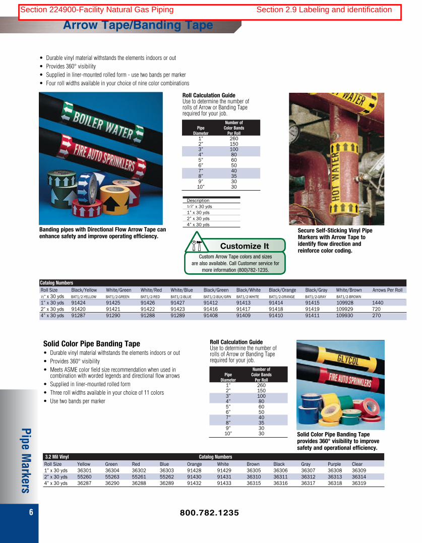
6
Pipe Markers
Arrow Tape/Banding Tape
• Durable vinyl material withstands the elements indoors or out• Provides 360° visibility• Supplied in liner-mounted rolled form - use two bands per marker• Four roll widths available in your choice of nine color combinations
Banding pipes with Directional Flow Arrow Tape can enhance safety and improve operating efficiency.
Roll Calculation Guide Use to determine the number of rolls of Arrow or Banding Tape required for your job. Number of Pipe Color Bands Diameter Per Roll 1” 260 2” 150 3” 100 4” 80 5” 60 6” 50 7” 40 8” 35 9” 30 10” 30
Secure Self-Sticking Vinyl Pipe Markers with Arrow Tape to identify flow direction and reinforce color coding.
!
?
Icon Glossary S-25 04/11/2006
Customize It
Description 1/2” x 30 yds 1” x 30 yds 2” x 30 yds 4” x 30 yds
Custom Arrow Tape colors and sizes are also available. Call Customer service for
more information (800)782-1235.
Solid Color Pipe Banding Tape• Durable vinyl material withstands the elements indoors or out• Provides 360° visibility• Meets ASME color field size recommendation when used in combination with worded legends and directional flow arrows• Supplied in liner-mounted rolled form• Three roll widths available in your choice of 11 colors• Use two bands per marker
Roll Calculation Guide Use to determine the number of rolls of Arrow or Banding Tape required for your job. Number of Pipe Color Bands Diameter Per Roll 1” 260 2” 150 3” 100 4” 80 5” 60 6” 50 7” 40 8” 35 9” 30 10” 30 Solid Color Pipe Banding Tape
provides 360° visibility to improve safety and operational efficiency.
3.2 Mil Vinyl Catalog NumbersRoll Size Yellow Green Red Blue Orange White Brown Black Gray Purple Clear1” x 30 yds 36301 36304 36302 36303 91428 91429 36305 36306 36307 36308 363092” x 30 yds 55260 55263 55261 55262 91430 91431 36310 36311 36312 36313 363144” x 30 yds 36287 36290 36288 36289 91432 91433 36315 36316 36317 36318 36319
Roll Size Black/Yellow White/Green White/Red White/Blue Black/Green Black/White Black/Orange Black/Gray White/Brown Arrows Per Roll1⁄2” x 30 yds BAT1/2-YELLOW BAT1/2-GREEN BAT1/2-RED BAT1/2-BLUE BAT1/2-BLK/GRN BAT1/2-WHITE BAT1/2-ORANGE BAT1/2-GRAY BAT1/2-BROWN1” x 30 yds 91424 91425 91426 91427 91412 91413 91414 91415 109928 14402” x 30 yds 91420 91421 91422 91423 91416 91417 91418 91419 109929 7204” x 30 yds 91287 91290 91288 91289 91408 91409 91410 91411 109930 270
Catalog Numbers
800.782.1235
Section 224900-Facility Natural Gas Piping Section 2.9 Labeling and identification

Hanply™ Brass Valve Tag Specifications
Hanply™ engraved brass valve tags constructed from 18 gauge brass.
Standard sizes include: 1.5” Round, 2” Round, 1”x3” (Other sizes available) Mounting options: 3/16” holes for chain Thicknesses: 18 gauge Material: Solid Brass Service Temperature: up to 1200°F (233°F ink filled) Average Outdoor Durability: 5-7 years Standard Fill Colors include: Black, Red and White Enamel
www.hansensupply.com | 922 NW Leary Way, Seattle WA 98107 | (800) 782-1235
Section 224900-Facility Natural Gas Piping Section 2.9 Labeling and identification