Sub-microamp Microcontroller and Wireless Transceivers ... · 03/2014 M. Buccini Sub-microamp...
23
03/2014 M. Buccini Sub-microamp Microcontroller and Wireless Transceivers, Protocols, Network Architectures Mark E. Buccini March 2014
Transcript of Sub-microamp Microcontroller and Wireless Transceivers ... · 03/2014 M. Buccini Sub-microamp...

03/2014 M. Buccini
Sub-microamp Microcontroller and Wireless
Transceivers, Protocols, Network Architectures
Mark E. Buccini March 2014
Presenter
Presentation Notes
The content of this paper focuses on real-work techniques useable right now that enable sub-microamp small computing systems appropriate for energy harvesting. The three areas to be discussed include, hardware management, sensor processing, and efficient data processing

Mark E. Buccini
03/2014 M. Buccini
• Mark is responsible for product and marketing strategy as a staff member at Texas Instruments with 25 years experience.
• He has recently driven the introduction of magnetic hall-effect sensors, monolithic automotive MCU-based integrated BLDC motor drivers and creation of the Smart Grid Business Unit.
• He was directly responsibly for the world-wide launch and new product definition of the MSP430 family of ultra-low power microcontrollers.
• Mark has a Bachelors of Science degree in Electrical Engineering from Oakland University in Rochester Michigan.

Agenda
03/2014 M. Buccini
• Standby as the normal mode • Managing overall system power budget • Supply voltage • Power gating sensor • Sensor measurement • Importance of energy aware firmware • EH /WSN Demonstration

ULP Embedded Systems Basics
P = Pdyn + Pstat = CV2f + VIleak
03/2014 M. Buccini
• Both frequency and voltage can be controlled • Lowering frequency has a linear effect • Lowering voltage has a squared the effect
Presenter
Presentation Notes
Both frequency and voltage can be controlled in an embedded system. Voltage has the biggest impact in reducing power consumption because contribution is squared. To reduce overall power, both voltage and power should be reduced to a minimum. Static current is a fixed source and can be treated as a constant. Power managing internal and external peripherals is required for ULP operation. Effective code is an absolute must.
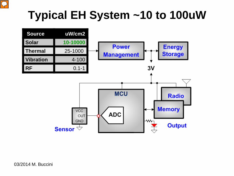
Typical EH System ~10 to 100uW
03/2014 M. Buccini
Source uW/cm2 Solar 10-10000 Thermal 25-1000 Vibration 4-100 RF 0.1-1
Presenter
Presentation Notes
Energy in at 3V - Harvester, Management and Storage Signal Chain – Sensor, conversion processing Output

ULP/EH/WSN Typical Activity Profile
03/2014 M. Buccini
• Sleep mode as normal mode • Average power approaches sleep • Peaks must not be “extreme”

• MSP430F20xx Tiny workhouse since 2005 • 0.35um single-supply domain, nothing special
0.5uA Standby Mode MCU
03/2014 M. Buccini

MCU Clocking and Voltage Impact
TEMP VCC TYP UNIT
Active 1MHz Flash
N//A 2.2V 220 uA
N/A 3V 300
Standby 12kHz VLO
25°C 2.2V
0.5
uA 85°C 1.0
25°C 3V
0.6
85°C 1.3
VLO/8 22°C 2.0V 0.3uA uA
MSP430F20x from datasheet
1-16MHzDCO
Peripherals
Peripherals
CPU32kHz… /8
… /8
… /8
12kHzVL0
Fault
from bench test • Active 25% reduction 3V to 2.2V • Standby is the normal mode • Current is for entire chip … clock, memory, BOR …
03/2014 M. Buccini
Presenter
Presentation Notes
Reduced standby power consumption - also know as real-time clock (RTC) or LPM3 mode current has been reduced to less than 1 micro amp at 3V. This power consumption can be achieved using an external 32kHz crystal or the VLO. Reducing voltage and reducing frequency have an impact on standby current.

Linear Hall Sensor – VCC, GND and OUT
03/2014 M. Buccini
Sensor

Power Gate External Sensors
• Power gate sensor to eliminate static Leak • MeasureSensor();
– 50us – @3mA
• @1Hz Sample – 0.000050*3mA – 0.150uA adder on average
• @3Hz Sample – 0.450uA adder
03/2014 M. Buccini
Presenter
Presentation Notes
External device should always only be enabled when needed.

ADC Sensor Sampling
• ADC10 = 600uA @200kSPS Reference = 250uA
• @1Hz Sample – 0.004uA = 850uA/200,000
• @3Hz Sample – 0.012uA adder
03/2014 M. Buccini
Presenter
Presentation Notes
While the datasheet specifies the 10-bit ADC at 600uA, this is maximum conversion speed of 200ksps. Taking a single conversion once per-second reduces the power contribution of the ADC to the overall system to virtually nothing. The ADC conversion rate is completely configurable.

Energy Aware Firmware
MCU GPIO
0.01% Load #pragma vector=WDT_VECTOR _interrupt watchdog_timer (void){ P1OUT ^= 0x01; // Toggle }
// Setup timer output unit CCTL1 = OUTMOD0_1; _BIS_SR(CPUOFF);
0% CPU Load!
while (1){ P1OUT ^= 0x01; // Toggle __delay_cycles(10000); // Delay }
100% CPU Load
03/2014 M. Buccini
Presenter
Presentation Notes
The example shows an effective use of peripherals for a 20Hz square ware generation. With a pure software function to drive an output in the example, the CPU is 100% active, using the maximum power. This is true regardless of the architecture, the CPU is consumed 100%. Using a peripheral to drive a function allows the CPU to be turned off, saving power or allowing the CPU to work on other activities. In general it is recommended to move basic bit manipulation and data movement as far as possible to the peripherals.

For Demonstration
• $20 eZ430-F2013 Development tool • LED already on target used as indicator • Magnet Hall Sensor 3-pin added • MCU GPIO used to create Sensor VCC and GND for • MSP430F2013 replaced with MSP430F2012
LED VCC MSP430F2012
GND
03/2014 M. Buccini
Hall Sensor
Presenter
Presentation Notes
Because the eZ430 target board can be disconnected from the emulation interface, the complete tool is much more than a demo or evaluation system. An entire MSP430F20xx project can be implemented using just the eZ430. Competing basic demo or evaluation systems contain the emulation and target device on a single board preventing a stand alone project implementation. The emulation interface can not be separated from the target device. Only simple demonstrations or limited evaluation are possible. For this project the ez430 is slightly modified replacing the ‘F2013 (16-bit ADC) with the ‘F2012 (10-bit ADC) and an 3-pin Linear Hall Sensor added across P1.1-P1.2-P1.3.

>1mA NOT ULP Sensor Sampling Code P1OUT = HALLPWR; // PWR to HALL while (1) { ADC10CTL0 |= ADC10SC; // Sampling start while (ADC10CTL1 & ADC10BUSY); // ADC10BUSY? if ((ADC10MEM < 0x182) || (ADC10MEM > 0x1C2)) P1OUT |= LED; // LED on else P1OUT &= ~LED; // LED off ADC10MEM_prev = ADC10MEM; }
• Sensor permanently powered • CPU operates full speed in an endless loop • ADC and Reference operate full speed permanently
03/2014 M. Buccini
Presenter
Presentation Notes
This example does not use ULP techniques and is not recommended

1uA ULP Sensor Sampling Code while (1){ _BIS_SR(LPM3_bits + GIE); // *NORMAL MODE* P1OUT |= HALLPWR; // *PWR Sensor ADC10CTL0 = SREF_1 + ADC10SHT_2 + REF2_5V + REFON + ADC10ON; __delay_cycles(50); // *50us REF and HALL POR* ADC10CTL0 |= ADC10SC; // Sampling start while (ADC10CTL1 & ADC10BUSY); // ADC10BUSY? P1OUT &= ~HALLPWR; // *noPWR to Sensor* if ((ADC10MEM < 0x182) || (ADC10MEM > 0x1C2)) // 0.9V><1.1V P1OUT |= LED; // LED on else P1OUT &= ~LED; // LED off } __interrupt void watchdog_timer (void){ _BIC_SR_IRQ(LPM3_bits); // Exit LPM3 }
03/2014 M. Buccini
Presenter
Presentation Notes
This example uses ULP techniques and is recommended. Application operates typically in standby with the CPU and ADC off, sensor un-powered. A timer driven interrupt returns the application to active where the CPU uses a GPIO to power the sensor, enable the ADC and reference, wait 50us for the sensor and reference to settle an initiates and ADC sample. The data is and processes comparing if the sensor output is below 0.9V or greater than 1.1V indicating the presence of a magnetic field – the sensor quiescent output is 1V with no magnetic field. The active time of the application is in a a very narrow window of approximately 100 us total. In this example the average current just over 1uA.

Starting Point … Flashing the LED
16-bitADC
• Often a marketing must-have for electronic system-functioning-properly indicator
• ~5mA pulse for 1ms • 1/second
– 0.1% duty cycle – 5uA adder on average
• 1/5 second – 0.02% duty cycle – 1uA adder
03/2014 M. Buccini
Presenter
Presentation Notes
Simply flashing an LED can have a major impact on total system power.

WSN Consideration for EH
• Ultra-low power consumption – Peak – Average – Idle – Start-up
• High packet efficiency • Robust and immune to interference • Security • Multi-vendor interoperability
03/2014 M. Buccini

03/2014 M. Buccini
Add WSN Simplicity/e430-RF2500
TX packet
2.49ms
1uA
20mA
PLL Cal
Charge ~ 28uAs
• 28uA @ 1Hz TX packet interval on average • 5.6uA @ 0.2Hz
Presenter
Presentation Notes
SLAA378D Ez430-rf2500 running simplicity 29uAs, 89uWs for TX function 35uA/s divided /5 ~ 7uA with sensor processing + 1.3uA standby ~ 8.5uA RX may be longer if free channels is not found

Add BLE WSN CC2541
03/2014 M. Buccini
2.7ms
1uA
20mA
• 24uA @ 1Hz TX packet interval on average • 5uA @ 0.2Hz
Charge ~ 24uAs
Presenter
Presentation Notes
AN092 17mA peak, 24uA average 30.8uAs, 92uWs @ 3V

WSN Packet Efficiency
03/2014 M. Buccini
BLE Payload/Total length = 31/47 = 0.66 > 66% efficient

Extra: WSN Choices
03/2014 M. Buccini
Dongle,computer and special GUI
•BLE is standard on Smart Phones and very low power •ISM special hand-crafted RF and BLE offer comparable power … but consider cost of special R&D and support … worth it?
•Any WSN should be low power, robust and noise immune

1uA Sensor Sampling Solution
03/2014 M. Buccini
// MSP430F2012 + DRV5050 // ----------------------- // Standby LPM3 = 0.500uA // Sensor@3Hz = 0.450uA // ADC10 @3Hz = 0.012uA // Main() = 0.100uA // ----------------------- // Total @3Hz ~ 1.100uA @1Hz ~0.800uA // WSN @0.2Hz ~ 5.000uA // With LED 6.100uA
• MCU, ADC and Sensors can be managed • WSN is the bottleneck

Thank You
03/2014 M. Buccini