STUDY OF RIDE COMPARISON BETWEEN FIXED CABIN AND …
9
STUDY OF RIDE COMPARISON BETWEEN FIXED CABIN AND SUSPENDED CABIN FOR COMMERCIAL VEHICLE M.Sachidhanandam*, R. Saravanakumar, S. Rajendra Kumar Department of Mechanical Engineering, SRM University, Tamilnadu, India. *Corresponding author: [email protected] ABSTRACT: Vibrations due to the irregularities of the road and general vehicle handling results in fatigue of truck drivers. These vibrations are undesired and results in faster fatigue and fitness issues to the driver and co- passenger. Light duty and medium duty trucks are not equipped with fixed cab mounting to chassis frame using rubber mounts. Such fixations result in the transmission of vibrations directly to the driver. These vibrations can be filtered out and minimized by using dampers in cab mounts. This project deals with the introduction of cab suspension for a medium duty truck with minimal changes to the surrounding parts, and analysis of results. Cab damper is added to the existing fixed cabin mounting by Computer Aided Design (CAD) software the improvements are analysed by Multi body dynamics, to understand the benefits. ISO Standards for human vibration measurement are used for reference. Inference from the analysis shows that acceleration is reduced by with the usage of dampers in cabin mount as the energy is observed by the damper which filters out unnecessary vibrations to driver. I. INTRODUCTION 1.0 Overview Drivers of the truck drivers spend most of the time inside the truck cabins. Vibrations are induced because of the irregularities observed in the road, steering and general handling on the cabin and consequently resulting to the driver as shown in figure 1.Such kind of forces results in undesired vibrations and results in faster fatigue of drivers and reduced efficiency and reduced productivity. Cab suspensions are offered for better ride comfort; however they are used only on high end trucks as they are costly and not low end trucks. Cab suspension is the system which is placed between the chassis and cabin using dampers and appropriate systems. Loads transmitted from the chassis frame are taken by the suspension. The primary function of cab suspension systems is to reduce the vibrations transferred to the truck driver. Study made for the introduction of cab suspension in low end trucks and to analyse the benefits.Irregularities in the road induces vibration to the truck. The primary or basis suspension of the truck would dampen most of the vibrations. They basically operate within the range of 1 and 2 Hz of natural frequencies. The filtered out vibrations still pass on to the cabin and the basic principle is cab suspension should operate with the natural frequency of with sufficiently larger than the primary suspension. Else this would result in the resonance and increase or adding up of amplitude of vibrations, resulting in compounding of issue.Hence design of cab suspension is critical for the safety and ride comfort of the truck, as uncomfortable ride result in tiredness and results in safety issues as shown in below figure1. ISSN NO: 0776-3808 http://aegaeum.com/ Page No: 109 AEGAEUM JOURNAL Volume 11, Issue 1, 2020
Transcript of STUDY OF RIDE COMPARISON BETWEEN FIXED CABIN AND …

STUDY OF RIDE COMPARISON BETWEEN FIXED CABIN AND SUSPENDED CABIN FOR COMMERCIAL VEHICLE
M.Sachidhanandam*, R. Saravanakumar, S. Rajendra Kumar
Department of Mechanical Engineering, SRM University, Tamilnadu, India. *Corresponding author: [email protected]
ABSTRACT: Vibrations due to the irregularities of the road and general vehicle handling results in fatigue of truck drivers. These vibrations are undesired and results in faster fatigue and fitness issues to the driver and co-passenger. Light duty and medium duty trucks are not equipped with fixed cab mounting to chassis frame using rubber mounts. Such fixations result in the transmission of vibrations directly to the driver. These vibrations can be filtered out and minimized by using dampers in cab mounts. This project deals with the introduction of cab suspension for a medium duty truck with minimal changes to the surrounding parts, and analysis of results. Cab damper is added to the existing fixed cabin mounting by Computer Aided Design (CAD) software the improvements are analysed by Multi body dynamics, to understand the benefits. ISO Standards for human vibration measurement are used for reference. Inference from the analysis shows that acceleration is reduced by with the usage of dampers in cabin mount as the energy is observed by the damper which filters out unnecessary vibrations to driver.
I. INTRODUCTION
1.0 Overview Drivers of the truck drivers spend most of the time inside the truck cabins. Vibrations are induced because
of the irregularities observed in the road, steering and general handling on the cabin and consequently
resulting to the driver as shown in figure 1.Such kind of forces results in undesired vibrations and results
in faster fatigue of drivers and reduced efficiency and reduced productivity. Cab suspensions are offered
for better ride comfort; however they are used only on high end trucks as they are costly and not low end
trucks. Cab suspension is the system which is placed between the chassis and cabin using dampers and
appropriate systems. Loads transmitted from the chassis frame are taken by the suspension.
The primary function of cab suspension systems is to reduce the vibrations transferred to the truck driver.
Study made for the introduction of cab suspension in low end trucks and to analyse the
benefits.Irregularities in the road induces vibration to the truck. The primary or basis suspension of the
truck would dampen most of the vibrations. They basically operate within the range of 1 and 2 Hz of
natural frequencies. The filtered out vibrations still pass on to the cabin and the basic principle is cab
suspension should operate with the natural frequency of with sufficiently larger than the primary
suspension. Else this would result in the resonance and increase or adding up of amplitude of vibrations,
resulting in compounding of issue.Hence design of cab suspension is critical for the safety and ride
comfort of the truck, as uncomfortable ride result in tiredness and results in safety issues as shown in
below figure1.
ISSN NO: 0776-3808
http://aegaeum.com/ Page No: 109
AEGAEUM JOURNAL
Volume 11, Issue 1, 2020

Figure 1 – Schematic illustration of vibration exposure influencing human body
II. Problem statement
Exposure to whole body vibration results in maximum during the seated postures which is normal during
the vehicle operation. Also, the entire vibration is normally transmitted based on the contact with
vibrating media. This is probably the driver seat back-rest or the floor inside cabin.Hence the natural
frequency of cab suspension is designed such a way that it operates between 2 and 3 Hz. There are lot of
cabin suspensions available and are used based on the application. It is to be noted that human body is
very much sensitive upto the vibration of 15 Hz and needs to be addressed critically in this range.
Figure 2 – Schematic illustration of vibration types on a seated human posture
Usually, if the human body is exposed to whole body vibration, then it is results in fatigue, tiredness and
discomfort to the driver. It is also proved that experiencing the continuous vibration is a prominent fitness
hazard factor for low back hurting. Also, it is widely acknowledged that exposure to high levels of whole-
body vibration happens in trucks. Hence, it is important to validate the fitness consequence from exposure
time and vibration levels during vehicle operation. The widespread standards established are ISO 2631-1
(1997) and ISO2631-5 (2004).Continuous interaction to whole-body vibration leads in continuous
physical damage or disrupting the human nervous system. Continuous contact to whole-body vibration
results to chronical physical impairments and interrupts the lower spinal region of human.
ISSN NO: 0776-3808
http://aegaeum.com/ Page No: 110
AEGAEUM JOURNAL
Volume 11, Issue 1, 2020
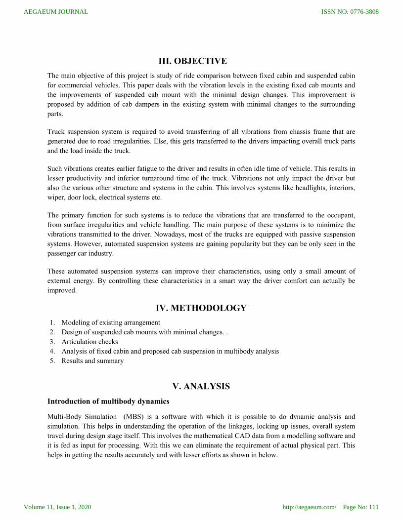
III. OBJECTIVE
The main objective of this project is study of ride comparison between fixed cabin and suspended cabin
for commercial vehicles. This paper deals with the vibration levels in the existing fixed cab mounts and
the improvements of suspended cab mount with the minimal design changes. This improvement is
proposed by addition of cab dampers in the existing system with minimal changes to the surrounding
parts.
Truck suspension system is required to avoid transferring of all vibrations from chassis frame that are
generated due to road irregularities. Else, this gets transferred to the drivers impacting overall truck parts
and the load inside the truck.
Such vibrations creates earlier fatigue to the driver and results in often idle time of vehicle. This results in
lesser productivity and inferior turnaround time of the truck. Vibrations not only impact the driver but
also the various other structure and systems in the cabin. This involves systems like headlights, interiors,
wiper, door lock, electrical systems etc.
The primary function for such systems is to reduce the vibrations that are transferred to the occupant,
from surface irregularities and vehicle handling. The main purpose of these systems is to minimize the
vibrations transmitted to the driver. Nowadays, most of the trucks are equipped with passive suspension
systems. However, automated suspension systems are gaining popularity but they can be only seen in the
passenger car industry.
These automated suspension systems can improve their characteristics, using only a small amount of
external energy. By controlling these characteristics in a smart way the driver comfort can actually be
improved.
IV. METHODOLOGY
1. Modeling of existing arrangement
2. Design of suspended cab mounts with minimal changes. .
3. Articulation checks
4. Analysis of fixed cabin and proposed cab suspension in multibody analysis
5. Results and summary
V. ANALYSIS
Introduction of multibody dynamics
Multi-Body Simulation (MBS) is a software with which it is possible to do dynamic analysis and
simulation. This helps in understanding the operation of the linkages, locking up issues, overall system
travel during design stage itself. This involves the mathematical CAD data from a modelling software and
it is fed as input for processing. With this we can eliminate the requirement of actual physical part. This
helps in getting the results accurately and with lesser efforts as shown in below.
ISSN NO: 0776-3808
http://aegaeum.com/ Page No: 111
AEGAEUM JOURNAL
Volume 11, Issue 1, 2020

Figure 3 Stages and benefits of Multi-Body Simulation
Multi-Body System Simulation (MBS) is the study of the motion of mechanical systems caused by
external forces. This happens due to vehicle dynamics and motion excitations acting on the systems. In
this context, the term multi-body is used to represent complex systems applicated in a various industries
including transportation. MBS is derived from higher displacements, amplitudes or overall motion of the
system. That is explained as the extent of the relative movement across the parts can be larger than or
similar to the overall system. Such technical system might consist of rigid and flexible bodies which are
properly constrained by different kinds of appropriate kinematic constraints and flexible connectors. The
different types are shown in figure 4.
Figure 4 – Types of analysis possible in multibody dynamics
Multibody dynamics methodology involves three stages, as below
Preprocessing
In this case, the solid modelling and assembly is designed in Unigraphics software. The three
dimensional model is later converted in “*.JT” file format. Same has been imported in hypermesh tool for
finite element modelling.Hypermesh is used only for Finite element model build with the mesh
configuration as mentioned below.
ISSN NO: 0776-3808
http://aegaeum.com/ Page No: 112
AEGAEUM JOURNAL
Volume 11, Issue 1, 2020

Elements for Shell modelling: Quad4 / Tria3
Elements for Solid modelling: Tetra4 (first order)
Processing
This particular phase encompasses stiffness generation, stiffness modification, and solution of equations.
This leads to the validation of of nodal variables. Software used is Simpack for Analysis, Kinematic study
& mechanism.
Figure 5 – Representation of road load application
Road load is applied on the wheels as shown in figure 5. Boundary conditions are performed in this stage
that supports loading and constraints for the proper functioning of the mechanism.This is shown in below
figure 6.
Axle points are constraints and transient loading given at wheel point. Transient dynamic analysis helps
for the establishment of dynamic response of a linkage when they are applied with loads that varies with
time.
Figure 6 – Boundary conditions and linkages check Typical road profile fed in the system is shown as
below. Displacement for the vehicle is considered from below mentioned road profile as per figure 6.
ISSN NO: 0776-3808
http://aegaeum.com/ Page No: 113
AEGAEUM JOURNAL
Volume 11, Issue 1, 2020
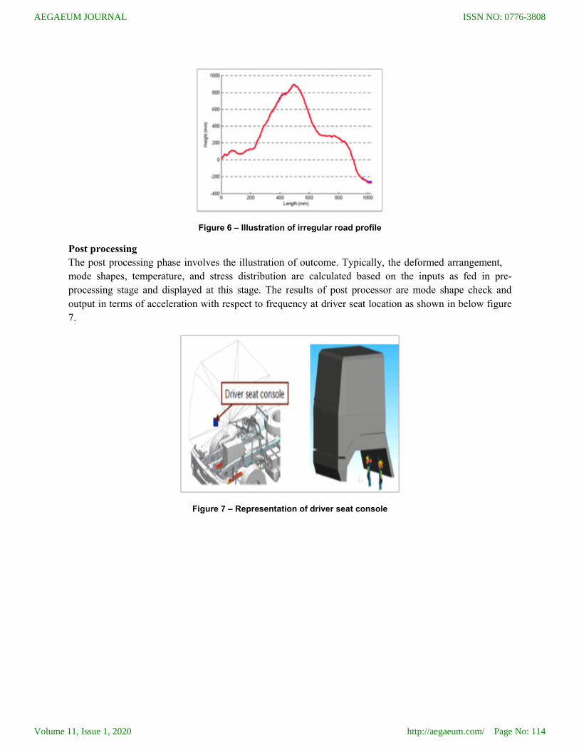
Figure 6 – Illustration of irregular road profile
Post processing
The post processing phase involves the illustration of outcome. Typically, the deformed arrangement,
mode shapes, temperature, and stress distribution are calculated based on the inputs as fed in pre-
processing stage and displayed at this stage. The results of post processor are mode shape check and
output in terms of acceleration with respect to frequency at driver seat location as shown in below figure
7.
Figure 7 – Representation of driver seat console
ISSN NO: 0776-3808
http://aegaeum.com/ Page No: 114
AEGAEUM JOURNAL
Volume 11, Issue 1, 2020

VI. RESULT & INFERENCE
Analysis of longitudinal vibration (To & fro - X axis)
Figure 8 – Comparison of vibration in X axis
Inference:
Analysis completed and comparison is as per above figure 8. Overall there is an improvement seen in
suspended cab mount. Particularly within the observable range of 10 to 15Hz, 25% of improvement
observed with suspended cab mount in X-axis.
Analysis of lateral vibration (Side wards - Y axis)
Figure 9 – Comparison of vibration in Y axis
Inference:
Analysis completed and comparison is as per above figure 9. Increased acceleration observed in
suspended cab mount, because force is acting on lateral direction. This is due to the damper observing the
energy only in axial (vertical) direction. This can be improved by stiffening the rubber hardness.
ISSN NO: 0776-3808
http://aegaeum.com/ Page No: 115
AEGAEUM JOURNAL
Volume 11, Issue 1, 2020

Analysis of vertical vibration (Z axis)
Figure 10– Comparison of vibration in Z axis
Inference:
Analysis completed and comparison is as per above figure 10. Overall there is an improvement seen in
suspended cab mount. Major body resonance in response to Z-axis vibration exists at around 11 to 14 Hz,
where response associated with the mechanical characteristics of the torso and spinal column.Particularly
within the observable range of 10 to 15Hz, 28% of improvement observed with suspended cab mount in
Z- axis. This would be highly beneficial in improving the ride, resulting in reduced vertical movements.
VII. SUMMARY & CONCLUSION
Summary:
With the existing rigid cab mount arrangement, it is observed that vertical & fore-aft acceleration on
different locations cab suspension induces vibration that causes discomfort.The proposed cab suspension
ride clearly indicating that, there is a ~25 % improvement when compared to existing arrangement. This
proposed cab suspension will improve the ride comfort and reduce the fatigue level for the drivers. This
will helps to increase the vehicle productivity, reduction of Vehicle turnaround time and more
profitability to the customers.
VIII. CONCLUSION
Comparison of fixed cab mount and suspended cab mount study carried out. Overall the acceleration for
the suspended cabin is reduced by ~25% as compared to fixed cab mount. In suspended cabin damper is
introduced and energy is observed by the damper that filters out unnecessary vibrations to driver.The
influence of damper is very much helpful for the cabin ride comfort and reduce the fatigue level for the
drivers. Improved cab suspension will helps to increase the vehicle productivity, reduction of vehicle
turnaround time and more profitability to the customer.
ISSN NO: 0776-3808
http://aegaeum.com/ Page No: 116
AEGAEUM JOURNAL
Volume 11, Issue 1, 2020

Challenges faced:
With the introduction of cabin suspension, it is observed that there is huge improvement in X and Z axis.
However the Y axis has more vibration than the earlier limit.This is due to the increased roll of the
vehicle which is allowed by the cabin damper, that allows articulation in Y direction.
REFERENCES
1. Soliman, A (2008) "Improvement of the Truck Ride Comfort Via Cab Suspension," SAE Technical Paper 2008-01-1148, 2008, doi: 10.4271/2008-01-1148.
2. L. Segel T. Gillespie, L.Schneider, K. “ Campbell Sate of the knowledge review: Relationship of truck ride vibration to highway safety” Contract DTFH61-81 -C-00083
3. K.Chinna Maddaiah , D.Venkat Ratnam, K.Nagendr Kumar, Dr.A.Siva Kumar, A.Yesu Venkata Ravi Kumar “Design and Analysis of Automated Truck Cabin Suspension System” International Journal of Engineering Sciences and Research Technology
4. Rajan, V. and Deshmukh, C., "Cab Suspension Optimization Using Matlab," SAE Technical Paper 2013-26-0147, 2013, doi:10.4271/2013-26-0147.
5. Fitness Hazard Evaluation of Whole-body Vibration by ISO 2631-5 and ISO 2631-1 for Operators of Agricultural Tractors and Recreational Vehicles, 2013
ISSN NO: 0776-3808
http://aegaeum.com/ Page No: 117
AEGAEUM JOURNAL
Volume 11, Issue 1, 2020