Study Group Report: Plate-fin Heat Exchangers: AEA Technology · Study Group Report: Plate-fin Heat...
7
Study Group Report: Plate-fin Heat Exchangers: AEA Technology The problem under study concerned the apparent discrepancy between a series of experiments using a plate fin heat exchanger and the classical theory of Nusselt. A plate fin heat exchanger involves the flow of a stream of condensing nitrogen vapour in one flow channel and a counterflowing stream of liquid nitrogen in an adjacent flow channel. The liquid nitrogen is at a lower temperature and pressure and boils. The classical theory of Nusselt treats the flow of the condensing vapour using lubrica- tion theory. A liquid film of condensate forms on the walls of the flow channel, and drains under gravity. As the flow continues along the channel, further condensation occurs and the flux of liquid increases (figure 1). Simple lubrication theory analysis suggests that the mass flux of the liquid per unit width on a flat plate is This may be used to determine the quality, Q, which i~ a measure of the vapour flux divided by the total flux. where M is the total mass flux. Note the quality may alternatively be defined as a thermo- dynamic quality, in which case the ratio of the enthalpy (rather than mass) fluxes is used in the definition, with the liquid and vapour enthalpies being evaluated at the condensation temperature. The relationship between the quality and the mass flux of liquid enables one to deter- mine the heat transfer coefficient as a function of the quality. The heat transfer through the liquid film on the walls has the form, approximately, where T; is the condensation temperature of the vapour and Tw is the wall temperature, and K is the thermal conductivity. The film thickness h may be recast in terms of the quality, using the above analysis, to yield the result This simple theory was applied to understand the variation of the heat transfer coeffi- cient with quality along one of the rectangular plate fin passages in a test heat exchanger at 1
Transcript of Study Group Report: Plate-fin Heat Exchangers: AEA Technology · Study Group Report: Plate-fin Heat...
Study Group Report: Plate-fin Heat Exchangers: AEA Technology
The problem under study concerned the apparent discrepancy between a series ofexperiments using a plate fin heat exchanger and the classical theory of Nusselt. A platefin heat exchanger involves the flow of a stream of condensing nitrogen vapour in one flowchannel and a counterflowing stream of liquid nitrogen in an adjacent flow channel. Theliquid nitrogen is at a lower temperature and pressure and boils.
The classical theory of Nusselt treats the flow of the condensing vapour using lubrica-tion theory. A liquid film of condensate forms on the walls of the flow channel, and drainsunder gravity. As the flow continues along the channel, further condensation occurs andthe flux of liquid increases (figure 1).
Simple lubrication theory analysis suggests that the mass flux of the liquid per unitwidth on a flat plate is
This may be used to determine the quality, Q, which i~ a measure of the vapour fluxdivided by the total flux.
where M is the total mass flux. Note the quality may alternatively be defined as a thermo-dynamic quality, in which case the ratio of the enthalpy (rather than mass) fluxes is used inthe definition, with the liquid and vapour enthalpies being evaluated at the condensationtemperature.
The relationship between the quality and the mass flux of liquid enables one to deter-mine the heat transfer coefficient as a function of the quality. The heat transfer throughthe liquid film on the walls has the form, approximately,
where T; is the condensation temperature of the vapour and Tw is the wall temperature,and K is the thermal conductivity. The film thickness h may be recast in terms of thequality, using the above analysis, to yield the result
This simple theory was applied to understand the variation of the heat transfer coeffi-cient with quality along one of the rectangular plate fin passages in a test heat exchanger at
1
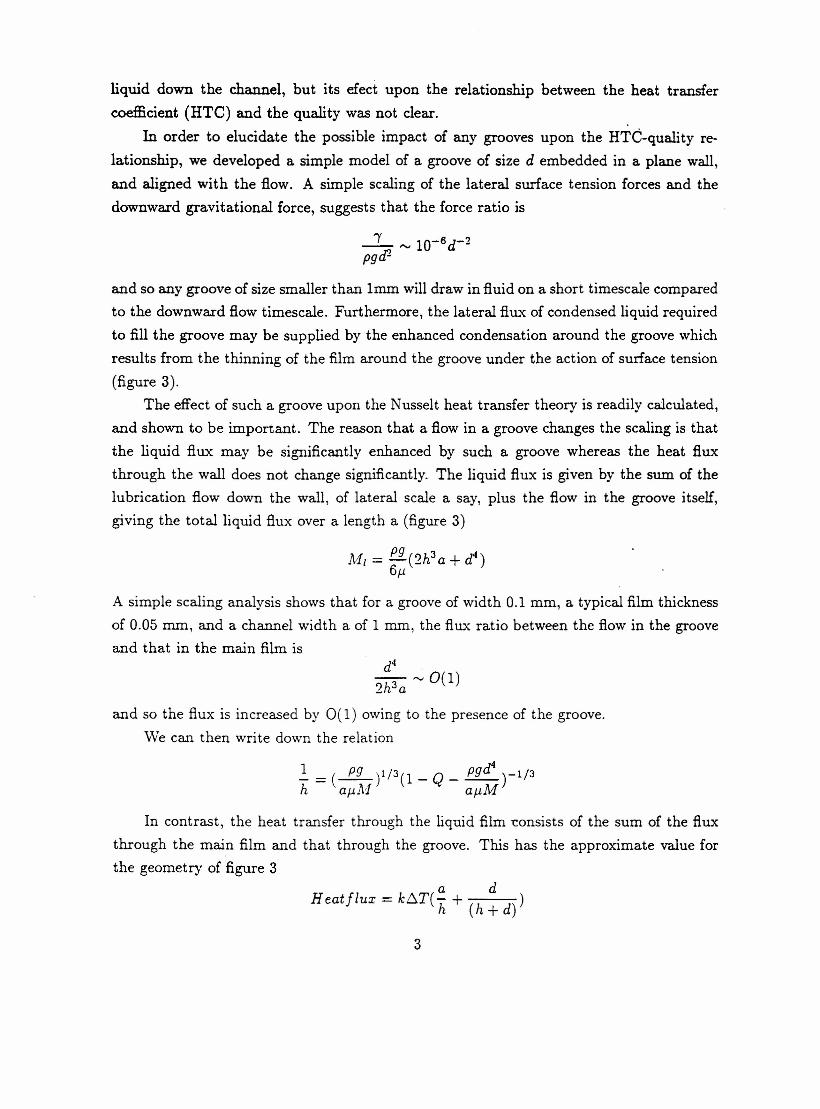
Harwell. The theory was adapted to include the effects of the geometry of the rectangularcavity and the reduced efficiency of the secondary fins, which are not directly in contactwith the counterflowing channel. However, in spite of these corrections to the simple the-ory, the variation of the experimental heat transfer coefficients with quality differed fromthe scaling suggested above (figure 2). At high flow rates the dimensionless heat transfercoefficient varied somewhat more slowly than predicted by the Nusselt scaling, while atlow flow rates the heat transfer coefficient decreased more rapidly than predicted by theNusselt theory. The scaling parameter, which includes the effect of the geometry may befound from the data at imtermediate flow rates (figure 2).
At the study group, various explanations as to the source of the discrepancy betweenthe Nusselt theory and the data were explored. Two approaches taken were to assess thedata collection method and to assess the relevance of the model to the experiments.
Experimental assessment.The quality is calculated by measuring the heat flux through the walls of the channel
and then assuming that this heat flux is supplied by the latent heat released on condensa-tion of the vapour. Therefore, at any distance down the pipe, the total flux of condensedvapour may be estimated.
However, in analysing the data collection methods, it was found that there is somesuperheating of the nitrogen vapour on entry to the channel. This superheat remains inthe vapour for some time, and affects the estimate of the point at which condensationoccurs since the superheat is conducted through the wall in addition to the latent heat.In turn this affects the estimate of the quality. However, from the enthalpy balance, thissuperheating only amounts to a quality error of a few percent.
Further, it was found that the heat flux in the wall was not in fact constant but variedsignificantly near the entry point. The heat flux measurements in the wall were quite farapart, and did not seem sufficient to resolve this variation and thereby accurately estimatethe total heat flux through a given length of the wall. Indeed in some experiments, onlyone or two thermocouples were located in this entry region. One conclusion of the studygroup is that the accuracy of these estimates could be checked.
Theoretical Assessment.In addition, during the study group week, we examined the assumptions implicit in
the Nusselt theory, and their relevance to the flow in question. A major issue which wasaddressed was the role of any indentations in the walls, as arise for example near sitesof brazing between adjacent channel walls. In such narrow grooves, the action of surfacetension is to fill the groove with fluid, and thereby possibly create a flow path of lowerresistance than on the smoother walls of the flow channel. This can increase the flux of
2
liquid down the channel, but its efect upon the relationship between the heat transfercoefficient (HTC) and the quality was not clear.
In order to elucidate the possible impact of any grooves upon the HTC-quality re-lationship, we developed a simple model of a groove of size d embedded in a plane wall,and aligned with the flow. A simple scaling of the lateral surface tension forces and thedownward gravitational force, suggests that the force ratio is
and so any groove of size smaller than Irnm will draw in fluid on a short timescale comparedto the downward flow timescale. Furthermore, the lateral flux of condensed liquid requiredto fill the groove may be supplied by the enhanced condensation around the groove whichresults from the thinning of the film around the groove under the action of surface tension(figure 3).
The effect of such a groove upon the Nusselt heat transfer theory is readily calculated,and shown to be important. The reason that a flow in a groove changes the scaling is thatthe liquid flux may be significantly enhanced by such a groove whereas the heat fluxthrough the wall does not change significantly. The liquid flux is given by the sum. of thelubrication flow down the wall, of lateral scale a say, plus the flow in the groove itself,giving the total liquid flux over a length a (figure 3)
A simple scaling analysis shows that for a groove of width 0.1 mm, a typical film thicknessof 0.05 mm, and a channel width a of 1 mm, the flux ratio between the flow in the grooveand that in the main film is
and so the flux is increased by O(1) owing to the presence of the groove.We can then write down the relation
In contrast, the heat transfer through the liquid film "Consistsof the sum of the fluxthrough the main film and that through the groove. This has the approximate value forthe geometry of figure 3
a dHeatflux = kt:::.T(-;;, + (h+d))
3

Now the ratio of the heat flux through the groove and through the film proper is
(d+h)a"'O,ldh
and so the heat flux is not significantly altered by the presence of the liquid filled groove.As a result, the heat flux has the approximate value
K6TaHeatflux = h
and the heat transfer coefficient scales as t(l + O( (d!~)a».Using the revised formula for the liquid flux, we see that the heat transfer coefficient
is related to the quality by the scaling
The term on the right hand side is of some import, as shown above, and correspondsto the enhancement of the liquid flux owing to the presence of the grooves. In figure 4, weshow how this factor differs from the classical Nusselt theory in which the scaling is simply(1 - Q)-1/3. Note that the effect this correction is greatest at low flow rates for which theliquid in the film constitutes a large fraction of the total flux.
Experimental Design.A further feature was noted about the present experimental configuration. This sheds
some light upon the sensitivity of the apparatus to detect changes in the heat transfercoefficient with fin blade shape. It was identified that with the present experimentaldesign, most of the temperature drop between the condensing vapour and the boilingliquid in adjacent flow channels actually occurs in the metal dividing the two flow channelsrather than in the liquid film of condensate on the wall of the channel. In particular, if webalance the flux of heat through the wall with that through the liquid film, then
T.' Tc - TWT.' Tw - n..1'../ h = .l'-a h
w
where hw is the thickness of the wall and Tb is the boiling temperature on the far side ofthe wall. Since the wall thickness in the experimental set-up is approximately 6 mm, and
the typical film thickness is 0.1 mm, then the temperature drop across the wall is about10 times larger than that across the film of condensed vapour. As a result, the heat flux
4

across the walls of the channel is insensitive to small changes in the mean thickness ofthe liquid film as the geometry of the channel is varied for example, since the heat fluxis determined by the temperature drop across the wall. For a given position ~ong theflow channel, in each experiment a comparable mass of liquid will condense in order tosupply the heat flu."{through the wall. As a result, the quality at a given location alongthe wall will be relatively insensitive to differences in the detailed channel geometry, andit is difficult to accurately compare the efficiency of different channel designs.
In the real systems, the wall thickness is much smaller, and the heat flux is thereforemore sensitive to changes in the thickness of the liquid film, since more of the temperaturedifference between the boiling and condensing flows occurs across the condensed liquidfilm.
A different approach might be to examine the properties of the flow at various pointsalong the flow channel, by arranging a series of different length flow channels in series, andsampling the output from each channel.
A number of questions emerge from this report, including:(i) is there a critical heat flux ?(ii) what size/shape of groove is best?(iii ) can models be tested using the existing experimental data?
5

~<---- Q. ----~)
\ / kur .f!;,w-
\ "" "/~ 1~ (asJ~it,<, " NuJJ-di ~)" "" .•....•
•......• •......•
"
Q

~:L.z->
~~~
~-'-_ .....J2-0
T..•...•cQ)
u
---- -:::0-1 K uncertainty estimate in raw 6.T'+-'"-Q)ouL-Q)'+-VlCUL-
-+- -
e e~/-Vg increasing
•....'::ln-.c·-
ocoVl~ (1-3J::. I
.-(J
I-
\:sNusselt-------
..-
McNaught (1987) /~c = (1 7 I) 6. n = 0 -22In t::qL-Gtion t. I
o 2 ..
Vg,gas velocity (m/s~
+ >2-0
rJ1<Vg<2
~ <1-0-
PLAII'J FI N
NITROGEN
ALL DATA:
2 - 6 bar, 17- 90 kg I m2 s
ohigh shear region where
( d P ) > 1-2 x 1. (d P )dz T g dz TV
o
;1;s~4i~~)------
.•.••.•.•... ------- ---"
0-11 I I I I I I I I I I I __L.J__~_--' I I
50 100 200 500 1000 2000-
~ film Reynolds number f1~r-