Studio Air Journal 359754
68
ADS: AIR JOEL POLYCHRONOPOULOS 3 5 9 7 5 4 T:FINNIAN WARNOCK-HANNES MCNAMARA
-
Upload
joel-polychronopoulos -
Category
Documents
-
view
228 -
download
0
description
year 3 studio 3 sem2 2012 journal by Joel Polychronopoulos
Transcript of Studio Air Journal 359754
ADS: AIR JOEL POLYCHRONOPOULOS3 5 9 7 5 4T:FINNIAN WARNOCK-HANNES MCNAMARA

a special thanks to group partners:
nicholas moloney 359519keli muraray 517928
and tutors:
finnian warnockhannes mcnamara
it has been a rewarding pleasure.
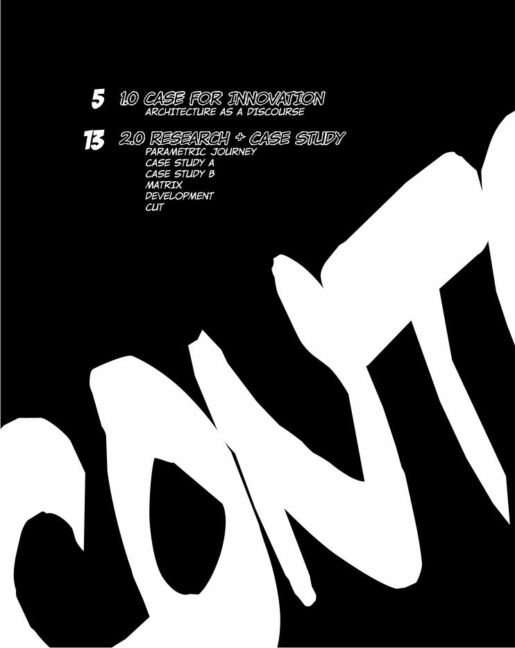
CONTENTS
1.0 CASE FOR INNOVATION ARCHITECTURE AS A DISCOURSE
2.0 RESEARCH + CASE STUDY PARAMETRIC JOURNEY CASE STUDY A CASE STUDY B MATRIX DEVELOPMENT CUT
5
13
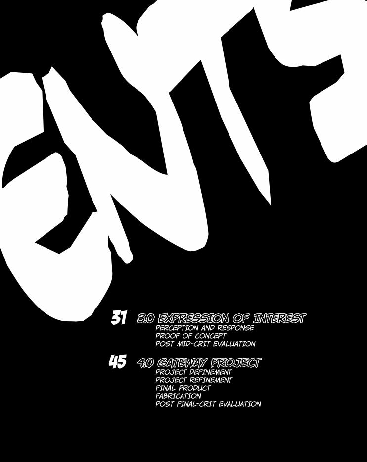
CONTENTS
3.0 EXPRESSION OF INTEREST PERCEPTION AND RESPONSE PROOF OF CONCEPT POST MID-CRIT EVALUATION
4.0 GATEWAY PROJECT PROJECT DEFINEMENT PROJECT REFINEMENT FINAL PRODUCT FABRICATION POST FINAL-CRIT EVALUATION
31
45

1.0 CASE FOR INNOVATION
5
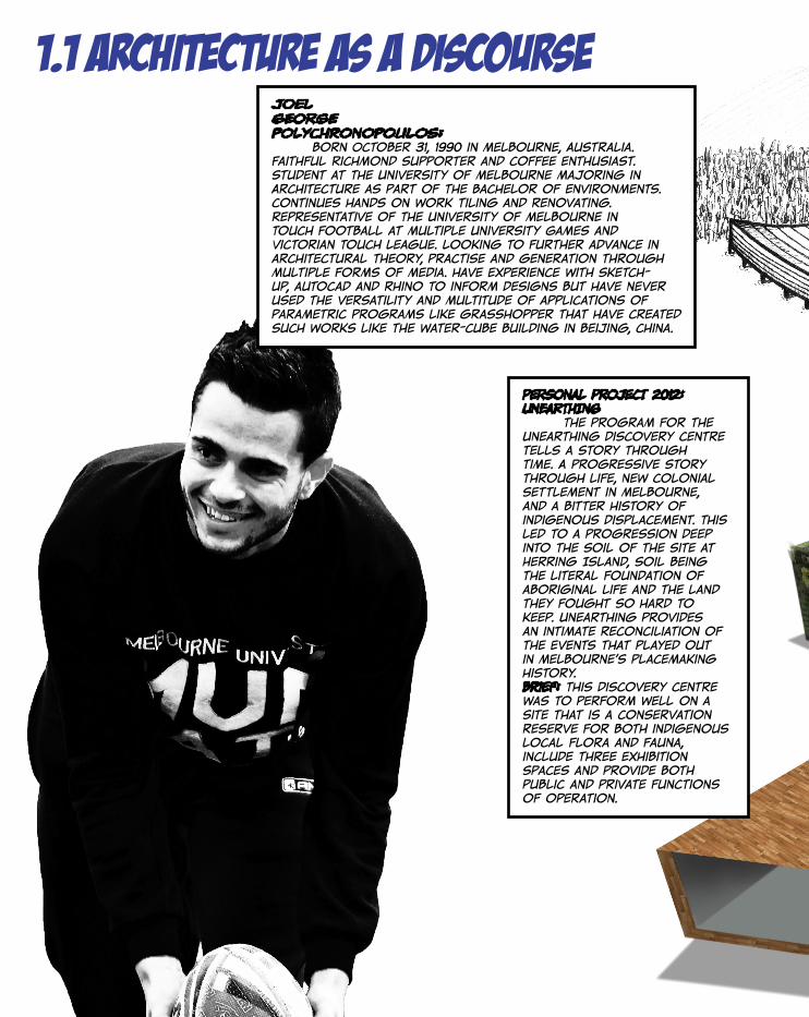
JOEL GEORGEPOLYCHRONOPOULOS: born October 31, 1990 in Melbourne, Australia. Faithful Richmond supporter and coffee enthusiast. Student at The University of Melbourne majoring in Architecture as part of the Bachelor of Environments. Continues hands on work tiling and renovating. Representative of The University of Melbourne in Touch Football at multiple University Games and Victorian Touch League. Looking to further advance in architectural theory, practise and generation through multiple forms of media. have experience with sketch-up, autocad and rhino to inform designs but have never used the versatility and multitude of applications of parametric programs like grasshopper that have created such works like the water-cube building in beijing, china.
PERSONAL PROJECT 2012: UNEARTHING The program for the Unearthing Discovery Centre tells a story through time. A progressive story through life, new Colonial settlement in Melbourne, and a bitter history of indigenous displacement. This led to a progression deep into the soil of the site at Herring Island, soil being the literal foundation of aboriginal life and the land they fought so hard to keep. Unearthing provides an intimate reconciliation of the events that played out in Melbourne’s placemaking history. brief: This Discovery centre was to perform well on a site that is a conservation reserve for both indigenous local flora and fauna, include three exhibition spaces and provide both public and private functions of operation.
1.1 architecture as a discourse
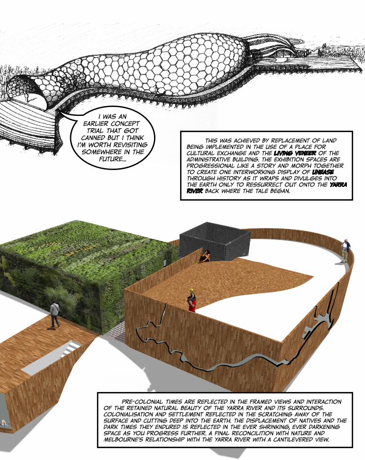
this was achieved by replacement of land being implemented in the use of a place for cultural exchange and the living veneer of the administrative building. The Exhibition spaces are progressional like a story and morph together to create one interworking display of unease through history as it wraps and divulges into the earth only to ressurrect out onto the Yarra River back where the tale began.
Pre-colonial times are reflected in the framed views and interaction of the retained natural beauty of the Yarra River and its surrounds. Colonialisation and settlement reflected in the scratching away of the surface and cutting deep into the earth. The displacement of natives and the dark times they endured is reflected in the ever shrinking, ever darkening space as you progress further. A final reconcilition with nature and Melbourne’s relationship with the Yarra River with a cantilevered view.
i was an earlier concept trial that got
canned but i think i’m worth revisiting somewhere in the
future...

Manning, Laura n.d., Institut du Monde Arabe, photograph, viewed 8 November 2012, <http://www.archdaily.com/162101/ad-classics-institut-du-monde-arabe-jean-nouvel/4124717255_7d2a3153ac_oboonj/>.
Manning, Laura n.d., Institut du Monde Arabe, photograph, viewed 8 November 2012, <http://www.archdaily.com/162101/ad-classics-institut-du-monde-arabe-jean-nouvel/2821962571_322a7acbcc_olaura-manning/>.
Sean nouvel’s institut du monde arabe (ima), 1981-87, paris france. This building, that catapulted sean nouvel’s fame and career, houses the arab world institute (awi). it was part of the high-tech and late modernism style that saw many of its counterparts being structurally expressive or expressing the technology of the time in full public view. this building took this ideal one step further to visually include not only the most current structural technology but also the most advanced digital technology in its facade. the south-west facade shown is an unhindered rectangular glass curtain wall which despite its simple and regular form, is in stark contrast to its opposite facade that mimics the very curves of la seine river adjacent. behind the glass is an arrayed system of 240 geometric mechanical motifs. each square motif comprises motorised irises that control and filter the amount of light and heat that enter the building as a sophisticated mashrabiya that reflets the very ingenuity of islamic culture that the building represents. it has proved to be a very successful building, but not without its problems.
“with more motorised parts comes more that
could go wrong and more that will eventually
need fixing”-kevin farley 2006, year 10 engineering
teacher
http://cherilucas.files.wordpress.com/2011/03/jewish-museum-exterior-berlin.jpg
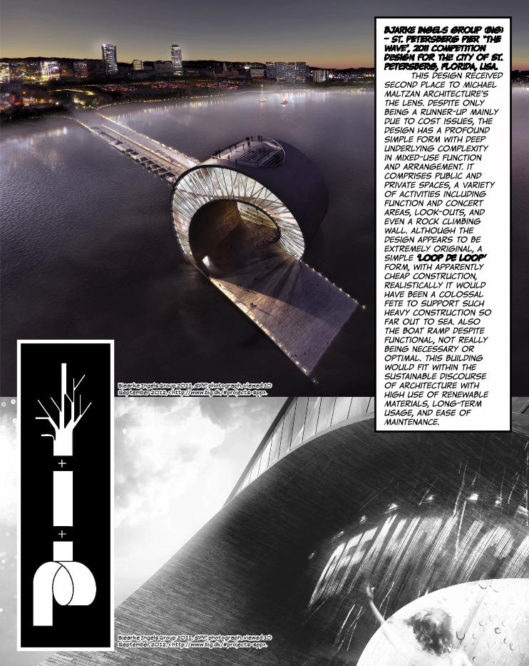
bjarke ingels group (big) - st. petersberg pier “the wave”, 2011 competition design for the city of st. petersberg, florida, usa. this design received second place to Michael Maltzan Architecture’s The Lens. despite only being a runner-up mainly due to cost issues, the design has a profound simple form with deep underlying complexity in mixed-use function and arrangement. it comprises public and private spaces, a variety of activities including function and concert areas, look-outs, and even a rock climbing wall. although the design appears to be extremely original, a simple ‘loop de loop’ form, with apparently cheap construction, realistically it would have been a colossal fete to support such heavy construction so far out to sea. also the boat ramp despite functional, not really being necessary or optimal. This building would fit within the sustainable discourse of architecture with high use of renewable materials, long-term usage, and ease of maintenance.
Bjearke Ingels Group 2011, SPP, photograph, viewed 10 September 2012, < http://www.big.dk/#projects-spp>.
Bjearke Ingels Group 2011, SPP, photograph, viewed 10 September 2012, < http://www.big.dk/#projects-spp>.
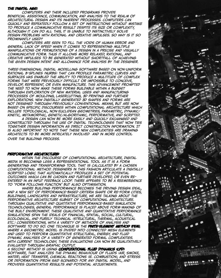
the digital age: Computers and their included programs provide beneficial assistance, communication, and analysis to the realm of architectural design and its inherent processes. Computers can quickly and repeatedly follow a set of instructions without mistake to produce a communicative result despite its size or complexity, Although it can do all this, it is unable to instinctively solve design problems with rational and creative impulses. So why is it so prominantly used? Computers are seen to fill the voids of human error and general lack of speed when it comes to representing multiple manipulations or permutations of a design in a precise and visually communicative form. Thus it allows more relaxed, rational, and creative impulses to be generated without shortfall of achieving the given design intent and allowance for analysis by the designer.
Three-dimensional digital modelling software based on Non-Uniform Rational B-Splines (NURBS) that can produce parametric curves and surfaces has enabled the ability to produce a multitude of complex forms that were previously difficult or impossible to conceive, develop, represent, or even manufacture. This advancement prompted the need to now make these forms buildable within a budget through exploration of new material uses and manufacturing processes of moulding, lasercutting, 3D printing and further explorations. New digitally generated 3D shapes and forms are not designed through previously conventional means, but are now based on specific discourses within computational architecture which include topological, non-euclidean geometries, parametric, dynamic/kinetic, metamorphic, genetic/algorithmic, performative, and scripted. A design can now be more easily and quickly exchanged and constructed through the use of digital technologies that now ties together design information as direct construction information. It is also important to note that these new complexities are drawing architects to be more intricately involved and in more control
over the building process.
performative architecture: within the discourse of computational architecture, digital media is becoming less a representational tool as it is a form generating and transforming tool that is calculated by a chosen computational method. designers in this fashion articulate a digitally scripted logic that automatically produces a set of potential outcomes which can be chosen and further developed, or even re-entered in an input feedback loop. there appears to be a reemergence to “form follows function” but also optimisation. where building performance becomes the driving design ideal, and a new set of performance-based criteria shape or re-form cities, buildings, landscapes and infrastructure, we are talking about the performative architecture subset of computational architecture. through qualitative and quatitative performance-based simulation technologies, general performance is placed above form-making of the built environment. these qualitative and quantitative performance simulations span the ideals of financial, spatial, social, cultural, ecological, and purely technical (structural, thermal, acoustical etc.) considerations, with a variety of methods of analysis and software to do so. one technique is the finite-element method (fem), where a geometric model is divided into connected mesh elements and used to perform quantitative structural, energy, and fluid dynamic analyses of a variety of generated formal complexities. with current technology, these evaluations can now be qualitatively evaluated through graphic output.a second method is using computational fluid dynamics (cfd) software, that analyzes the dynamic behaviour of fluids (air, smoke, water), heat transfer, chemical reactions (ie. combustion), and stress or deformation (from said scenario) for any digital model, and provides quantitative results and potential adjustments.

Hawkes, Jason 2012, Night aerial view over Swiss Re Tower, and the Lloyds Building, City of London, photograph, viewed 10 September 2012, < http://www.theatlantic.com/infocus/2012/05/views-from-the-night-sky-london-and-the-uk/100298>.
30 ST MARY AXE, LONDON

2.0 research+ case study
13
experience with parametric theory: with little experience and knowledge of parametric design theory, processes and applications, it has been an insightful three weeks that has really provided a world of answers to the technology available today and what can be achieved with them, through research into projects that have only been realised with this technology. It has even provided answers to questions posed in earlier years of not knowing how to resolve complicated issues, that now could be easily resolved with further development of parametric software knowledge and practise. with little experience with the software still, it is difficult to envisage its full potential and the aspects of parametricism are still vague, but it appears it will be an exciting and insightful journey. one that has been long awaited...
group argument; with keli murray and nicholas moloney: in response to the competition for the wyndham city gateway project with our expression of interest, it has been decided that a focus of perception will be a starting point in informing our idea generation towards a suitable solution for an installation to suit the needs of the wyndham city council. we believe that perception and interaction are EXTREMELY RELEVANT TO SUCH AN INSTALLATION AS IT MUST ENGAGE WITH THE VIEWERS WHICH WOULD BE DRIVERS AND PASSENGERS IN AUTOMOBILES PASSING BY AT 100KM/H, AND THUS MUST BE EXPERIENTIAL AND MEMORABLE IN A VERY SHORT TIME. THIS FOCUS ALSO ALLOWS AN INTERESTING APPROACH TO DISCOVER THE POTENTIAL OF PARAMETRIC DESIGN WITH AN OBJECTIVE OTHER THAN AESTHETICS. WITH a PASSING VIEW can ALSO GIVE AN EVER CHANGING PRIVileged point of view which can be used to manipulate what the viewer sees at any given time, much like the faulders studio design proposal for the museum of contemporary art. in this way the installation could be static and yet still transient and animate. this animation could be solitarily held by the installtion itself or by passive means like shadow creation that moves and reforms as the sun moves. perception can also include the passive means of reacting to stimuli from the immediate environment, even the cars themselves. the key focus will be to create a structure that is visually interactive and animate whilst structurally remaining static.
2.1 “parametric journey”
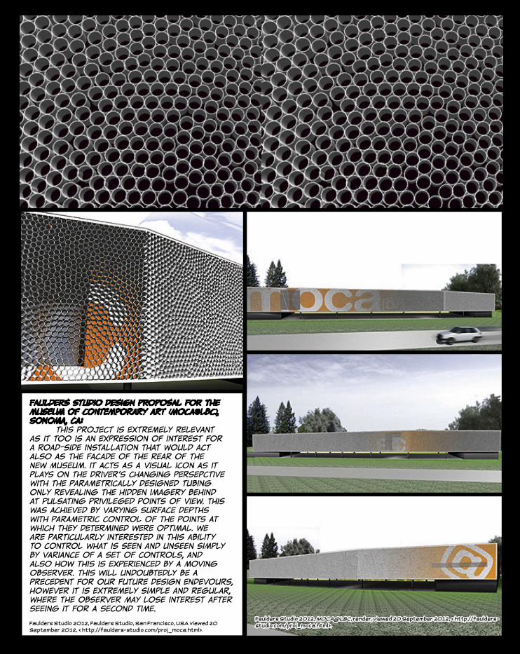
faulders studio design proposal for the museum of contemporary art (moca@lbc), sonoma, ca: this project is extremely relevant as it too is an expression of interest for a road-side installation that would act also as the facade of the rear of the new museum. it acts as a visual icon as it plays on the driver’s changing persepctive with the parametrically designed tubing only revealing the hidden imagery behind at pulsating privileged points of view. This was achieved by varying surface depths with parametric control of the points at which they determined were optimal. we are particularly interested in this ability to control what is seen and unseen simply by variance of a set of controls, and also how this is experienced by a moving observer. this will undoubtedly be a precedent for our future design endevours, however it is extremely simple and regular, where the observer may lose interest after seeing it for a second time.
Faulders Studio 2012, Faulders Studio, San Francisco, USA viewed 20 September 2012, < http://faulders-studio.com/proj_moca.html>.
Faulders Studio 2012, MOCA@LBC, render, viewed 20 September 2012, < http://faulders-studio.com/proj_moca.html>.
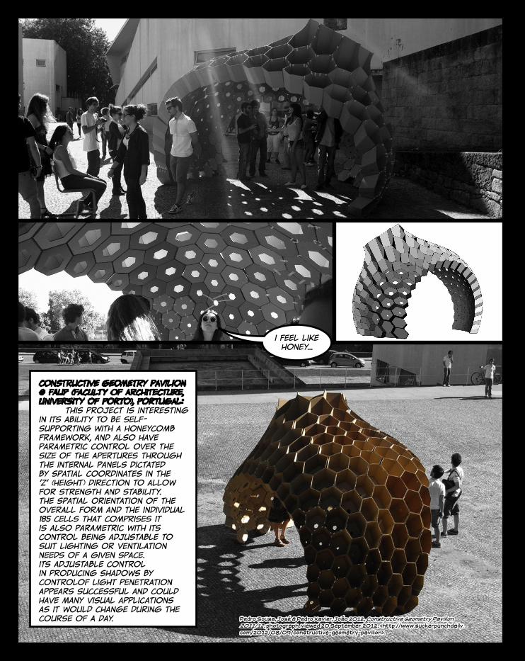
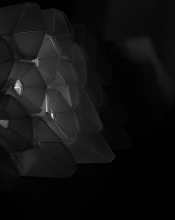
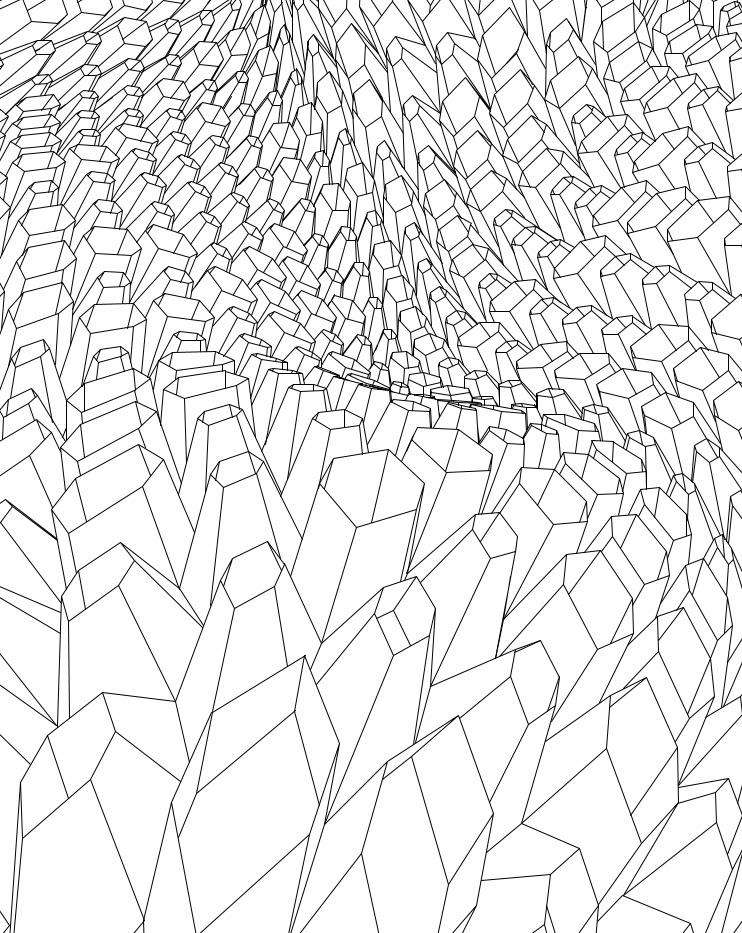
constructive geometry pavilion @ faup (faculty of architecture, university of porto), portugal: this project is interesting in its ability to be self-supporting with a honeycomb framework, and also have parametric control over the size of the apertures through the internal panels dictated by spatial coordinates in the ‘z’ (height) direction to allow for strength and stability. the spatial orientation of the overall form and the individual 185 cells that comprises it is also parametric with its control being adjustable to suit lighting or ventilation needs of a given space. its adjustable control in producing shadows by controlof light penetration appears successful and could have many visual applications as it would change during the course of a day. Pedro Sousa, José & Pedro Xavier, João 2012, Constructive Geometry Pavilion
2011/12, photograph, viewed 20 September 2012, <http://www.suckerpunchdaily.com/2012/08/09/constructive-geometry-pavilion>.
i feel like honey...
Pedro Sousa, José & Pedro Xavier, João 2012, Constructive Geometry Pavilion 2011/12, photograph, viewed 20 September 2012, <http://www.suckerpunchdaily.com/2012/08/09/constructive-geometry-pavilion>.
Pedro Sousa, José & Pedro Xavier, João 2012, Constructive Geometry Pavilion 2011/12, photograph, viewed 20 September 2012, <http://www.suckerpunchdaily.com/2012/08/09/constructive-geometry-pavilion>.
Pedro Sousa, José & Pedro Xavier, João 2012, Constructive Geometry Pavilion 2011/12, photograph, viewed 20 September 2012, <http://www.suckerpunchdaily.com/2012/08/09/constructive-geometry-pavilion>.
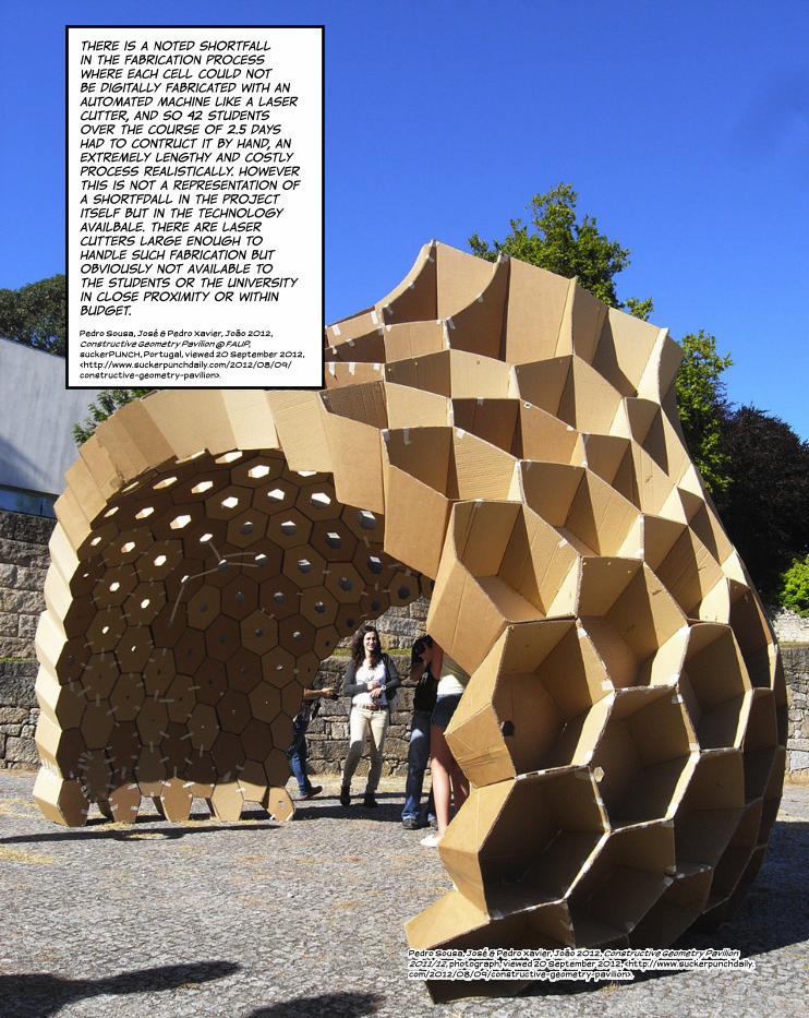
there is a noted shortfall in the fabrication process where each cell could not be digitally fabricated with an automated machine like a laser cutter, and so 42 students over the course of 2.5 days had to contruct it by hand, an extremely lengthy and costly process realistically. however this is not a representation of a shortfdall in the project itself but in the technology availbale. there are laser cutters large enough to handle such fabrication but obviously not available to the students or the university in close proximity or within budget.
Pedro Sousa, José & Pedro Xavier, João 2012, Constructive Geometry Pavilion @ FAUP, suckerPUNCH, Portugal, viewed 20 September 2012, <http://www.suckerpunchdaily.com/2012/08/09/constructive-geometry-pavilion>.
PiracudaGroup 2012, Jimmy Hendrix Wallpaper, Image, viewed 20 September 2012, <http://www.piracudaproject.com/jimi-hendrix-wallpaper>.
“You have to go
on and be crazy. Craziness is like
heaven.”
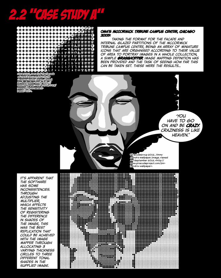
2.2 “case study A”OMA’s McCormick Tribune Campus Center, chicago 2003: taking the format for the facade and internal glazed partitions of the mccormick tribune campus centre, being an array of miniature icons that are organised according to their value of area to portray images in a whole collection, a simple grasshopper image mapping definition has been provided and the task of seeing how far this can be taken set. these were the results...
OMA 2012, Detail of the façade of OMA’s McCormick Tribune Campus Center, image, viewed 20 September 2012, <http://www.wallpaper.com/architecture/resampling-ornament-basel/2417>.
it’s apparent that the software has some inconsistencies. through adjusting the multiplier, which affects the sensitivity of registering the difference in shades of the image, this was the best replication that could be achieved with the image mapper through allocating 3 varying thickness circles to three different tonal shades in the supplied image.
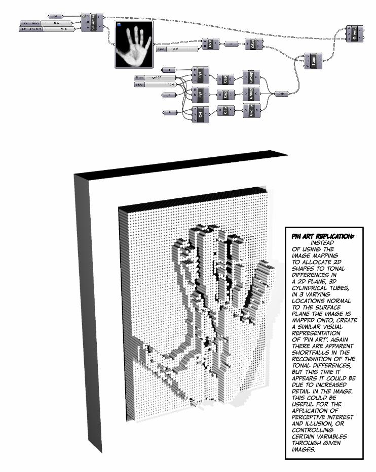
pin art replication: instead of using the image mapping to allocate 2d shapes to tonal differences in a 2d plane, 3d cylindrical tubes, in 3 varying locations normal to the surface plane the image is mapped onto, create a similar visual representation of ‘pin art’. again there are apparent shortfalls in the recognition of the tonal differences, but this time it appears it could be due to increased detail in the image. this could be useful for the application of perceptive interest and illusion, or controlling certain variables through given images.
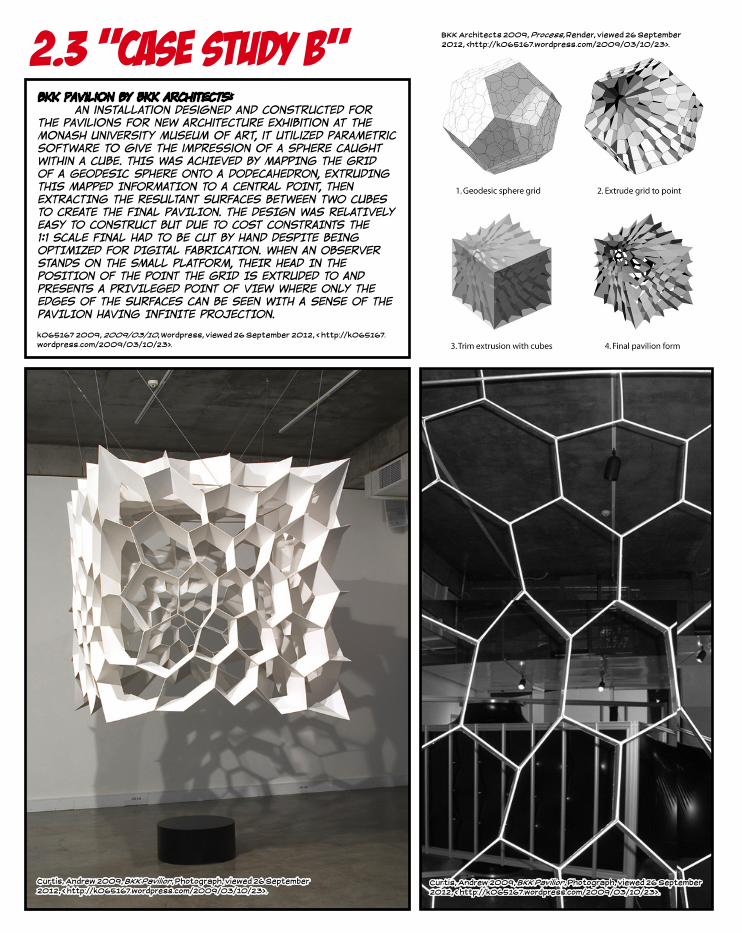
2.3 “case study b”bkk pavilion by bkk architects: an installation designed and constructed for the Pavilions For New Architecture exhibition at the Monash University Museum of Art, it utilized parametric software to give the impression of a sphere caught within a cube. THIS WAS ACHIEVED BY MAPPING THE GRID OF A GEODESIC SPHERE ONTO A DODECAHEDRON, EXTRUDING THIS MAPPED INFORMATION TO A CENTRAL POINT, THEN EXTRACTING THE RESULTANT SURFACES BETWEEN TWO CUBES TO CREATE THE FINAL PAVILION. tHE DESIGN WAS RELATIVELY EASY TO CONSTRUCT BUT DUE TO COST CONSTRAINTS THE 1:1 SCALE FINAL HAD TO BE CUT BY HAND DESPITE BEING OPTIMIZED FOR DIGITAL FABRICATION. WHEN AN OBSERVER STANDS ON THE SMALL PLATFORM, THEIR HEAD IN THE POSITION OF THE POINT THE GRID IS EXTRUDED TO AND PRESENTS A PRIVILEGED POINT OF VIEW WHERE ONLY THE EDGES OF THE SURFACES CAN BE SEEN WITH A SENSE OF THE PAVILION HAVING INFINITE PROJECTION.
k065167 2009, 2009/03/10, Wordpress, viewed 26 September 2012, < http://k065167.wordpress.com/2009/03/10/23>.
Curtis, Andrew 2009, BKK Pavilion, Photograph, viewed 26 September 2012, < http://k065167.wordpress.com/2009/03/10/23>.
BKK Architects 2009, Process, Render, viewed 26 September 2012, <http://k065167.wordpress.com/2009/03/10/23>.
Curtis, Andrew 2009, BKK Pavilion, Photograph, viewed 26 September 2012, < http://k065167.wordpress.com/2009/03/10/23>.
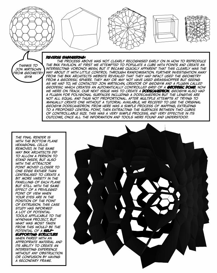
Reverse engineering: the process above was not clearly recognised early on in how to reproduce the bkk pavilion. at first we attempted to populate a cube with points and create an intersecting voronoi mesh, but it became quickly apparent that this clearly was the way about it with little control through randomisation. further investigation away from the bkk architects website revealed that they had infact used the geometry from a geodesic sphere. they may or may not have used grasshopper but seeing as we had to, we contacted jon mirtschin, creator of geogym and a plugin called geodesic which creates an automatically controlled grid of a geodesic dome. now we were on track. our next issue was to create a dodecahedron. geogym also had a plugin for polygonal surfaces including a dodecahedron but the lengths are not all equal and thus not proportional. after multiple attempts at trying to manually create one without a tutorial available, we receded to use the original geogym dodecahedron. from here was a simple process of mapping, extruding to a proposed central point, then extracting the surfaces between two cubes of controllable size. this was a very simple process, and very effective in its outcome, once all the information and tools were found and understood.
the final render is with the bottom plane hexagonal cells removed, in the same way bkk architects did to allow a person to stand inside, but also with the attractor point moved closer to one edge rather than centralised to create a bit more variety in the panelling of each plane but still with the same effect of a privileged point of view when your eyes are in the position of the point of extrusion. this case study has informed a lot of potential tools applicable to the wyndham project, but what was most taken from this would be the potential of a self-supporting structure when paired with an appropriate material and its ability to create an interesting experience without any obstruction or confusion by having a secondary frame.
thanks to jon mirtschin from geometry
gym
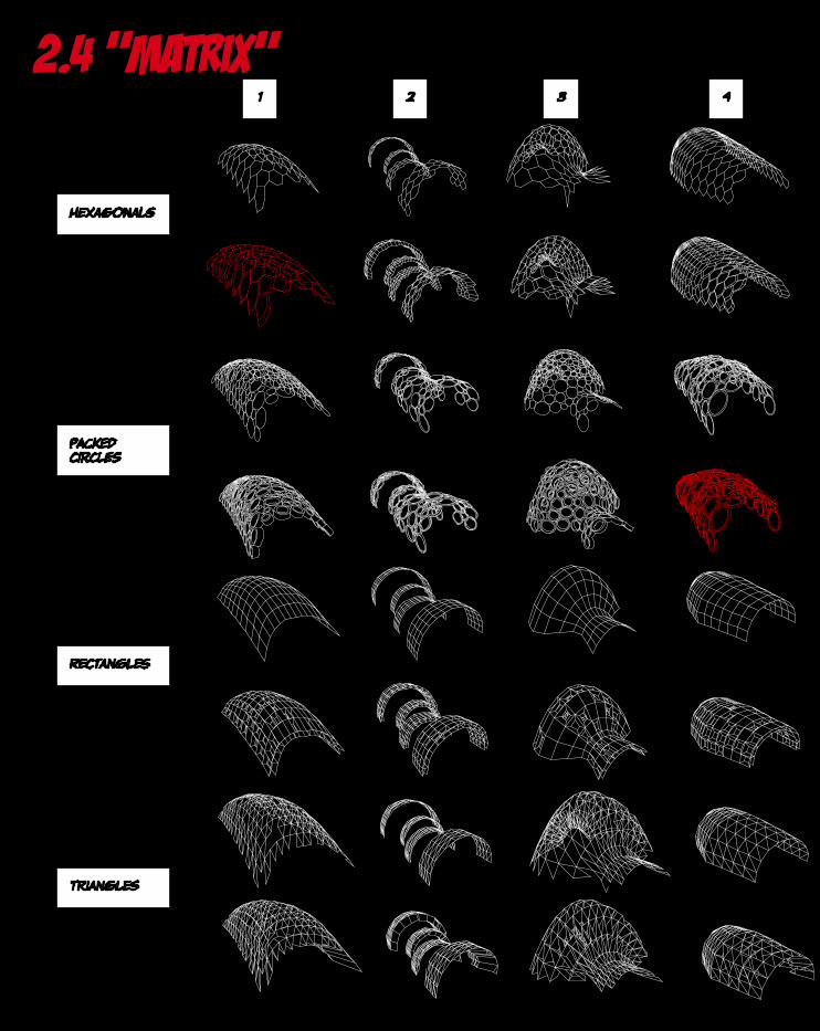
2.4 “matrix”
hexagonals
packed circles
rectangles
triangles
1 2 3 4

5 6 pick of the bunch: the focus of the matrix was to generate as many forms as possible and extract the most vaible options under a set of proposed constraints. our considerations were to use the theme of perception and either control the view of the observer to key areas of interst in wyndham or create an illusive connection to the extrernal surrounds. it quickly became apparent that the city of wyndham being a city of flat grasslands didn’t have much to focus on or towards, therefore the idea came to flip the relationship of the sculpture from internal:out to external:in. we believe we can achieve this through shadow casting whereby external light can be controlled and funnelled inwards through apertures as part of a collection of basic geometry in a cohesive whole. to test this we trialled a variety of basic geometry (triangle, rectangle, circle, hexagon) on a series of different skins, and then extrude this geometry to see what the overall outcome would present and how easily controllable it would be in parametric manipulation and in light funnelling. at first sight in the matrix on skin 1, the hexagon appears a strong viable option as it has its direct proof with the precedent of the bkk pavilion in case study b. as the matrix continues, the circle packing form is extremely aesthetically pleasing with a major cool factor, but the gaps between the circles means less control of apertures and the circles themselves pack randomly to a surface so is again with little control outside of how many and size vfariences. so it fell back to the obvious choice from the start, the hexagonal extrusion form that is structurally sound, has controllable apertures, highly aesthetic, and despite its simplicity, being more complex and easier to appreciate than rectangles or triangles.
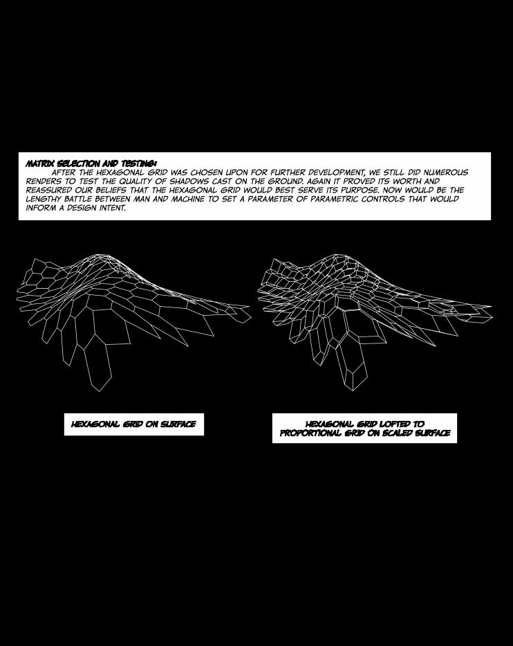
matrix selection and testing: after the hexagonal grid was chosen upon for further development, we still did numerous renders to test the quality of shadows cast on the ground. again it proved its worth and reassured our beliefs that the hexagonal grid would best serve its purpose. now would be the lengthy battle between man and machine to set a parameter of parametric controls that would inform a design intent.
hexagonal grid on surface hexagonal grid lofted to proportional grid on scaled surface
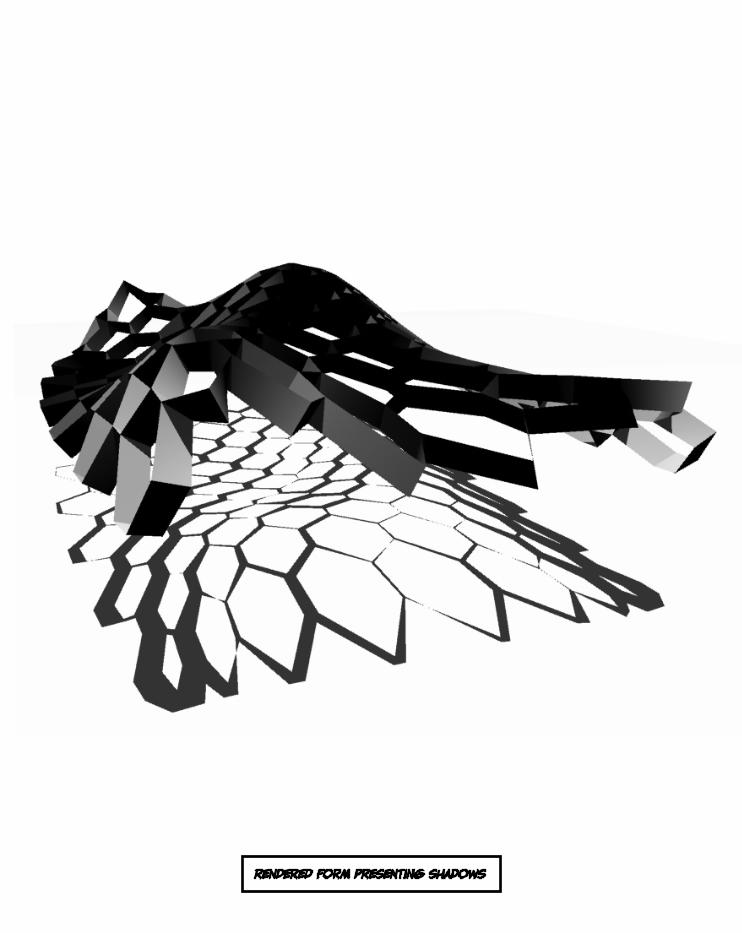
rendered form presenting shadows
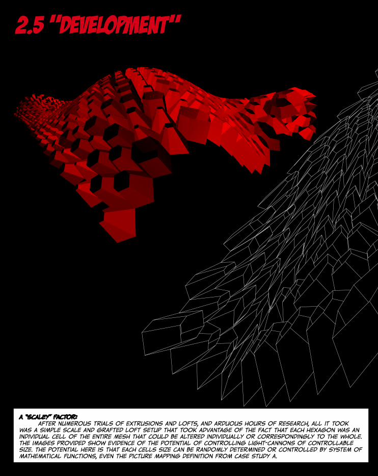
2.5 “development”
a “scaley” factor: after numerous trials of extrusions and lofts, and arduous hours of research, all it took was a simple scale and grafted loft setup that took advantage of the fact that each hexagon was an individual cell of the entire mesh that could be altered individually or correspondingly to the whole. the images provided show evidence of the potential of controlling light-cannons of controllable size. the potential here is that each cells size can be randomly determined or controlled by system of mathematical functions, even the picture mapping definition from case study a.

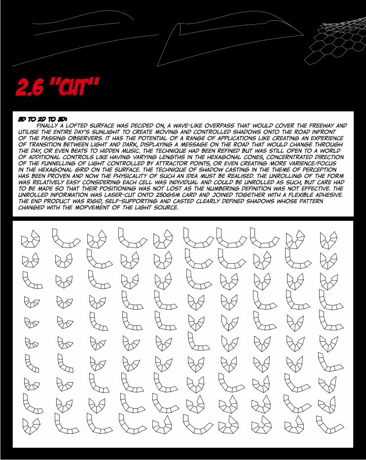
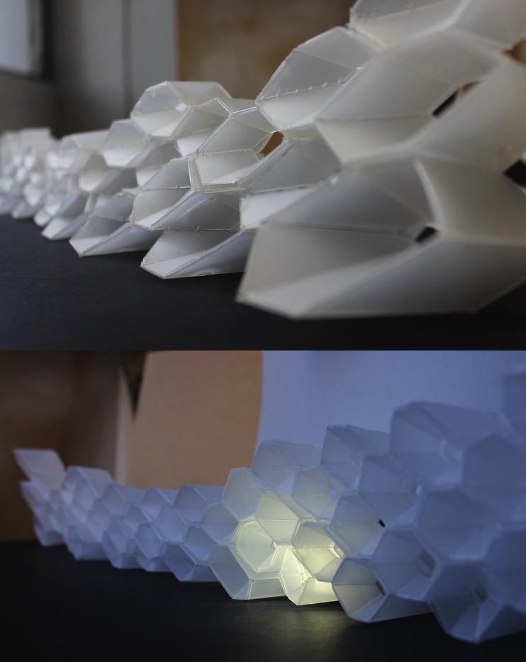
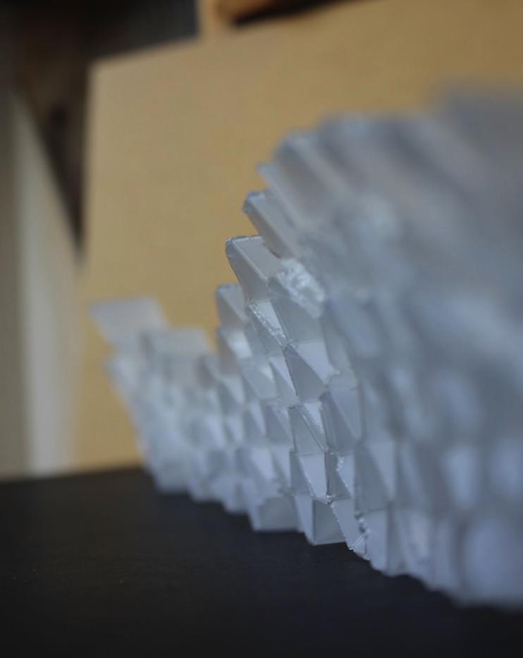
2.6 “cut”3d to 2d to 3d: finally a lofted surface was decided on, a wave-like overpass that would cover the freeway and utilise the entire day’s sunlight to create moving and controlled shadows onto the road infront of the passing observers. it has the potential of a range of applications like creating an experience of transition between light and dark, displaying a message on the road that would change through the day, or even beats to hidden music. the technique had been refined but was still open to a world of additional controls like having varying lengths in the hexagonal cones, concerntrated direction of the funnelling of light controlled by attractor points, or even creating more varience/focus in the hexagonal grid on the surface. the technique of shadow casting in the theme of perception has been proven and now the physicality of such an idea must be realised. the unrolling of the form was relatively easy considering each cell was individual and could be unrolled as such, but care had to be made so that their positioning was not lost as the numbering definition was not effective. the unrolled information was laser-cut onto 250gsm card and joined together with a flexible adhesive. the end product was rigid, self-supporting and casted clearly defined shadows whose pattern changed with the mopvement of the light source.
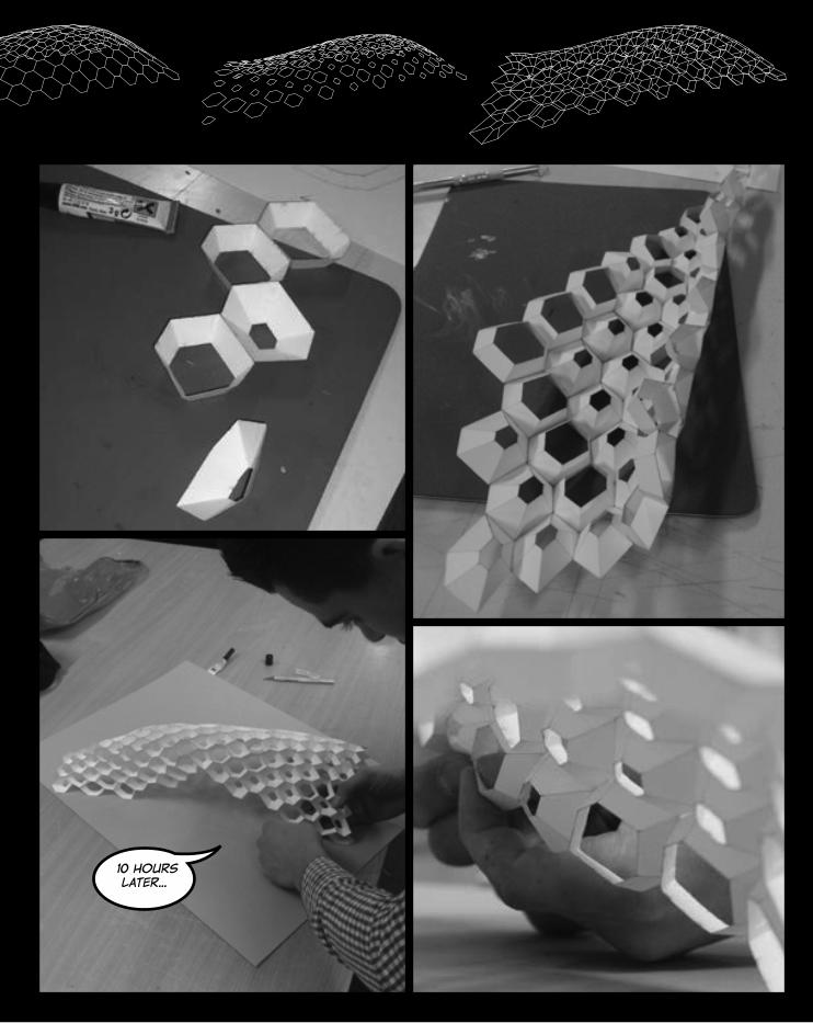
10 hours later...

3.0 expressionof interest
31
Page 5
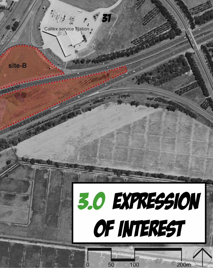
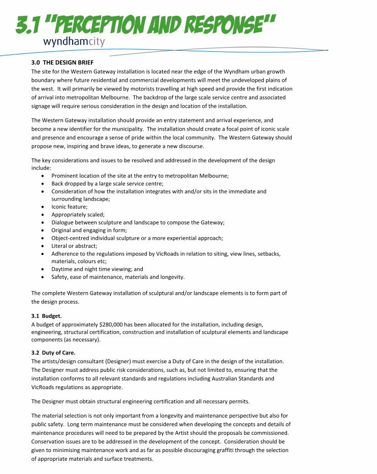
3.0 THE DESIGN BRIEF The site for the Western Gateway installation is located near the edge of the Wyndham urban growth boundary where future residential and commercial developments will meet the undeveloped plains of the west. It will primarily be viewed by motorists travelling at high speed and provide the first indication of arrival into metropolitan Melbourne. The backdrop of the large scale service centre and associated signage will require serious consideration in the design and location of the installation.
The Western Gateway installation should provide an entry statement and arrival experience, and become a new identifier for the municipality. The installation should create a focal point of iconic scale and presence and encourage a sense of pride within the local community. The Western Gateway should propose new, inspiring and brave ideas, to generate a new discourse.
The key considerations and issues to be resolved and addressed in the development of the design include:
Prominent location of the site at the entry to metropolitan Melbourne; Back dropped by a large scale service centre; Consideration of how the installation integrates with and/or sits in the immediate and
surrounding landscape; Iconic feature; Appropriately scaled; Dialogue between sculpture and landscape to compose the Gateway; Original and engaging in form; Object‐centred individual sculpture or a more experiential approach; Literal or abstract; Adherence to the regulations imposed by VicRoads in relation to siting, view lines, setbacks,
materials, colours etc; Daytime and night time viewing; and Safety, ease of maintenance, materials and longevity.
The complete Western Gateway installation of sculptural and/or landscape elements is to form part of the design process.
3.1 Budget. A budget of approximately $280,000 has been allocated for the installation, including design, engineering, structural certification, construction and installation of sculptural elements and landscape components (as necessary).
3.2 Duty of Care. The artists/design consultant (Designer) must exercise a Duty of Care in the design of the installation. The Designer must address public risk considerations, such as, but not limited to, ensuring that the installation conforms to all relevant standards and regulations including Australian Standards and VicRoads regulations as appropriate.
The Designer must obtain structural engineering certification and all necessary permits.
The material selection is not only important from a longevity and maintenance perspective but also for public safety. Long term maintenance must be considered when developing the concepts and details of maintenance procedures will need to be prepared by the Artist should the proposals be commissioned. Conservation issues are to be addressed in the development of the concept. Consideration should be given to minimising maintenance work and as far as possible discouraging graffiti through the selection of appropriate materials and surface treatments.
3.1 “perception and response”

Pedro Sousa, José & Pedro Xavier, João 2012, Constructive Geometry Pavilion 2011/12, photograph, viewed 20 September 2012, <http://www.suckerpunchdaily.com/2012/08/09/constructive-geometry-pavilion>.
Curtis, Andrew 2009, BKK Pavilion, Photograph, viewed 26 September 2012, < http://k065167.wordpress.com/2009/03/10/23>.
Faulders Studio 2012, MOCA@LBC, render, viewed 20 September 2012, <http://faulders-studio.com/proj_moca.html>.
BKK PAVILION CGP @FAUP
FAULDERS STUDIO DESIGN FOR MOCA
PROOF OF CASE STUDY A APPLICATION
precedents: ie. proof of technique
group direction: As a group we were interested in pursuing perception and how we could manipulate it in such a way as to create an ever-changing and visually experiential Freeway Art Project for the city of Wyhndam. As we began our exploration we expanded our field of interest to include response, as we looked at passive response techniques, mainly how the structure would respond to sunlight in creating shadows. Conversely we are also interested in what images could be made from the headlights of cars passing through the structure at night to observers on the other side of the freeway. it is appropriate through being passive with longevity in experience.
Progression of case study b
Clyde 2010, The Big Duck, photograph, viewed 20 September 2012, <http://clydesguides.blogspot.com.au/2010/09/big-duck-flanders-li-ny-stargazer.html>.
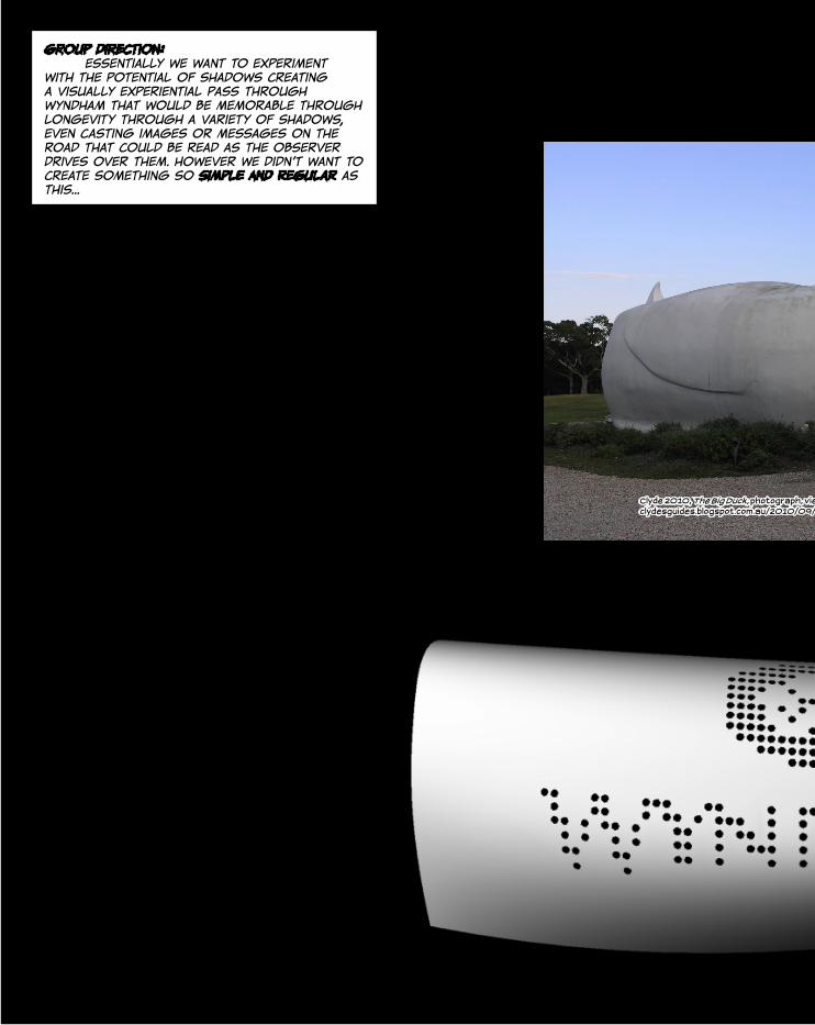
group direction: essentially we want to experiment with the potential of shadows creating a visually experiential pass through wyndham that would be memorable through longevity through a variety of shadows, even casting images or messages on the road that could be read as the observer drives over them. however we didn’t want to create something so simple and regular as this...
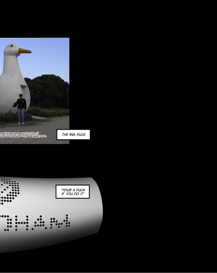
Clyde 2010, The Big Duck, photograph, viewed 20 September 2012, <http://clydesguides.blogspot.com.au/2010/09/big-duck-flanders-li-ny-stargazer.html>. the big duck
“your a duck if you do it”
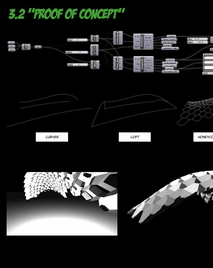
3.2 “proof of concept”
curves loft honeycomb overlay
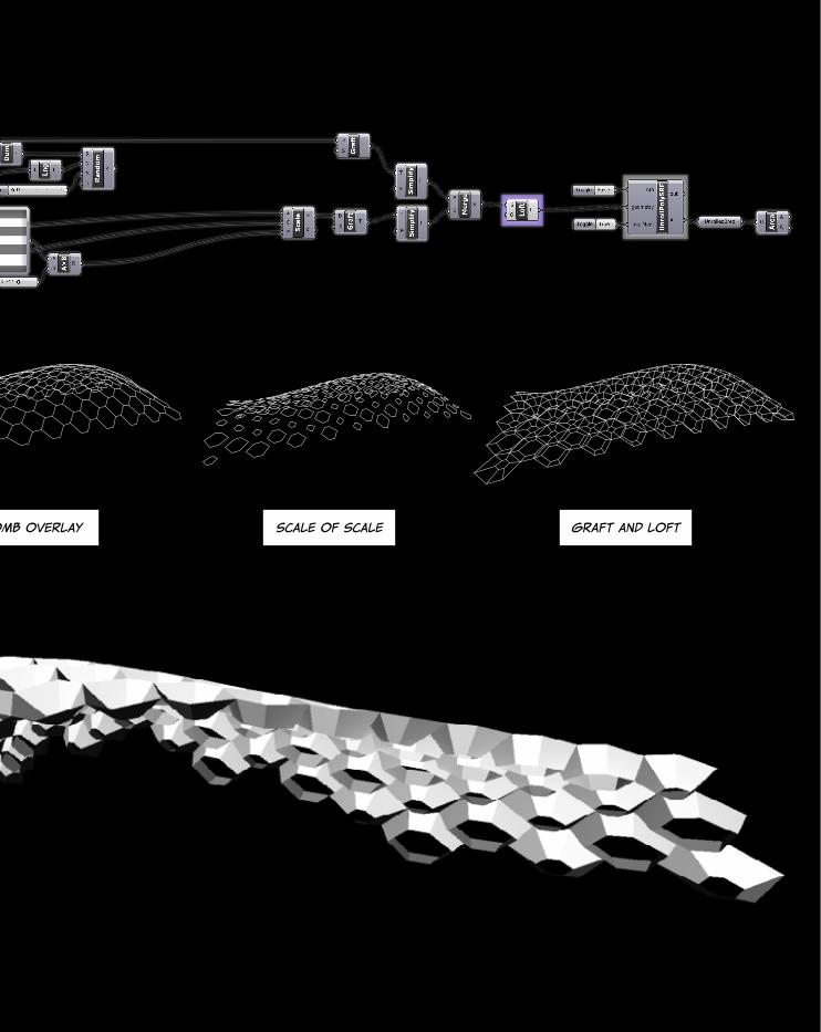
honeycomb overlay scale of scale graft and loft
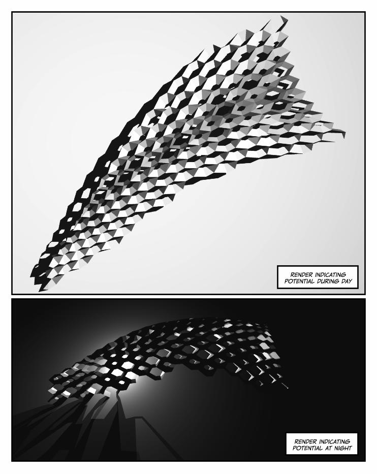
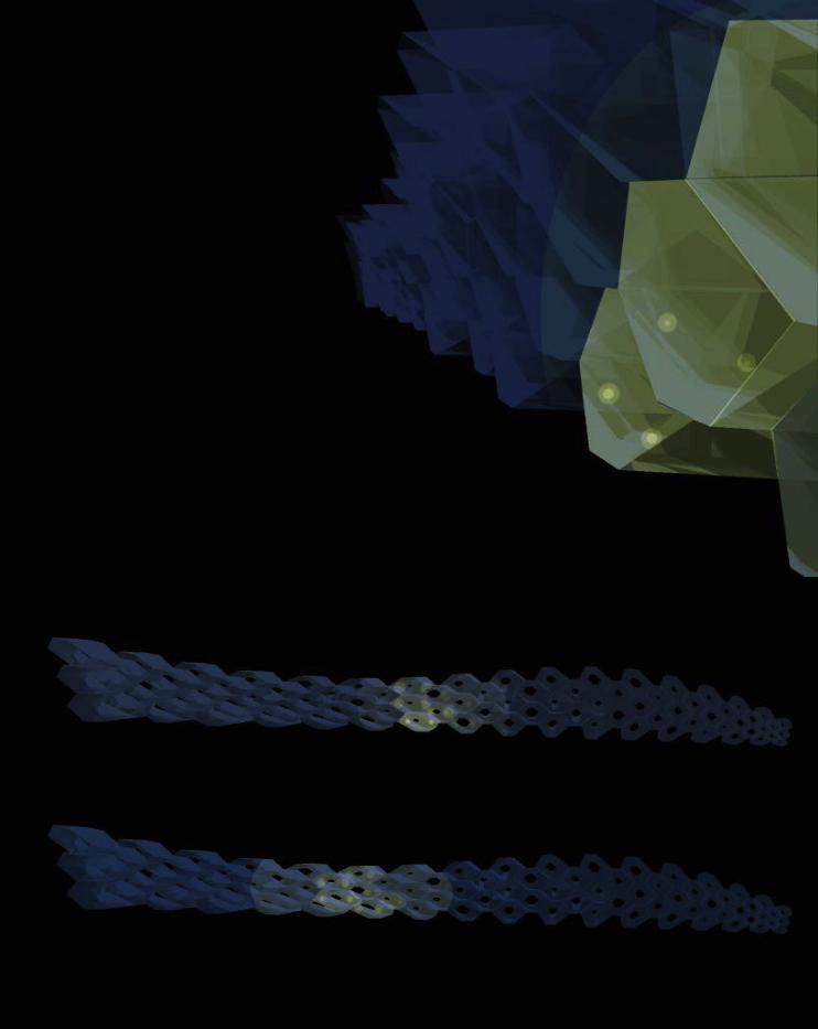
render indicating potential at night
render indicating potential during day
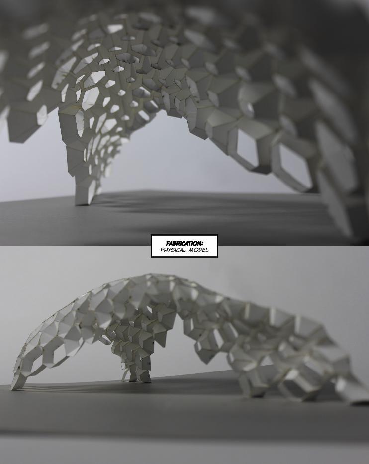
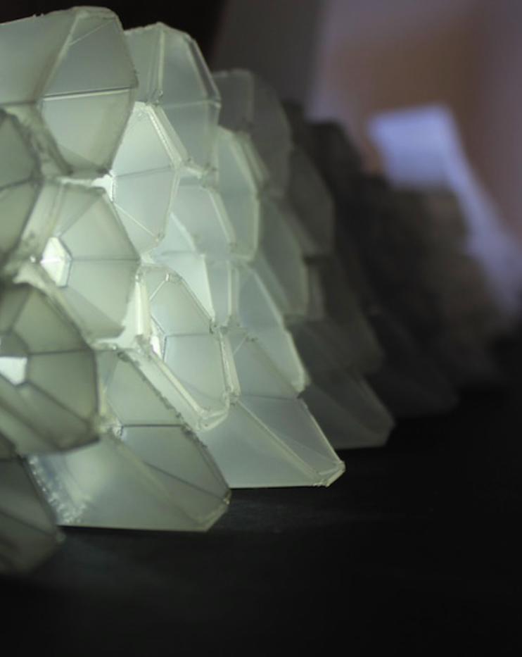
fabrication: physical model
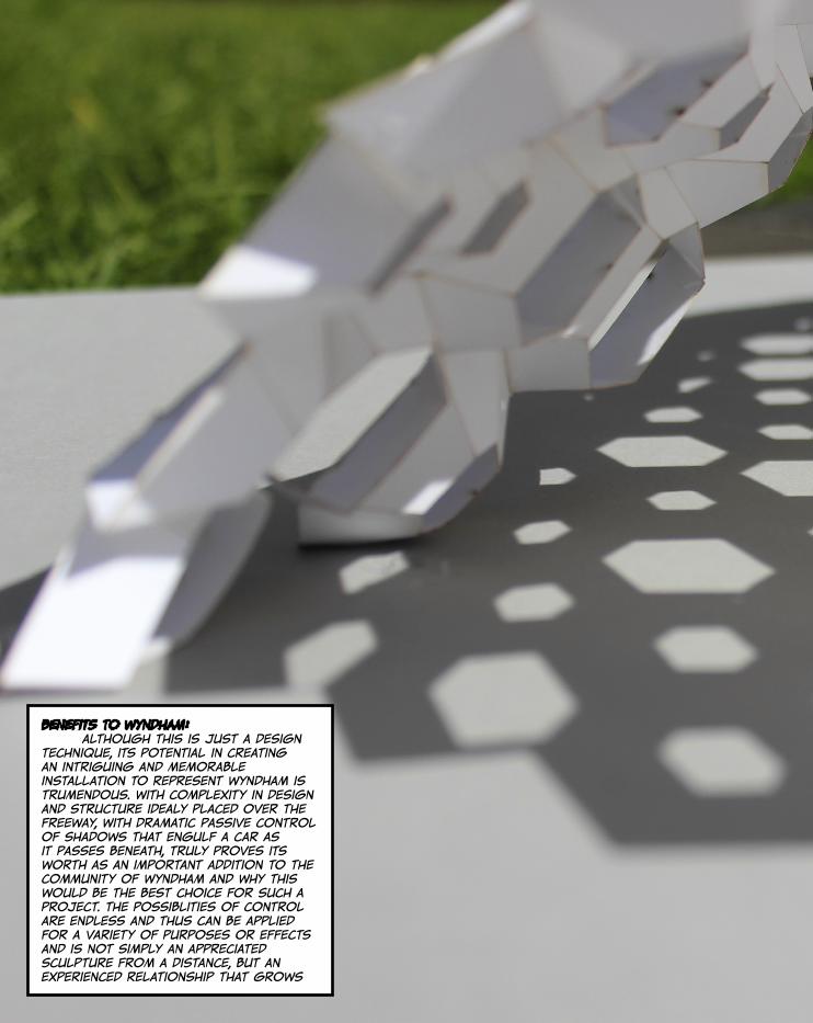
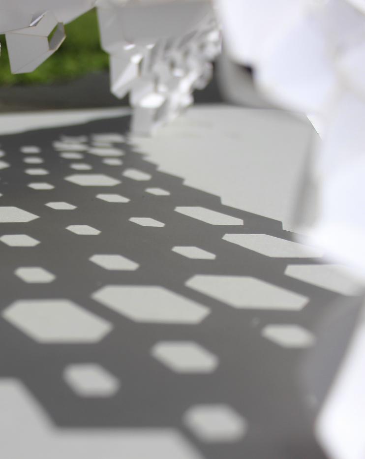
benefits to wyndham: although this is just a design technique, its potential in creating an intriguing and memorable installation to represent wyndham is trumendous. with complexity in design and structure idealy placed over the freeway, with dramatic passive control of shadows that engulf a car as it passes beneath, truly proves its worth as an important addition to the community of wyndham and why this would be the best choice for such a project. the possiblities of control are endless and thus can be applied for a variety of purposes or effects and is not simply an appreciated sculpture from a distance, but an experienced relationship that grows
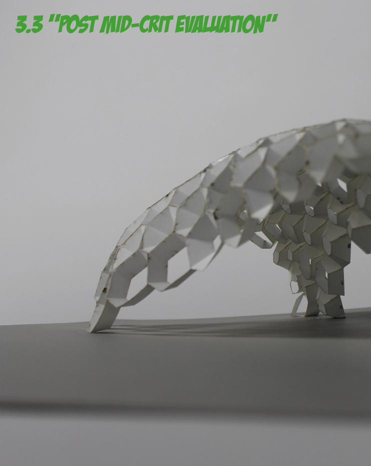
3.3 “post mid-crit evaluation”
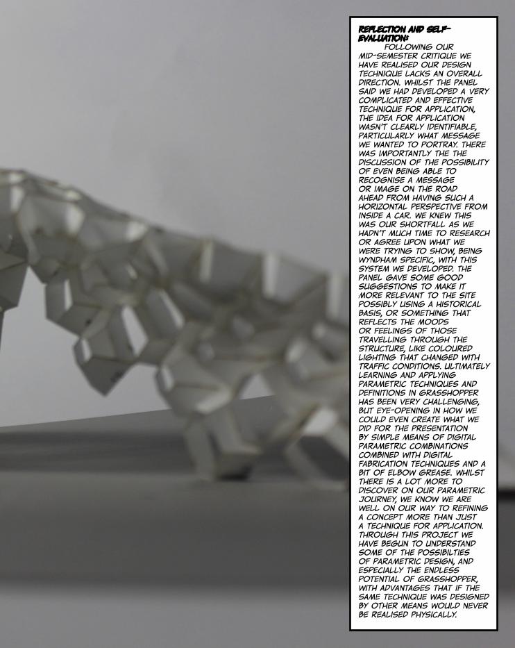
reflection and self-evaluation: Following our mid-semester critique we have realised our design technique lacks an overall direction. Whilst the panel said we had developed a very complicated and effective technique for application, the idea for application wasn’t clearly identifiable, particularly what message we wanted to portray. there was importantly the the discussion of the possibility of even being able to recognise a message or image on the road ahead from having such a horizontal perspective from inside a car. We knew this was our shortfall as we hadn’t much time to research or agree upon what we were trying to show, being wyndham specific, with this system we developed. The panel gave some good suggestions to make it more relevant to the site possibly using a historical basis, or something that reflects the moods or feelings of those travelling through the structure, like coloured lighting that changed with traffic conditions. Ultimately learning and applying parametric techniques and definitions in grasshopper has been very challenging, but eye-opening in how we could even create what we did for the presentation by simple means of digital parametric combinations combined with digital fabrication techniques and a bit of elbow grease. Whilst there is a lot more to discover on our parametric journey, we know we are well on our way to refining a concept more than just a technique for application. Through this project we have begun to understand some of the possibilties of parametric design, and especially the endless potential of Grasshopper, with advantages that if the same technique was designed by other means would never be realised physically.

4.0 gateway project
45
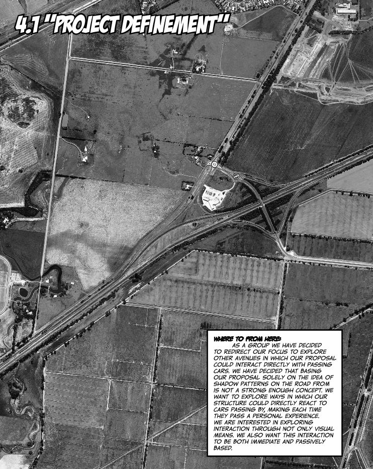
4.1 “project definement”
where to from here: as a group we have decided to redirect our focus to explore other avenues in which our proposal could interact directly with passing cars. We have decided that basing our proposal solely on the idea of shadow patterns on the road from is not a strong enough concept. We want to explore ways in which our structure could directly react to cars passing by, making each time they pass a personal experience. We are interested in exploring interaction through not only visual means. We also want this interaction to be both immediate and passively based.
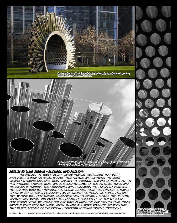
aeolus by luke jerram - acoustic wind pavilion: this project is essentially a large musical instrument that both amplifies the wind patterns, making them audible, and captures the light visually creating shadows which change throughout the day. It works as the wind vibrates strings which are attached to some of the 310 steel tubes and transfers it towards the structural arch, allowing the public to visualize the shifting wind map through the sound around them. This project looks at sound which we never considered as an interactive means. We could combine this method with our already developed skin to create a system that is both visually and audibly interactive to passing observers as we try to define our design intent. We could explore ways in which the car created wind could directly react with the installation, making it a more romantic relationship that is site specific of the freeway through wyndham traffic conditions.
Jerram, Luke 2011, Aeolus - Acoustic Wind Pavilion, lukejerram, viewed 10 October 2012, < http://www.lukejerram.com/aeolus>.
Spain, Andy 2011, Photo by Andy Spain, photograph, viewed 10 October 2012, <http://www.lukejerram.com/aeolus>.
Spain, Andy 2011, Harp Strings of the artwork, photograph, viewed 10 October 2012, <http://www.lukejerram.com/aeolus>.
Spain, Andy 2011, photograph, viewed 10 October 2012, <http://www.lukejerram.com/aeolus>.
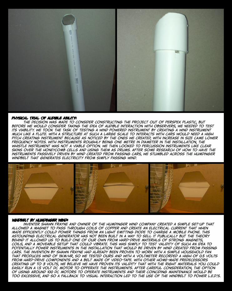
physical trial of audible ability: the decision was made to consider constructing the project out of perspex plastic, but before we would consider taking the idea of audible interaction with observers, we needed to test its viability. we took the task of testing a wind powered instrument by creating a wind instrument much like a flute. with a structure at such a large scale to interacts with cars would need a high pitch creating instrument because as noticed by the ones we created, with increase in size came lower frequency notes. with instruments roughly being one metre in diameter in the installation, the whistle instrument was not a viable option. we then looked to percussion instruments like clear skins over the honeycomb cells and using them as drums. after some research of how to have the instruments passively driven by wind created from passing cars, we stumbled across the humdinger windbelt that generates electricity from simply passing wind.
windbelt by humdinger wind: inventer shawn frayne and owner of the humdinger wind company created a simple set-up that allowed a magnet to pass through coils of copper and create an electrical current that when made efficiently could power things from an light emitting diode to charge a mobile phone. this astounding electrical generator has not been built in a way to sell it publically but the theory behind it allowed us to build one of our own from hard-drive materials of strong magnets, coils, and a moveable setup that could vibrate. this was simply to test validity of such an idea to potentially power instruments in the installation that would be driven by wind created from passing cars. the invention by shawn frayne had already been proven to work with a simple household fan that produces wind of 11km/hr, so we tested ours and with a voltmeter recorded a high of 0.5 volts from hard-drive components and a belt made of video-tape. with other home-made predecessors creating up to 3 volts, we believe we have proven its validity that with the right materials you could easily run a 1.5 volt DC motor to opperate the instruments. after careful consideration, the option of using around 100 DC motors to operate instruments and their coinciding maintenance would be too excessive, and so a fallback to visual interaction led to the use of the windbelt to power L.E.D.’s.

walk the line @ the v&a museum’s exhibition road tunnel by cinimod studio: this interactive lighting project gives precedance to the use of l.e.d. lighting and site specificity in a complex system that registers thermal movement and, with the lighting setup, follows pedestrains through the tunnel. as one enters the tunnel, the light band throws itself over the pedestrian and then follows them all the way to the other end until another pedestrian approaches. this was an overly successful design project for the london design festival 2012.
Cinimod Studio 2012, Walk The Light (at the V&A), cinimodstudio, viewed 10 October 2012, < http://cinimodstudio.com/project/walk-the-light-at-the-va>.
this has reassured our considerations of such a use of l.e.d. lighting in our own installation to visually and intrinsicly track the cars location behind a curtain wall as it disappears behind it and then re-emerges. the use of windbelts, that only vibrate and generate electricity as cars go past, would allow more than one car to be represented and tracked at any given time as the installation would light up at the point the car goes past and would then dim once the wind passes. the installation could take advantage of transparent perspex to achieve visual connection with the passing car themselves and those on the opposite side of the freeway. this also means that the parts the components of the windbelt could be contained with the cell as well as the lights to protect them from the external environment, and would be effective as the diffuse light within each cell would shine out and each cell illuminating in its own interaction with passing cars.
Cinimod Studio 2012, #image-05, photograph, viewed 10 October 2012, <http://cinimodstudio.com/project/walk-the-light-at-the-va>.
Cinimod Studio 2012, #image-08, photograph, viewed 10 October 2012, <http://cinimodstudio.com/project/walk-the-light-at-the-va>.
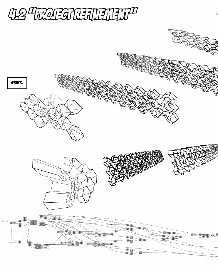
4.2 “project refinement”
start...
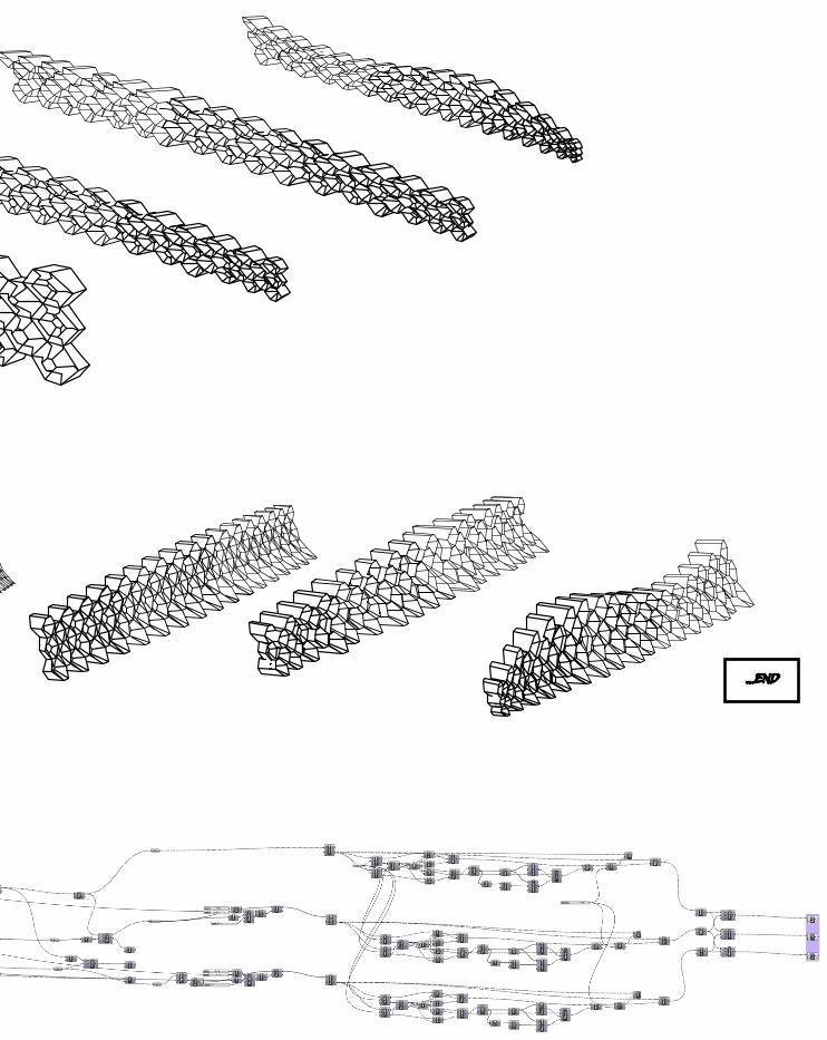
...end
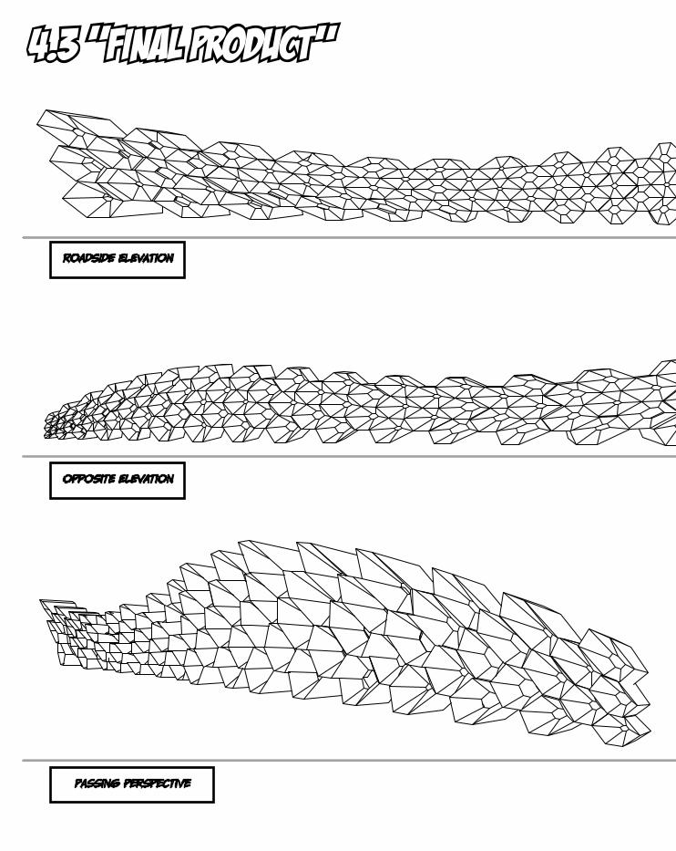
roadside elevation
opposite elevation
passing perspective
4.3 “final product”
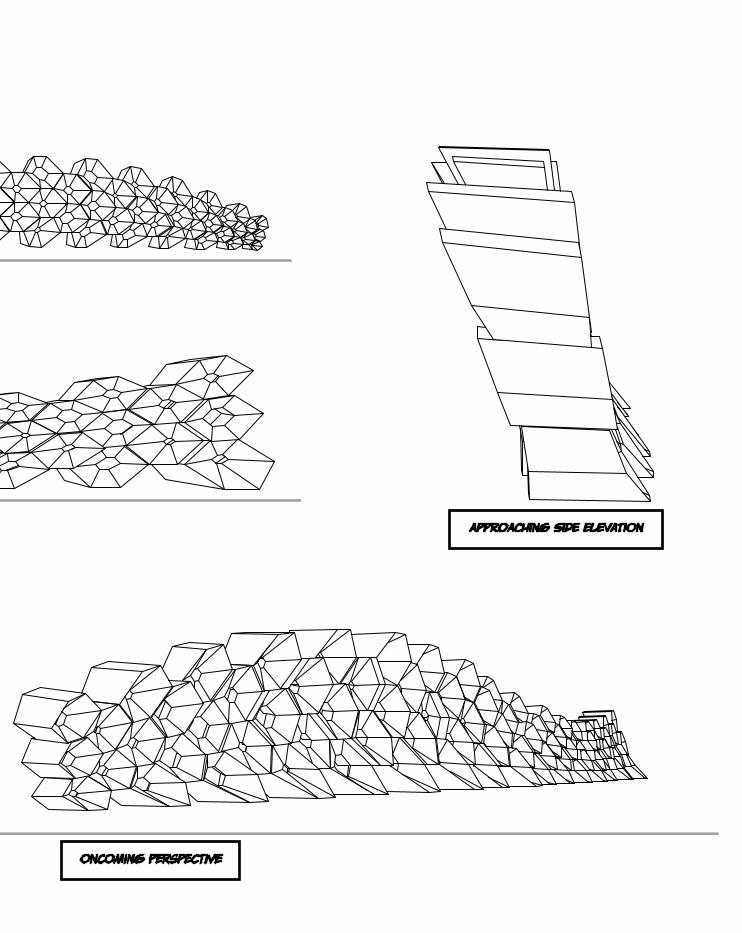
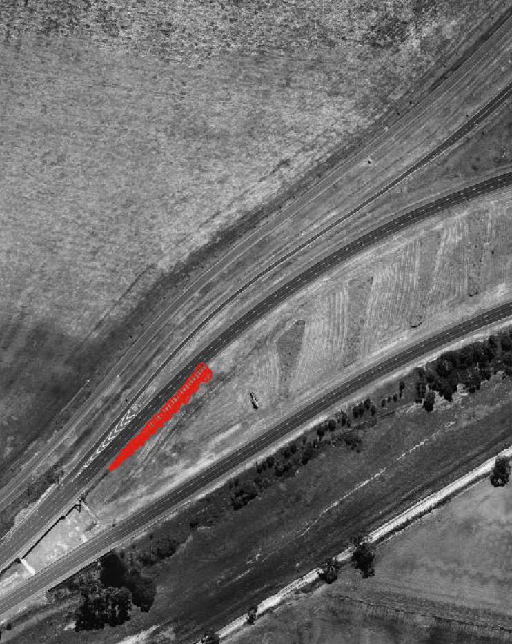
oncoming perspective
approaching side elevation
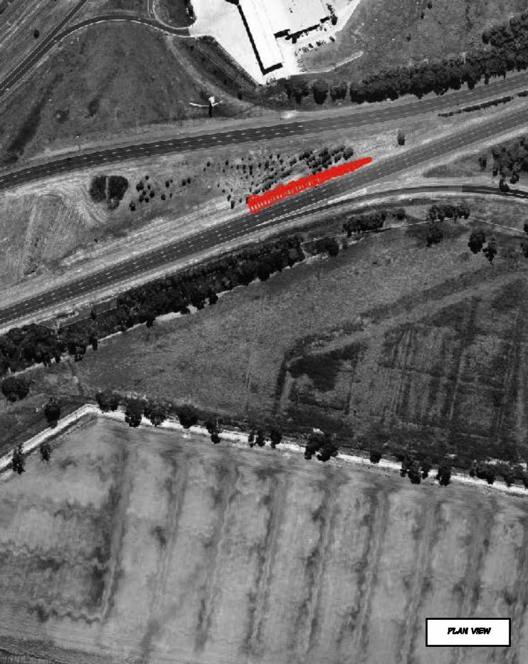
plan view
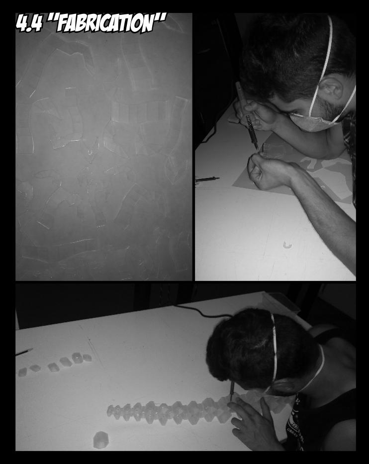
4.4 “fabrication”
refelction and self-assessment: From our final presentation we got some good, critical feedback for our proposal. essentially the panel had outlined that they thought we now had achieved a good design idea and system behind our proposal but some further work was needed to clear up some possible technical issues. They outlined some problems that we might face including issues ambient wind might cause despite encasement of the wind belt. They liked the fact that we had done a lot of our own research, but the construction of such a proposal wasn’t clearly defined or understood. there were improvements needed of proper site placement in physical model form and some better renders, but overall the design intent and proof of concept was extremely strong and highly encouraged, especially its passive site specific relationship. this semester has been exciting, interseting, and full-on, and for the first time in my architectural studies have i been pushed physically and mentally to use the latest technology to create something above and beyond my previous capabilities. the possibilities and potential of parametric design in its application and reformation of design ideals is phenominal and i only look to further my experience with these tools. special thanks to the coordination of a great subject by alison fairley, and to the tutors who pushed the parameters of my own abilities and thoughts, finnian warnock and hannes mcnamara.
4.5 “post final-crit evaluation”