Studio Air: Final Journal
111
SEMESTER 2 / 2014 THE UNIVERSITY OF MELBOURNE CINDY EDELENE ARIEF : 600604 TUTOR: B. D. ELIAS AIR STUDIO JOURNAL
-
Upload
cindy-edelene-arief -
Category
Documents
-
view
227 -
download
1
description
Â
Transcript of Studio Air: Final Journal
AIR | STUDIO JOURNAL 2
SEMESTER 2 / 2014THE UNIVERSITY OF MELBOURNE
CINDY EDELENE ARIEF: 600604TUTOR: B. D. ELIAS
AIRSTUDIO JOURNAL

1 AIR | STUDIO JOURNAL

table of contentsIntroduction
Part A: ConceptualisationA.1. Design Futuring Precedent Project 1: Kunsthaus Graz Precedent Project 2: Project ZEDA.2. Design Computation Precedent Project 1: Smithsonian Institution Precedent Project 2: 30 St Mary AxeA.3. Composition / Generation Precedent Project 1: Serpentine Pavilion Precedent Project 2: Port Authority Triple Bridge GatewayA.4. ConclusionA.5. Learning OutcomesA.6. Appendix - Algorithmic SketchesReferencesImage References
Part B: Criteria DesignB.1. Research FieldB.2. Case Study 1.0: Seroussi PavilionB.3. Case Study 2.0: ManifoldB.4. Technique: DevelopmentB.5. Technique: ProposalB.6. Learning Objectives and OutcomesB.7. Appendix - Algorithmic SketchesReferencesImage References
Part C: Detailed DesignC.1. Design ConceptC.2. Tectonic Elements and PrototypesC.3. Final Detail ModelC.4. Learning Objectives and OutcomesReferences
1
4571011131517192122232526
293337414553545555
607490102103
AIR
1 AIR | STUDIO JOURNAL
IntroductionMy name is Cindy Edelene Arief, currently sitting on my 3rd year undergraduate study majoring in architecture at the University of Melbourne.
Building my future dream house, is the basis of why I am pursuing a study in architecture. I have always been fascinated by the different feelings and emotions that emerge from being in a certain space, that is the product of architecture. I wish one day I can create the architectural space which gives people the same fascinated feeling and emotion as I have had.
I realised that in this era of technological development, architecture has somewhat shifted towards a more modern and digital approach.
Buildings seem to be more complex in form, shape, dimension as well as its construction process.
My relatively basic knowledge of digital design might not be sufficient enough to be able to build such complex designs.
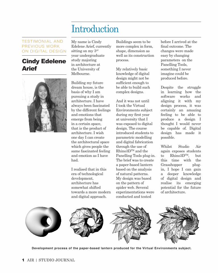
And it was not until I took the Virtual Environments subject during my first year at university that I was exposed to digital design. The course introduced students to parametric modelling and digital fabrication through the use of Rhino3DTM and the Panelling Tools plug-in. The brief was to create a paper-based lantern based on the analysis of natural patterns. My design was based on the pattern of spider web. Several experimentations were conducted and tested
before I arrived at the final outcome. The changes were made easy by changing parameters on the Panelling Tools, something I never imagine could be produced before.
Despite the struggle in learning how the software works and aligning it with my design process, it was certainly an amazing feeling to be able to produce a design I thought I would never be capable of. Digital design has made it possible.
Whilst Studio Air again exposes students to Rhino3DTM, but this time with the Grasshopper plug-in, I hope I can gain a deeper knowledge of digital design and realise its emerging potential for the future of architecture.
TESTIMONIAL AND PREVIOUS WORK ON DIGITAL DESIGN
Cindy Edelene Arief
Development process of the paper-based lantern produced for the Virtual Environments subject.

AIR | STUDIO JOURNAL 2
2 AIR | STUDIO JOURNAL
CONCEPTUALISATIONPART A
AIR | STUDIO JOURNAL 3
CONCEPTUALISATION
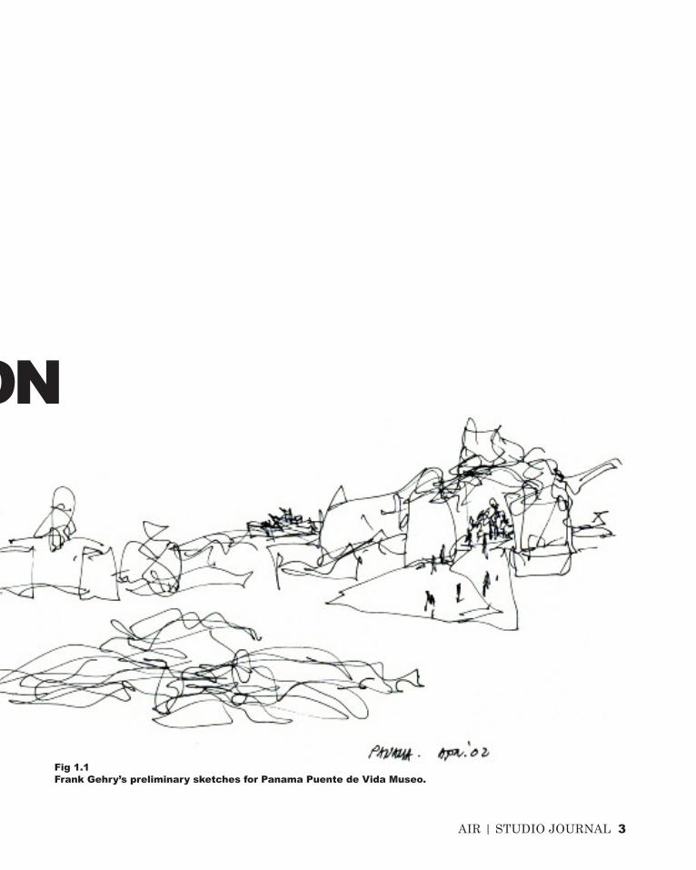
Fig 1.1Frank Gehry’s preliminary sketches for Panama Puente de Vida Museo.

4 AIR | STUDIO JOURNAL
‘Effectively, what we have done, as a result of the perspectival
limitations of our human centredness, is to treat the planet simply as an infinite resource at
our disposal.’
- Tony Fry1
DESIGN FUTURING
A.1

AIR | STUDIO JOURNAL 5
Twenty-first century humans are unquestionably aware of the environmental changes that have been largely, if not partially, caused by the destructive activities of theirselves. If these continue to occur over a long period of time, we might in the future look and turn back the time to possibly fix all our irresponsible actions towards the nature. Instead of regretting later, why don’t we start to make changes as early as we can? It all lies in what Fry indicates as ‘designing’. Humans all design. They have the capability to create things, whatever level of complexity, and to destroy things simultaneously.
Design Futuring - as its name indicates - leads to a basic implication of how one’s ability to design can have considerable impact and real difference for the future. It isn’t sustainability but rather “sustain-ability”, which is regularly emphasised by Fry, that needs to be acquired by every designer of all fields. Architecture as one of the practices too can serve as key drivers that can contribute in overcoming the problems possessed by defuturing.
It is because humans have all the power to choose what form of environment they long to create and live in that the act of design is substantially considered as the governing rule towards
the future and the effects it may have impact upon. This is why designers at the earliest stage must be aware, as much as they are aware of the ongoing drastic climate change, of the need to develop their design intelligence. In other words, understanding the whole complexity of designing: why they design what they want to design and what positive implications it may have brought towards the future, changing their way of thinking about design as a whole.
The following pages will discuss few examples on built projects that seek to capture the intelligence of designing towards a sustainable future.

6 AIR | STUDIO JOURNAL
In 2002, Peter Cook and Colin Fournier won the international competition for the Kunsthaus Graz in Austria, a multidisciplinary venue for contemporary exhibitions and events of art, media and photography. The building shows how the architects have merged the historical urban site with the new avant-garde design which serves a new architectural landmark for the city of Graz2.
The most interesting feature of Kunsthaus Graz is notably the blob-shape of the exterior
skin made up of 1,288 semi-transparent acrylic glass panels which generate energy through integrated photovoltaic panels3. Far more interestingly, its outer skin also acts as a media façade which can be changed electronically to cater the changing content of the museum. Visitors who enter the interior building can also feel the different spatial and sensorial experience as they walk through.
Though it may seem odd in shape, as what Frank Gehry did in his Guggenheim Museum
Fig 1.2 & 1.3Real-world & digital version of the blob-shaped glass panels.
KUNSTHAUS GRAZ,AUSTRIAPETER COOK & COLIN FOURNIER
PRECEDENT WORK 1

AIR | STUDIO JOURNAL 7
in Bilbao, Kunsthaus Graz is a clear example of how an iconic public building successfully regenerate the underprivileged image of the city through engagement with the public. This is something every architect needs to learn from, their design needs to speak to the community that it serves, and accordingly the community will respect the work that has been done.
The built-in photovoltaic units on the glazed panels makes the building not only have low environmental impact by generating its own power but also make easy the fabrication
process through paneling. The use of computer technology has aided the assembly process of the glass panel which make the fabrication more time-efficient. Moreover, glazing enables natural daylight to fill in the interior space thus saving energy and creating a more sustainable future.Kunsthaus Graz provides an efficient example that being intelligent in designing, both in terms of material selection and low energy emission, is crucial in slowing the rate of defuturing the world is currently undergoing. Architects play an important role in delivering a positive contribution towards a more sustainable future.
Fig 1.4An extremely modern
design sitting in the urban historic site of the city of
Graz.
8 AIR | STUDIO JOURNAL
Project ZED was part of a European-funded research project whose objective was to investigate the potential of achieving zero-carbon emission in a mixed urban development4.
In a highly-dense urban setting of London where most activities take place in indoor buildings, consuming considerable amount of energy along with the use of transportation, Future Systems sought to create a self-sufficient energy building to lower its environmental impact.
As the project’s title is “Project ZED: Towards Zero Emission Urban Development – The
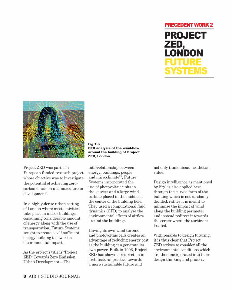
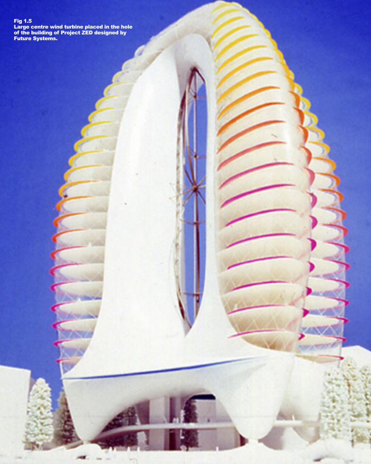
interrelationship between energy, buildings, people and microclimate”2, Future Systems incorporated the use of photovoltaic units in the louvers and a large wind turbine placed in the middle of the center of the building hole. They used a computational fluid dynamics (CFD) to analyse the environmental effects of airflow around the building5.
Having its own wind turbine and photovoltaic cells creates an advantage of reducing energy cost as the building can generate its own power. Built in 1996, Project ZED has shown a redirection in architectural practice towards a more sustainable future and
not only think about aesthetics value.
Design intelligence as mentioned by Fry1 is also applied here through the curved form of the building which is not randomly decided, rather it is meant to minimise the impact of wind along the building perimeter and instead redirect it towards the center where the turbine is located.
With regards to design futuring, it is thus clear that Project ZED strives to consider all the environmental conditions which are then incorporated into their design thinking and process.
Fig 1.6CFD analysis of the wind-flow around the building of Project ZED, London.
PROJECT ZED, LONDONFUTURE SYSTEMS
PRECEDENT WORK 2
AIR | STUDIO JOURNAL 2
Fig 1.5Large centre wind turbine placed in the hole of the building of Project ZED designed by Future Systems.
10 AIR | STUDIO JOURNAL
The term ‘computation’ and ‘computerisation’ are often mixed and misunderstood. They are in fact two distinctive features and understanding the difference is crucial in realising the importance of computation in architecture.
Computerisation refers to a mode of working where architects use computers to simply digitise certain procedures which have initially been conceived in the designer’s mind6. Computers are solely used for digital drafting, such as editing, copying and increasing drawings’ precisions.
On the other hand, computation involves processing of information through an understood model expressed as an algorithm and often it generates results that are unexpected, compared to the pre-conceptualised ideas that are digitised in the computerisation mode.
With the growing numbers of computer programs being
created, architects are increasingly allowed to explore new options and go beyond their capabilities. Computation does not only make it easier to adapt with changes that are often made throughout a design process, but it also lets the architects to predict its performance through the advanced tools they are using.
A more responsive and efficient design is enabled by computation, allowing the construction of complex models and giving performance feedback. Changing certain values of parameters within the digital tools can create multiple varieties of instances, most of which are complex geometries, which seem to be unachievable in the era where computer software had not yet existed.
The capability of experimenting with materials in computation also has a huge impact on the final outcome. It empowers the architects to create a performance-oriented design based on the evidence in the
environmental field, which leads them to an ecological design that responds to the environmental conditions.
Computation undoubtedly presents a huge potential in creating a more sustainable future through a more advanced and sophisticated design process. Architects are becoming equipped with the tools needed to overcoming solutions and even predict the project performance before executing.
Engaging with computational techniques is therefore essential and beneficial in relation to the sculptural form that is going to be generated throughout this course in response to the LAGI brief.
COMPUTATION VS COMPUTERISATION
DESIGN COMPUTATION
A.2

AIR | STUDIO JOURNAL 2
Fig 2.1Interior of the Smithsonian Institution Building showing the triangulated-surface roof canopy.

12 AIR | STUDIO JOURNAL
The analysis of two precedent works by Foster + Partners will show how engagement with contemporary computational techniques play a significant role in creating a sounder architecture. different professional fields is thus achieved. Accordingly, a design continuum is established between design and construction.7
The Smithsonian Institution in Washington DC, USA, shows how the use of a single computer program could
SMITHSONIAN INSTITUTION, WASHINGTON DCFOSTER + PARTNERS
PRECEDENT WORK 1

AIR | STUDIO JOURNAL 13
generate the geometry of such complex roof on its central courtyard.
Foster + Partners take into account the consideration of structural and acoustic performance which are incorporated into their design process.7 Through the use of computer code and collaboration with a Specialist Modeling Group (SMG), they explored many design options and did several modifications before reaching the final outcome. Computation thus enables Foster + Partners
to create a performance-based design with the inclusion of this environmental condition requirements into the parameter. It also shows that in computational design, designers are given the opportunity to explore and evaluate the best possible result.The use of digital modeling software in producing this roof canopy allows the architect as the master builder to communicate more efficiently with other professionals and trades involved in the production of buildings.
Engineers, for example, have a more comprehensive understanding in interpreting the architect’s design as the computer information is translated into the construction information.8
They are provided with guides in a language that builders can understand.
A better collaboration between different professional fields is thus achieved. Accordingly, a design continuum is established between design and construction.7
Fig 2.2 Computationally-generated roof geometry that allows natural daylight to enter the large interior space.

14 AIR | STUDIO JOURNAL
A similar approach to the use of computational design technique is again done by Foster + Partners in London, UK. The 30 St Mary Axe building is easily recognised through its tapering form towards the summit that sits on the city’s skyline (Fig 2.4).
It is not without reason, or simply the architects’ intention
to create the distinctive form of the building. Evidences, including environmental conditions and building performance requirements, are gathered. Each element of the building is the response of these constraints that have been incorporated in their design thinking.
As an internal specialist group, Foster + Partners consist
of computational designers working separately from the design teams. Designers are the ones dealing with the design process along with its varying needs depending on the project.
The building profile of 30 St Mary Axe is intended to reduce wind deflections compared to other rectilinear tower of similar size which helps maintain a comfortable environment at
30 ST MARY AXE, LONDONFOSTER + PARTNERS
PRECEDENT WORK 2

AIR | STUDIO JOURNAL 15
ground level as well as providing natural ventilation through the design of windows.9
These variables all affect the design process as a whole and digital linkage is established between the parametric modelers and the changing variables towards a performance-oriented design.Computation has signaled the point of significant innovation
in the 21st century, changing architectural practices in a way that only few were able to anticipate decades ago when production and construction of very complex forms used to be very difficult and unimaginable.8
Fig 2.4Identifiable building profile that tapers towards the summit in the background of the city’s skyline.
Fig 2.3The apex of the 30 St Mary Axe showing computational design technique.

16 AIR | STUDIO JOURNAL
In contemporary architecture, digital media is no longer seen as a representative tool for visualisation but as a generative tool for the derivation and transformation of forms.
Generative design is all about writing or scripting the rules which can be easily articulated to produce a range of possibilities from which the designers can further explore for development without knowing what the outcome is going to look like. It is not about “making of form” but rather “finding of form”.8
This generative design method involves a broad range of elements from algorithmic thinking, parametric modeling and scripting cultures. It has been discussed earlier that computation has played an extremely important role in solving complex architectural-related problems that were not achievable before the emergence of computer programs. By thinking algorithmically,
architects dealing with parametric modeling are to become familiarise with the culture of scripting, or writing all the differentiated rules, or variables which are to be incorporated into the design process.
The term parametric refers to the declaration of parameter rather than shape, the association in parts of a model with other elements. Through this associative relationship, multiple variations of creations are made possible by changing, or scripting, the value of the parameter.
The era of the new millennium has seen incredible approach towards parametric architecture, so much that the term ‘parametricism’ coined by Schumacher8 as the new style of architecture emerges.
There is ongoing debate whether parametricism can be proposed as a new style, however, it goes beyond the scope of the discussion
in this chapter. It is rather more essential to look at the potential of parametric approach to design that increasingly become part of architectural practices.
With parametric modeling, generation of forms, whatever level of complexity, is enabled through the ‘file-to-factory’ process of Computer Numerically Controlled (CNC) fabrication technologies. This allows engineers to construct complex forms more efficiently through the digital data that they receive and understand, something that was not achievable before the emergence of digital technologies. The development of new linkage between conception and production is therefore redefined.10
As scripting is enabled, a building performance can thus be predicted before construction takes place, allowing performance feedback to occur that results in a more efficient performance.
A SHIFT FROM COMPOSITION TO GENERATIVE DESIGN APPROACHCOMPOSITION/GENERATIONA.3

AIR | STUDIO JOURNAL 2
Fig 3.1Serpentine Pavilion (2002) by Toyo Ito demonstrating the aesthetic and tectonic possibilities of design computation.
18 AIR | STUDIO JOURNAL
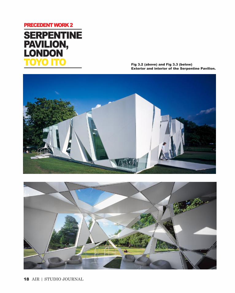
Fig 3.2 (above) and Fig 3.3 (below) Exterior and interior of the Serpentine Pavilion.
SERPENTINE PAVILION, LONDONTOYO ITO
PRECEDENT WORK 2
AIR | STUDIO JOURNAL 19
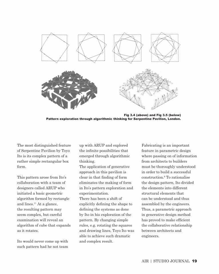
The most distinguished feature of Serpentine Pavilion by Toyo Ito is its complex pattern of a rather simple rectangular box form.
This pattern arose from Ito’s collaboration with a team of designers called ARUP who initiated a basic geometric algorithm formed by rectangle and lines.11 At a glance, the resulting pattern may seem complex, but careful examination will reveal an algorithm of cube that expands as it rotates.
Ito would never come up with such pattern had he not team
up with ARUP and explored the infinite possibilities that emerged through algorithmic thinking.The application of generative approach in this pavilion is clear in that finding of form eliminates the making of form in Ito’s pattern exploration and experimentation.There has been a shift of explicitly defining the shape to defining the systems as done by Ito in his exploration of the pattern. By changing simple rules, e.g. rotating the squares and drawing lines, Toyo Ito was able to achieve such dramatic and complex result.
Fabricating is an important feature in parametric design where passing on of information from architects to builders must be thoroughly understood in order to build a successful construction.8 To rationalise the design pattern, Ito divided the elements into different structural elements that can be understood and thus assembled by the engineers. Thus, a parametric approach in generative design method has proved to make efficient the collaborative relationship between architects and engineers.
Fig 3.4 (above) and Fig 3.5 (below) Pattern exploration through algorithmic thinking for Serpentine Pavilion, London.

20 AIR | STUDIO JOURNAL
Greg Lynn is widely known as an innovator in redefining the medium of design with digital technology. He is amongst one of the first architects to use animation software not as a medium of representation but rather of form generation.8
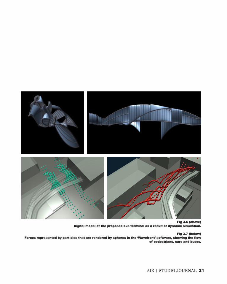
In his winning competition entry for the Port Authority Bus Terminal, Lynn used the ‘Wavefront’ software in representing series of ‘forces’ of traffic and pedestrian flow.12 He then exemplified these ‘forces’ by particles that were rendered in the software as spheres (Fig 3.7). These forces that originate not only from within the system itself but also from its surrounding context are essential in predicting, or simulating the object form that is being generated. It accounts for a perfomance feedback before the construction assembly is being executed, avoiding unexpected results that may arise.
Lynn’s design of a protective roof and lighting scheme for the bus terminal in New York serves
as an efficient example that making present the forces in a given context is fundamental in the form making of architecture. Mimicking natural phenomenon, in this case he used the movement and flow of pedestrians, cars and buses, Lynn then incorporated these into his design.
His use of parametric and generative design approach which are embedded in the dynamic simulation he created, has shown a major shift in the use of digital media as design tools rather than as devices for visual representation.
Generative design method further shows that applying natural principles into design does not necessarily mean copying from the nature. It involves learning from the nature and how we can produce, or more appropriately, generate form in response to the conditions of the environmetal context.
‘While physical form can be defined in terms of static coordinates, the virtual force of the environment in which it is designed contributes to its shape.’
PORT AUTHORITY TRIPLE BRIDGE GATEWAY, NEW YORKGREG LYNN
PRECEDENT WORK 2
- Greg Lynn cited in Kolaveric8
AIR | STUDIO JOURNAL 21
Fig 3.6 (above)Digital model of the proposed bus terminal as a result of dynamic simulation.
Fig 3.7 (below) Forces represented by particles that are rendered by spheres in the ‘Wavefront’ software, showing the flow
of pedestrians, cars and buses.

22 AIR | STUDIO JOURNAL
CONCLUSION
Architecture isn’t just a practice about creating space and building things. Many buildings which are aesthetically pleasing to human eyes may not be friendly to the environment. During the construction process, they may have consumed a lot of energy through the use of materials which are not renewable, a lot of money to transport the material from one place to another, as well as great amount of time in building the construction from the ground that varies depending on the level of complexity. Above all, it is the responsibility of future designers, including architects, to incorporate their design intelligence towards designing a more sustainable future, or slowing the rate of defuturing. Design intelligence ranges from wise material selection to responding to the local environmental conditions.
Unfortunately, tackling the problem of defuturing too often extends beyond what human’s capability can offer. This is why technology plays such an essential role. Contemporary built projects have shown that engagement with computing enables them to generate and build complex form which was thought to be unimaginable before the emergence of digital technology.
Computation has revolutionised
the way architectural practices behave in the 21st century. It allows designers to expand their abilities to deal with highly complex situation in response to design futuring.
In response to the brief of the LAGI project to create a public-art energy generator installation that is both environmentally and user friendly, my intended design approach will be to use materials that are highly renewable and locally-obtained as well as incorporating site conditions towards my design thinking. This will include consideration of sun path, wind flow, and other parameters that should be integrated within the generation of form assisted by digital computer software, in this case, Rhino3DTM and Grasshopper.
By doing so, not only will the designers be benefited as computation enables complex problem to be solved in a timely manner, but also the engineers dealing with the construction process who are guided with ‘construction language’ translated from the digital they are able to understand. It will also consume less time and cost to build as local materials do not require to be transported from a far, and the local people in Copenhagen will appreciate it more when seeing local resources being used.
AIR | STUDIO JOURNAL 23
LEARNING OUTCOMES
My understanding about architectural design has broadened so much after learning about the theory and practice of architectural computing.
Previously, I was not aware that computation has played such an important role in contemporary architectural practice. I was wondering how builders are able to construct such complex form of buildings. This all has been made possible by the use of digital technology that enables fabrication process to take place relatively easily.Through Grasshopper, I now understand that changing basic and simple rule or parameter can result in multiple variation of creations and even lead to very complex forms, forms that I
thought I am not able to generate. Although it may seem daunting at the beginning to learn how to use Grasshopper without any preliminary background, I began to see the potential of computation for my future design career.
I have always designed things that are aesthetically pleasing, not considering any environmental conditions or situations that need to be taken into consideration, even if so, at a very limited level as no concrete approach can be taken at that point. Now that digital computation has aided in this problem, I am very much looking forward to what outcome I can possibly achieve with the assistance of computation, specifically for the design for the energy generator installation.

24 AIR | STUDIO JOURNAL
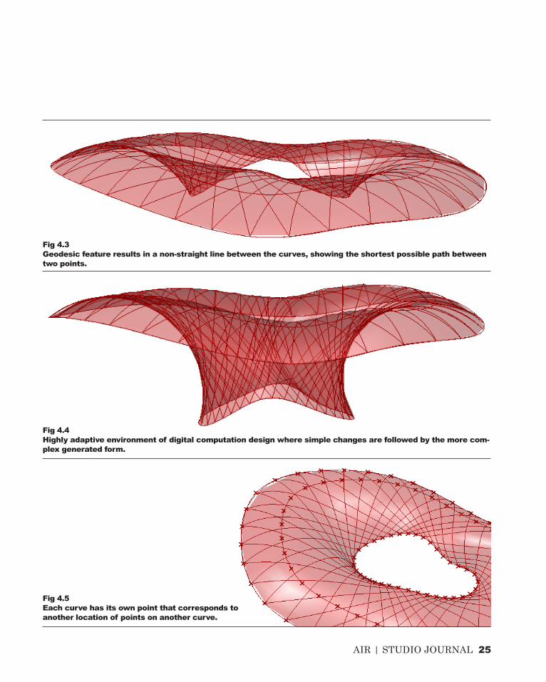
From creating arches between two curves (see Fig 4.1 ), I began to see the potential of generating a much more complex form. It turned out that a form as shown on the next page was generated, though some rules needed to be changed as they consist of 3 different curves whose points need to be shifted in order to produce the grid shell surface.
Whilst watching the video tutorial, I discovered the use of geodesic feature which is to create shortest possible path between two points. This instantly reminds me of the design futuring approach, in which I can apply the capability of this feature in Grasshopper through minimising the use
of materials that I intend to use for the energy generator installation.
I believe that there are still more features that I will discover throughout my learning process of Grasshopper in this course which can assist me in generating my design form.Another very important lesson that I learn is, as mentioned earlier, computation allows complex form to be generated in a very short time. This is shown by how changing the control points of the curve in Fig 4.4 can result in an unexpected outcome where association between its elements enable the responsive adaptation to the changing parameter.
Fig 4.1Arches created between two curves.
Fig 4.2Grasshopper script for the grid shell form shown on the next page.
ALGORITHMIC SKETCHES
AIR | STUDIO JOURNAL 25
Fig 4.4Highly adaptive environment of digital computation design where simple changes are followed by the more com-plex generated form.
Fig 4.5Each curve has its own point that corresponds to another location of points on another curve.
Fig 4.3Geodesic feature results in a non-straight line between the curves, showing the shortest possible path between two points.

26 AIR | STUDIO JOURNAL
1 Fry, Tony (2008). Design Futuring: Sustainability, Ethics and New Practice (Oxford: Berg), pp. 1.
2 Universalmuseum Joanneum, 2014, ‘Kunsthaus Graz’, <http://www.museum-joanneum.at/en/kunst-haus-graz/architecture.html> [Accessed: 8 August 2014].
3 Ana Lisa, 2014, ‘Austria’s Blob-Shaped Kunsthaus Graz Art Museum Generates its Own Solar Power’, <http://inhabitat.com/austrias-blob-shaped-kunsthaus-graz-art-museum-generates-its-own-solar-pow-er/> [Accessed: 8 August 2014].
4 Steemers, K. and Nikolopoulou, M. (1998). “Assessing the Urban Microclimate: Introducing Innovative Modelling Techniques.” PLEA 98 Passive and Low Energy Architecture Conference (1998).
5 Kolarevic, Branko. “Computing the performative in architecture.” Proceedings of the 21th eCAADe Con-ference: Digital Design. Graz, Austria. 2003.
6 Peters, Brady. (2013) ‘Computation Works: The Building of Algorithmic Thought’, Architectural Design, 83, 2, pp. 8-15.
7 Foster + Partners 2014, “Smithsonian Institution” in Foster + Partners Ltd < http://www.fosterandpart-ners.com/projects/smithsonian-institution/> [Accesssed 17 August 2014].
8 Kolarevic, Branko, Architecture in the Digital Age: Design and Manufacturing (New York; London: Spon Press, 2003), pp. 3-62.
9 Foster + Partners 2014, “30 Sty Mary Axe” in Foster + Partners Ltd <http://www.fosterandpartners.com/projects/30-st-mary-axe> [Accessed 17 August 2014].
10 Oxman, Rivka and Robert Oxman, eds (2014). Theories of the Digital in Architecture (London; New York: Routledge), pp. 1–10.
11 Deuling, Ton, “Serpentine Pavilion // Case Study” in Collective Architects <http://www.collectivearchi-tects.eu/blog/77/serpentine-pavilion-case-study> [Accessed 19 August 2014].
12 Gregg Lynn FORM 2014, “Port Authority Triple Bridge Gateway” in Gregg Lynn FORM <http://gl-form.com/buildings/port-authority-triple-bridge-gateway-competition/> [Accessed 20 August 2014].
References

AIR | STUDIO JOURNAL 27
Fig. 1.1Frank Gehry, “Preliminary sketches for the Panama Puente de Vida Museo” in Gehry Partners, LLP, <http://www.foga.com/> [Accessed 18 August 2014]
Fig 1.2Ana Lisa, 2014, ‘Austria’s Blob-Shaped Kunsthaus Graz Art Museum Generates its Own Solar Power’, <http://inhabitat.com/austrias-blob-shaped-kunsthaus-graz-art-museum-generates-its-own-solar-pow-er/> [Accessed: 8 August 2014].
Fig 1.3Universalmuseum Joanneum, 2014, ‘Kunsthaus Graz’, <http://www.museum-joanneum.at/en/kunsthaus-graz/architecture.html> [Accessed: 8 August 2014].
Fig 1.4Ana Lisa, 2014, ‘Austria’s Blob-Shaped Kunsthaus Graz Art Museum Generates its Own Solar Power’, <http://inhabitat.com/austrias-blob-shaped-kunsthaus-graz-art-museum-generates-its-own-solar-pow-er/> [Accessed: 8 August 2014].
Fig 1.5, 1.6Techniker, “Project ZED”, Techniker Ltd <http://www.techniker.co.uk/projects/detail.cfm?iProject_id=121> [Accessed 9 August 2014]
Fig 2.1, 2.2Foster + Partners 2014, “Smithsonian Institution” in Foster + Partners Ltd <http://www.fosterandpartners.com/projects/smithsonian-institution/> [Accesssed 17 August 2014]
Fig 2.3, 2.4Foster + Partners 2014, “Smithsonian Institution” in Foster + Partners Ltd <http://www.fosterandpartners.com/projects/30-st-mary-axe> [Accesssed 17 August 2014]
Fig 3.1Balmond Studio Photographer, “Serpentine Pavillion 2002” in Archello < http://www.archello.com/en/project/serpentine-pavilion-2002#> [Accessed 19 August 2014].
Fig 3.2, 3.3Sylvain Deleu, “Serpentine Gallery Pavilion 2002 / Toyo Ito + Cecil Balmond + Arup” in ArchDaily <http://www.archdaily.com/344319/serpentine-gallery-pavilion-2002-toyo-ito-cecil-balmond-arup/> [Acessed 19 August 2014].
Fig 3.4, 3.5Deuling, Ton, “Serpentine Pavilion // Case Study” in Collective Architects <http://www.collectivearchi-tects.eu/blog/77/serpentine-pavilion-case-study> [Accessed 19 August 2014]
Fig 3.6, 3.7Gregg Lynn FORM 2014, “Port Authority Triple Bridge Gateway” in Gregg Lynn FORM <http://glform.com/buildings/port-authority-triple-bridge-gateway-competition/> [Accessed 20 August 2014].
Image References
1 AIR | STUDIO JOURNAL
CRITERIA DESIGNPART B

AIR | STUDIO JOURNAL 2
CRITERIA DESIGN

30 AIR | STUDIO JOURNAL
Buildings are made up of different parts and materials which are assembled according to the specified technique.13
Some of the digital fabrication techniques that have emerged within contemporary architectural practice are patterning, tesselation, folding, sectioning, geometry, structure, biomimicry and structural performance.
As a starting point to develop technique for the design of LAGI competition project, the focus is narrowed down into a single material system, in this case folding, which will then begin to look at some of precedent projects involving that technique.
Folding is one of the material techniques in architectural design where a flat surface is turned into a three-dimensional one.13 Through folding, materials being used can gain stiffness and rigidity, span some distances and support themselves, just as what a traditional Japanese origami paper craft works (Fig 5.1). Folding has been widely used in architectural fields because it is materially economical, visually appealing and effective at multiple scales.13
Digital tools have enabled folding technique to generate complex forms in a way that human capability of folding cannot create. In the fabrication
Fig 5.1 (above)Folding in traditional origami instructions.Fig 5.2 (below)Office dA, Fabricating Coincidences, Museum of Modern Art, New York, 1998.Fig 5.3 (right)Dragonly installation by Tom Wiscombe/EMERGENT, 2007.
RESEARCH FIELD
B.1
MATERIAL SYSTEM // FOLDING

AIR | STUDIO JOURNAL 31
process, the three-dimensional structure is unrolled or unfolded into two-dimensional templates through digital softwares such as Rhinoceros and Grasshopper, making it easier and more feasible to build. The process is further eased by the use of digital machines such as laser cut, water-jet or plasma cutters to produce the fabricated folded surfaces.
Despite its structural stiffness, however, folding also has some disadvantages. Folding technique is very much restricted to the material selection as its effectiveness depends on the elastic and plastic properties of the
material.13 For example, the seam detail of the Office dA’s installation of Fabricating Coincidences needs to be redesigned as manufacturing process limits the initial design concept.13 Thus, there needs to be a close association between materials selection and fabrication process in folding.In fact, more than one material system/technique is often applied into a single architectural project.
The installation of Dragonfly employs the technique of both folding and biomimicry, in which its honeycomb patterns provide the basis of the more complex and dynamic curvature pattern and in which
folding is used for its structural performance through spanning of the depth of the band. Similarly, Seroussi Pavilion adopts folding and biomimicry, a case study that is to be explored on for the iteration process in the next chapter.
Fig 5.4Biothing, Seroussi Pavilion, Paris, 2007.

32 AIR | STUDIO JOURNAL
Seroussi Pavilion serves a great example of how computational design enables the generation of such complex form. Designed by Alisa Andrasek, this case study is chosen because it proves to adapt many features on the site that can be applied and manipulated in the script, which could as well be adopted in responds to the LAGI brief.
“Through logics of attraction/repulsion, trajectories were computed in plan and than lifted via series of structural microarching sections through different frequencies of sine function.”14 Its rather unique growing pattern is based on the behaviour of electromagnetic field that is embedded within the algorithmic and parametric design thinking. Another example of direct application within the context that is applied as the parameter is the distribution of lighting/shading across the pavilion that relies on the sine-wave function which controls the parametric differentiation of angle and size.14
Drawing from the fact of environmental application and consideration within the design process, this case study thus ties in with the aim of adopting computational design tool that does not leave behind the issue of defuturing as described in the previous part.
SEROUSSI PAVILIONBIOTHING/ALISA ANDRASEK
CASE STUDY 1
AIR | STUDIO JOURNAL 2

34 AIR | STUDIO JOURNAL

AIR | STUDIO JOURNAL 35
Pushing the definitions further and manipulating the values of certain parameters have enabled the creation of multiple iterations which differ greatly, if not to some extent, from its original form. Some of the parameters that have been changed to produce these iterations are:- number of segments in dividing the curves- field spin (its strength, radius, decay)- field line- graph mapper
CASE STUDY 1B.2ITERATIONS // SEROUSSI PAVILION

36 AIR | STUDIO JOURNAL
1 2
3 4
Selected Iterations & Selection Criteria

AIR | STUDIO JOURNAL 37
The most intriguing characteristic of this iteration is the radial path that is produced and grows out of the centre, or similarly, converges into the centre. This approach is similar to the first iteration, where variety of access points allow greater opportunity to explore.
The first selected iteration shows the potential of how the surroundings of the design site can be attracted onto one single point at the centre. This could lead to the path where visitors are going to approach the site, coming from different parts of the site but gather at one point, which is the art installation itself. The curves also represent a sense of attraction and repulsion that draws people in and out of the site.
First IterationExploration of field lines enable the production of this iteration. It is chosen on the basis of how several gathering points, represented by the inner circle, could be created within the site and produce different outcome on the overall form.
Second Iteration
Third IterationThe tunnel-like structure of this three-dimensional iteration can have the potential of stimulating and challenging the mind of visitors where they have the freedom to explore each of the strip that connects to one another.
Fourth Iteration

38 AIR | STUDIO JOURNAL
The Manifold installation is part of a research project done by Andrew Kudless for the MA dissertation in Emergent Technologies and Design at the Architectural Association, London, UK. The project aims at the development of material systems that has a high integration between peformance and design.15 As discussed earlier, the application of material systems in an architectural project is often mixed and overlapped. In this case, Manifold employs the biomimetic approach of the honeycomb pattern alongside the folding system. Departing from pure hexagonal geometry, Andrew Kudless developed a RhinoScript to create the skewed hexagonal pattern that is based on alignments and deviations of the front and back walls of the two surfaces.15 The relationship of this cellular configuration to its overall form seems rather successful in that it maintains structural integrity that takes into account the visual and material considerations. This project is thus chosen for the reverse engineering in that it contains the folding approach that is to be developed further.
Fig 5.5Installation process of Manifold by Andrew Kudless.
CASE STUDY 2B.3PROJECT INTRODUCTION

AIR | STUDIO JOURNAL 2
MATSYS/ ANDREW KUDLESSMANIFOLD

40 AIR | STUDIO JOURNAL
1
1
1
5
12
Create multiple curves.
Loft the hexagonal structure lines created earlier using lunchbox.
Using loft command, create a surface from the curves created.
Reverse Engineering

AIR | STUDIO JOURNAL 41
13 14
From plaster-form finding model, prototype detail, fabrication detail to the detail of reverse engineering
Offset the surface for some distance. Create hexagonal structure on each of the surface using the lunchbox plug-in
on Grasshopper. Maintain the same U & V parameter value for each.
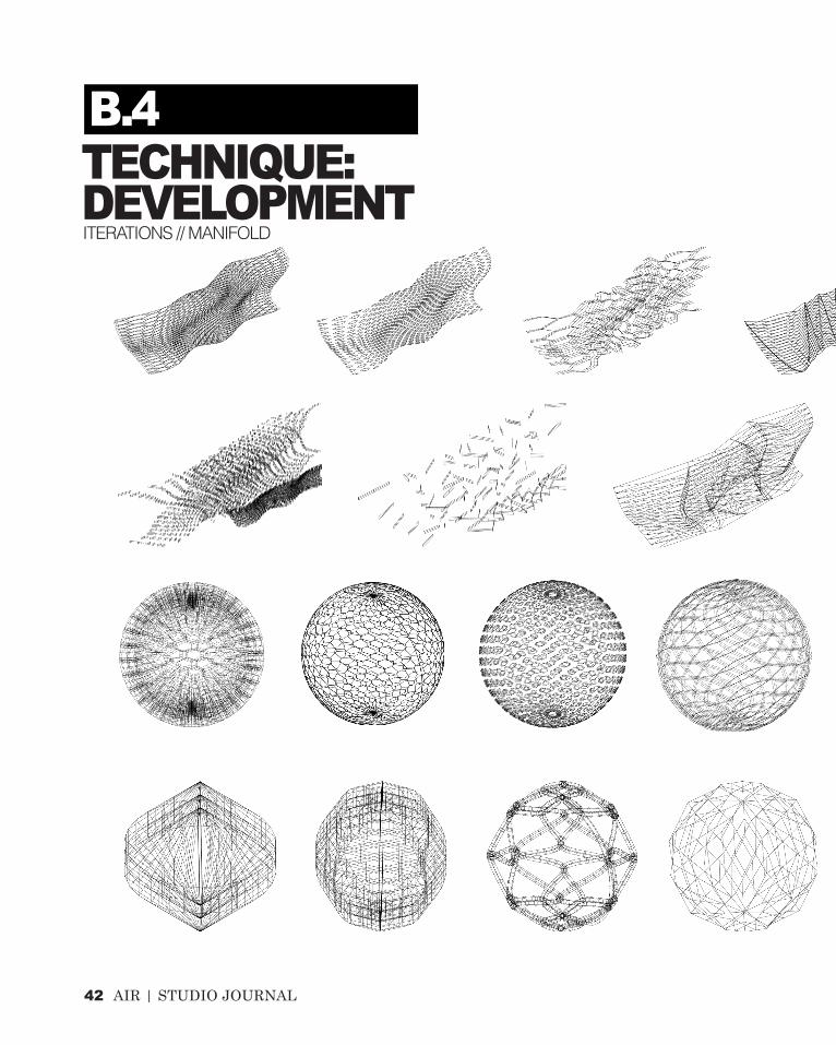
42 AIR | STUDIO JOURNAL
TECHNIQUE:DEVELOPMENT
B.4
ITERATIONS // MANIFOLD

AIR | STUDIO JOURNAL 43

44 AIR | STUDIO JOURNAL
2
43
1
Selected Iterations & Selection Criteria
AIR | STUDIO JOURNAL 45
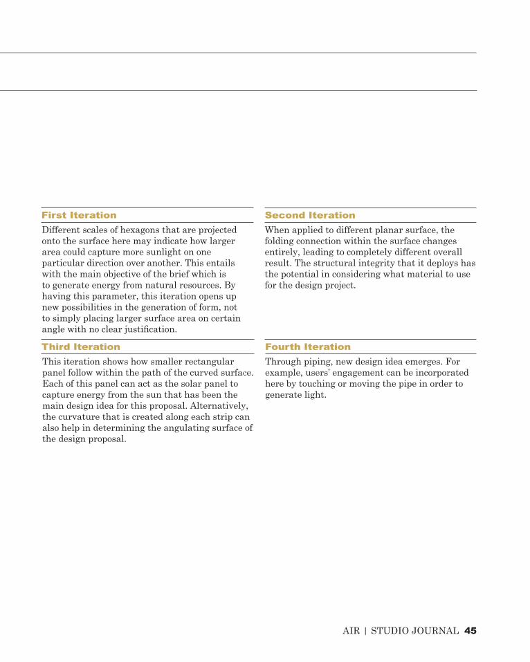
This iteration shows how smaller rectangular panel follow within the path of the curved surface. Each of this panel can act as the solar panel to capture energy from the sun that has been the main design idea for this proposal. Alternatively, the curvature that is created along each strip can also help in determining the angulating surface of the design proposal.
Different scales of hexagons that are projected onto the surface here may indicate how larger area could capture more sunlight on one particular direction over another. This entails with the main objective of the brief which is to generate energy from natural resources. By having this parameter, this iteration opens up new possibilities in the generation of form, not to simply placing larger surface area on certain angle with no clear justification.
First IterationWhen applied to different planar surface, the folding connection within the surface changes entirely, leading to completely different overall result. The structural integrity that it deploys has the potential in considering what material to use for the design project.
Second Iteration
Third IterationThrough piping, new design idea emerges. For example, users’ engagement can be incorporated here by touching or moving the pipe in order to generate light.
Fourth Iteration

46 AIR | STUDIO JOURNAL
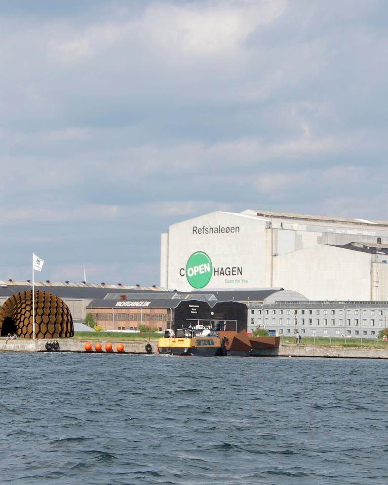
Refshaleøen, Denmark
View across the Harbour
Sunlight ExposureAccess Points Surrounding Landmarks
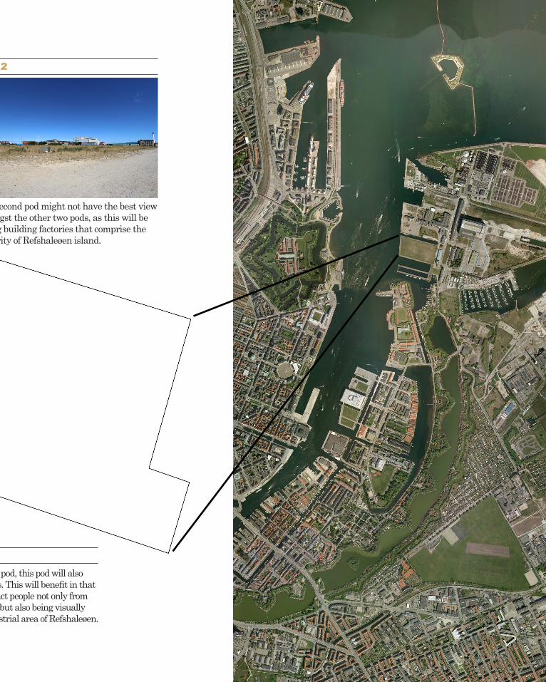
The diagrams above show that the design site is located in a separate island from the city centre, where it used to be a former industrial site. Having a rather limited access points and being quite distant from the city, my design proposal seeks to capture the interests amongst
people across the harbour, in particular visitors of the iconic statue of Copenhagen, Little Mermaid, that has direct view to the design site. The proposal also seeks to make the most of the sunlight exposure in which solar energy is to be generated.
TECHNIQUE:PROPOSAL
B.5
SITE ANALYSIS
AIR | STUDIO JOURNAL 47
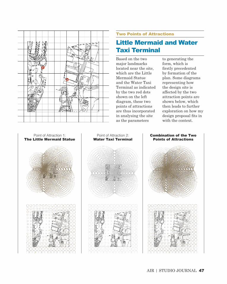
Based on the two major landmarks located near the site, which are the Little Mermaid Statue and the Water Taxi Terminal as indicated by the two red dots shown on the left diagram, these two points of attractions are thus incorporated in analysing the site as the parameters
to generating the form, which is firstly precedented by formation of the plan. Some diagrams representing how the design site is affected by the two attraction points are shown below, which then leads to further exploration on how my design proposal fits in with the context.
Point of Attraction 1:The Little Mermaid Statue
Point of Attraction 2:Water Taxi Terminal
Combination of the Two Points of Attractions
Two Points of Attractions
Little Mermaid and Water Taxi Terminal

48 AIR | STUDIO JOURNAL
Iteration from Case Study 1Seroussi Pavilion
Iteration from Case Study 2Manifold
1. Standing Platform2. Human interaction: Pressure3. Real-time immediate effect: LED Panel
Form Generation for Design Proposal
+ =
The proposal largely relies on participation of audiences as they stand on the grounding platform of the installation, giving pressure and thus stimulating the LED panel to generate lights on its outer skin. The solar energy that is captured during the day is used in order to make this lighting installation function. This public art installation is meant not to just stand on its own, but rather to become part of the experience of the participant.
TECHNIQUE:PROPOSAL
B.5
DESIGN PROCESS
Design Proposal
TECHNIQUE:PROPOSAL
B.5

AIR | STUDIO JOURNAL 49
This precedent project of lighting installation serves as a great example of how users’ participation becomes an integral part of the way the project functions. LiquiFloor is a unique flooring system made of transparent vinyl tiles that contain coloured liquid which can flow and swirl as people step on it.16 It thus creates unlimited variations as different gestures produce different outcomes on the floor. It was first originated by Cafe Interior for a nightclub in Los Angeles before it was further sought out by many interior designers and architects throughout the country for different applications such as restaurants, bars, museums, schools and hospitals. This idea inspires my lighting installation proposal where active participation of users can create an intriguing effect, constantly changing their perceived experience in a given space.
LIQUIFLOOR, LOS ANGELESCAFE INTERIOR
PRECEDENT WORK

50 AIR | STUDIO JOURNAL
Jointing and Structural Detailing of the Hexagon Skin Surface of the City Lights Pavilion
TECHNIQUE:PROPOSAL
B.5
JOINTING // STRUCTURAL DETAILING
TECHNIQUE:PROPOSAL
B.5

AIR | STUDIO JOURNAL 51
As no prototype was required in this part, some thoughts on structural detailing and jointing are worth considering in making sure that the proposal can actually work structurally. The hexagon panels that are applied onto the skin are made up of timber beams which are then connected and bolted using galvanised L-shaped steel plate. It is important to use material that can be obtained locally because
it will contribute less to the embodied energy, including the transport and production costs that could otherwise be reduced by having the material produced locally. An advantage of using galvanised steel plate and bolt is that they have tough coating which ensures that they have longer life period, especially to cope with the high coastal exposure of the design site at Refshaleøen.
Timber Beam
Galvanised L-shaped Steel Plate
Galvanised Steel Bolt

1 AIR | STUDIO JOURNAL
CITY LIGHTS PAVILIONREFSHALEØEN, DENMARK
LAGI DESIGN PROPOSAL
AIR | STUDIO JOURNAL 2

54 AIR | STUDIO JOURNAL
The second part of this journal has immersed me into computational design more explicitly through case study analysis and production of iterations. Based on the interim presentation feedback, there are certain issues that need to be resolved and refined further in the next part of this journal. The design direction that I’m pursuing through the proposal has not sufficiently responded to the brief in that it is not compelling enough, i.e. not having the fullest potential in stimulating and challenging the mind of the visitors to the site. It may also be lacking in algorithmic exploration, as the form that is generated does not fully address or respond to the context. For example, consideration of environmental conditions may be integrated into the script as the parameter. The two major landmarks that I analysed as two attractor points on the site could be of potential in developing the design further, allows me to be more experimental with the form and panelling exploration.
Another fundamental issue raised from the feedback is to have the LED panels operating on the inside of the pavilion as well, thus visitors will know if their interaction gives any significance to the installation, compared to the earlier proposal of only installing the panel on its
outer skin. Although the aim of this lighting pavilion is to attract people from across the harbour, in particular those visiting the iconic statue, the concern of visitors who are actually on the design site has been forgotten. It is thus important to not only build an installation that is interactive, but how this interaction can also affect the perceived experience of the visitors. If they find the interaction activity stimulating, they will thence come to the site more often and recommend more people to join in with the interaction.
The fact that prototyping was not required considering the individual responsibility in completing the task, may also lead to the lack of structural investigation, that is if the material system that is employed can structurally works and be built. My design proposal also needs more details in its hexagon panel jointing and structural detailing, thus it is difficult to say how successful the proposal may be.
There are certainly new things that will need to be considered as the design process develops. The surrounding context such as people’s circulation path, sun path, surrounding landmarks, all can be incorporated as the parameter that can be controlled when producing the form.
LEARNING OBJECTIVES & OUTCOMES

AIR | STUDIO JOURNAL 55
Departing from the analysis of two attraction points surrounding the design site, which are the Little Mermaid and the Water Taxi Terminal, the exploration of L-systems here employs similar approach to my design intent of how these
attractions can draw people in and out of the site. This algorithmic exploration grows out exponentially from a single point or branch, which could as well be adopted as a parameter to further refinement of my design proposal.
ALGORITHMICSKECHES

56 AIR | STUDIO JOURNAL
13 Iwamoto, Lisa, “Folding” in Digital Fabrications: Architectural and Material Techniques (United States, Princeton Architectural Press, 2013), pp. 62-87.
14 Biothing, 2010, ‘Seroussi Pavilion/Paris/2007’, <http://www.biothing.org/?cat=5> [Accessed: 7 September 2014].
15 Matys, 2009, ‘Honeycomb Morphologies’, < http://matsysdesign.com/2009/06/18/honeycomb-morphologies/> [Accessed: 13 September 2014].
16 Trendhunter Art and Design, ‘Liquid Floor Tiles’, <http://www.trendhunter.com/trends/liquid-floor-tiles> [Accessed: 20 September 2014].
https://www.flickr.com/photos/ballookey/188931963http://wba3.wordpress.com/2011/11/28/cca-wattis-installation-precedents/http://www.tomwiscombe.com/project_28.htmlhttp://www.biothing.org/?cat=5 http://matsysdesign.com/2009/06/18/honeycomb-morphologies/http://www.trendhunter.com/trends/liquid-floor-tiles
References
Image References

AIR | STUDIO JOURNAL 256

58 AIR | STUDIO JOURNAL
DETAILED DESIGNPART C

AIR | STUDIO JOURNAL 59
DETAILED DESIGN

60 AIR | STUDIO JOURNAL
DESIGN CONCEPTC.1FEEDBACK FROM INTERIM PRESENTATION
REFSHALEØENCOPENHAGEN
Map showing the distinct location of the city of Copenhagen and the manmade island of Refshaleøen.
Initial design proposal and its limitations.

AIR | STUDIO JOURNAL 61
Drawing upon feedbacks received from the interim presentation, the last part of this journal begins with addressing the issues that need to be resolved and will then continue on how further developments are going to take place. Few important feedbacks are listed as follows:
In response to the first issue, I began to seek ways of not generating random form that does not have logic reasoning behind its form and shape. I started by undertaking some contextual generation through the initial concept of intersection. The term intersection here refers to the fact that the city of Copenhagen and the design site at Refshaleøen are separated few hundred meters away across the harbour, as shown on the map on the left. It looks as if the bustling and vigorous city centre is very much in contrast to the industrial area of Reshaleøen. Herewith, I try to break the boundary of how one perceives between being
in a separate manmade island far from the crowd to being in a lively space as in the case of Copenhagen. This, however, will be elaborated in more details in the next few pages.
It is the most fundamental concern of the LAGI brief to have in the design proposal the consideration of energy generation. Solar energy is chosen, not only because part of the requirement of this task is to limit the option to solar, but also the open outdoor space of the design site allows sun to be captured easily, not to mention the importance of solar radiation analysis that is assisted by digital computer software to enable more advanced and accurate results.
As of this stage, my solar energy generation scheme is only limited to the idea of installing few photovoltaic panels on the northern side where sunlight is captured the most during the day, in which the solar energy is then stored to be used for lighting the pavilion at night. This is definitely a very conventional approach, but as highly-developed and advanced digital computer modelling starts to emerge, it will surprisingly give a completely different results as we will see further when computational tool is integared
within the design and not just merely general assumption of having northern side to be exposed most by the sun.
In terms of interactivity, my proposal was also still very limited to the users being present at the site only to step on few panels installed on the floor to switch the lights, which are the LED panels installed on the skin of the pavilion. There is no clear point of why they should come to the pavilion only to switch some lights on, which they themselves cannot see whether their action matters as the initial idea was to have the LED panels only on the outer skin visible from the outside and not from the inside. Along with the feedback received, I have thus decided to install the LED panels on both sides so that visitors on the site and people seeing this pavilion from afar can sense the visual display that the pavilion provides.
It is also crucial to think about the structural detailing of this pavilion as it was only briefly thought in the previous part of this journal. This is to ensure that real-life construction will take place easily, especially when design is generated using 3D computational tools as in the case of this design proposal.
1. Form is far too simplistic2. Solar energy scheme to be resolved and expressed more clearly3. Interactive light show to be resolved in a more compelling manner4. Prototype model construction

62 AIR | STUDIO JOURNAL
This part explains how contextual generation will lead to a design form that is more integrated with the site and surrounding context. The idea of intersecion as mentioned in the previous section, along with consideration of some major tourist attractions surrounding the site and few other essential things such as circulation path and views are all taken into account in generating the plan view of the design proposal.
The diagram on the right shows the development process of generating the plan. It began by inserting the intersection
curve into a specified boundary, represented here by a circle, that implies the aim of breaking the boundary between the two islands. The curve points out to the outward-looking view from one side of the island to another, and this divides the boundary of the circle into three equal sections with each having different views.
There are two major tourist attractions surrounding the design site, these are the Little Mermaid Statue across the harbour and the Water Taxi Terminal closer to the site. The reason why these are taken into consideration for contextual
generation is because they play a significant role in drawing attention of existing users to the newly proposed design at the site. Taking the two as parameters, an algorithmic exploration was done by setting each of the tourist attraction as two separate individual attractor point which were then overlaid to produce result as shown on the bottom left diagram. The result implies different outward-looking views that is originated from the attractor point, which each represents the statue and the terminal.
Similarly, integrating this curve
DESIGN CONCEPTC.1CONTEXTUAL GENERATION

AIR | STUDIO JOURNAL 63
with Case Study 1 analysed in part B of the journal resulted in similar outward-looking view that directs the attention of users to different views from different parts of the proposed design plan.
Hence, combining all these analysis, the final base plan of the proposal was generated. It consists of three equal portions of space that have different orientations based on how this will direct the users’ attention towards the surrounding. This differs with the initial proposal that did not integrate with the site and the surrounding context.
Contextually-generated form sitting on the site as seen
from above.
64 AIR | STUDIO JOURNAL
DESIGN CONCEPTC.1CONCEPT REFINEMENT
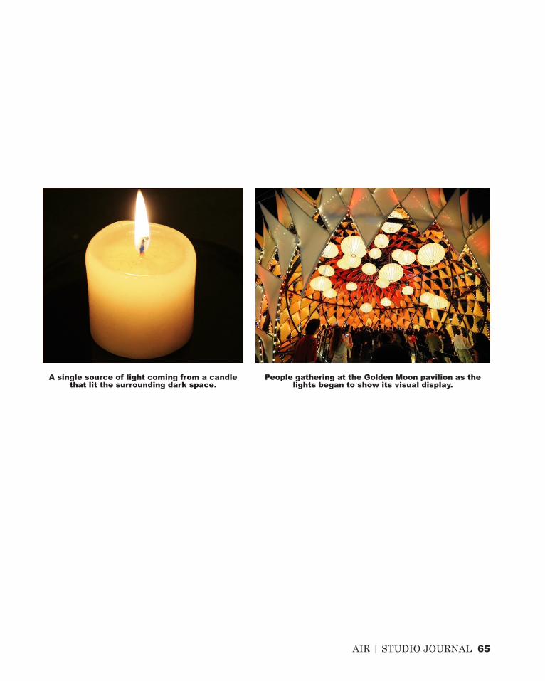
The concept of having a light pavilion out of many different options to build in this very huge site area is primarily taken from the idea of a candle. Although small in size, a candle can lit a large area of dark space and all attention is immediately drawn to this single source of light.
The same approach is to be pursued in my design proposal, where the interactive light show is only meant to be operating at night. Not only because during the day the solar energy is captured, stored and then used to generate energy for the lights to work but also it is during night where this pavilion works most efficiently. Through the visual display of LED panels on the pavilion’s skin, as what a candle implies in the middle of dark space, the pavilion will be noticeable clearly from afar, increasing the potential of people coming to the site.
It is also the intention to make more fluid the boundary between the industrial area of Refshaleøen and the city centre that is tried to be achieved through the lights display that represents the lively city full of lights and crowds.
In order to be recognisable, firstly there needs to be few LED panels that are already switched on automatically when the sun has set. Only after few lights have been on people are beginning to be aware of this pavilion, come together and join in with the interaction that is meant to be user-engaging. If the initial concept was to involve the users to simply step on and giving force to a panel installed on the floor which will then switch on another LED panel of the pavilion’s skin, further refinement is taken in terms of providing seats under each of the three pods. These seats will allow users to spend more time relaxing under the pods once they have engaged
with the so-called switching-on activity.
There have been numbers of lights pavilion that have succesfully achieved this, one of them is the Golden Moon project by LEAD. This temporary lighting installation successfully draw people’s attention through its varying colour of lights display that is further enchanced by its complex exposed lightweight structure.
Apart from installing photo-voltaic and LED panels on the pavilion’s skin, which is to generate solar energy and thus lighting the LED correspondingly, few clear glass panels will also be installed on some parts of the skin. The purpose is again to lessen the boundary between industrial and crowded city of Copenhagen, by which visitors of the pavilion will still be able to view the city skyline from afar through this glass panel.
AIR | STUDIO JOURNAL 65
A single source of light coming from a candle that lit the surrounding dark space.
People gathering at the Golden Moon pavilion as the lights began to show its visual display.

66 AIR | STUDIO JOURNAL
DESIGN CONCEPTC.1CITY LIGHTS PAVILION
The proposed design form consists of three equal pods that differ in its orientation and view. The first pod is facing the opposite harbour which is mainly the city skyline as seen from the site. This side will therefore not be fully covered with LED panels, instead a few of clear glass panels will be installed to make the view of the city skyline remain visible from the inside.
Similar to the second pod, this pod will also face building factories. This will benefit in that the pavilion will attract people not only from the opposite harbour but also being visually attractive to the industrial area of Refshaleøen.
Pod 1
Pod 3
Pod 2
The second pod might not have the best view amongst the other two pods, as this will be facing building factories that comprise the majority of Refshaleøen island.
AIR | STUDIO JOURNAL 67
Similar to the second pod, this pod will also face building factories. This will benefit in that the pavilion will attract people not only from the opposite harbour but also being visually attractive to the industrial area of Refshaleøen.
Pod 3
Pod 2
The second pod might not have the best view amongst the other two pods, as this will be facing building factories that comprise the majority of Refshaleøen island.

68 AIR | STUDIO JOURNAL
DESIGN CONCEPTC.1CITY LIGHTS PAVILION DIMENSION
20 m
70 m
39 m

AIR | STUDIO JOURNAL 69
This part is only to indicate the dimension of each individual pod and how it fits within the broader context of the site. Whilst the dimension of each is large, this is to accommodate large number of people gathering and relaxing underneath each pod which is 20 meters height. The large dimension of the pavilion is also to cope with the larger area of the site itself, making the pavilion noticeable even from a far distance, that is from the opposite harbour where the city is located.
179.71 m
70 AIR | STUDIO JOURNAL
DESIGN CONCEPTC.1SUN PATH ANALYSIS
N
kWh/m2
751.08<=
675.97
600.86
525.75
450.65
375.54
300.43
225.32
150.22
75.11
<=0.00
Copenhagen, Denmark1 Jan 1:00 - 7 Dec 24:00
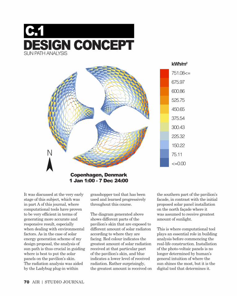
It was discussed at the very early stage of this subject, which was in part A of this journal, where computational tools have proven to be very efficient in terms of generating more accurate and responsive result, especially when dealing with environmental factors. As in the case of solar energy generation scheme of my design proposal, the analysis of sun path is thus crucial in guiding where is best to put the solar panels on the pavilion’s skin. The radiation analysis was aided by the Ladybug plug-in within
grasshopper tool that has been used and learned progressively throughout this course.
The diagram generated above shows different parts of the pavilion’s skin that are exposed to different amount of solar radiaton according to where they are facing. Red colour indicates the greatest amount of solar radiation received at that particular part of the pavilion’s skin, and blue indicates a lower level of received radiation. Rather surprisingly, the greatest amount is received on
the southern part of the pavilion’s facade, in contrast with the initial proposed solar panel installation on the north façade where it was assumed to receive greatest amount of sunlight.
This is where computational tool plays an essential role in building analysis before commencing the real-life construction. Installation of the photo-voltaic panels is no longer determined by human’s general intuition of where the sun shines the most, but it is the digital tool that determines it.

AIR | STUDIO JOURNAL 71
Having conducted the solar radiation analysis onto my design proposal, it was then decided that solar PV panels are only going to be installed on the pod where it is mostly exposed to the sun. This is not only to minimise the cost of installing the PV panels where they won’t receive enough sunlight, but also, the fact that Pod 1 (as shown in the above diagram) is facing the south and thus facing the industrial area of Refshaleøen will benefit in not blocking any view to the city across the harbour if the panels
were to be installed on Pod 2, where it sits closer to the harbour and simultaneously facing the city skyline.
During the analysis using Ladybug, there was an opportunity to make a correlation between the size of the hexagon cells and the area of higher annual radiation, in which the greater the amount of sunlight being exposed, the larger the cell is. If we remember on earlier attempt, lunchbox plug-in was used to generate the hexagon cells. Although the number of these cells
can be manipulated in its x and y direction, these however did not correspond to the amount of sunlight received. A more responsive hexagon or honeycomb skin can therefore be generated if this account is taken into consideration. However, as more focus will be given to the tectonic details in the next section, the hexagon cells will remain as it was originally intended. It is however worth knowing that such attempt can be made if I was to observe and analyse the effect of the sun path further.
1
2
3
72 AIR | STUDIO JOURNAL
DESIGN CONCEPTC.1DESIGN PROCESS
CURV
ESSU
RFAC
ESOF
FSET
SU
RFAC
ES
1
2
3
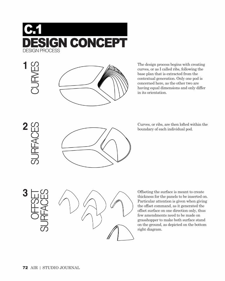
The design process begins with creating curves, or as I called ribs, following the base plan that is extracted from the contextual generation. Only one pod is concerned here, as the other two are having equal dimensions and only differ in its orientation.
Curves, or ribs, are then lofted within the boundary of each individual pod.
Offseting the surface is meant to create thickness for the panels to be inserted on. Particular attention is given when giving the offset command, as it generated the offset surface on one direction only, thus few amendments need to be made on grasshopper to make both surface stand on the ground, as depicted on the bottom right diagram.
AIR | STUDIO JOURNAL 73
HEXA
GON
SURF
ACE
FABR
ICAT
ION
TECT
ONIC
DE
TAILS
4
6
5
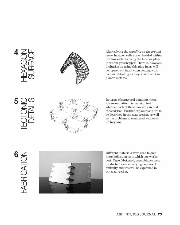
After solving the standing-on-the-ground issue, hexagon cells are embedded within the two surfaces using the luncbox plug-in within grasshopper. There is, however, limitation on using this plug-in, as will be figured out later when dealing with tectonic detailing as they won’t result in planar surfaces.
In terms of structural detailing, there are several attempts made to test whether each of these can work in real construction. Further explanations are to be described in the next section, as well as the problems encountered with each prototyping.
Different materials were used to give more indication as to which one works best. Once fabricated, assemblance were conducted, each in varying degrees of difficulty and this will be explained in the next section.

74 AIR | STUDIO JOURNAL
TECTONIC ELEMENTSC.2PROTOTYPING
Exploded isometric view of parts of the pavilion’s skin that is to be prototyped.
AIR | STUDIO JOURNAL 75
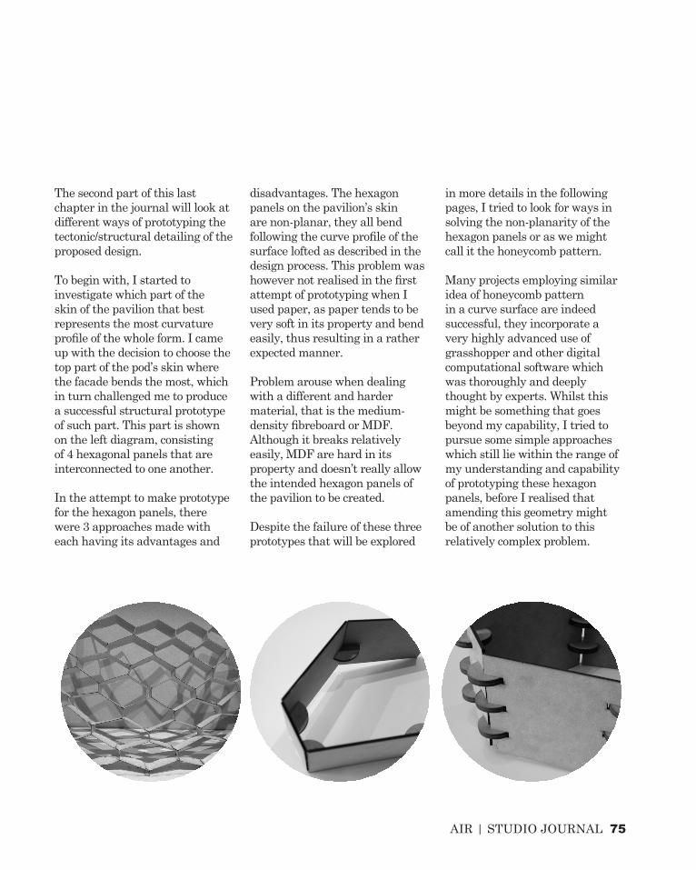
The second part of this last chapter in the journal will look at different ways of prototyping the tectonic/structural detailing of the proposed design.
To begin with, I started to investigate which part of the skin of the pavilion that best represents the most curvature profile of the whole form. I came up with the decision to choose the top part of the pod’s skin where the facade bends the most, which in turn challenged me to produce a successful structural prototype of such part. This part is shown on the left diagram, consisting of 4 hexagonal panels that are interconnected to one another.
In the attempt to make prototype for the hexagon panels, there were 3 approaches made with each having its advantages and
disadvantages. The hexagon panels on the pavilion’s skin are non-planar, they all bend following the curve profile of the surface lofted as described in the design process. This problem was however not realised in the first attempt of prototyping when I used paper, as paper tends to be very soft in its property and bend easily, thus resulting in a rather expected manner.
Problem arouse when dealing with a different and harder material, that is the medium-density fibreboard or MDF. Although it breaks relatively easily, MDF are hard in its property and doesn’t really allow the intended hexagon panels of the pavilion to be created.
Despite the failure of these three prototypes that will be explored
in more details in the following pages, I tried to look for ways in solving the non-planarity of the hexagon panels or as we might call it the honeycomb pattern.
Many projects employing similar idea of honeycomb pattern in a curve surface are indeed successful, they incorporate a very highly advanced use of grasshopper and other digital computational software which was thoroughly and deeply thought by experts. Whilst this might be something that goes beyond my capability, I tried to pursue some simple approaches which still lie within the range of my understanding and capability of prototyping these hexagon panels, before I realised that amending this geometry might be of another solution to this relatively complex problem.
1 AIR | STUDIO JOURNAL

AIR | STUDIO JOURNAL 2
PROTOTYPE 1:PAPER

78 AIR | STUDIO JOURNAL
TECTONIC ELEMENTSC.2PROTOTYPE 1: PAPER
Unrolled hexagon panel that was fabricated individually using paper.

AIR | STUDIO JOURNAL 79
The first material that came up to my mind in prototyping the hexagon panels was paper. This is because paper tends to be folded very easily, and the idea of folding is indeed my chosen material system to be analysed in part B of this journal.
It took only a while to fabricate this part of hexagon panels using paper which was then assembled. The assembly process was aided with PVA glue which proves to work very well with paper. Some edges of the paper were unfortunately left with some burned marks as this was fabricated using laser cut, and the relatively thin paper might not cope with the heat quite well. This problem might be overcome by
changing the method of printing to card cutting instead of laser cutting if I am to continue on using paper as my material for prototyping.
Though not all parts of the pavilion’s skin were fabricated and assembled using paper, fabricating only few parts of it was sufficient in making sure that paper allows this structure to work.
It was, however, not appropriate if an outdoor and exposed pavilion such as the City Lights Pavilion is constructed using paper. It was also the matter of size that was indicated earlier, which is relatively big and folding every single piece of paper might not
be the best way to construct this pavilion.
The approach to using paper in this first attempt is therefore only for the means of testing whether the hexagon panels, which at this very stage I have not yet come to the point of realising its non-planarity, can be folded and work structurally in real life.
Each individual hexagon was glued and connected to another hexagon, giving a result as shown on the picture above.

1 AIR | STUDIO JOURNAL

AIR | STUDIO JOURNAL 2
PROTOTYPE 2:MDF

82 AIR | STUDIO JOURNAL
TECTONIC ELEMENTSC.2PROTOTYPE 2: MEDIUM-DENSITY FIBREBOARD
Exploded surface of the hexagon panels which are to be connected using notches.
AIR | STUDIO JOURNAL 83
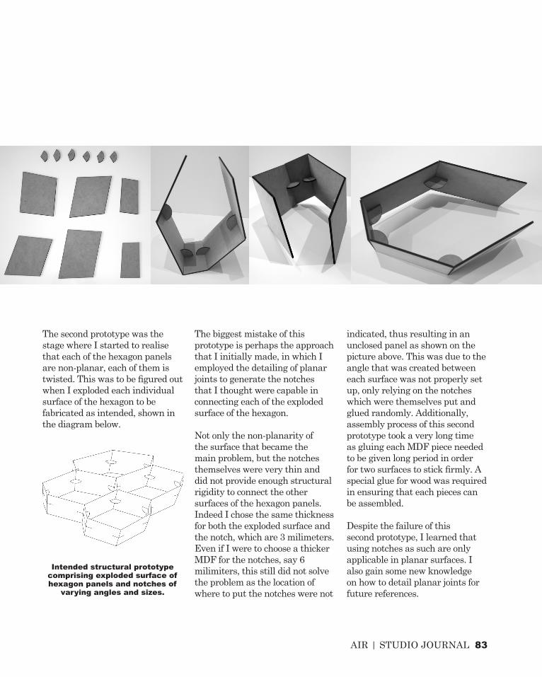
Intended structural prototype comprising exploded surface of hexagon panels and notches of
varying angles and sizes.
The second prototype was the stage where I started to realise that each of the hexagon panels are non-planar, each of them is twisted. This was to be figured out when I exploded each individual surface of the hexagon to be fabricated as intended, shown in the diagram below.
The biggest mistake of this prototype is perhaps the approach that I initially made, in which I employed the detailing of planar joints to generate the notches that I thought were capable in connecting each of the exploded surface of the hexagon.
Not only the non-planarity of the surface that became the main problem, but the notches themselves were very thin and did not provide enough structural rigidity to connect the other surfaces of the hexagon panels. Indeed I chose the same thickness for both the exploded surface and the notch, which are 3 milimeters. Even if I were to choose a thicker MDF for the notches, say 6 milimiters, this still did not solve the problem as the location of where to put the notches were not
indicated, thus resulting in an unclosed panel as shown on the picture above. This was due to the angle that was created between each surface was not properly set up, only relying on the notches which were themselves put and glued randomly. Additionally, assembly process of this second prototype took a very long time as gluing each MDF piece needed to be given long period in order for two surfaces to stick firmly. A special glue for wood was required in ensuring that each pieces can be assembled.
Despite the failure of this second prototype, I learned that using notches as such are only applicable in planar surfaces. I also gain some new knowledge on how to detail planar joints for future references.

1 AIR | STUDIO JOURNAL

AIR | STUDIO JOURNAL 2
PROTOTYPE 3:MDF

86 AIR | STUDIO JOURNAL
TECTONIC ELEMENTSC.2PROTOTYPE 3: MEDIUM-DENSITY FIBREBOARD
Individual pieces of exploded hexagon panels with indicated location of
notches.

AIR | STUDIO JOURNAL 87
Still using MDF, I changed the approach of prototyping this structural jointing of hexagon panels in terms of how each individual piece is joined. If the previous attempt did not consider the location of the notches, thus resulting in an unresolved panel, this time each notch, which is basically a circle, was given specified location on each exploded surface according to the angle that will generate the bending profile of the hexagon panels.
All notches, or circles, are of equal sizes, thus it was rather easy to choose any kind of material that was intended to be used for real-site construction. However, for the purpose of prototyping, MDF was preferred. These notches, consisting of three for each corner of the panels, are placed perpendicular to the intersecting curve between the edges of the surfaces.
Assembly process of this prototype was done much quicker than the previous one, indeed no glue was even required. However, this attempt unfortunately fails to prove that the joints can work structurally. This is clearly shown by the gaps created between the non-planar surfaces of the exploded panels, which was treated as planar in the fabrication process after being unrolled.Although the third prototype
seems to be more structurally stable than the second one, this type of joints are not feasible in a larger scale construction. The circle-shaped notches did not provide any safe connection, by which I mean the lack of interlocking joints between the notch and the surface. The surface can therefore move, or slip, very easily due to the absence of interlocking joints with the notches. This will certainly cause a problem during the construction process if such jointing was to be applied.
Given that all three prototypes fail to prove any structural rigidity of the proposed design form using 2D fabrication process, I have thus decided to make an amendment to the geometry that I initially intended. The last section of part C will further describe this in more details.
Three notches connecting each individual exploded surface of the
hexagon panel.

88 AIR | STUDIO JOURNAL

AIR | STUDIO JOURNAL 89
This prototype fails to prove structural stability and rigidity, as shown by the gap created between the surface.

90 AIR | STUDIO JOURNAL
FINAL DETAIL MODELC.3AMENDED GEOMETRY
The attempt to build hexagon, or honeycomb, panels on the pavilion’s skin wasn’t successful due to the non-planarity of each individual cell. The prototypes that were tested could only be realised if the hexagon cells are planar. Therefore, I started to figure out ways to overcoming this problem by first looking at few possible options.
I realised that since the design proposal began to develop, there was no clear argument as to why I stick with the hexagon panels out of many other different geometries. It is indeed true that the hexagon cells can be used to represent the pattern of honeycomb, in which case the application of biomimicry was entailed. Yet, panelling hexagons are only a way to communicate the means of projecting the light show on the City Lights Pavilion. Other method of panelling, thus not limited to hexagons, can still equally convey similar meanings of representing the idea
of a light pavilion. Therefore, I started to prepare an amended geometry for my design proposal, which consists of similar ideas of panelling where the solar PV panels, LED panels and the clear glass panels are to be installed on.
Maintaining the same form which was derived from parametric tools as described earlier, the amended geometry that was chosen consists of ribs structures which represent the contour of the lofted surface. The waffle system employed in this amended geometry is proven to be more feasible, not only that it allows 2D fabrication process to be conducted and built, but also it proves to show a more stable and rigid structure, in comparison with the prototypes built previously.
This amended geometry also enable the panelling system that was intended, where the only difference is that this is now made up of rectangular pieces instead of hexagon cells. Whilst a
more stable structure can now be achieved, it is important to note that during construction process labelling must be done for each individual unrolled piece so that assembly process can be done quickly and accurately. Having the individual pieces numbered will not only allow a more organised construction but also enable a quicker solution should any piece is damaged or broken during construction.
The diagram on the right shows how each rib fits into another, where the connection is locked, something that was missing in the prototype for the hexagon panels.
By not limiting the option of panelling to hexagon, I can therefore explore further possibilities and come up with a new solution to my design proposal.

AIR | STUDIO JOURNAL 91
The rib system of the pavilion’s skin showing the interlocking joints between each rib.
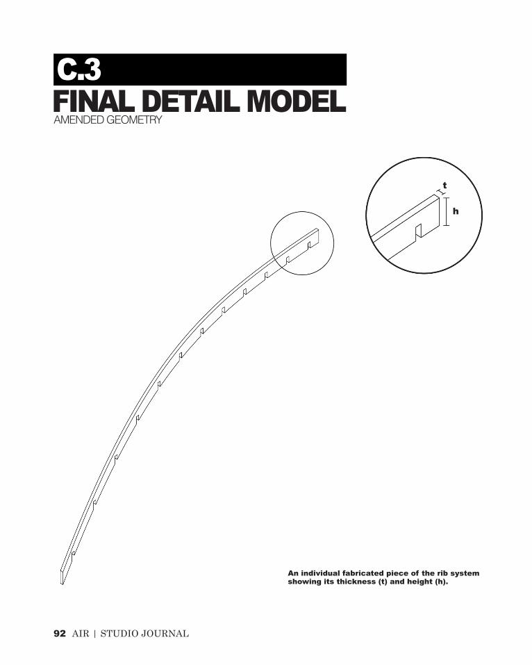
92 AIR | STUDIO JOURNAL
FINAL DETAIL MODELC.3AMENDED GEOMETRY
t
h
An individual fabricated piece of the rib system showing its thickness (t) and height (h).
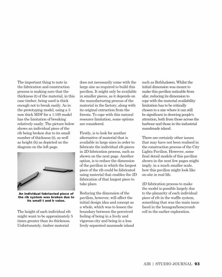
AIR | STUDIO JOURNAL 93
The important thing to note in the fabrication and construction process is making sure that the thickness (t) of the material, in this case timber, being used is thick enough not to break easily. As in the prototyping model, using a 3 mm thick MDF for a 1:100 model has the limitation of breaking relatively easily. The picture below shows an individual piece of the rib being broken due to its small number of thickness (t), as well as height (h) as depicted on the diagram on the left page.
The height of each individual rib might want to be approximately 5 times greater than its thickness. Unfortunately, timber material
does not necessarily come with the large size as required to build this pavilion. It might only be available in smaller pieces, as it depends on the manufacturing process of the material in the factory, along with its original extraction from the forests. To cope with this natural resource limitation, some options are considered.
Firstly, is to look for another alternative of material that is available in large sizes in order to fabricate the individual rib pieces in 2D fabrication process, such as shown on the next page. Another option, is to reduce the dimension of the pavilion in which the largest piece of the rib could be fabricated using material that enables the 2D fabrication of that largest piece to take place.
Reducing the dimension of the pavilion, however, will affect the initial design idea and concept as a whole, which was to lessen the boundary between the perceived feeling of being in a lively and vigorous city and being in a less lively separated manmade island
such as Refshaleøen. Whilst the initial dimension was meant to make this pavilion noticable from afar, reducing its dimension to cope with the material availability limitation has to be critically chosen to a size where it can still be significant in drawing people’s attention, both from those across the harbour and those in the industrial mandmade island.
There are certainly other issues that may have not been realised in the construction process of the City Lights Pavilion. However, some final detail models of this pavilion shown in the next few pages might imply, in a much smaller scale, how this pavilion might look like on-site in real life.
2D fabrication process to make the model is possible largely due to the planarity of each individual piece of rib in the waffle system, something that was the main issue faced in the hexagon/honeycomb cell in the earlier exploration.
An individual fabriacted piece of the rib system was broken due to
its small t and h value.

94 AIR | STUDIO JOURNAL
FINAL DETAIL MODELC.3
Unrolled pieces to be fabricated

AIR | STUDIO JOURNAL 95
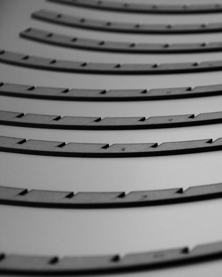
1 AIR | STUDIO JOURNAL

AIR | STUDIO JOURNAL 2
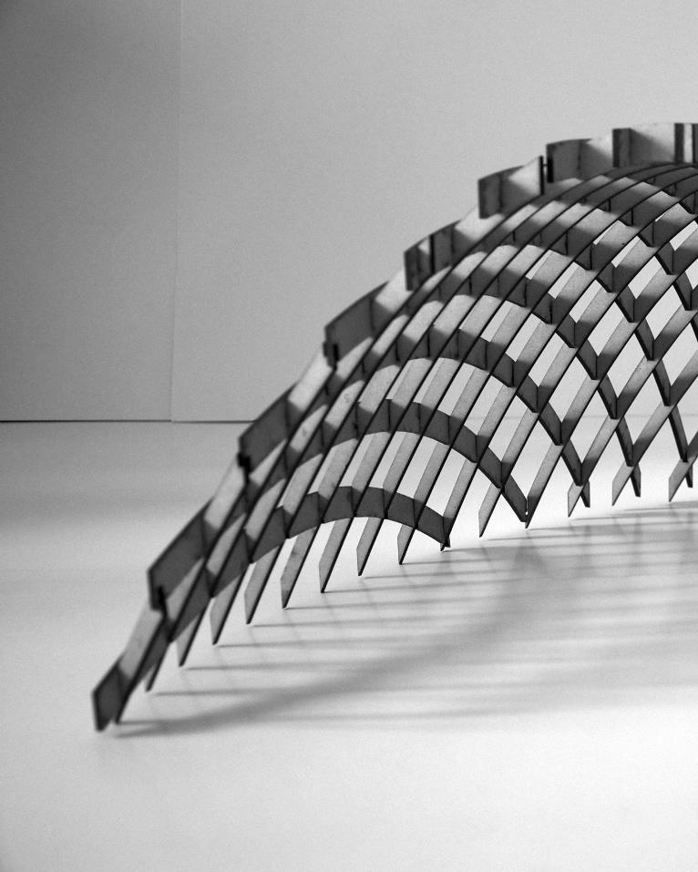
1 AIR | STUDIO JOURNAL

AIR | STUDIO JOURNAL 99
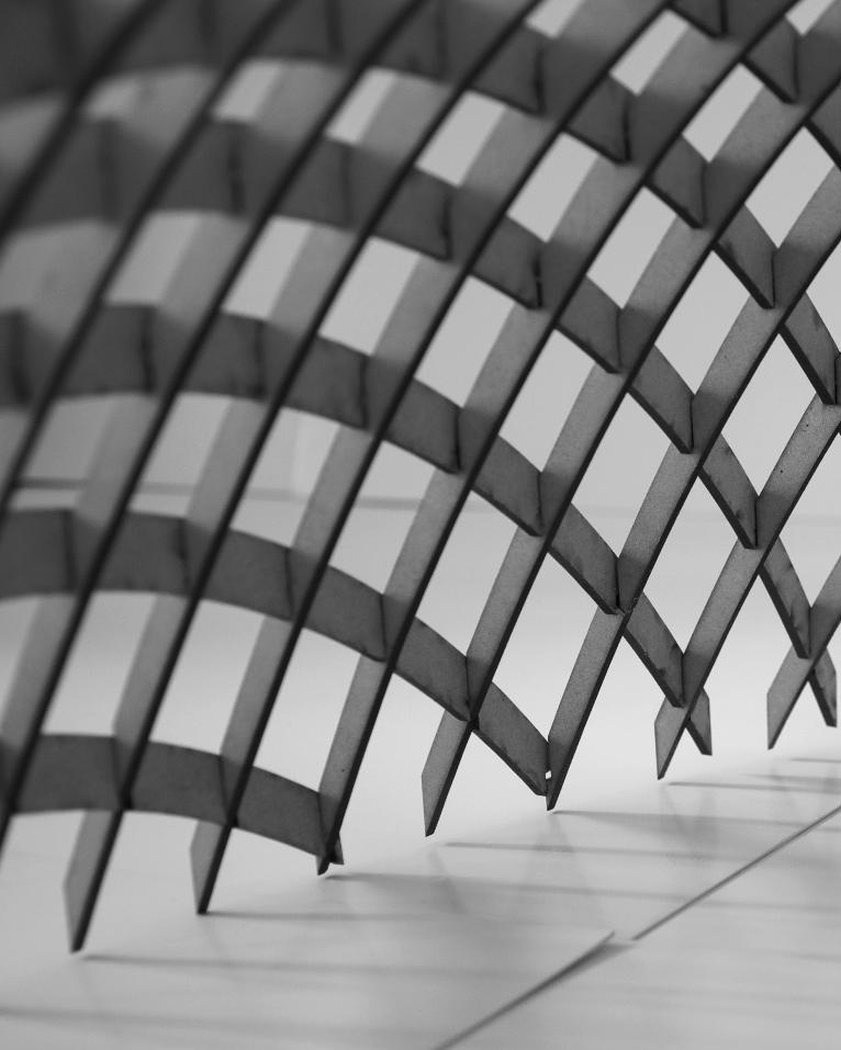
98 AIR | STUDIO JOURNAL
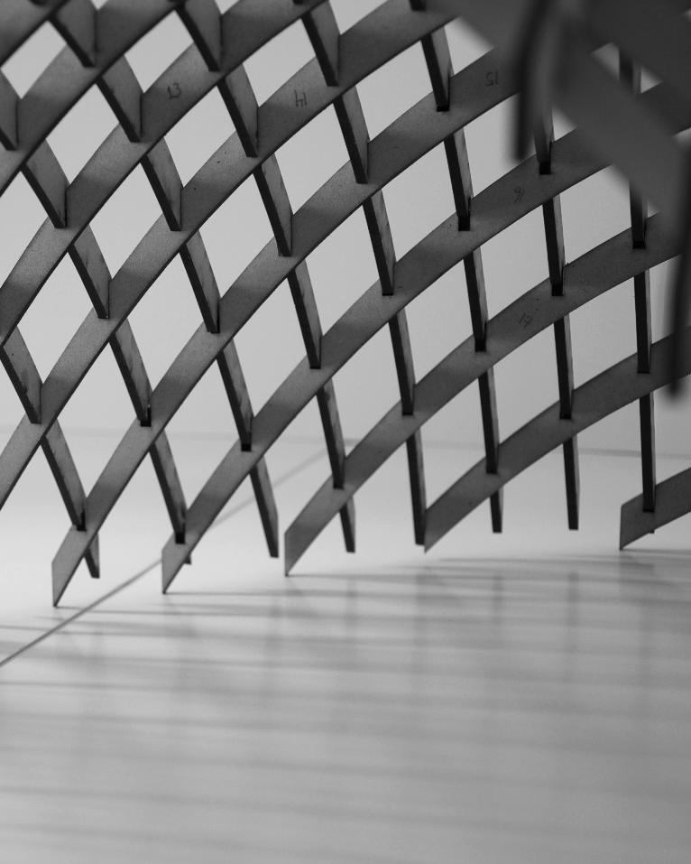
AIR | STUDIO JOURNAL 99
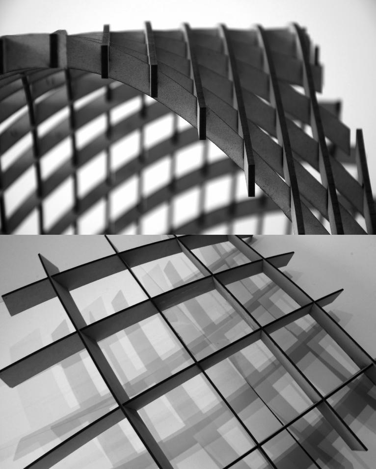
1 AIR | STUDIO JOURNAL

AIR | STUDIO JOURNAL 2
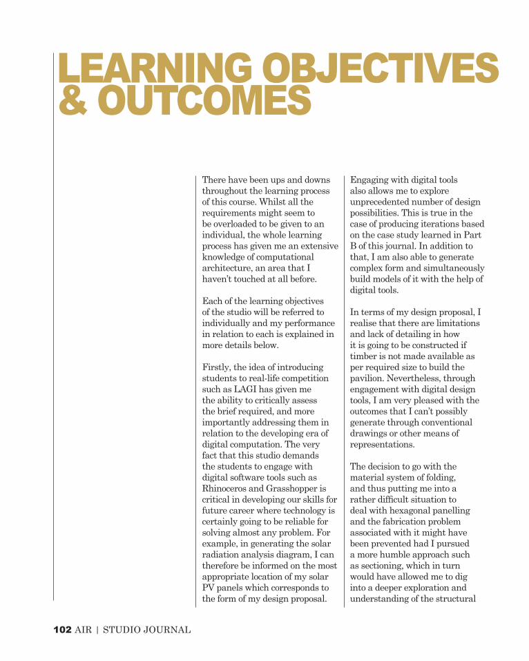
102 AIR | STUDIO JOURNAL
There have been ups and downs throughout the learning process of this course. Whilst all the requirements might seem to be overloaded to be given to an individual, the whole learning process has given me an extensive knowledge of computational architecture, an area that I haven’t touched at all before.
Each of the learning objectives of the studio will be referred to individually and my performance in relation to each is explained in more details below.
Firstly, the idea of introducing students to real-life competition such as LAGI has given me the ability to critically assess the brief required, and more importantly addressing them in relation to the developing era of digital computation. The very fact that this studio demands the students to engage with digital software tools such as Rhinoceros and Grasshopper is critical in developing our skills for future career where technology is certainly going to be reliable for solving almost any problem. For example, in generating the solar radiation analysis diagram, I can therefore be informed on the most appropriate location of my solar PV panels which corresponds to the form of my design proposal.
Engaging with digital tools also allows me to explore unprecedented number of design possibilities. This is true in the case of producing iterations based on the case study learned in Part B of this journal. In addition to that, I am also able to generate complex form and simultaneously build models of it with the help of digital tools.
In terms of my design proposal, I realise that there are limitations and lack of detailing in how it is going to be constructed if timber is not made available as per required size to build the pavilion. Nevertheless, through engagement with digital design tools, I am very pleased with the outcomes that I can’t possibly generate through conventional drawings or other means of representations.
The decision to go with the material system of folding, and thus putting me into a rather difficult situation to deal with hexagonal panelling and the fabrication problem associated with it might have been prevented had I pursued a more humble approach such as sectioning, which in turn would have allowed me to dig into a deeper exploration and understanding of the structural
LEARNING OBJECTIVES & OUTCOMES

AIR | STUDIO JOURNAL 103
jointing. It however has been an invaluable experience to have dealt with such complex geometry where I discovered many new knowledges about different types of jointing in hexagon panels of different curvature profile, which again, I have to say that understanding the logic and thus visually programming it into grasshopper script is something that is beyond my capability.
Throughout the design process, I have found that having a strong and clear concept is crucial to make the rest of the processes much easier to develop and refined. Prototyping plays an important role in figuring out whether something that seems to work digitally really works in real life. This has been proven with the prototyping I have done for the proposal, in which I learn that every detail needs to be taken care of to ensure that my design is feasible to be built using 2D fabrication process. It is also in prototyping where I learned that the technique I
pursued, which was the hexagon panelling, was fully succesful yet understanding its limitations has allowed me to gain another lesson of digital fabrication.
The attempt to amend the original geometry that I pursued was done as part of overcoming the problem I was dealing with with the hexagon/honeycomb panelling. This amendment shows that a simpler approach could eventually lead to a more feasible construction.
Now that the studio has come to an end, my perspective towards digital architecture has shifted to a more engaging level where I have put myself into digital computational tools throughout the design process of this studio’s task. I have been more than ensured that in the future, digital tools are certainly going to be useful in the career of architecture not only to make the whole process easier such as environmental analysis but also to allow the generation of unexpected outcomes.
AIR | STUDIO JOURNAL 103

104 AIR | STUDIO JOURNAL
http://uberfacts.files.wordpress.com/2013/07/candle-flame-no-reflection.jpghttp://l-e-a-d.pro/projects/golden-moon/2664
References

AIR | STUDIO JOURNAL 103
THE ENDSTUDIO JOURNAL