Structured Lighting - Scientific Computing and Imaging...
48
Structured Lighting Guido Gerig CS 6320, 3D Computer Vision Spring 2013 (credits: slides S. Narasimhan CMU, Marc Pollefeys UNC) http://mesh.brown.edu/byo3d http://www.cs.cmu.edu/afs/cs/academic/class/15385- s06/lectures/ppts/lec-17.ppt
Transcript of Structured Lighting - Scientific Computing and Imaging...
Structured Lighting Guido Gerig
CS 6320, 3D Computer Vision
Spring 2013 (credits: slides S. Narasimhan CMU, Marc
Pollefeys UNC)
http://mesh.brown.edu/byo3d http://www.cs.cmu.edu/afs/cs/academic/class/15385-
s06/lectures/ppts/lec-17.ppt
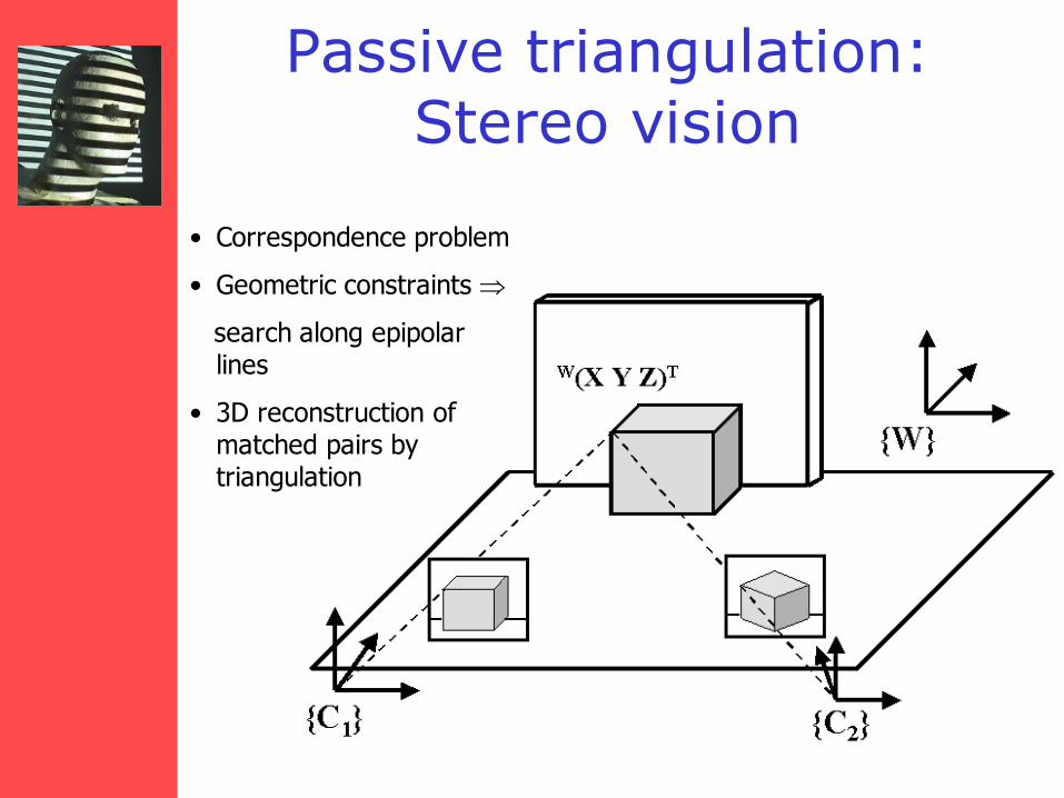
Passive triangulation: Stereo vision
• Correspondence problem
• Geometric constraints
search along epipolar lines
• 3D reconstruction of matched pairs by triangulation
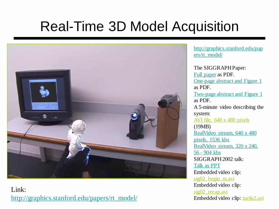
Real-Time 3D Model Acquisition
Link:
http://graphics.stanford.edu/papers/rt_model/
http://graphics.stanford.edu/pap
ers/rt_model/
The SIGGRAPH Paper:
Full paper as PDF.
One-page abstract and Figure 1
as PDF.
Two-page abstract and Figure 1
as PDF.
A 5-minute video describing the
system:
AVI file, 640 x 480 pixels
(19MB)
RealVideo stream, 640 x 480
pixels, 1536 kbs
RealVideo stream, 320 x 240,
56 - 904 kbs
SIGGRAPH 2002 talk:
Talk as PPT
Embedded video clip:
sig02_begin_m.avi
Embedded video clip:
sig02_recap.avi
Embedded video clip: turtle2.avi
Structured Light

Basic Principle
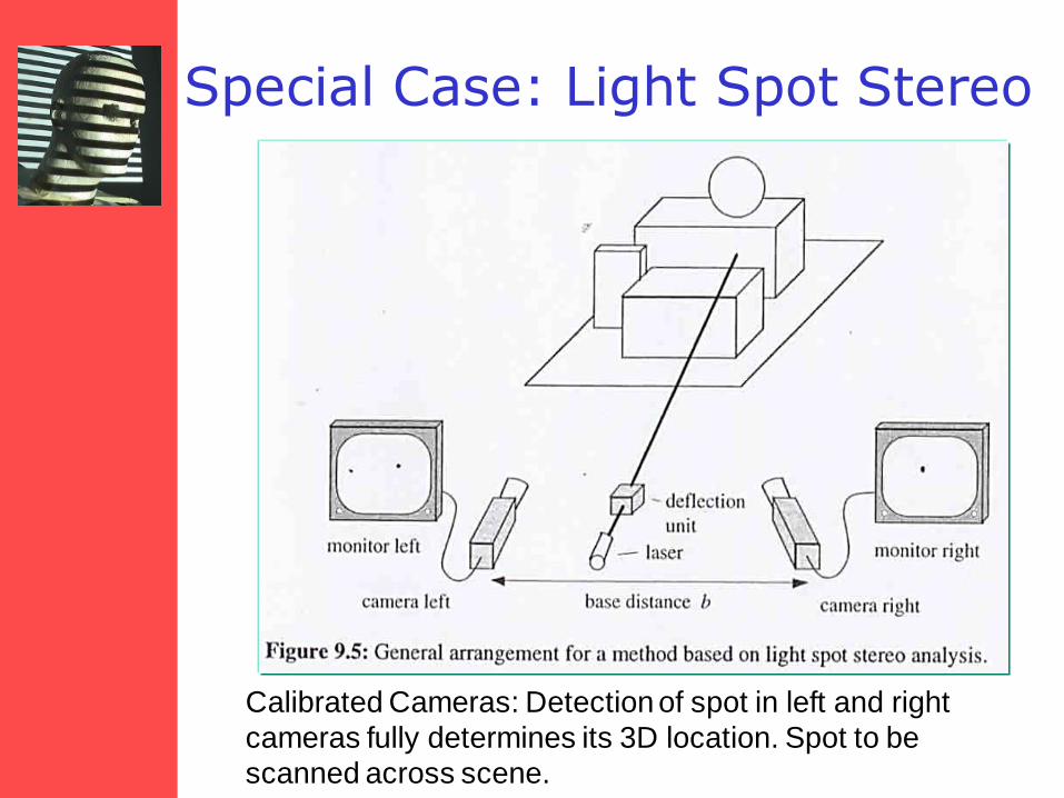
Special Case: Light Spot Stereo
Calibrated Cameras: Detection of spot in left and right
cameras fully determines its 3D location. Spot to be
scanned across scene.
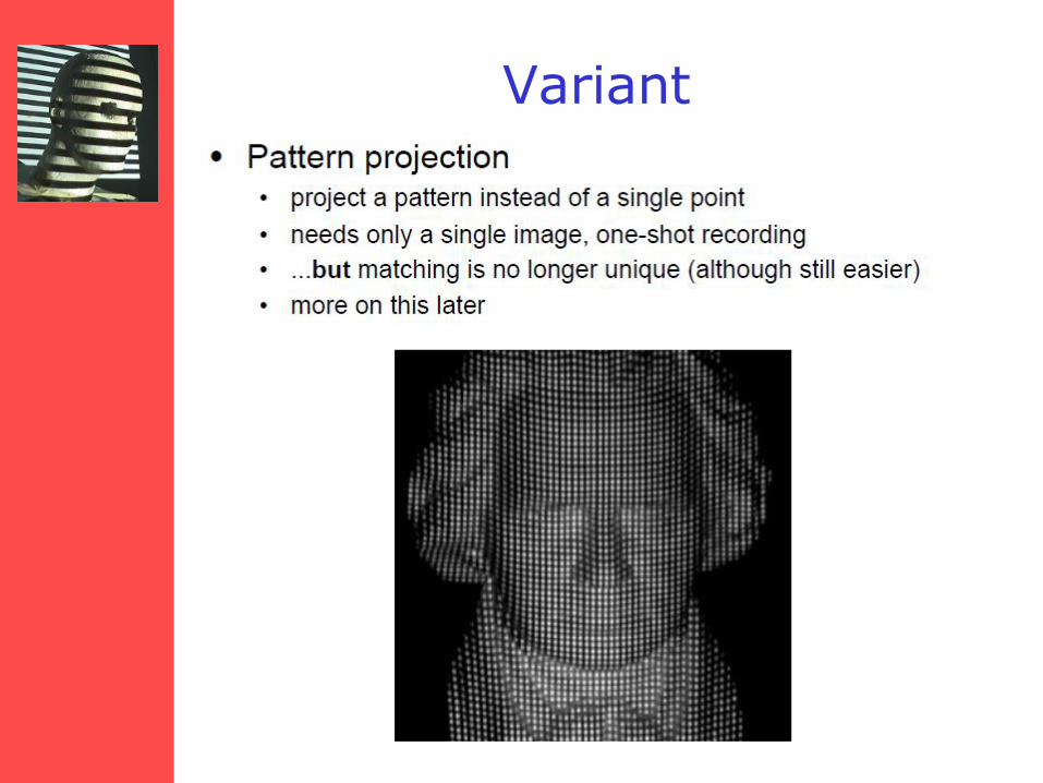
Variant
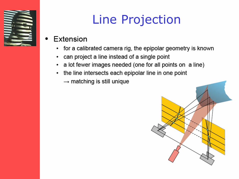
Line Projection
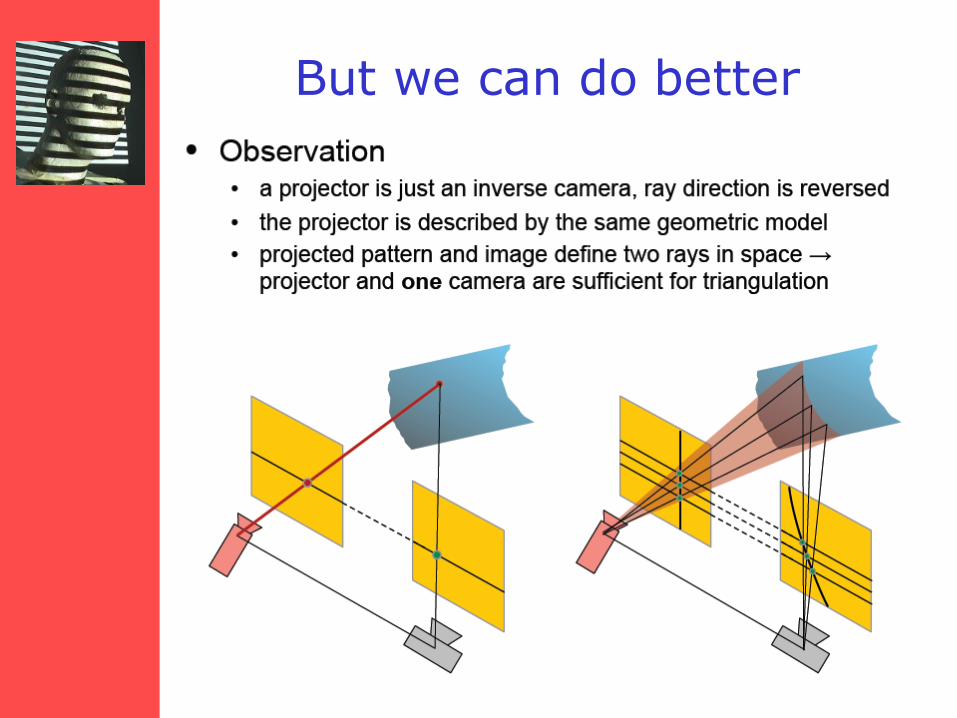
But we can do better
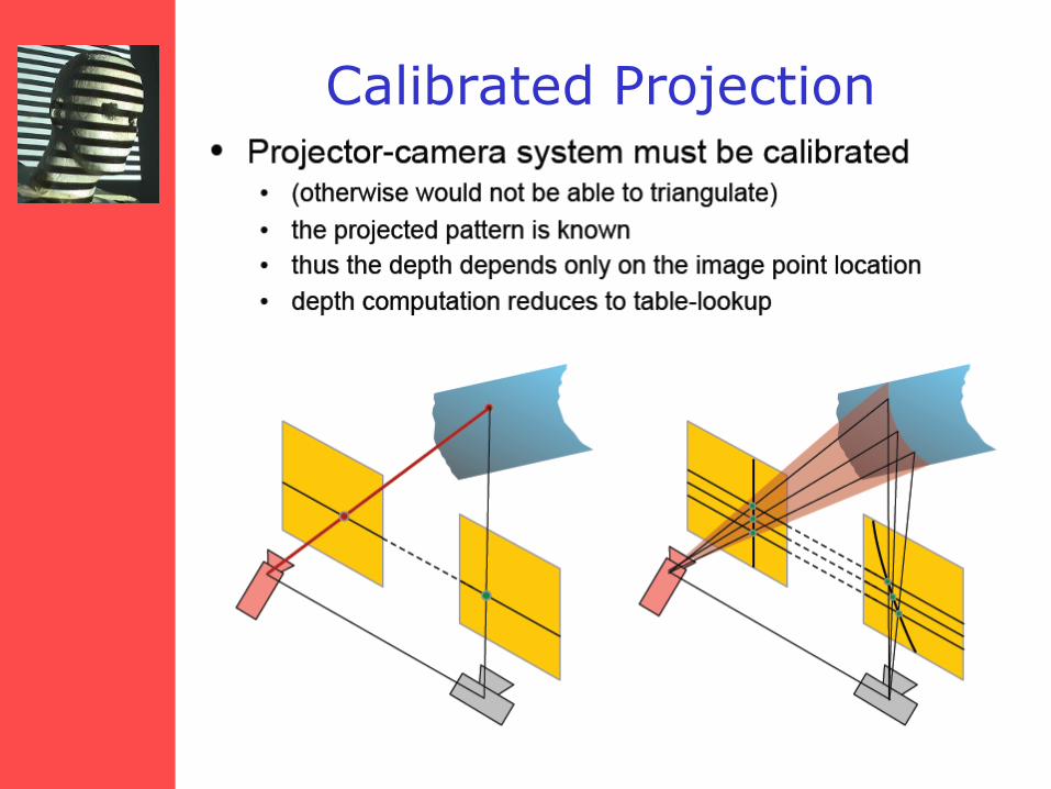
Calibrated Projection
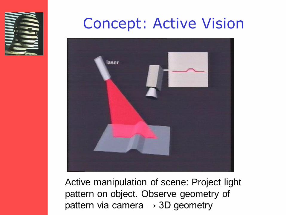
Concept: Active Vision
Active manipulation of scene: Project light
pattern on object. Observe geometry of
pattern via camera → 3D geometry
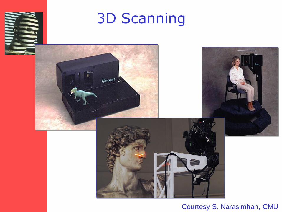
3D Scanning
Courtesy S. Narasimhan, CMU

Typical Application
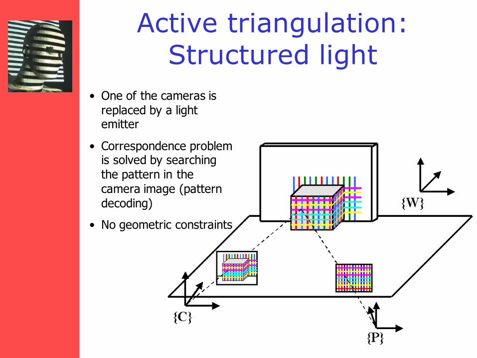
Active triangulation: Structured light
• One of the cameras is replaced by a light emitter
• Correspondence problem is solved by searching the pattern in the camera image (pattern decoding)
• No geometric constraints

Overview
• Background
• General Setup
• Light Point Projection 2D and 3D
• Light Stripe Projection
• Static Light Pattern Projection
– Binary Encoded Light Stripes
– Segmenting Stripes
• 3D Photography on Your Desk
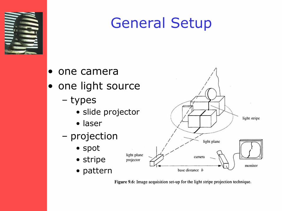
General Setup
• one camera
• one light source
– types
• slide projector
• laser
– projection
• spot
• stripe
• pattern
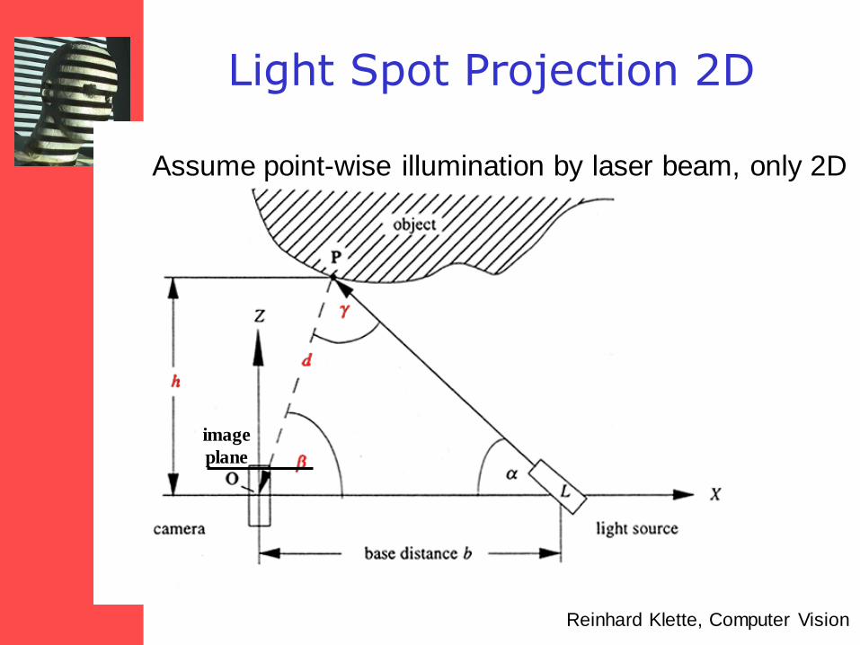
Light Spot Projection 2D
image
plane
Assume point-wise illumination by laser beam, only 2D
Reinhard Klette, Computer Vision
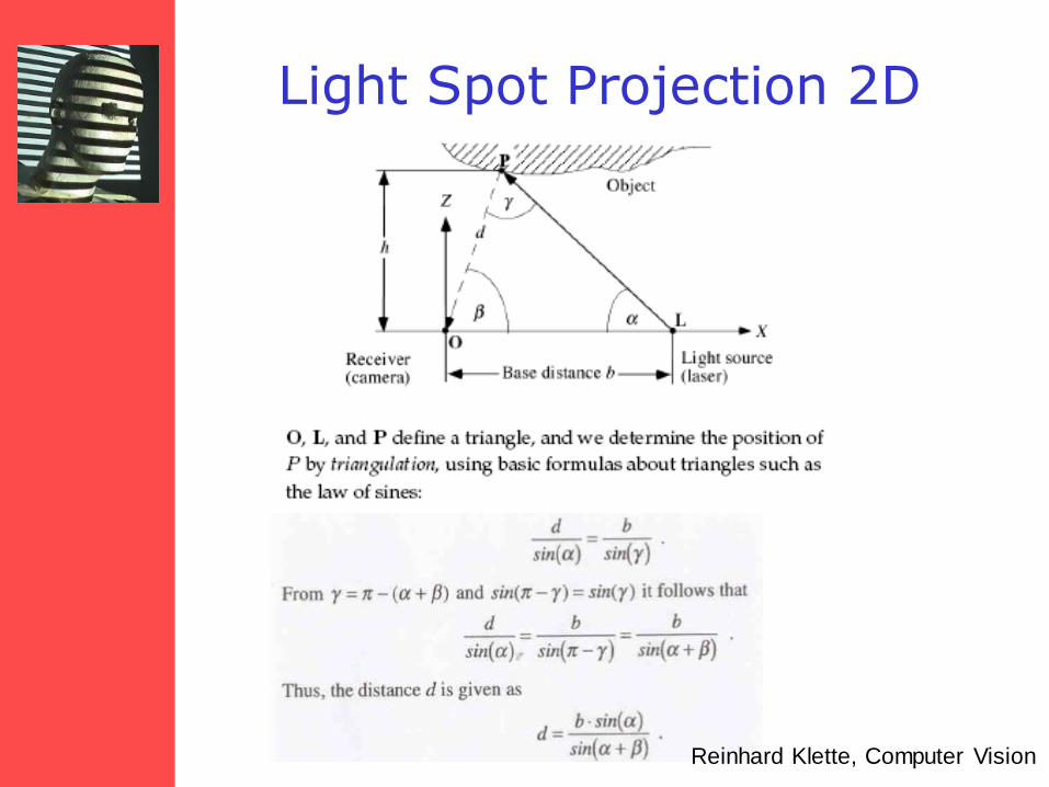
Light Spot Projection 2D
Reinhard Klette, Computer Vision
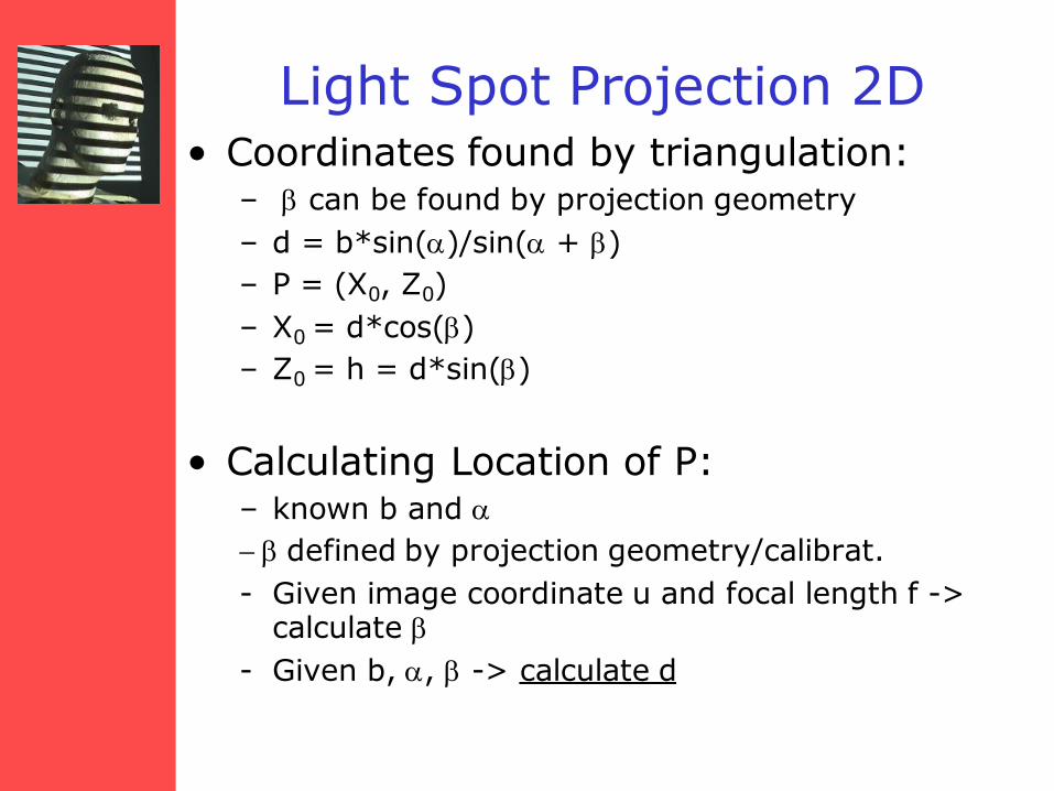
Light Spot Projection 2D • Coordinates found by triangulation:
– b can be found by projection geometry
– d = b*sin(a)/sin(a + b)
– P = (X0, Z0)
– X0 = d*cos(b)
– Z0 = h = d*sin(b)
• Calculating Location of P: – known b and a
- b defined by projection geometry/calibrat.
- Given image coordinate u and focal length f -> calculate b
- Given b, a, b -> calculate d

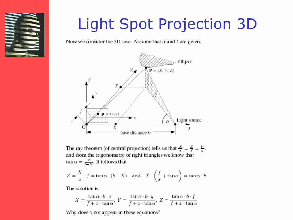
Light Spot Projection 3D
Z
Light Spot Projection 3D
Light Spot Projection 3D
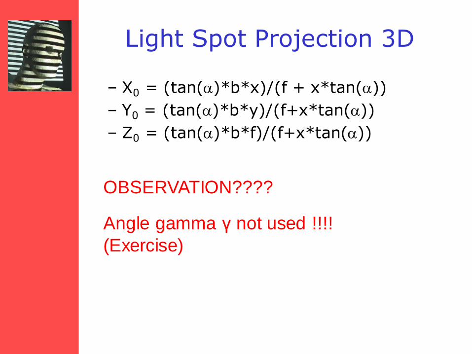
– X0 = (tan(a)*b*x)/(f + x*tan(a))
– Y0 = (tan(a)*b*y)/(f+x*tan(a))
– Z0 = (tan(a)*b*f)/(f+x*tan(a))
OBSERVATION????
Angle gamma γ not used !!!!
(Exercise)
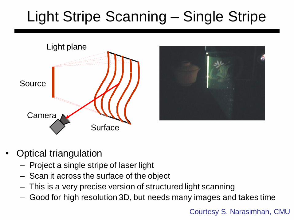
Light Stripe Scanning – Single Stripe
Camera
Source
Surface
Light plane
• Optical triangulation – Project a single stripe of laser light
– Scan it across the surface of the object
– This is a very precise version of structured light scanning
– Good for high resolution 3D, but needs many images and takes time
Courtesy S. Narasimhan, CMU
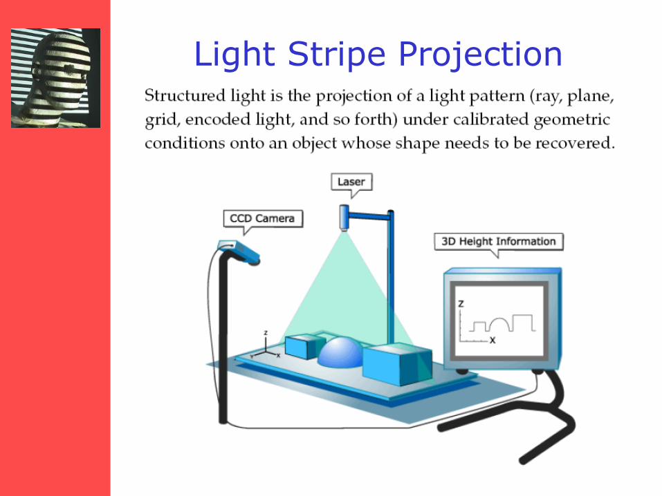
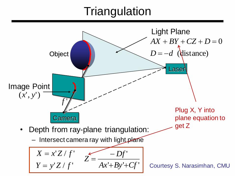
Light Stripe Projection

Triangulation
• Project laser stripe onto object
Object
Laser
Camera
Light Plane 0 DCzByAx
Courtesy S. Narasimhan, CMU
Camera
Triangulation
• Depth from ray-plane triangulation:
– Intersect camera ray with light plane
Laser
Object
Light Plane
(distance)
0
dD
DCZBYAX
-
)','( yxImage Point
'/'
'/'
fZyY
fZxX
'''
'
CfByAx
DfZ
-
Courtesy S. Narasimhan, CMU
Plug X, Y into
plane equation to
get Z
'f
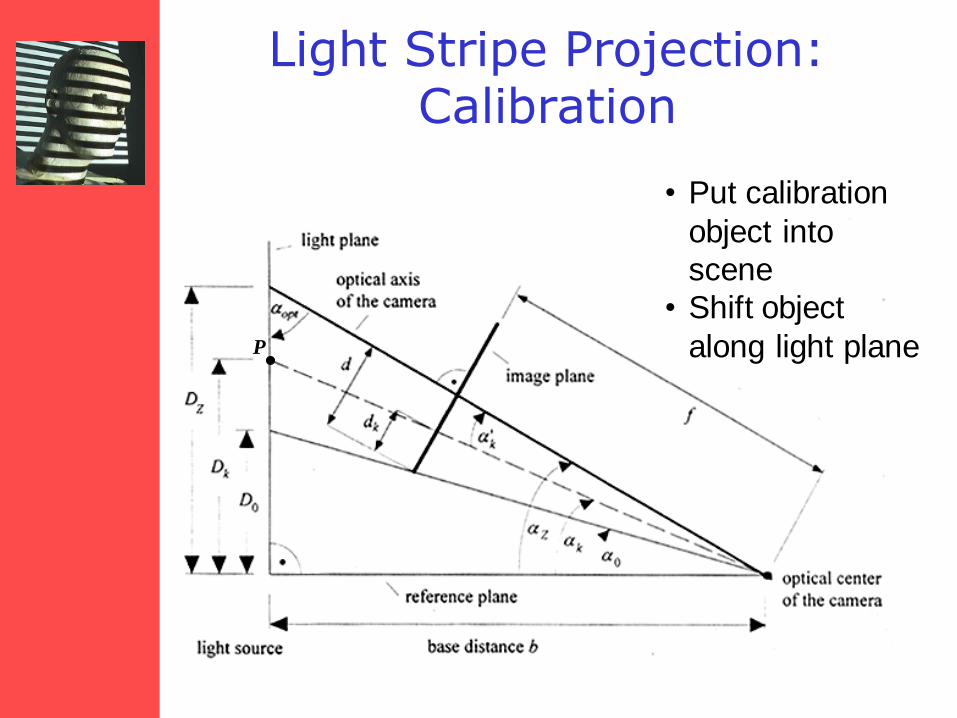
Light Stripe Projection: Calibration
P
• Put calibration
object into
scene
• Shift object
along light plane
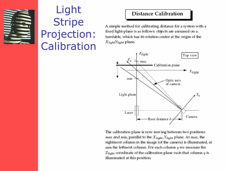
Light Stripe
Projection: Calibration
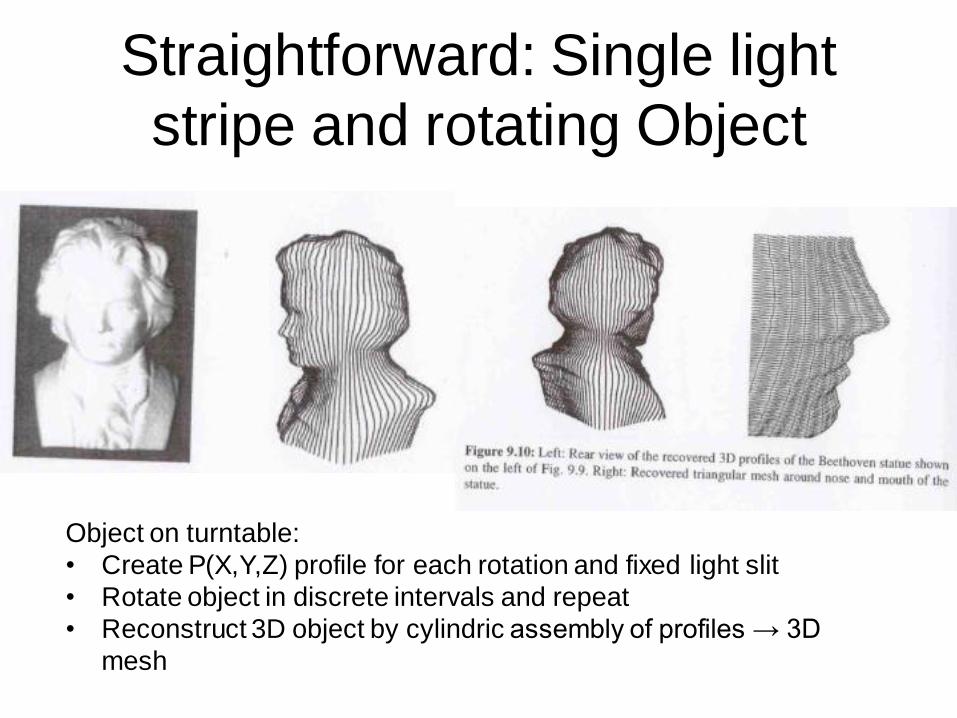
Straightforward: Single light
stripe and rotating Object
Object on turntable:
• Create P(X,Y,Z) profile for each rotation and fixed light slit
• Rotate object in discrete intervals and repeat
• Reconstruct 3D object by cylindric assembly of profiles → 3D
mesh
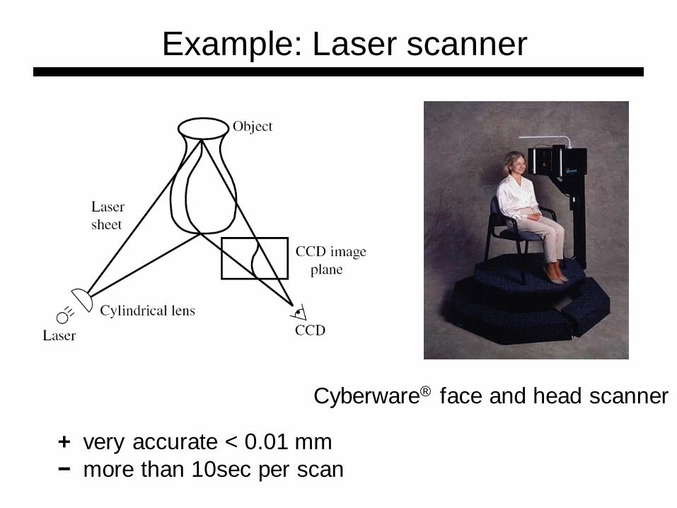
Example: Laser scanner
Cyberware® face and head scanner
+ very accurate < 0.01 mm
− more than 10sec per scan
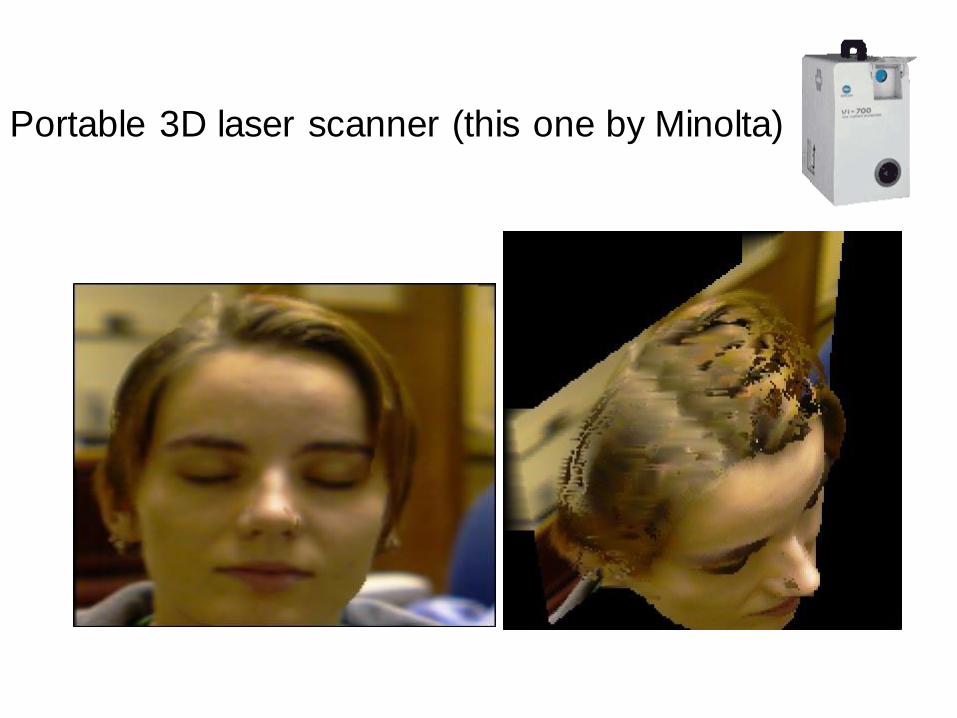
Portable 3D laser scanner (this one by Minolta)
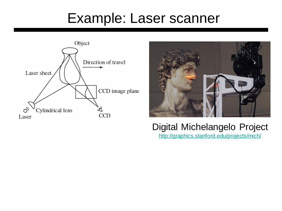
Digital Michelangelo Project http://graphics.stanford.edu/projects/mich/
Example: Laser scanner

Can we do it without
expensive equipment?
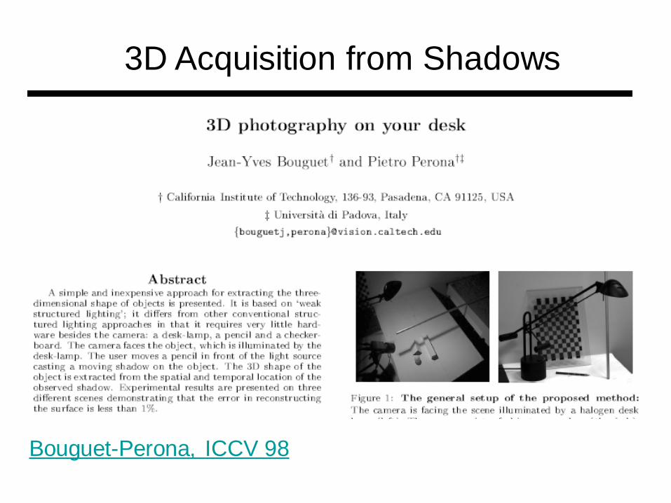
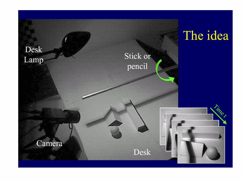
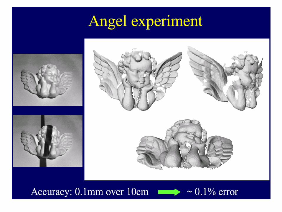
3D Acquisition from Shadows
Bouguet-Perona, ICCV 98
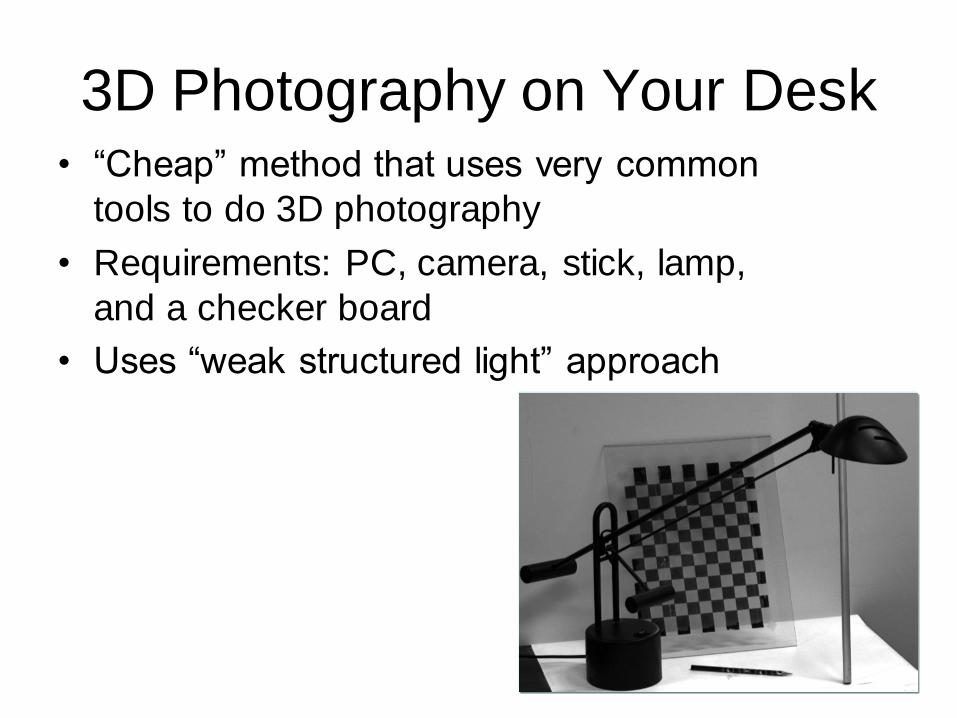
3D Photography on Your Desk • “Cheap” method that uses very common
tools to do 3D photography
• Requirements: PC, camera, stick, lamp,
and a checker board
• Uses “weak structured light” approach

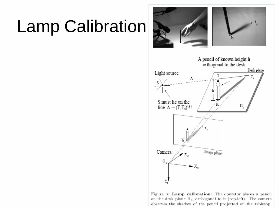
Lamp Calibration


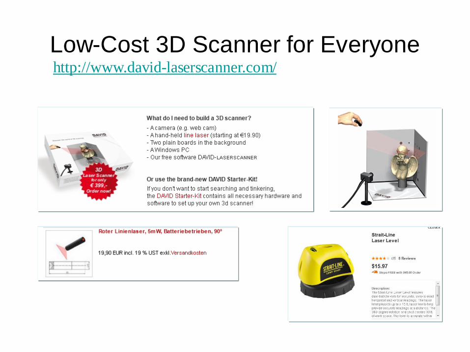
Low-Cost 3D Scanner for Everyone http://www.david-laserscanner.com/

Low-Cost 3D Scanner for Everyone http://www.david-laserscanner.com/wiki/user_manual/3d_laser_scanning

Cheap Scanner
• http://www.igp.ethz.ch/photogrammetry/education/lehrveranstaltungen
/MachineVisionFS2011/coursematerial/MV-SS2011-structured.pdf
• Cheap Scanner: http://www.david-laserscanner.com/

Build your own 3D scanner
• Course notes: http://mesh.brown.edu/byo3d/notes/byo3D.pdf
• Slides: http://mesh.brown.edu/byo3d/slides.html
• Source code: http://mesh.brown.edu/byo3d/source.html
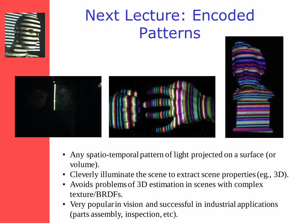
Next Lecture: Encoded Patterns
• Any spatio-temporal pattern of light projected on a surface (or
volume).
• Cleverly illuminate the scene to extract scene properties (eg., 3D).
• Avoids problems of 3D estimation in scenes with complex
texture/BRDFs.
• Very popular in vision and successful in industrial applications
(parts assembly, inspection, etc).