
Shape from Silhouettes I - Scientific Computing and...
49
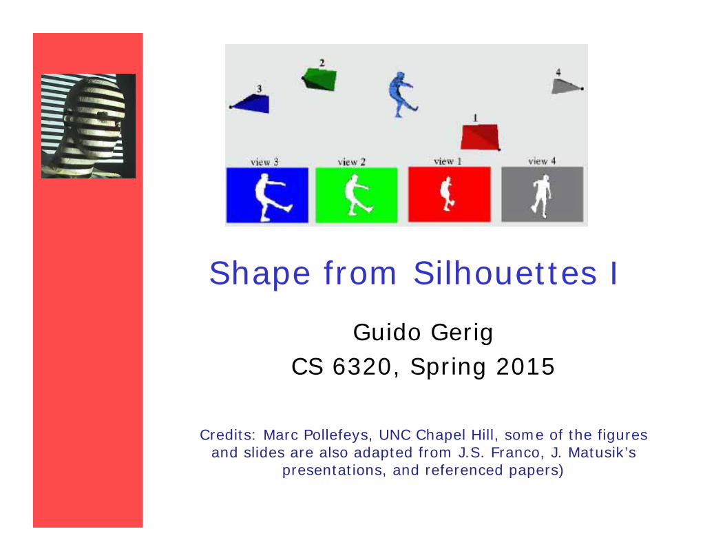
Shape from Silhouettes I Guido Gerig CS 6320, Spring 2015 Credits: Marc Pollefeys, UNC Chapel Hill, some of the figures and slides are also adapted from J.S. Franco, J. Matusik’s presentations, and referenced papers)
Transcript of Shape from Silhouettes I - Scientific Computing and...
Shape from Silhouettes I
Guido GerigCS 6320, Spring 2015
Credits: Marc Pollefeys, UNC Chapel Hill, some of the figures and slides are also adapted from J.S. Franco, J. Matusik’s
presentations, and referenced papers)
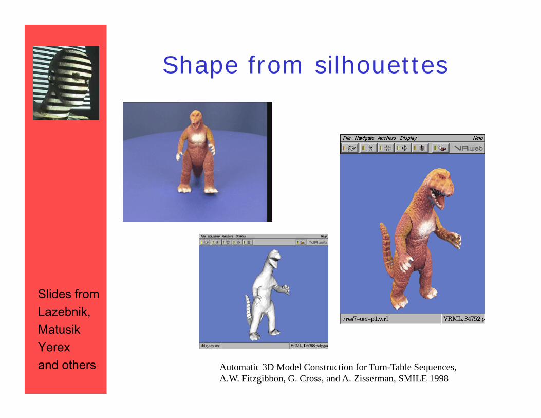
Shape from silhouettes
Automatic 3D Model Construction for Turn-Table Sequences, A.W. Fitzgibbon, G. Cross, and A. Zisserman, SMILE 1998
Slides fromLazebnik,MatusikYerexand others
Big Picture
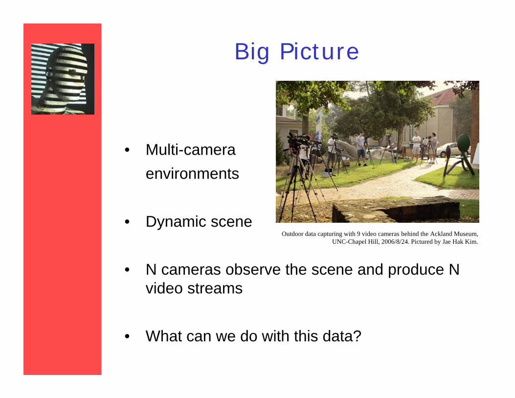
• Multi-camera environments
• Dynamic scene
• N cameras observe the scene and produce N video streams
• What can we do with this data?
Outdoor data capturing with 9 video cameras behind the Ackland Museum, UNC-Chapel Hill, 2006/8/24. Pictured by Jae Hak Kim.
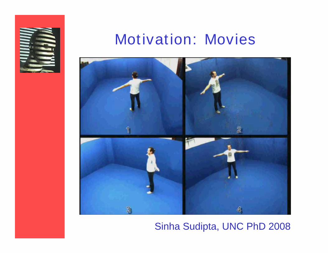
Motivation: Movies
Sinha Sudipta, UNC PhD 2008
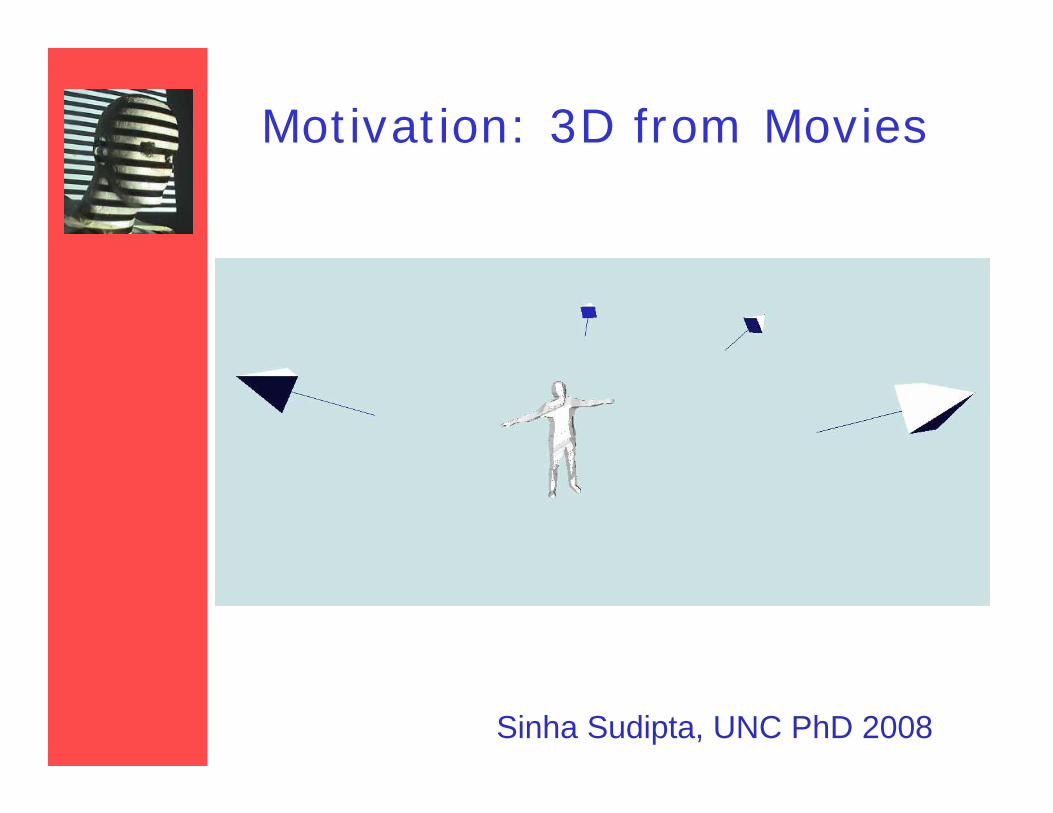
Motivation: 3D from Movies
Sinha Sudipta, UNC PhD 2008
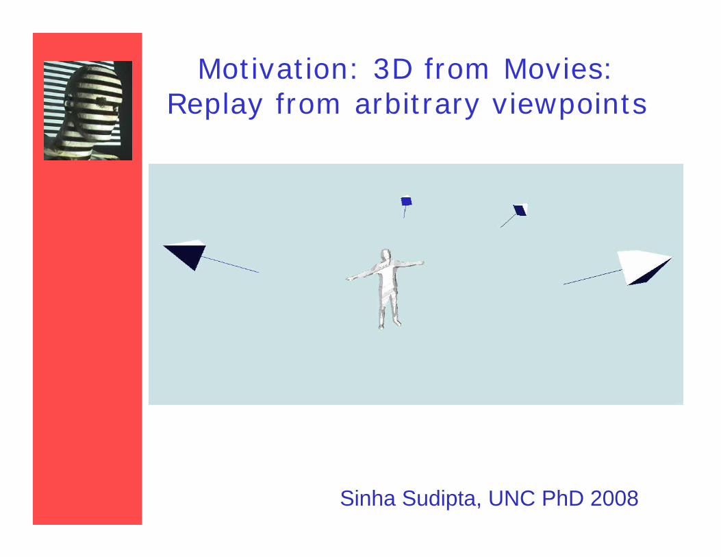
Motivation: 3D from Movies:Replay from arbitrary viewpoints
Sinha Sudipta, UNC PhD 2008
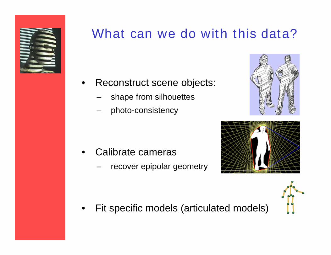
What can we do with this data?
• Reconstruct scene objects:– shape from silhouettes– photo-consistency
• Calibrate cameras– recover epipolar geometry
• Fit specific models (articulated models)
Outline
• Silhouettes– basic concepts– extract silhouettes– fundamentals about using silhouettes– reconstruct shapes from silhouettes– use uncertain silhouettes– calibrate from silhouettes
• Perspectives and interesting ideas
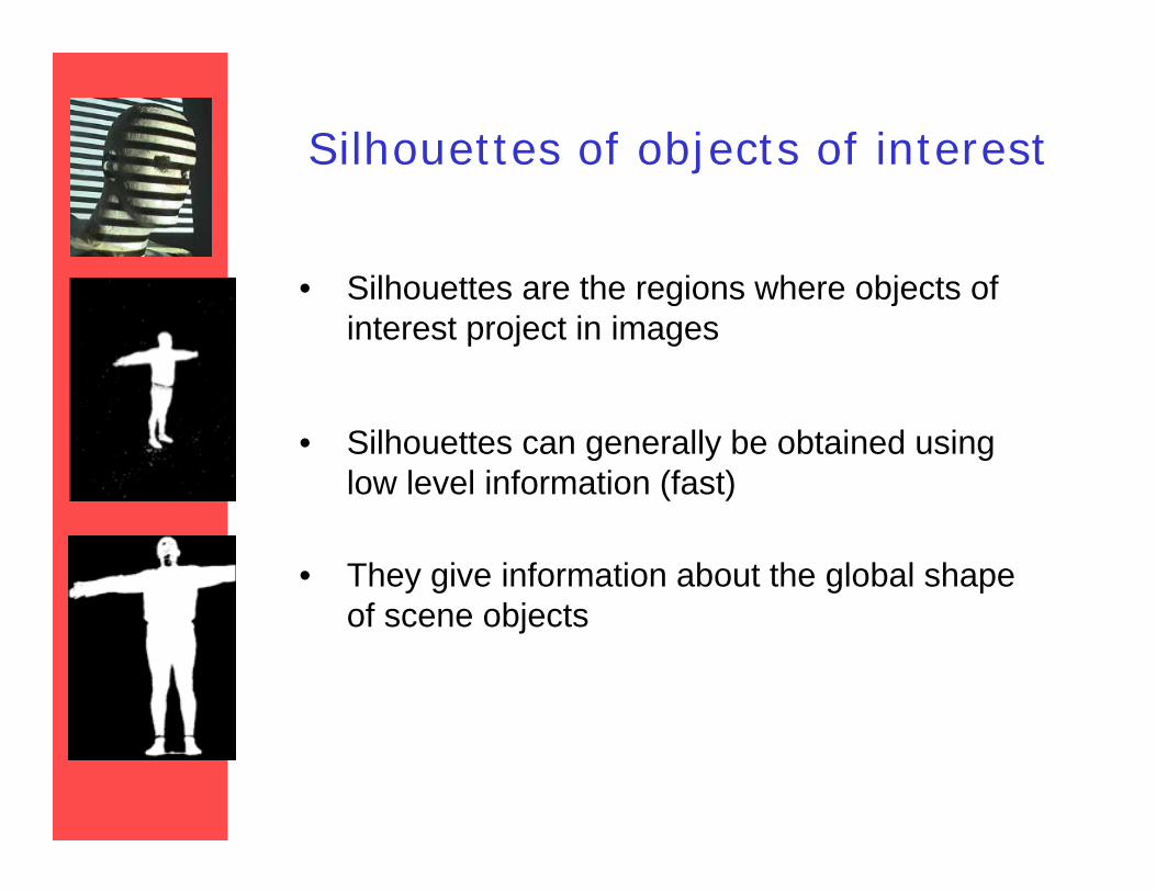
Silhouettes of objects of interest
• Silhouettes are the regions where objects of interest project in images
• Silhouettes can generally be obtained using low level information (fast)
• They give information about the global shape of scene objects
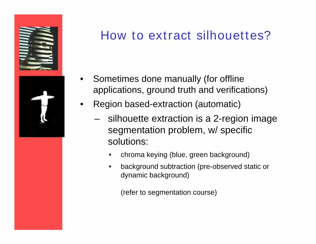
How to extract silhouettes?
• Sometimes done manually (for offline applications, ground truth and verifications)
• Region based-extraction (automatic)– silhouette extraction is a 2-region image
segmentation problem, w/ specific solutions:• chroma keying (blue, green background)• background subtraction (pre-observed static or
dynamic background)
(refer to segmentation course)
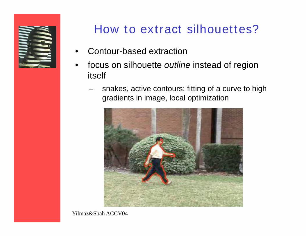
How to extract silhouettes?
• Contour-based extraction• focus on silhouette outline instead of region
itself– snakes, active contours: fitting of a curve to high
gradients in image, local optimization
Yilmaz&Shah ACCV04
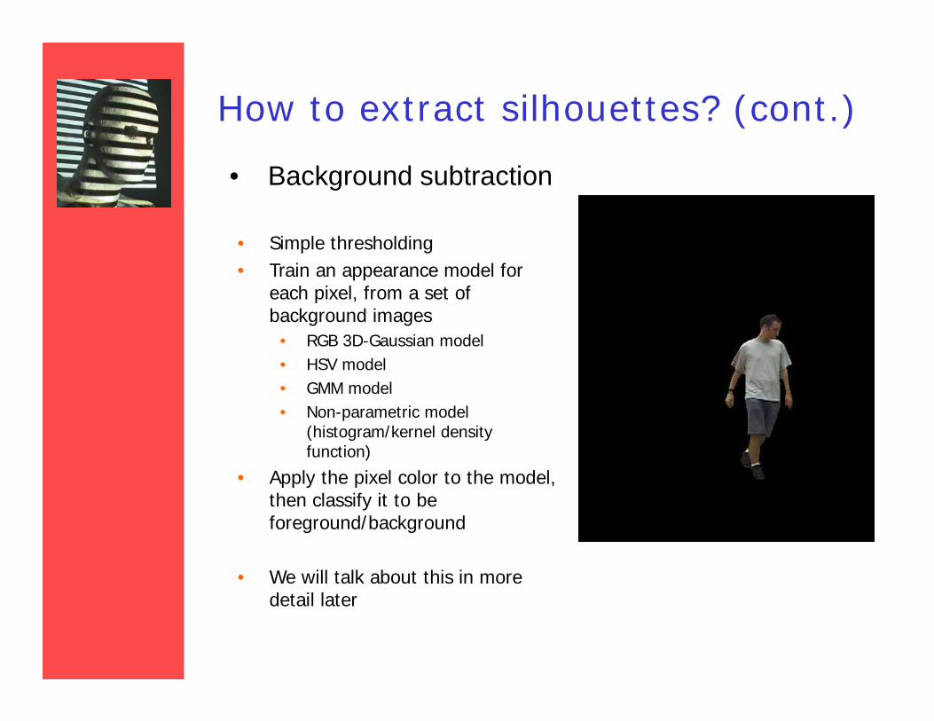
How to extract silhouettes? (cont.)
• Background subtraction
• Simple thresholding• Train an appearance model for
each pixel, from a set of background images
• RGB 3D-Gaussian model• HSV model• GMM model• Non-parametric model
(histogram/kernel density function)
• Apply the pixel color to the model, then classify it to be foreground/background
• We will talk about this in more detail later
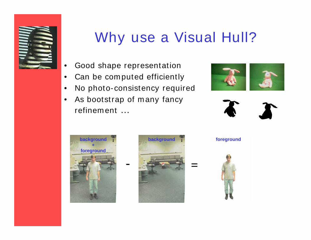
Why use a Visual Hull?
• Good shape representation• Can be computed efficiently• No photo-consistency required• As bootstrap of many fancy
refinement …
- =
background +
foreground
background foreground
Outline
• Silhouettes– basic concepts– extract silhouettes– fundamentals about using silhouettes– reconstruct shapes from silhouettes– use uncertain silhouettes– calibrate from silhouettes
• Perspectives and cool ideas
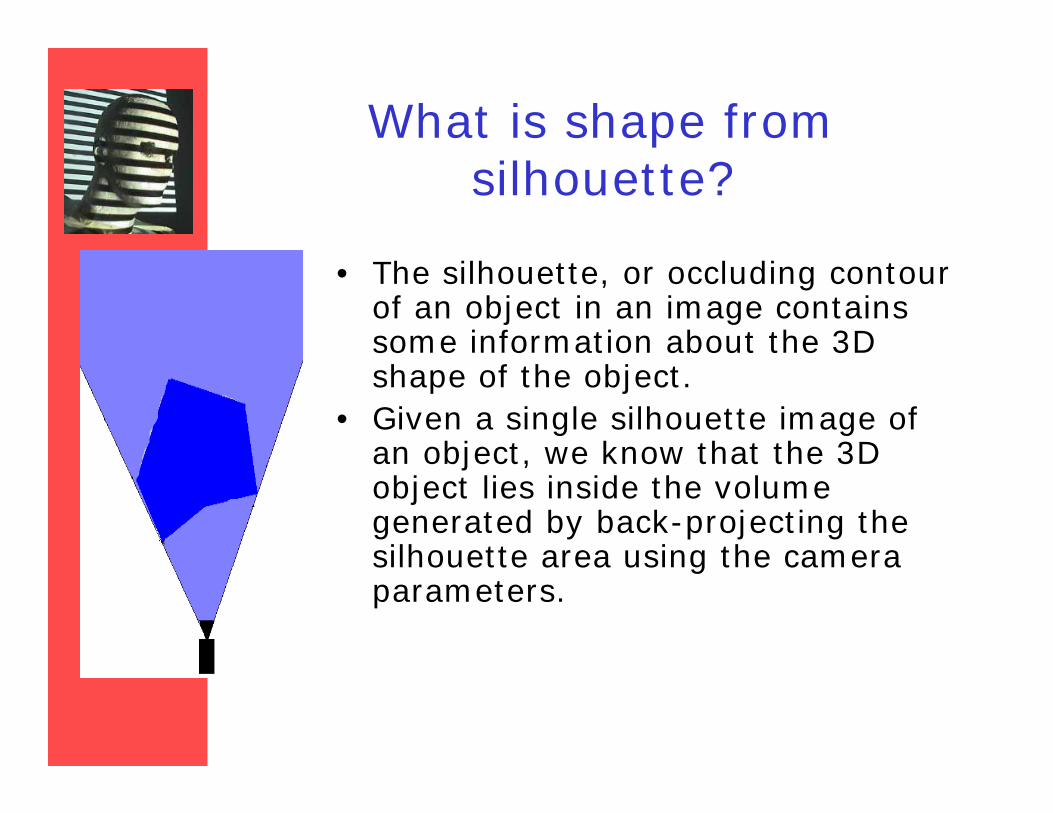
What is shape from silhouette?
• The silhouette, or occluding contour of an object in an image contains some information about the 3D shape of the object.
• Given a single silhouette image of an object, we know that the 3D object lies inside the volume generated by back-projecting the silhouette area using the camera parameters.
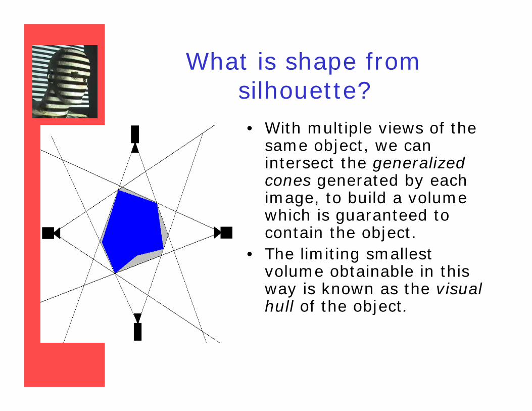
What is shape from silhouette?• With multiple views of the
same object, we can intersect the generalized cones generated by each image, to build a volume which is guaranteed to contain the object.
• The limiting smallest volume obtainable in this way is known as the visual hull of the object.
Literature
• Theory – Laurentini ’94, Petitjean ’98, Laurentini ’99
• Solid cone intersection:– Baumgart ’74 (polyhedra), Szeliski ’93 (octrees)
• Image-based visual hulls– Matusik et al. ’00, Matusik et al. ’01
• Advanced modeling– Sullivan & Ponce ’98, Cross & Zisserman ’00,
Matusik et al. ’02• Applications
– Leibe et al. ’00, Lok ’01, Shlyakhter et al. ’01
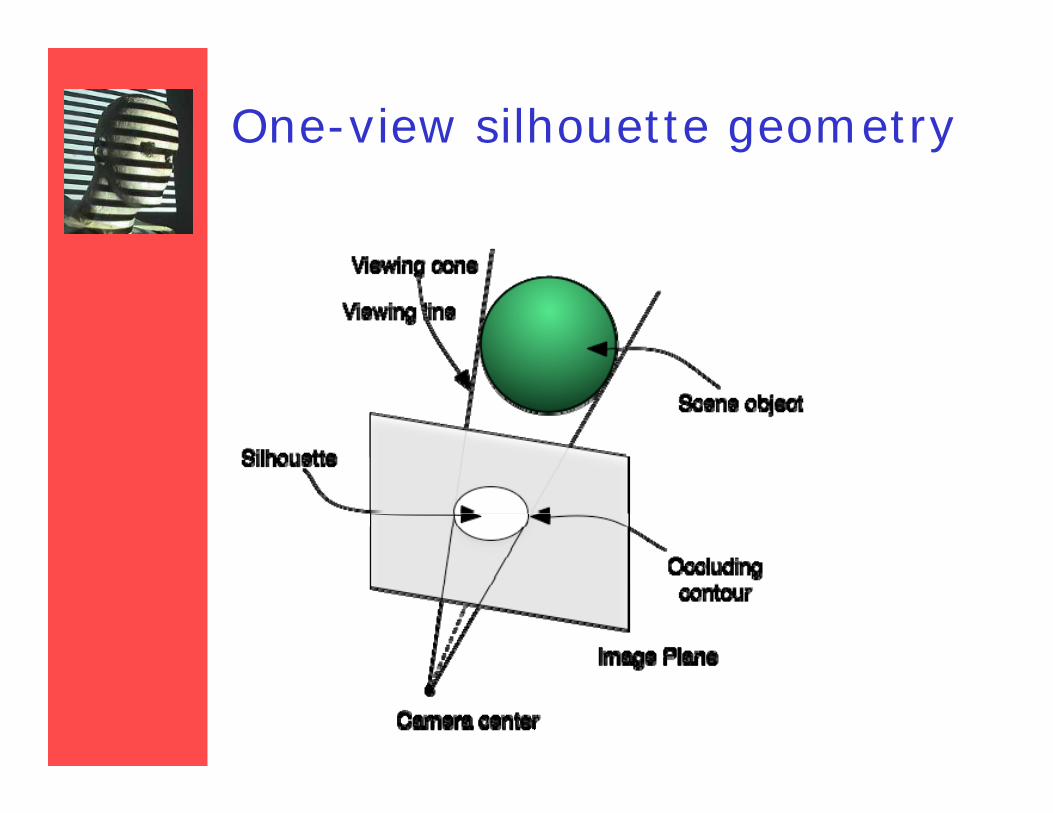
One-view silhouette geometry
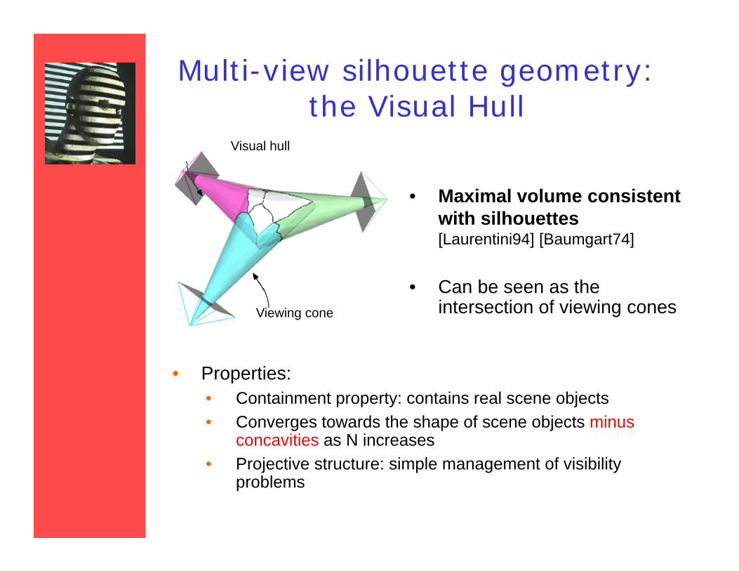
Multi-view silhouette geometry: the Visual Hull
• Maximal volume consistent with silhouettes[Laurentini94] [Baumgart74]
• Can be seen as the intersection of viewing cones
Visual hull
Viewing cone
• Properties:• Containment property: contains real scene objects• Converges towards the shape of scene objects minus
concavities as N increases• Projective structure: simple management of visibility
problems
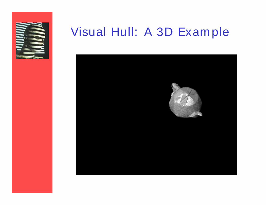
Visual Hull: A 3D Example
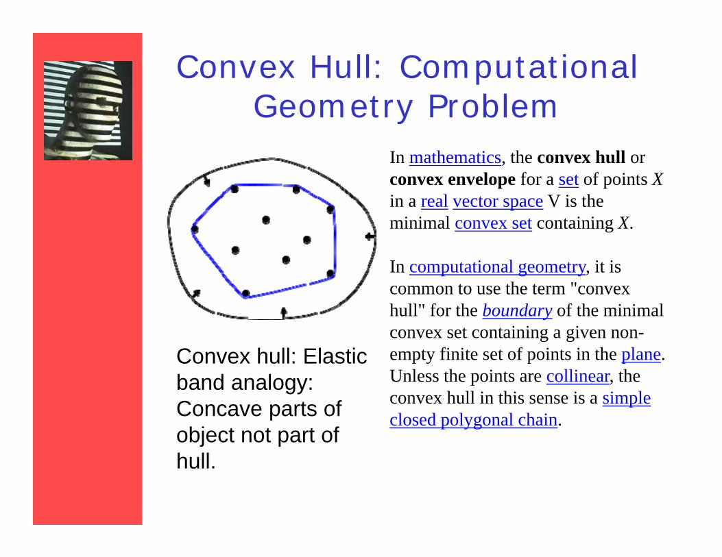
Convex Hull: Computational Geometry Problem
Convex hull: Elastic band analogy: Concave parts of object not part of hull.
In mathematics, the convex hull or convex envelope for a set of points Xin a real vector space V is the minimal convex set containing X.
In computational geometry, it is common to use the term "convex hull" for the boundary of the minimal convex set containing a given non-empty finite set of points in the plane. Unless the points are collinear, the convex hull in this sense is a simple closed polygonal chain.
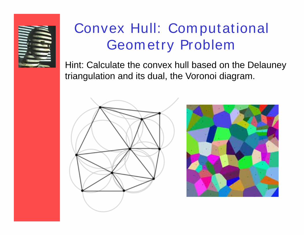
Convex Hull: Computational Geometry Problem
Hint: Calculate the convex hull based on the Delauney triangulation and its dual, the Voronoi diagram.
Outline
• Silhouettes– basic concepts– extract silhouettes– fundamentals about using silhouettes– reconstruct shapes from silhouettes– use uncertain silhouettes– calibrate from silhouettes
• Perspectives and cool ideas
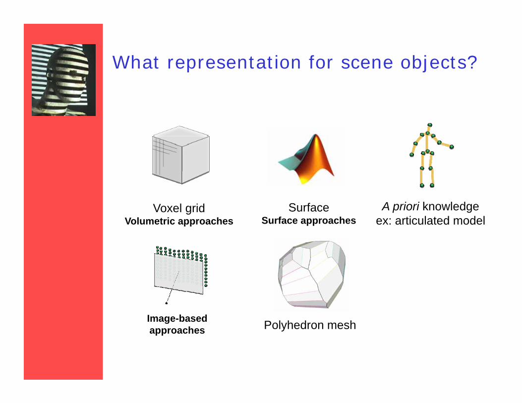
What representation for scene objects?
Voxel gridVolumetric approaches
SurfaceSurface approaches
A priori knowledgeex: articulated model
Polyhedron meshImage-basedapproaches

General idea and assumptions
• 2 main families of approaches for VH:– focus on visual hull as volume: locate portions of
space that don't project in silhouettes (carving)• use 2D silhouette regions in images
– focus on visual hull as surface: locate the boundary surface of the visual hull
• use 2D silhouette contours in images
• General assumptions:– very good silhouettes are extracted– views are calibrated
• parameters and positions are known
Computational complexity
• Intersection of many volumes can be slow• Simple polyhedron-polyhedron intersection
algorithms are inefficient
• To improve performance, most methods:– Quantize volumesand/or– Perform Intersection computations in 2D not 3D
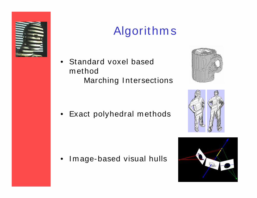
Algorithms
• Standard voxel based method
Marching Intersections
• Exact polyhedral methods
• Image-based visual hulls
Voxel based
– First the object space is split up into a 3D grid of voxels.
– Each voxel is intersected with each silhouette volume.
– Only voxels that lie inside all silhouette volumes remain part of the final shape.
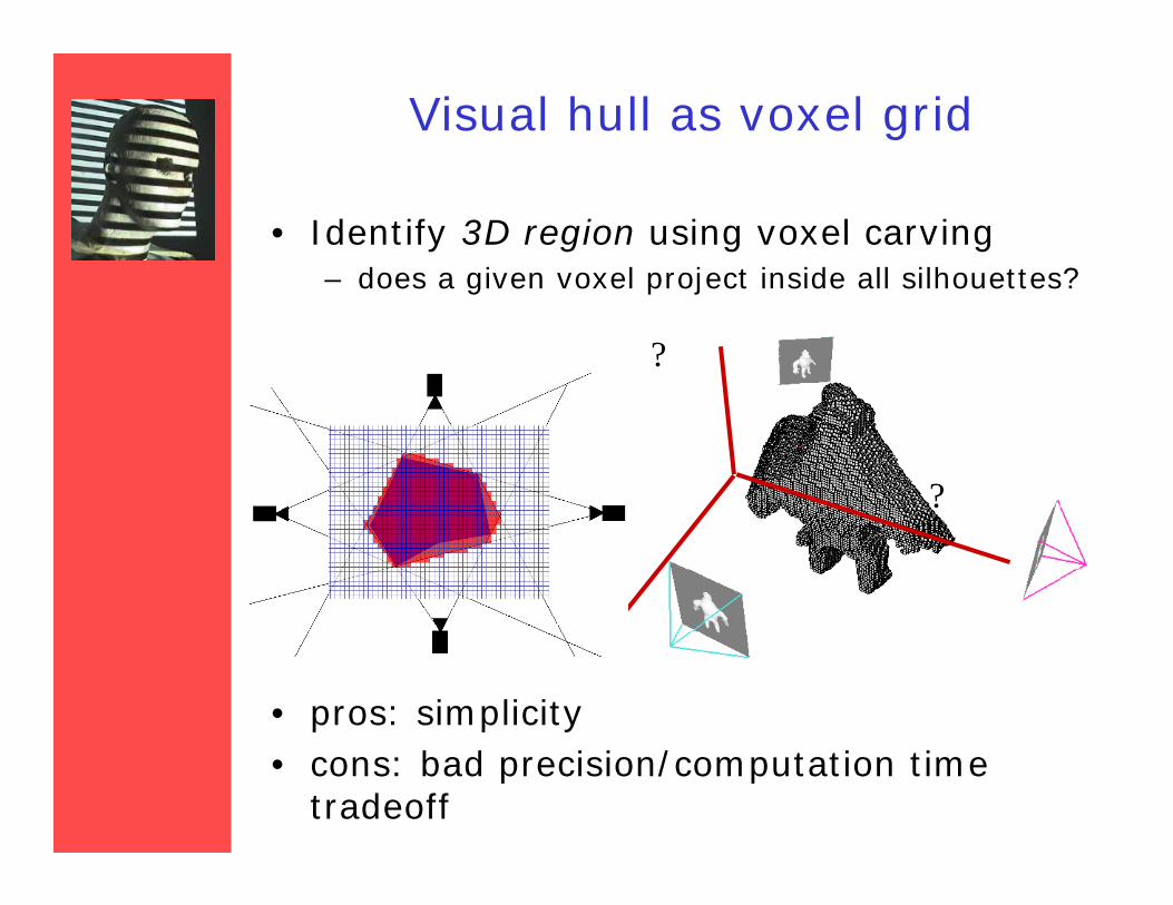
Visual hull as voxel grid
• Identify 3D region using voxel carving– does a given voxel project inside all silhouettes?
• pros: simplicity• cons: bad precision/computation time
tradeoff
?
??
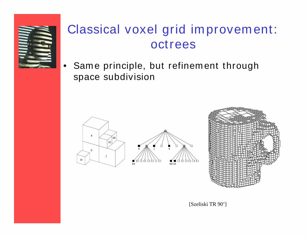
Classical voxel grid improvement: octrees
• Same principle, but refinement through space subdivision
[Szeliski TR 90’]
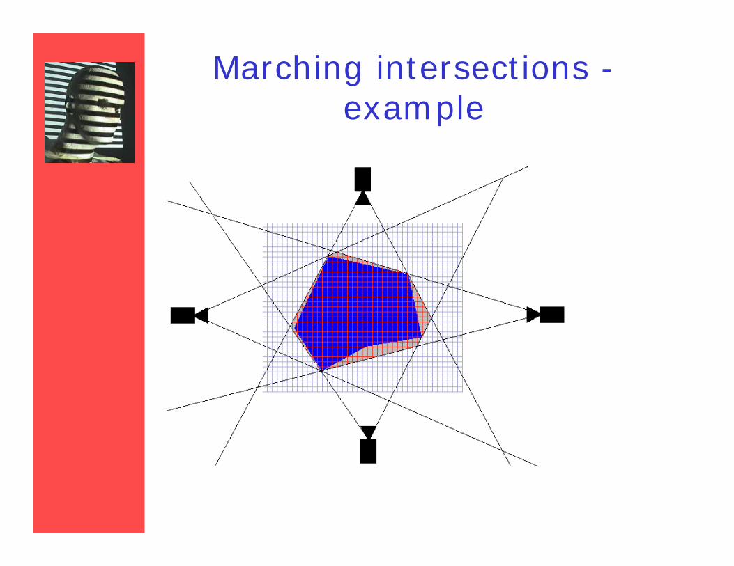
Marching intersectionsTarini et al., 2002
– The object space is again split up into a 3D grid.– The grid used is made of 3 sets of rays, rather than
voxels.– Rays are aligned with the 3 axes, and store points of
entry/exit into the volume– Each silhouette cone can be converted to the
marching intersections data structure.– Then merging them is reduced to 1D intersections
along each ray.
M. Tarini et al, Marching intersections, An efficient Approach to Shape from Silhouette
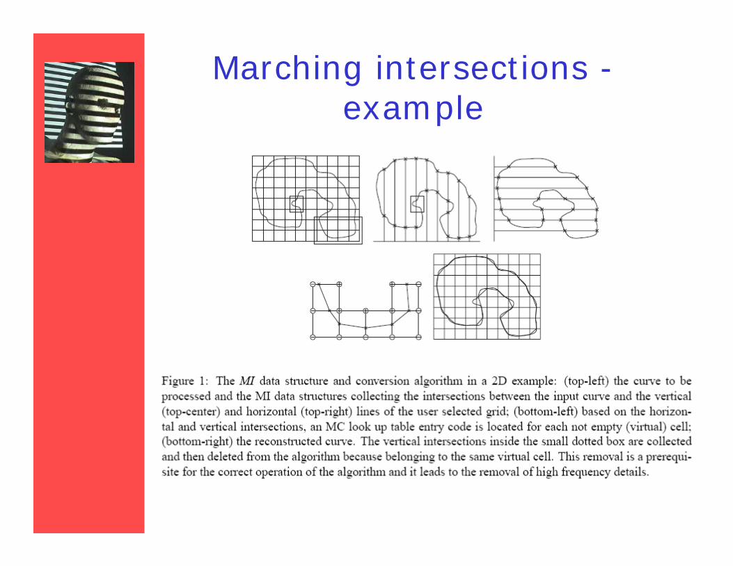
Marching intersections -example
Marching intersections -example
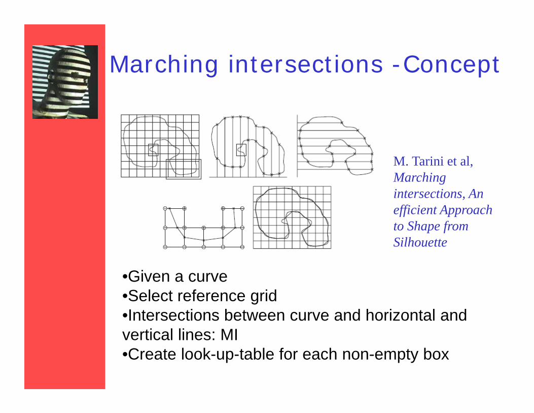
Marching intersections -Concept
•Given a curve•Select reference grid•Intersections between curve and horizontal and vertical lines: MI•Create look-up-table for each non-empty box
M. Tarini et al, Marching intersections, An efficient Approach to Shape from Silhouette
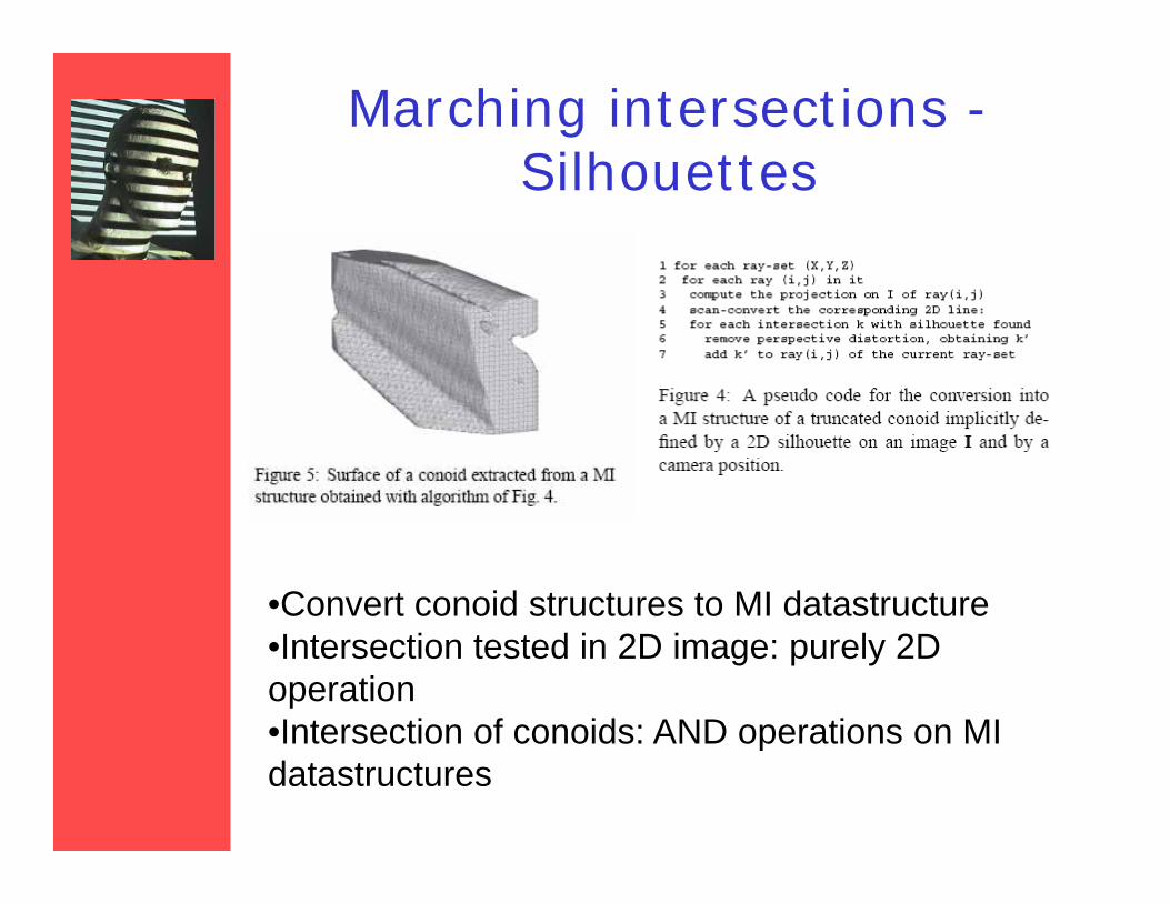
Marching intersections -Silhouettes
•Convert conoid structures to MI datastructure•Intersection tested in 2D image: purely 2D operation•Intersection of conoids: AND operations on MI datastructures
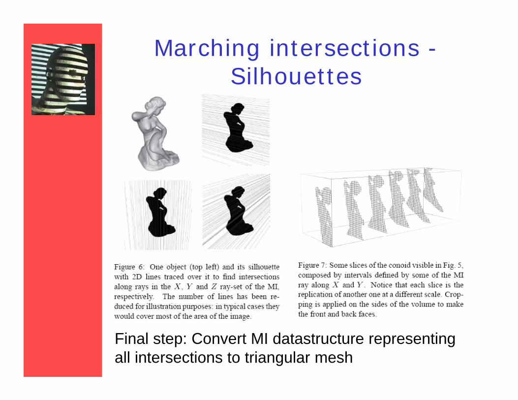
Marching intersections -Silhouettes
Final step: Convert MI datastructure representing all intersections to triangular mesh
Marching intersections -Silhouettes
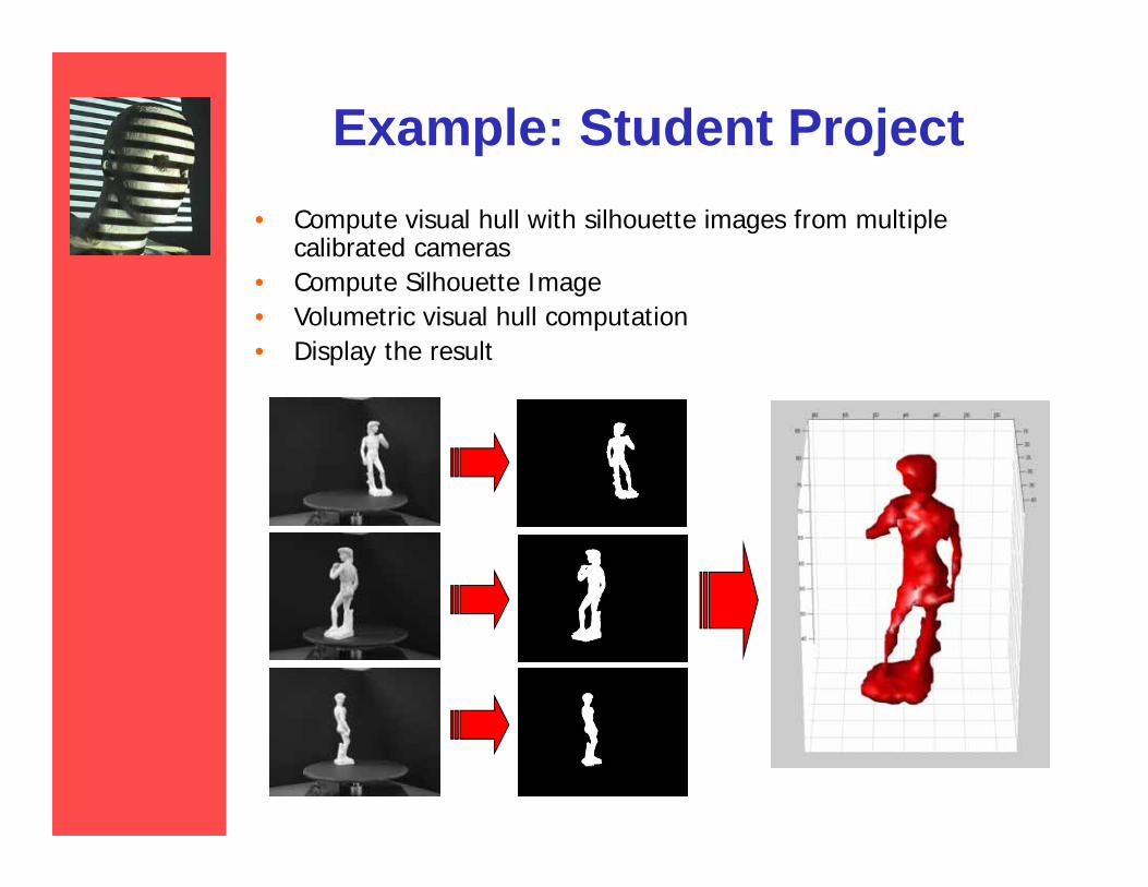
Example: Student Project• Compute visual hull with silhouette images from multiple
calibrated cameras• Compute Silhouette Image • Volumetric visual hull computation• Display the result
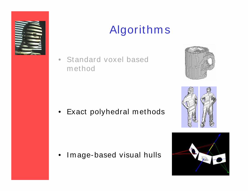
Algorithms
• Standard voxel based method
• Exact polyhedral methods
• Image-based visual hulls
Exact Polyhedral MethodsWojciech Matusik et al.
– First, silhouette images are converted to polygons. (convex or non-convex, with holes allowed)
– Each edge is back projected to form a 3d polygon.
– Then each polygon is projected onto each image, and intersected with each silhouette in 2D.
– The resulting polygons are assembled to form the polyhedral visual hull
Wojciech Matusik, An Efficient Visual Hull Computation Algorithm
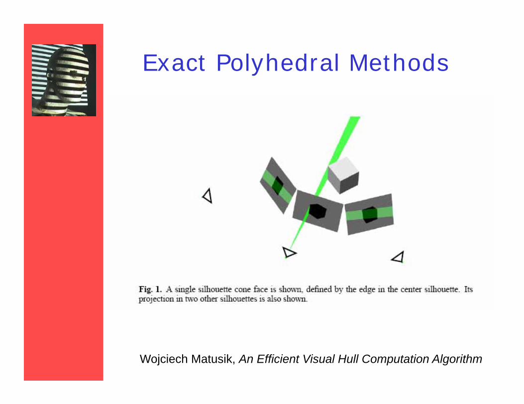
Exact Polyhedral Methods
Wojciech Matusik, An Efficient Visual Hull Computation Algorithm

Exact Polyhedral - example
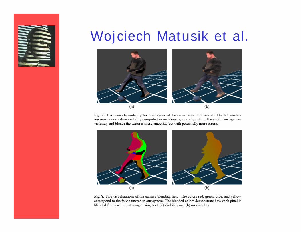
Wojciech Matusik et al.
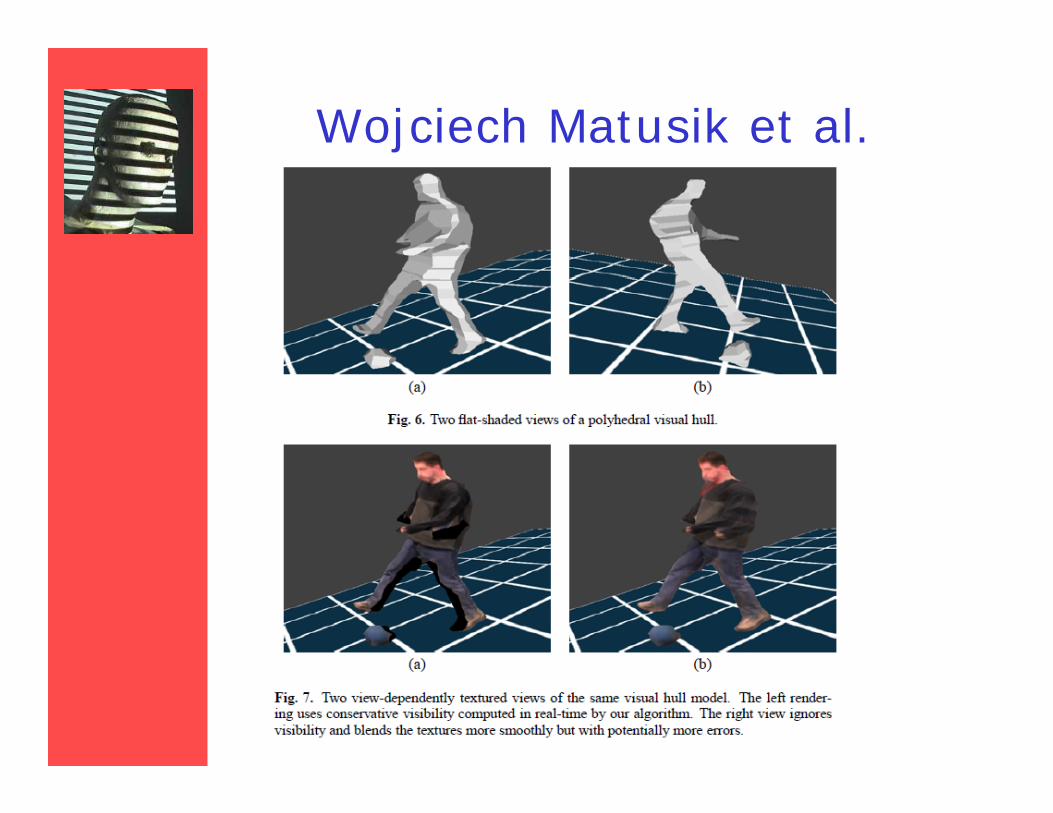
Wojciech Matusik et al.
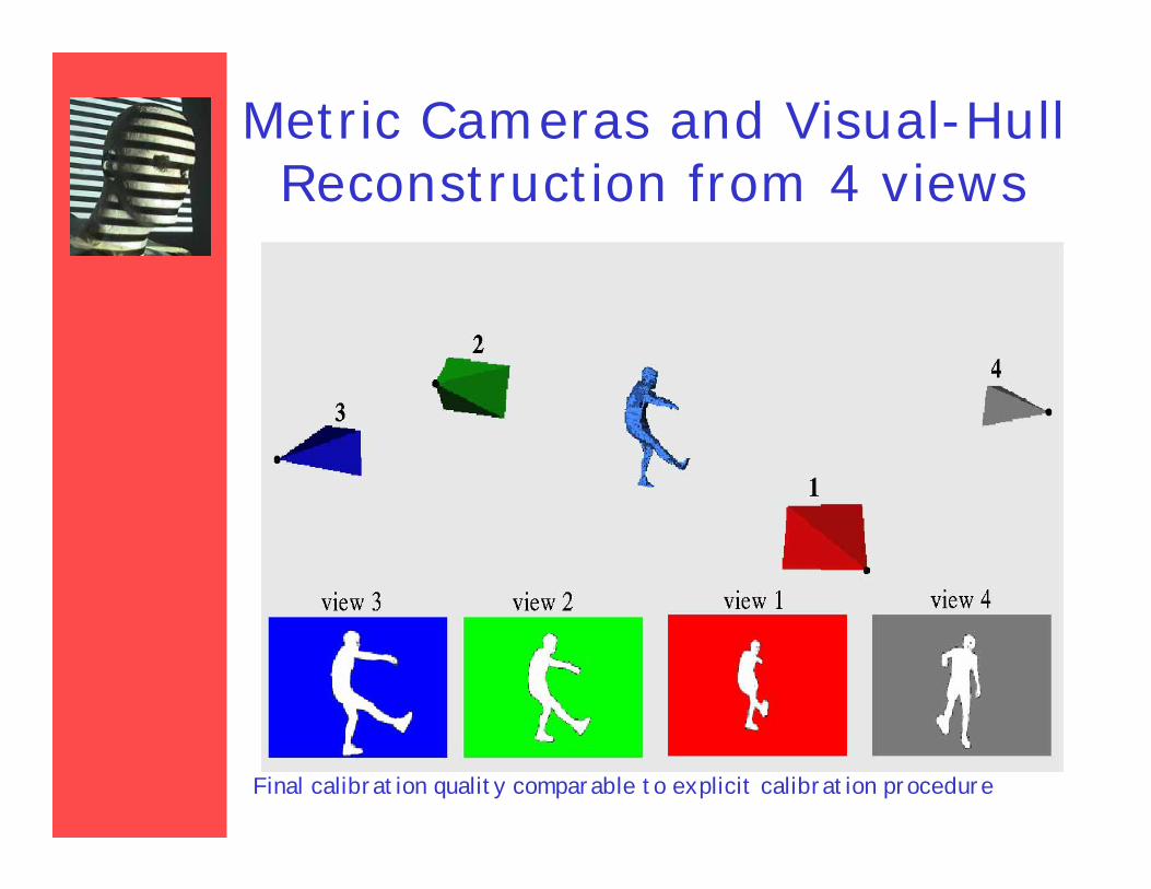
Metric Cameras and Visual-Hull Reconstruction from 4 views
Final calibration quality comparable to explicit calibration procedure
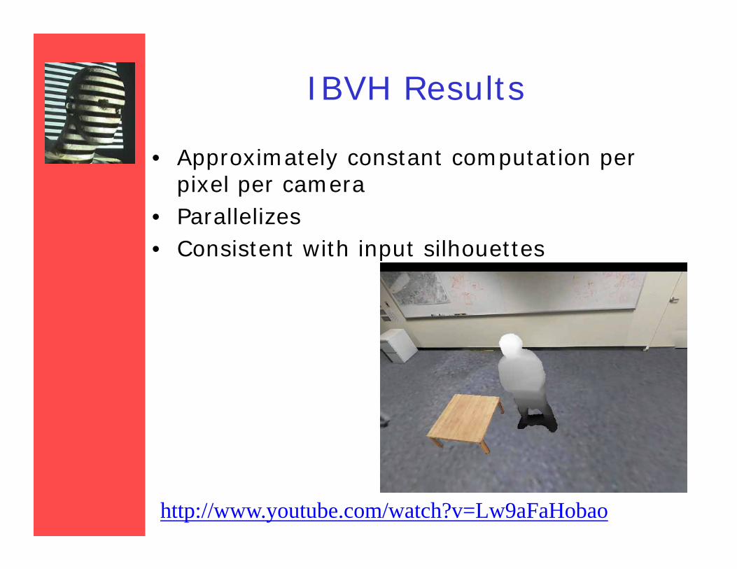
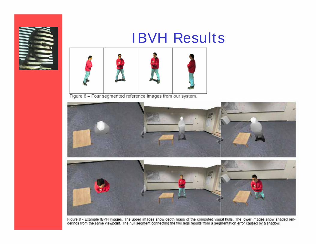
IBVH Results
• Approximately constant computation per pixel per camera
• Parallelizes• Consistent with input silhouettes
http://www.youtube.com/watch?v=Lw9aFaHobao
IBVH Results
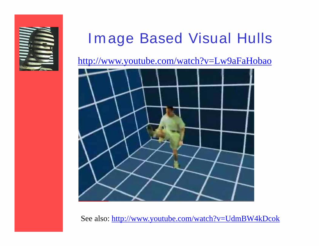
Image Based Visual Hullshttp://www.youtube.com/watch?v=Lw9aFaHobao
See also: http://www.youtube.com/watch?v=UdmBW4kDcok
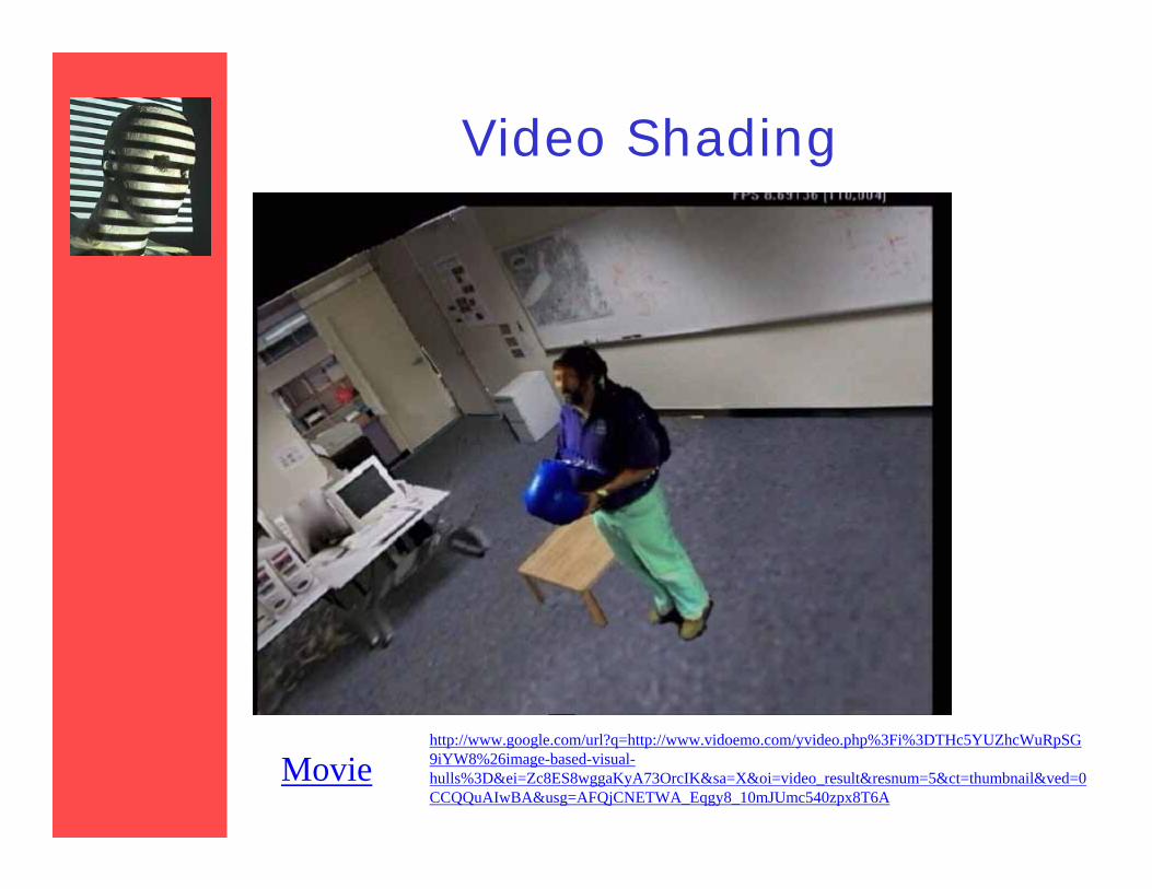
Video Shading
Moviehttp://www.google.com/url?q=http://www.vidoemo.com/yvideo.php%3Fi%3DTHc5YUZhcWuRpSG9iYW8%26image-based-visual-hulls%3D&ei=Zc8ES8wggaKyA73OrcIK&sa=X&oi=video_result&resnum=5&ct=thumbnail&ved=0CCQQuAIwBA&usg=AFQjCNETWA_Eqgy8_10mJUmc540zpx8T6A