Structural Response of Composite Beams
28
Compmifes Engineering, Vol. 2. Nos 5-7. pp. 347-374, 1992. Printed in Great Britain. G961-9526/92 $5.&l+ .CfJ 0 1992 Pergamon Press Ltd STRUCTURAL RESPONSE OF COMPOSITE BEAMS AND BLADES WITH ELASTIC COUPLINGS RAMESH CHANDRA and INDERJIT CHOPRA Center for Rotorcraft Education and Research, Department of Aerospace Engineering, University of Maryland, College Park, MD 20742, U.S.A. (Received 29 January 1992; final version accepted 20 February 1992) Abstract-The structural behavior of coupled, thin-walled, composite beams of open as well as closed section was analyzed using Vlasov theory and then the results were validated by experiment. The analysis modeled the walls of beams as general composite laminates and accounted for the transverse shear deformation of the cross-section. The out-of-plane warping deformation of the cross-section was included implicitly in this formulation. In order to validate the analysis, graphite-epoxy beams of various cross-sections such as solid rectangular, I-section, single-cell rectangular and two-cell airfoil were fabricated and tested for their structural response under tip bending, torsional and extensional loads. Specialized bending-torsion and extension-torsion couplings were introduced in these beams using proper ply lay-ups. Good correlation between theoretical and experimental results was achieved. Transverse-shear-related couplings were found to influence the structural response of open- as well as closed-section beams. For blades with hygrothermally stable lay-ups, bending-transverse shear coupling increased the bending flexibility by about 50%. The in-plane-bending coupling stiffness [B] of the walls of the beam generally influenced the structural response of the beams quite significantly; this effect was expecially large for I-beams. The influence of constraining the warping deformation was found to be substantial on the structural response of open-section beams as compared to closed-section beams. A 630% increase in the torsional stiffness due to constrained warping was noticed for graphite-epoxy I-beams of slenderness ratio 30. The feasibility of achieving the desired levels of bending-torsion and extension-torsion couplings in two-cell rotor blades was demonstrated. NOTATION chord and thickness of two-cell composite rotor blade length of beam coordinate system for plate segment coordinate system for beam displacements in the n, s, z directions, referring to the plate segment displacements in the x, y, z directions, referring to the beam membrane strains referring to the plate segment bending curvature referring to the plate segment rotations about the x, y, z axes, referring to the beam transverse shear strains for the beam in the xz and yz planes, respectively warping function constrained warping parameter stress field referring to the plate segment stress resultants referring to the plate segment moment results referring to the plate segment axial force referring to the beam bending moments referring to the beam shear forces in the x, y directions, referring to the beam torsion moment referring to the beam bimoment (or warping moment) referring to the beam stiffness matrix for the beam applied torsion at the tip of the beam applied force at the tip of the beam axial force at the tip of the beam Young’s moduli of the plies in the principal directions Poisson’s ratio of the plies in the principal plane shear modulus of the plies in the principal plane differentiation with respect to the z coordinate of the beam INTRODUCTION Composite beams of open as well as closed sections form important structural elements of aerospace systems, such as helicopter rotor blades and airplane wings. Although composite COE 2:5/7-o 347
-
Upload
ramprasad-srinivasan -
Category
Documents
-
view
253 -
download
0
description
Composite Beams Used for Blade Modeling
Transcript of Structural Response of Composite Beams

Compmifes Engineering, Vol. 2. Nos 5-7. pp. 347-374, 1992. Printed in Great Britain.
G961-9526/92 $5.&l+ .CfJ 0 1992 Pergamon Press Ltd
STRUCTURAL RESPONSE OF COMPOSITE BEAMS AND BLADES WITH ELASTIC COUPLINGS
RAMESH CHANDRA and INDERJIT CHOPRA Center for Rotorcraft Education and Research, Department of Aerospace Engineering,
University of Maryland, College Park, MD 20742, U.S.A.
(Received 29 January 1992; final version accepted 20 February 1992)
Abstract-The structural behavior of coupled, thin-walled, composite beams of open as well as closed section was analyzed using Vlasov theory and then the results were validated by experiment. The analysis modeled the walls of beams as general composite laminates and accounted for the transverse shear deformation of the cross-section. The out-of-plane warping deformation of the cross-section was included implicitly in this formulation. In order to validate the analysis, graphite-epoxy beams of various cross-sections such as solid rectangular, I-section, single-cell rectangular and two-cell airfoil were fabricated and tested for their structural response under tip bending, torsional and extensional loads. Specialized bending-torsion and extension-torsion couplings were introduced in these beams using proper ply lay-ups. Good correlation between theoretical and experimental results was achieved. Transverse-shear-related couplings were found to influence the structural response of open- as well as closed-section beams. For blades with hygrothermally stable lay-ups, bending-transverse shear coupling increased the bending flexibility by about 50%. The in-plane-bending coupling stiffness [B] of the walls of the beam generally influenced the structural response of the beams quite significantly; this effect was expecially large for I-beams. The influence of constraining the warping deformation was found to be substantial on the structural response of open-section beams as compared to closed-section beams. A 630% increase in the torsional stiffness due to constrained warping was noticed for graphite-epoxy I-beams of slenderness ratio 30. The feasibility of achieving the desired levels of bending-torsion and extension-torsion couplings in two-cell rotor blades was demonstrated.
NOTATION
chord and thickness of two-cell composite rotor blade length of beam coordinate system for plate segment coordinate system for beam displacements in the n, s, z directions, referring to the plate segment displacements in the x, y, z directions, referring to the beam membrane strains referring to the plate segment bending curvature referring to the plate segment rotations about the x, y, z axes, referring to the beam transverse shear strains for the beam in the xz and yz planes, respectively warping function constrained warping parameter stress field referring to the plate segment stress resultants referring to the plate segment moment results referring to the plate segment axial force referring to the beam bending moments referring to the beam shear forces in the x, y directions, referring to the beam torsion moment referring to the beam bimoment (or warping moment) referring to the beam stiffness matrix for the beam applied torsion at the tip of the beam applied force at the tip of the beam axial force at the tip of the beam Young’s moduli of the plies in the principal directions Poisson’s ratio of the plies in the principal plane shear modulus of the plies in the principal plane differentiation with respect to the z coordinate of the beam
INTRODUCTION
Composite beams of open as well as closed sections form important structural elements of aerospace systems, such as helicopter rotor blades and airplane wings. Although composite
COE 2:5/7-o 347
348 R. CHANDRA and I. CHOPRA
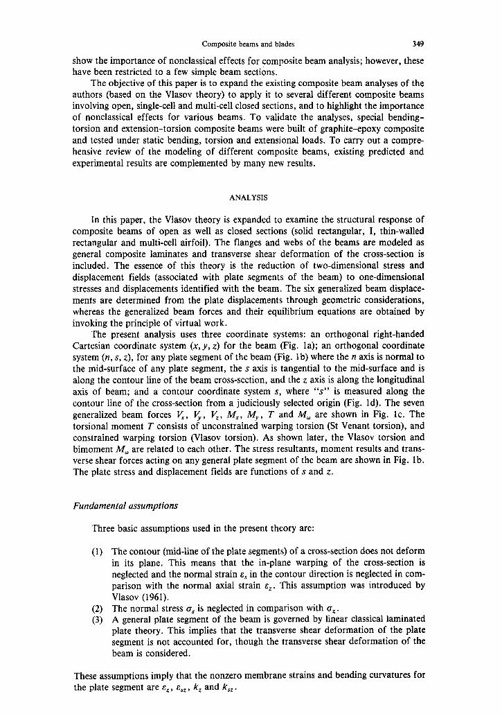
materials have been used by the aerospace industry for several years, bending-torsion and extension-torsion couplings due to laminated composite have not been exploited at this time to improve the aeroelastic characteristics of these systems. For this, it is necessary to develop a simple, accurate model of composite beams which can be incorporated into comprehensive aeroelastic analyses. It is now well established that nonclassical effects, such as cross-section warping, transverse shear and warping constraint at the fixed end, become important for the analysis of composite beams and therefore must be addressed in the modeling of composite beams.
In order to study the aeroelastic stability of hingeless rotor blades, Hong and Chopra (1985) developed a simple analysis for composite box beams with elastic couplings. That analysis was based upon a solid-section approach similar to that used by Hodges and Dowel1 (1974) for isotropic blades. Chandra et al. (1990) evaluated this structural model using a detailed finite element analysis as well as experimental techniques, and identified certain limitations. Smith and Chopra (1991) improved the model by introducing trans- verse shear deformation of the cross-section, a refined section warping and proper in- plane elasticity. Chandra and Chopra (1992) used the improved model to predict the free vibration characteristics of rotating box beams and satisfactorily correlated the calculated results with experimental data obtained using an in wcuo rotor test facility.
Rehfield et al. (1990) formulated a composite beam theory for closed sections where transverse shear deformation of the cross-section and constrained warping effects were included. The local bending stiffness of the beam wall was, however, neglected. The analysis was applied to extension-torsion coupled beams and a significant influence of bending-transverse shear coupling on the static structural response of cantilevered beams was shown. Hodges et al. (1991) used that analysis to predict the free vibration character- istics of nonrotating beams. Further, Rehfield et al. (1988) extended their formulation to include multi-cell composite beams. Shear-flow calculations were based on an approach very similar to that described by Megson (1974). The predictions of the static structural response of two-cell composite beams were correlated with finite element results.
Kosmatka (1991) used an elasticity approach to investigate the influence of initial twist on the structural behavior of composite beams. Single-cell D-section beams with initial twist were analyzed. The importance of initial twist in the modeling of rotor blades was highlighted. Bauchau (1987) presented a large-deflection finite element analysis of curved and twisted composite beams. The analysis included transverse-shear- and torsion- related warping. Giavotto et al. (1983) presented a finite element analysis for anisotropic beams. Borri (1986) formulated a composite beam theory from a virtual work approach, where large rotations and accurate cross-sectional warping were included. Minguet and Dugundji (1990a, b) presented an analytical-experimental study of solid-section compo- site beams undergoing arbitrarily large deformations. Good correlation between theory and experiment was achieved.
Open-section composite beams of different cross-sections like rectangular, I, cruci- form, etc. form structural elements of the flexbeam of bearingless rotors. Chandra and Chopra (1991a, b) developed an analysis for a general open-section composite beam based upon the Vlasov theory (Vlasov, 1961; Gjelsvik, 1981). The analysis was applied to predict the static structural response and free-vibration characteristics of composite I-beams with couplings, and results were validated by experiments. An in vucuo rotor test facility was used to obtain experimental data to validate the free-vibration analysis of these beams under rotation. These studies concluded that the segments of open-section composite beams must be modeled as general composite laminates and contrained warping effects must be included. Rehfield and Atilgan (1989) investigated the buckling of composite open-section beams. Transverse shear deformation of the beam cross-section was included, but the local bending stiffness of the wall was neglected. Chandra and Chopra (1991c, d) expanded the Vlasov theory to analyze multi-cell composite rotor blades with elastic couplings under extension, bending and torsional loads. The predicted structural response was successfully correlated with experimental data. These studies showed the importance of multi-cell analysis, and also the feasibility of achieving a significant degree of bending-torsion and extension-torsion couplings in blades. Most of the above studies
Composite beams and blades 349
show the importance of nonclassical effects for composite beam analysis; however, these have been restricted to a few simple beam sections.
The objective of this paper is to expand the existing composite beam analyses of the authors (based on the Vlasov theory) to apply it to several different composite beams involving open, single-cell and multi-cell closed sections, and to highlight the importance of nonclassical effects for various beams. To validate the analyses, special bending- torsion and extension-torsion composite beams were built of graphite-epoxy composite and tested under static bending, torsion and extensional loads. To carry out a compre- hensive review of the modeling of different composite beams, existing predicted and experimental results are complemented by many new results.
ANALYSIS
In this paper, the Vlasov theory is expanded to examine the structural response of composite beams of open as well as closed sections (solid rectangular, I, thin-walled rectangular and multi-cell airfoil). The flanges and webs of the beams are modeled as general composite laminates and transverse shear deformation of the cross-section is included. The essence of this theory is the reduction of two-dimensional stress and displacement fields (associated with plate segments of the beam) to one-dimensional stresses and displacements identified with the beam. The six generalized beam displace- ments are determined from the plate displacements through geometric considerations, whereas the generalized beam forces and their equilibrium equations are obtained by invoking the principle of virtual work.
The present analysis uses three coordinate systems: an orthogonal right-handed Cartesian coordinate system (x, y, z) for the beam (Fig. la); an orthogonal coordinate system (n, s, z), for any plate segment of the beam (Fig. lb) where the n axis is normal to the mid-surface of any plate segment, the s axis is tangential to the mid-surface and is along the contour line of the beam cross-section, and the z axis is along the longitudinal axis of beam; and a contour coordinate system s, where “s” is measured along the contour line of the cross-section from a judiciously selected origin (Fig. Id). The seven generalized beam forces V,, I$, I$, M,, MY, T and h4, are shown in Fig. lc. The torsional moment T consists of unconstrained warping torsion (St Venant torsion), and constrained warping torsion (Vlasov torsion). As shown later, the Vlasov torsion and bimoment M, are related to each other. The stress resultants, moment results and trans- verse shear forces acting on any general plate segment of the beam are shown in Fig. lb. The plate stress and displacement fields are functions of s and z.
Fundamental assumptions
Three basic assumptions used in the present theory are:
(1) The contour (mid-line of the plate segments) of a cross-section does not deform in its plane. This means that the in-plane warping of the cross-section is neglected and the normal strain E, in the contour direction is neglected in com- parison with the normal axial strain E,. This assumption was introduced by Vlasov (1961).
(2) The normal stress o, is neglected in comparison with or. (3) A general plate segment of the beam is governed by linear classical laminated
plate theory. This implies that the transverse shear deformation of the plate segment is not accounted for, though the transverse shear deformation of the beam is considered.
These assumptions imply that the nonzero membrane strains and bending curvatures for the plate segment are E,, cSZ, k, and k,, .

R. CHANDRA and LCHOPRA
Solid Rectangular Section I-Section
Hollow Rectangular Section Two-Cell Airfoil Section
(b)
VY
/J--
VX
VZ.
kf) p t
P,W u
00 Fig. 1. (a) Coordinates of beams. (b) Stress and moment resultants acting on any general plate segment of the beam. (c) Generalized beam forces. (d) Pictorial definitions of blade displacements and rotations.

Kinematics
Composite beams and blades 351
From geometric considerations Fig. Id, the plate displacements u(s, z) and u(s, z) are related to the beam displacement U, V and & as:
u(s, 2) = U(z) sin &s) - V(z) cos O(s) - q(s)&(z) (1)
u(s, z) = U(z) cos O(s) + V(z) sin O(s) + r(s)&(z) (2)
where r, q and 0 are show in Fig. Id. w(s, z) is obtained using the following shear strain-displacement relation:
& sz = w,s + u,,. (3)
The in-plane shear strain E,~ associated with the plate segment consists of two compo- nents; one due to the transverse shear deformation of the cross-section and the other due to torsion. Hence, E,~ is given by:
& s?. = E,, cos e + cyz sin e + E$. (4)
For an open-section beam, the in-plane shear strain due to torsion, E$, is neglected. For a closed-section beam, the in-plane shear strain is calculated from shear flows. It
is further assumed that shear strain esZ @) distribution in the contour direction is similar to that corresponding to the St Venant torsion.
Gjelsvik (1981) showed that E$ is given by:
F(s) controls the variation of this strain along the contour of the beam cross-section. In order to account for variation of shear modulus G along the contour, eqn (5) is rewritten as:
where G,(s) = F(.s)G(s).
G,(s) Eqs z) = - SE 7 Gt 4;(z) (6)
-h, 0
ccc Fig. 2. Schematic of a two-cell blade section.
G,(s) is determined using the compatibility condition for warping deformation (Gjelsvik, 1981). Figure 2 shows a two-cell blade section. It has two circuits for shear flow with five branches. Invoking the condition that the warping deformation over each circuit be zero, the following equation is obtained:
i= 1,2.
Using eqns (2), (3) and (4) in eqn (7),
9 ~dS=2Ai where Ai = fi r ds.
03)
352 R. CHANDRA and 1. CHOPRA
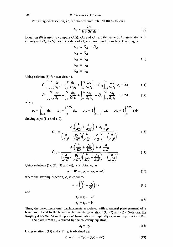
For a single-cell section, G, is obtained from relation (8) as follows:
Equation (8) is used to compute G,(s). Gsl and GS2 are the value of G, associated with circuits and G,r to G,, are the values of G, associated with branches. From Fig. 2,
Gsl = csl - es2
Gs2 = %
Gs3 = cs, (10)
Gs4 = &
Using relation (8) for two circuits,
where
s
c 0.3% c 0.35c
a1 = d.5 P2 = & Ar=2 ydx, A2=2 ydx. 0.3sc 0 s 0.3% s 0
Solving eqns (11) and (12),
G2 =
4(-&+~) +A,&
($+-&i)(-&++)-(-j&G
(13)
(14)
Using relations (2), (3), (4) and (6), w is obtained as:
w = w + xd+ + MJJ - HI (15) where the warping function, p, is equal to:
4, = Exz - U’
f#Jy = Eyz - Y’.
(16)
(17)
Thus, the two-dimensional displacements associated with a general plate segment of a beam are related to the beam displacements by relations (l), (2) and (15). Note that the warping deformation in the present formulation is implicitly expressed by relation (16).
The plate strain E, is related by the following equation:
E, = w,z.
Using relations (15) and (18), E, is obtained as:
E, = W’ + x4; + y#$ + q@;.
(18)
(19)
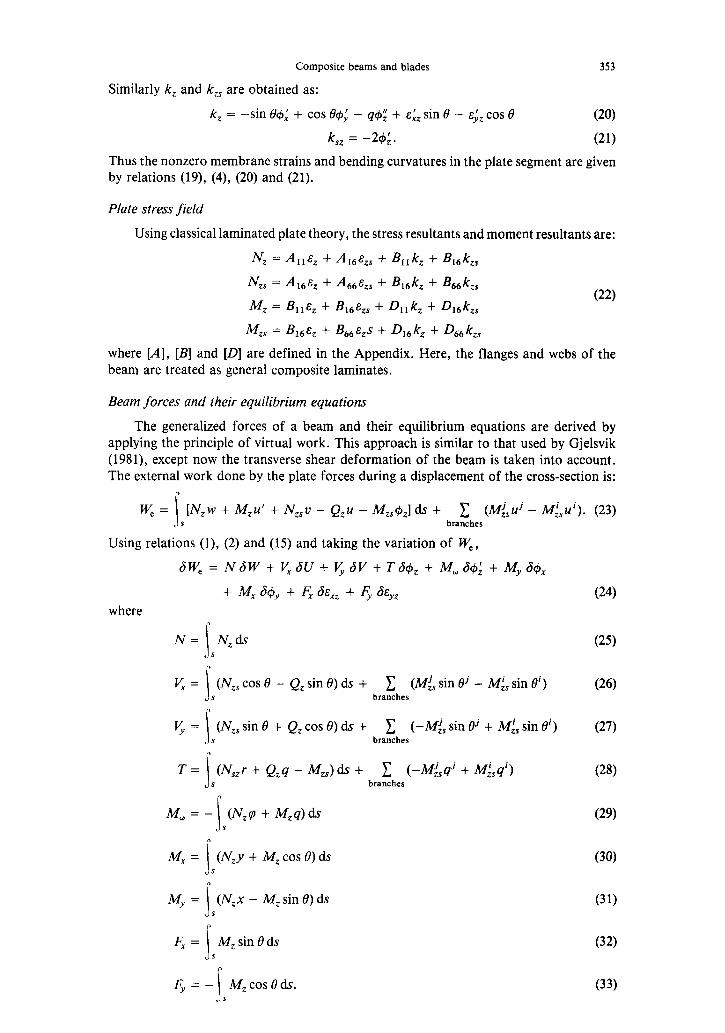
Composite beams and blades 353
Similarly /c, and k,, are obtained as:
k, = -sin f34: + cos 64; - q@ + E.& sin 6’ - ~4, cos 13 (20)
k,, = -26;. (21)
Thus the nonzero membrane strains and bending curvatures in the plate segment are given by relations (19), (4), (20) and (21).
Plate stress field
Using classical laminated plate theory, the stress resultants and moment resultants are:
N, = All&z + -41,~s + B,,k, + B&s
Nzs = Al& + &A, + %k, + B&s
Mz = 41~ + &t&s + D,,kz + h& (22)
Mzs = 46~ + B66w + Q, kz + Q&s
where [A], [B] and [D] are defined in the Appendix. Here, the flanges and webs of the beam are treated as general composite laminates.
Beam forces and their equilibrium equations
The generalized forces of a beam and their equilibrium equations are derived by applying the principle of virtual work. This approach is similar to that used by Gjelsvik (1981), except now the transverse shear deformation of the beam is taken into account. The external work done by the plate forces during a displacement of the cross-section is:
w, = c Wzw + M$” + Nzsu - Qzu - M&J,] ds + c (M$? - A&u'). (23) JS branches
Using relations (l), (2) and (15) and taking the variation of W,,
SW, = N6W + v, 6U + v, 6V + T&, + Mu SC$; + M-,, i&5,
+ M, 6#y + F, &,, + Fy SE,, where
N= N,ds s s
V, = s
(N,, cos ~3 - Q, sin 0) ds + c (i’& sin 13’ - Mi, sin 0’) s branches
V, = s
(Nzs sin 0 + Q, cos 0) ds + c (-M& sin Bj + Ml, sin ai) s branches
T = s
(N,,r + Qzq - M,,)ds + c (-M&qj + MjSqi) s branches
Mw = - (N,Y, + M,q)h s s
Ad, =
s
(N,y + A4, cos e) ds s
My = s
(N,x - Mz sin e) ds s
F, = i
A4, sin B ds s
my = - hf,c0seds. s s
(24)
(25)
(26)
(27)
(28)
(29)
(30)
(31)
(32)
(33)

354 R.CHANDRA and I.CHOPRA
It is difficult to compute the generalized blade forces V,, V, and T from relations (25), (26) and (27) because of the contributions from different branches. These are simpli- fied by using equilibrium equations of plate forces (Gjelsvik, 1981):
<=-My’ (34)
v, = M; (35)
T=T,+T, (36)
where T, is the St Venant torsion (free warping) and T, is Vlasov torsion (constrained warping). These are defined as:
(37)
It is to be noted that the second term in the equation of the St Venant torsion is zero for an open section.
T, = (Nzsr + M;q)ds. (38) s
By using the plate equilibrium equation, relation (37) is simplified to:
T, = -ML. (39
This gives the relationship between the Vlasov torsion and the warping moment (or bimoment).
The external virtual work done by the applied loadings on the plate is:
ndW+ v,dU+ v,dV+ tfJ4, + m,&,” + rn,6& + rn,d& +fx&,, +&BE~~ (40)
where n, v,, v,,, t, m, , my, m,, f, and fY are generalized load intensities on the blade, derived from the loadings on a shell (Gjelsvik, 1981).
The strain energy, l-I, is given as
l-I = + s
(N& + Nzs.szs + M,k, + M,,k,,)ds. s
(41)
Using the relations between the blade forces and shell forces, the strain energy becomes
I-I = $[NW’ + M,$J: + M&J; + T+; + Mad; + F,E:, + Fy& + GxexZ + G,,E,,J. (42)
The internal virtual work, w, is obtained from the strain energy as:
-Y = NW’ + My+: + M,& + T& + Mad; + F,E:, + Z$& + GXcxz + G,,E,,~ (43)
G, = N,,cosOds s
(44 s
G,, = c
N,, sin 0 ds. (45) s
Equilibrium equations for the blade forces are obtained by considering a blade element and equating the external work to the internal work for any virtual displacement. Thus these equations are:
v; + v* = 0 (46)
v,‘+u,=o (47)
N’+n=O (48)
T’+t=O (4%
MA-f-T-T,+m,=O (50)
M; + V, + m,, = 0 (51)
Composite beams and blades 355
M:-~+m,=O (52)
&'-G,+f,=O (53)
l$-G,,ffy=O. (54)
By eliminating V,, V, and T, the equations are reduced to six equations:
N’+n=O (55)
M; + ml; - v, = 0 (56)
M:' + m; + vy = 0 (57)
M: - T,’ + rn: - t’ = 0 (58)
F;-G,+f,=O (5%
Fy)-gy+fy=o. (60)
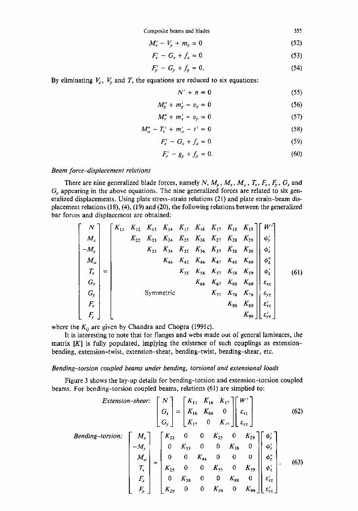
Beam force-displacement relations
There are nine generalized blade forces, namely N, MY, IV,, IV,, T, , F,, 4, G, and G,, appearing in the above equations. The nine generalized forces are related to six gen- eralized displacements. Using plate stress-strain relations (21) and plate strain-beam dis- placement relations (18), (4), (19) and (20), the following relations between the generalized bar forces and displacement are obtained:
N K,, K12 KM KM KIS Kl6 K17 KM K19 W’
Mx K22 K23 K24 K25 K26 K27 K28 K29 6;
-My K33 K34 K35 K36 K37 K38 K3, 6:
Mid K44 K45 K46 K47 K48 K49 6;
T$ = KS, K56 KS, K58 K,, 4: (61)
G K66 &7 &3 Km GZ
GY Symmetric Km K7, Km &yz
F, Ku3 &g &:,
.A- _ 49 _ _ cl, _
where the Kij are given by Chandra and Chopra (1991c). It is interesting to note that for flanges and webs made out of general laminates, the
matrix [K] is fully populated, implying the existence of such couplings as extension- bending, extension-twist, extension-shear, bending-twist, bending-shear, etc.
Bending-torsion coupled beams under bending, torsional and extensional loads
Figure 3 shows the lay-up details for bending-torsion and extension-torsion coupled beams. For bending-torsion coupled beams, relations (61) are simplied to:
Extension-shear:
Bending-torsion: K22 0 0 K25 0 Kzg 0 K33 0 0 K38 0
0 0 K44 0 0 0
= K,, 0 0 K,, 0 K,,
0 K38 0 0 KB8 0
Jz, 0 0 K59 0 K99 _
(62)
. (63)

R.CHANDRA and I.CHOPRA
Bending-Torsion Coupling in Solid Rectangular Cross-Section Beam
Extension-Torsion Coupling in Solid Rectangular Cross-Section Beam
Bending-Torsion Coupling in I-Beam Extension-Torsion Coupling in I-Beam
Bending-Torsion Coupled Beam Extension-Torsion Coupled Beam
Bending-Torsion Coupled Blade Extension-Torsion Coupled Blade
Fig. 3. (a) Lay-up details for coupled composite open-section beams. (b) Lay-up details for coupled composite closed-section beams.
Following the procedure used by Chandra and Chopra (1991a), eqns (62) and (63) are solved to give the bending slope and twist of bending-torsion coupled beams under tip loads.
Tip bending load:
V' = L,,P - &(+,+&)(241z)
K& PI + K,2, WG,),
[coth p(cosh AZ - 1) - sinh AZ]
K25 PI
" = % W&J, coth&cosh AZ - 1) - sinh AZ + & (221 - z2) 1 . (65)
Tip torsional load:
(66)
cash AZ 1 (67)

Composite beams and blades
where
and L,, is given as below:
p=AI= r
(K,,),/ K44
357
(68)
It is to be noted that the influence of direct transverse shear manifests itself in the bending slope relations (65) and (67) through the term L,,.
In order to evaluate the influence of constrained warping on the torsional behavior of these beams, the torsional stiffness is represented as the relative torsional stiffness (RTS) with respect to the St Venant torsional stiffness:
RTS = P ,LI - 2 tanh(p/2) ’ (6%
It is interesting to note that the relative torsional stiffness is controlled by the constrained warping parameter p. This parameter as defined by eqn (68) depends upon the coefficients of ths stiffness matrix and length of the beam. Thus, the influence of geometry and material on the torsional behavior of the beam is felt through this parameter.
Neglecting the constrained warping and direct transverse shear effects, the bending slope and twist relations are simplified to:
Tip bending load:
Tip torsional load:
” = Wn), -At- (212 - 22)
K25 P 4~ = K,, 2K22)r
- (212 - z2).
(70)
(71)
(72)
(73)
where
K225 W22)r = K22 - -
K55 (74)
K22 VMr = KS, - ~22. (75)
Note that for slender beams, the influence of direct transverse shear deformation on the static structural response is negligible. Also for beams where the constrained warping parameter is higher than 40, the constrained warping effects are negligible (Chandra and Chopra, 1991a).
Extension-torsion coupled beams under extensional, torsional and bending loads
For these beams, simplified force-displacement relations are:
Extension-torsion:
(76)
Relations (76) control the extension-torsion coupled behavior of these beams. Note that the extension-torsion coupling is via St Venant torsion.

358 R. CHANDRA and I. CHOPRA
Bending-transverse shear:
(77)
(78)
Relations (77) and (78) control the bending behavior of these beams and the bending- shear couplings are included in these relations.
In the present paper, the structural response of extension-torsion coupled beams is confined to closed section beams. The influence of constrained warping on the structural response of such beams is negligible as the constrained warping parameter is higher than 40 (Chandra and Chopra, 1991a).
Using relations (76), the twist due to the tip torsional load T and induced twist due to the axial force F are given by:
t$z = - K15 K,IKSS - K:,
Fl.
(79)
For beams subjected to a tip bending load P, the rotation $ is obtained from relation (77):
P
” = K,,U - W,2,/K,,K,,)) (81)
From relation (78), eyZ is obtained as:
&YZ = L,,P (82)
where 1
L77 = KT7(1 - (K$,/K,,K,,)) ’
Using relations (Sl), (82) and (17) the bending slope is obtained as:
P ” = L77p - KZ2(1 - (K;6/K22K66))
The first term in relation (84) represents the direct transverse shear effect whereas the second term represents the influence of transverse shear-bending coupling on the bending slope. Note that the bending-shear coupling reduces the bending stiffness. The ratio of the first term to the second term at the tip can be used as a measure of assessing the direct transverse shear effect. This ratio is termed the shear correction factor (SCF) and is given by:
SCF=;L,,K,,(l -&).
The analytical development presented above is generic for open- as well as closed- section composite beams and multi-cell rotor blades. The coefficients of the stiffness matrix [K] are given in a general form. These can easily be specialized for open sections by omitting the shear flow terms. The results in terms of bending slope and twist are also generic.
FABRICATION
To validate the analysis, many different composite beams with specialized couplings were built. These included solid rectangular section beams, thin-walled single-cell box beams, thin-walled open-section I-beams and thin-walled, multi-cell, airfoil-section blades. The solid rectangular-section beams, thin-walled single-cell box beams and

Composite beams and blades 359
Solid Beam
I-Beam
J
Box Beam
Legend:
pJ!j Aluminum Molds
m Composite Lay-up
n Peel Ply
II Porous Bleeder
Bleeder Plies
cl Barrier Film
cl Breather Plies
Rotor Blade
Fig. 4. Details of composite beam fabrication.
I-beams were built using an autoclave molding technique, whereas the two-cell rotor blades were built using a matched-die molding technique.
Solid rectangular-section beams
Figure 4 shows the fabrication details for the solid beam. Metal molds with spacers were used to avoid slipping of plies during curing under pressure. Peel ply was wrapped to provide the surface finish of the beam. In order to bleed out excess resin and to permit the escape of volatiles during the curing process, a number of bleeder and breather layers were then applied. A caul plate was used to facilitate the application of uniform pressure on the laminate. The lay-up was cured in a microprocessor-controlled autoclave according to the curing cycle provided by the manufacturer. Thus, bending-torsion coupled compo- site solid beams with different ply orientations were built.
I-beams
Figure 4 shows the details of fabrication of I-beam specimens. Graphite-epoxy prepreg layers were laid-up on a metal mold which consisted of two parts. Each of these parts would yield beams of channel-section. For the fabrication of I-section beams, each part of the mold was wrapped with the desired number of prepreg layers. These layers were compacted by applying a vacuum between the mold and lay-up. The two parts of the mold were placed back to back and the additional layers were introduced on the top and bottom flanges. Thus, several bending-torsion coupled composite I-beams with different ply orientations and slenderness ratios were built using an autoclave molding procedure, as described in the previous section. Table 1 shows the details of these beams.
Box beams
Figure 4 shows the schematic of the split metal mold used to fabricate box beams. Graphite-epoxy unidirectional prepreg layers were laid on the mold. For bending-torsion coupled beams, each layer had two joints, which were intentionally staggered for better strength. The layers in extension-torsion coupled beams had only one joint for each ply. The lay-up was compacted using a vacuum pump and cured in a microprocessor-con- trolled autoclave, using the method described earlier. Thus, coupled beams of different ply orientations and slenderness ratios were built. Table 2 shows the details of these beams.
360 R. CHANDRA and I. CHOPRA
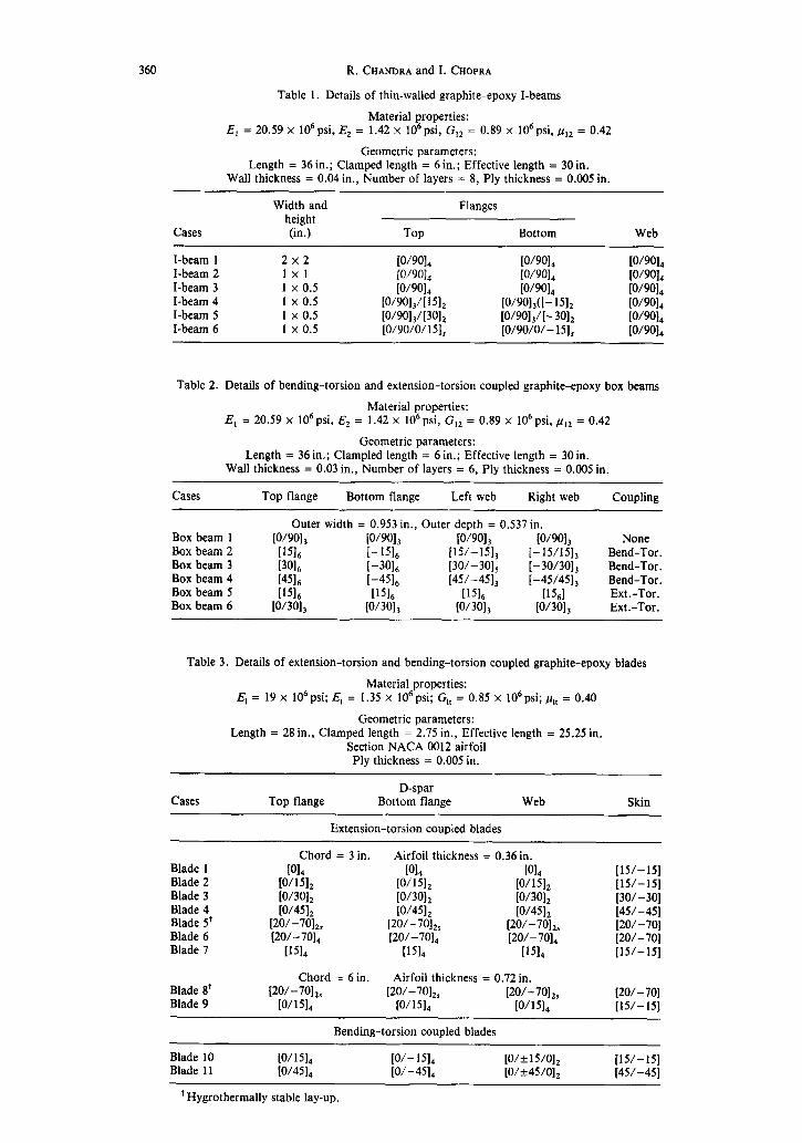
Table 1. Details of thin-walled graphite-epoxy I-beams
Material properties: E, = 20.59 x 10⁶psi, E, = 1.42 x 10⁶psi, G,, = 0.89 x 10⁶psi,~,, = 0.42
Geometric parameters: Length = 36 in.; Clamped length = 6 in.; Effective length = 30 in.
Wall thickness = 0.04 in., Number of layers = 8, Ply thickness = 0.005 in.
Cases
I-beam 1 I-beam 2 I-beam 3 I-beam 4 I-beam 5 I-beam 6
Width and height (in.)
2x2 1X1
1 x 0.5 1 x 0.5 1 x 0.5 1 x 0.5
Flanges
Top Bottom Web
ww‘l ww, ww, w01, 10~901, ww, Pow, ww, W9%
wol,m~l, ww,([- 151, w01, P~w,mol, [O/901,/[-301, ww, [O/90/0/ 151, [O/90/0/-15], ww,
Table 2. Details of bending-torsion and extension-torsion coupled graphite-epoxy box beams
Material properties: E, = 20.59 x 10⁶psi, E2 = 1.42 x 10⁶psi, G,, = 0.89 x 10⁶psi, F,~ = 0.42
Geometric parameters: Length = 36 in.; Clampled length = 6 in.; Effective length = 30 in.
Wall thickness = 0.03 in., Number of layers = 6, Ply thickness = 0.005 in.
Cases
Box beam 1 Box beam 2 Box beam 3 Box beam 4 Box beam 5 Box beam 6
Top flange Bottom flange Left web Right web
Outer width = 0.953 in., Outer depth = 0.537 in. w9013 10/9% w901, IO/W,
[1516 [-I516 [15/-151, I--151151, i30i6 k30i6 [30/-301, [-30/30], f4516 [-4516 [45/-451, [-45/45],
Ii516 Ii516 v5i6 b56i [O/301, [O/301, [O/301, [O/301,
Coupling
None Bend-Tor. Bend-Tor . Bend-Tor. Ext.-Tor. Ext.-Tor.
Table 3. Details of extension-torsion and bending-torsion coupled graphite-epoxy blades
Material properties: E, = 19 x 106psi; E, = 1.35 x 10⁶psi; G,, = 0.85 x 10⁶psi; ,u,, = 0.40
Geometric parameters: Length = 28 in., Clamped length = 2.75 in., Effective length = 25.25 in.
Section NACA 0012 airfoil Ply thickness = 0.005 in.
Cases Top flange D-spar
Bottom flange Web Skin
Extension-torsion coupled blades
Blade 1 Blade 2 Blade 3 Blade 4 Blade 5’ Blade 6 Blade 7
Blade 8’ Blade 9
Chord = 3 in. Airfoil thickness = 0.36 in. mi Ku, WI,
[O/151, [O/151, [O/151, [O/301, [O/301, [O/301, w/451, [O/451, [O/451,
[20/-70],, [20/-70],, [20/-70],, (20/-701, [20/k701, [20/-701,
D51, P5l.i v51,
Chord = 6in. Airfoil thickness = 0.72 in. [20/-70],, [20/-7012, [20/-70],,
w51, w51, [O/151,
Bending-torsion coupled blades
[15/-151 [15/-151 [30/-301 [45/-451 [20/-701 [20/-701 [15/-151
[20/-701 [15/-151
Blade 10 Blade 11
[O/151, [O/-15], [15/-151 [O/k 15/O], [O/451, [O/-45], [o/+45/0], [45/-451
’ Hygrothermally stable lay-up.

Two-cell rotor blades
Composite beams and blades 361
Two-cell composite rotor blades with a foam core were fabricated using a matched- die molding technique. There are three important aspects of this process. These are: the making of the rigid foam core, the making of the foam-filled spar, and finally the making of the spar-skin-foam rotor blade. The foam core in the required airfoil shape is built using the compression molding technique. In this method, a rough-machined ROHACELL blank foam is placed in a heated mold (350OF) and formed to the desired geometry by means of compression provided by fastening the mold. This foam core is cut into two pieces to provide cores for the D-spar and trailing edge separately. First, a composite D-spare is built using matched-die molding technique. For this, the desired number of composite prepreg layers are laid on to the foam core and each layer is compacted by means of a vacuum pump. The lay-up with foam is placed in the mold and the assembly is kept in an oven for curing. Thus, a D-spar is fabricated. Figure 4 shows a schematic of the mold used to fabricate the D-spar as well as the blade. In order to make a two-cell blade, the cured spar and trailing edge are wrapped by [+8/-191 layers as a skin, and vacuum compacted. This lay-up is kept in the mold and cured in an oven. Thus, several bending-torsion and extension-torsion coupled graphite-epoxy rotor blades of 28 in. length, 3 in. width and 0.36 in. depth were fabricated in this manner. Table 3 shows the details of these blades.
STATIC STRUCTURAL TESTING
The coupled beams and blades were tested under bending, torsional and extensional loads for their structural response. Tip loads were applied by means of dead weights and pulleys, using a simple test set-up (Chandra et al., 1990). The bending slope and twist of a generic point on the beam were measured using a 0.165 in. diameter mirror and a 2 mW helium-neon laser. To reduce measurement error, laser-dot deflections of the order of 10 in. over a distance of 282 in. were used. Different load levels were used on various beams to get laser dot-deflections of this order. Different clamping and loading fixtures were used to simulate the proper clamping conditions for different beam specimens. Figure 5 shows a shematic of the clamped ends of various beams.
In order to avoid buckling of the web of the I-beam while clamping, the web was bolted between two metal inserts. At the loading end, a special fixture was used to ensure
a
Solid Beam Box Beam
I-Beam Rotor Blade Legend: a - Steel Clamps b - Metal Insert c - Specimen
Fig. 5. Clamped ends of various composite beams.

362 R. CHANDRA and I. CHOPRA
that the bending load passes through the shear center. Warping displacements at the clamped and loading ends were constrained in this test. For box beams, the clamped end was reinforced by means of a metal insert to provide a clamped condition. While testing extension-torsion coupled beams in tension, the loading end was permitted to twist by means of a special end fixture with a thrust bearing. Warping deformations at the clamped end were constrained. In order to provide proper clamping for blades, a mahogany insert was introduced in the blade at the fabrication stage. Also, the clamped end of the blade was further reinforced by means of outside aluminum clamps, which were machined accurately using numerically-controlled machining. While mirrors and a laser were used to measure the bending slope and twist of the blades, strain gages were used to measure the response under extensional loads.
RESULTS AND DISCUSSION
The salient features of thin-walled composite beam analysis are: constrained warping, modeling of walls of beams as general laminates, transverse shear deformation and elastic couplings. Keeping these nonclassical effects in view, the following section is written.
Constrained warping effect
Constraining the warping deformation of the beam either at the support or load point changes its torsional behavior. This effect is more pronounced for open-section beams, such as I-beams.
Figure 6 shows the influence of constrained warping on the torsional stiffness of several cantilevered I-beams subjected to a tip torsional load. The torsional stiffness is expressed in terms of relative torsional stiffness, which is the ratio of the torsional stiff- ness under a mixed condition of free and constrained warping to the torsional stiffness corresponding to free warping (St Venant torsion). It is seen from this figure that the relative torsional stiffness decreases with an increase in the constrained warping parameter, ,u, and reaches an asymptotic value of 1, which refers to the free-warping condition. The parameter P, which is a function of the cross-sectional stiffnesses and length, determines the influence of the constrained warping on the torsional stiffness of the beam. The influence of the constrained warping on the relative torsional stiffness becomes very significant for low values of P. For values of P larger than 40, the effect of constrained warping on torsional stiffness is negligible and then the beam torsional behavior is controlled by the St Venant torsion. For a cross-ply I-beam with a slenderness ratio of 15 (I-beam 1, p = 0.38), the relative torsional stiffness is 83, whereas for a cross-ply I-beam with a slenderness of 30 (I-beam 2, p = 1.53), it is 6.37. Section details of these beams are provided in Table 1. The influence of the composite material on the relative torsional
--
loo Relative
7
torsional stiffness 10 y
I-Beam 2 I-Beam 3
Aluminum I-beam
1 f
St. Venant Torsion 0.1 , I I
0.1 1 10 100
Constrained Warping Parameter, p
Fig. 6. Influence of constrained warping on the torsional stiffness of cantilevered I-beams (Chandra and Chopra, 199la).

Composite beams and blades
7
6
5
4
3
2
1
0 I-Beam 2 I-Beam 3
Slenderness ratio = 30 Slenderness ratio = 60
363
Relative torsional stiffness
Fig. 7. Torsional stiffnesses of graphite-epoxy I-beams subjected to tip torsional load (Chandra and Chopra, 1991a).
stiffness is illustrated by comparing the results for a cross-ply I-beam with a slenderness ratio of 60 (I-beam 3, p = 2.89) with an aluminum I-beam of identical slenderness ratio (,u = 6.45). Note that the value of the relative torsional stiffness for the cross-ply, compo- site I-beam is 2.62, whereas for the aluminum I-beam, this value becomes 1.52. This shows that the effect of constrained warping on the torsional stiffness is smaller for isotropic materials than for composites. Figure 7 shows calculated and experimental values of relative torsional stiffnesses of cross-ply I-beams for two slenderness ratios. A good correlation between theory and experiment is seen only when constrained warping is included in the analysis.
For the solid beams, thin-walled box beams and multi-cell thin-walled rotor blades examined in this paper, the constrained warping parameter, p, is generally above 40. Hence, the constrained warping effect is not important for these beams.
Flanges and webs as general laminates
Composite beams with flanges and webs made out of general composite laminates may be required in many engineering applications. Neglecting their local bending stiff- nesses may lead to a large error in the prediction of the structural response. This effect is illustrated for I-beams and rotor blades.
The bending-torsion coupling stiffness KZ5 for composite I-beam depends upon the stiffness coefficients B,, and D,, of the flanges. BIG refers to extension-twist coupling and D,, refers to bending-twist coupling of the plate segment of the I-beam. It is possible to select the flanges such that B,, is zero, meaning that the flanges are symmetric with respect to their own mid-surfaces. The 15” bending-torsion coupled graphite-epoxy I-beams (I-beam 4) are made out of flanges which are not symmetric with respect to their own mid-planes. Hence, B,, for these beams is nonzero. In order to assess the importance of including B,, in the analysis, I-beam 6, whose flanges are symmetric with respect to their own mid-planes, is examined analytically. Note that the number of plies and their orientation in the flanges of I-beam 4 and I-beam 6 are identical, but the stacking sequence is different (Table 1). Figure 8 shows the bending slope and induced twist of these beams under unit tip bending load. Because of a nonzero B,, in I-beam 4, the response of this beam is vastly different to that of I-beam 6.
Figure 9 shows the influence of the extension-twist coupling stiffness, B16, of the branches of the blade spar on the blade’s structural response under tip bending and tor- sional loads. The general plate segment of the spar of Blade 5 is symmetric with respect to its own mid-plane, and hence B16 equals zero. On the other hand, the spar of Blade 6 is made of laminates which are not symmetric with respect to their mid-plane and hence results in a nonzero B,, . B16 influences the bending slope of the blade by increasing the bending-transverse shear coupling Kz6. About a 25% increase in the bending slope due to B16 is noticed for this blade. Note that the twist is virtually unaffected by B16. This is
CDE 2:5/7-E

364 R. CHANDRA and I. CHOPRA
0.025 0.025 +
0.020 Response Response
0.020 j
Rad. Rad. 0.015 0.015 {
0.010 I
I-Beam 4 I-Beam 6 B =0
16
Fig. 8. Influence of the extension-twist coupling stiffness “&” of the flanges of a bending- torsion coupled I-beam on its induced twist under unit tip bending load (Chandra and Chopra,
1991a).
0.025
0.020
Response rad. 0.010
0.005
0.000
I 1 h-Blade 5
I Spar lay-up: [20/-7OJ,
B =0
0 Bl1:de 6 Spar lay-up f20/-7014
B16*”
Bending slope Twist
Fig. 9. Influence of “&” of the blade spar branches on the structural response of extension- torsion coupled rotor blades under unit tip bending and torsional loads (Chandra and Chopra,
1991c).
because the torsional stiffness of the blade does not depend upon B,, . It is clear that this effect will not’be captured if the bending stiffness of the wall of the blade is not included in the analysis, as done by Rehfield et al. (1988).
Transverse shear effect
The influence of transverse shear deformation on the structural response occurs in two ways: the direct transverse shear effect and the effect via transverse-shear-related couplings. The direct transverse shear effect is controlled by the slenderness ratio of the beam and its cross-sectional details, whereas the transverse shear related coupling effect is controlled by the geometry and lay-up of the cross-section only. This effect is shown below for box beams and rotor blades.
Figure 10 shows the influence of the direct transverse shear deformation on the tip bending slope of cantilevered beams under unit tip bending load. The shear correction factor is the ratio of the tip bending slope due to transverse shear deformation to the tip bending slope due to bending. The slenderness ratio has a significant influence on the Shear Correction Factor (SCF). For beams with a slenderness ratio of 10, the SCF value is less than lo%, whereas for beams with a slenderness ratio of 5 this value can become as high as 40%. Note that the lay-up of the beams has a small effect on the SCF. As the

Composite beams and blades
0.3 Shear
Correction Factor Oq2
0.1
0.0
365
Tip Bending Slope rad. 0.005
0.000
[1516 W3013 Aluminum
Fig. 10. Influence of transverse shear deformation on the tip bending slope of box beams.
ratio of shear modulus to Young’s modulus is much less for graphite-epoxy than for aluminum, the values of the SCF for composite beams are much higher than those of identical aluminum beams.
Figure 11 shows the influence of the bending-transverse shear coupling on the predicted tip bending slope of extension-torsion coupled beams under unit tip bending loads. Measured values are also shown. Transverse shear has a significant influence on response. A good correlation between analysis and experiment is achieved when the effect of transverse shear is included in the analysis. For the [15], box beam (Box beam 5), the bending-shear coupling increases the bending flexibility by about 40%. However, this effect is less pronounced for the [O/30], box beam (Box beam 6).
Figure 12 shows the influence of the bending-shear coupling on the bending slope of extension-torsion coupled blades subjected to unit tip bending load. Again, bending- shear coupling appears important. For the blade with a hygrothermally stable lay-up (Blade 5), bending-shear coupling increases the bending slope by about 50%.
0 Analysis w/o bending-shear coupling f3 Analysis with bending-shear coupling m Experiment
[1516 w3q
Fig. 11. Tip bending slope of extension-torsion coupled graphite-epoxy box beams under unit tip bending load.
Influence of ply orientation on elastic couplings
The influence of ply orientation on the structural response is presented for I-beams, box beams, rotor blades and solid beams.
Figure 13 shows the bending slope and induced twist of bending-torsion coupled I-beams subjected to a unit tip bending load. For uncoupled composite and metal beams, there will be no twist under bending loads. As shown, the induced twist due to bending

366 R. CHANDRA and I.CHOPRA
0.045 n Theory w/o bending-shear coupling 0 Theory with bending-shear coupliq :
1 1
Bending Slope rad. I
Blade 5 Blade 6
Fig. 12. Influence of bending-shear coupling on the bending slope of extension-torsion coupled blades (Chandra and Chopra, 1991~).
Induced
0.03 - Response .
rad. 0.02 -
: Bending . Slope 0.01 i
Induced Twist
1 L
I-Beam 4 I-Beam 5 15’ 30’
Fig. 13. Bending slope and induced twist at tip for bending-torsion coupled graphite-epoxy I-beams subjected to unit tip bending load.
Bending Slope rad.
0.05,
1.04 -
1.03 - Box beam
1.02
c ox beam 1
2
to1901 15’ 30’ 45’ Fig. 14. Tip bending slope due to unit tip bending loads for graphite-epoxy box beams.

Composite beams and blades 367
Induced 0.010 Tip Twist
rad.
0.005
0.000 45’
Box beam 2 Box beam 3 Box beam 4 Fig. 15. Induced tip twist due to unit tip bending loads for graphite-epoxy box beams.
very much depends on the lay-up of the composite beams. Note that the induced twist is about five times the bending slope for these beams under bending load.
Figures 14 and 15 present the influence of ply orientation on the tip bending slope and induced twist of graphite-epoxy box beams under unit tip bending loads. Box beam 1 consists of cross-ply laminates and has no bending-torsion coupling, whereas Box beams 2-4 consist of angle-ply laminates and have bending-torsion coupling. There is a good correlation between theory and experiment. Note that the bending slope and induced twist increase with an increase in ply orientation.
Figure 16 shows the tip twist of [15], and [O/30], graphite-epoxy box beams under unit tip torsional load. These beams have antisymmetry with respect to their mid-axes and result in extension-torsion and bending-shear couplings. The results of the present analysis correlate well with experimental data. Figure 17 shows the induced tip twist of these beams under unit axial load. Again, the extension-torsion coupling depends upon the composite lay-up.
Figure 18 shows the tip bending slope of several extension-torsion coupled blades under a unit tip bending load. Results corresponding to the one-cell theory are obtained by neglecting the web and treating the blade section as a single cell. As expected, the one- cell approximation overestimates the bending slope as compared to the two-cell theory, and the experimental results are generally closer to the two-cell analysis. The correlation between the two-cell analysis and experiment is within 7%. This figure also indicates the
0.004
Twist 0.002 rad.
Box Beam 5 Box Beam 6 D516 W3013
Fig. 16. Twist of extension-torsion coupled graphite-epoxy box beams under unit tip torsional load.

368 R. CHANDRA and I. CHOPRA
Induced Twist rad.
0.0002
0.0001
0.0000 - Box Beam 5
1154 Box Beam 6
[0/3013
Fig. 17. Induced twist of extension-torsion coupled graphite-epoxy box beams under unit tip axial load.
0.030
0.020
Bending Slope rad.
0.010
0.000
Fig. 18. Influence of lay-up on bending slope of extension-torsion coupled blades of slenderness ratio 72 under unit tip bending load (Chandra and Chopra, 1991~).
0.0030
Tip Twist rad.
0.0015
0.0000
Blade 1 Blade 2 Blade 3 Blade 4 Blade 5
11 1 Experiment
Blade 1 Blade 2 Blade 3 Blade 4 Blade 5
Fig. 19. Influence of lay-up on twist of extension-torsion coupled blades of slenderness ratio 72 under unit tip torsional load (Chandra and Chopra, 1991c).

Composite beams and blades 369
0.0005
0.0003
Tip Twist -rad. 0.0002
0.0001
0.0000 1
Blade 8 Blade 9 Fig. 20. Difference between single-cell and two-cell predictions of twist of extension-torsion coupled blades of slenderness ratio 36 under unit tip torsional load (Chandra and Chopra, 1991~).
n Theory (one-cell) 0 Theory (two-cell)
influence of lay-up of blades on bending flexibility; the bending flexibility becomes maximum for a 45” fiber orientation (Blade 4). Figure 19 illustrates the tip twist of these blades under unit tip torsional load. Again, the one-cell approximation overestimates the elastic twist and the correlation between the two-cell analysis and the experiment is within 7%. As expected, minimum torsional flexibility occurs for the blade with 45” fiber orienta- tion (Blade 4). The difference between the one-cell and two-cell predictions depends upon the blade lay-up and type of loading. For example, under bending load, the maximum difference takes place for the 45” blade (Blade 4), whereas under torsional load, the maxi- mum difference corresponds to the blade with the hygrothermally stable lay-up (Blade 5).
It is seen from Figs 18 and 19 that the difference between the one-cell and two-cell predictions is within 20% for these blades. In order to further explore the importance of multi-cell analysis, shorter blades of slenderness ratio 36 were examined. Figure 20 shows the torsional flexibility (tip twist per unit torsional load) predictions obtained using one-cell and two-cell analyses. For these configurations, the difference between the one-cell and two-cell predictions is quite significant. For the blade with the hygrothermally stable lay-up (Blade 8), the torsional flexibility as predicted by the one-cell analysis is about twice the value predicted by the two-cell analysis.
Figure 21 shows the induced twist rates for two blade configurations (Blades 5 and 7) under axial force. Good correlation between theory and experiment is achieved. The hygrothermally stable lay-up (Blade 5) provides an induced twist rate of 0.025 deg. in;’ at an axial force of 100 lbs. In order to assess the load-carrying capability of this blade under
0.030
0.025 -
0.020 -
Twist rate 0.015 _ deg./in.
0.010 -
0.005 -
0.000 Blade 5 Blade 7
Fig. 21. Twist rates of extension-torsion coupled rotor blades under axial force (Chandra and Chopra, 1991~).

370 R. CHANDRA and I. CHOPRA
0.010
0.008
: 0.006
Response rad.
0.004 I
0.002
0.000 i
Theory
n Experiment I
Tip Bending slope Tip Induced twist
Fig. 22. Response of bending-torsion coupled rotor blade (Blade 10) under unit tip bending load (Chandra and Chopra (1991d).
0.003 /
0 Theory
n Experiment I
0.002
Response rad.
0.001
Tip Twist Tip Induced Bending
Fig. 23. Response of bending-torsion coupled rotor blade (Blade 10) under unit tip torsional load (Chandra and Chopra, 1991d).
Fensile 40.0 strain
microstrain 30.0
20.0
10.0
0.0 Blade 10 Blade 11
Fig. 24. Structural response of bending-torsion coupled blades under extensional loads (Chandra and Chopra, 1991d)

Composite beams and blades 371
Bending slope Induced twist
Fig. 25. Structural response of a 15” solid beam at the tip due to a unit tip bending load.
extensional load, the strain levels in its different branches were computed. The maximum strains were of the order of 800 microstrains at an axial load of 1000 lbs.; these values are well within the material allowables of the blade. This implies that the blade may be able to resist a 1000 lb. axial load. Note that the induced twist rate of this blade at 1000 lbs. would be of the order of 0.25 deg. in:‘. This value may be sufficient in satisfying the requirement for the design of extension-twist coupled tilt rotor blades JVX and XV-15 rotors (Nixon, 1987).
Figure 22 shows the tip bending slope and induced twist of the bending-torsion coupled blade, Blade 10, under unit tip bending load. Good correlation between theory and experiment for bending slope and induced twist is achieved. Figure 23 illustrates the tip twist and induced slope for this blade under unit tip torsional load. Again, good correlation between theory and experiment is noted. Note that the amount of bending-torsion coupling in this blade is rather low as compared to the box beams due to the difference in lay-up and geometry of the section.
Figure 24 shows the uniform tensile strain in bending-torsion coupled blades (Blades 10 and 11) under tensile load. Good correlation between analysis and experiment is seen in this figure. The analytical results include extension-transverse shear couplings. The influence of extension-transverse shear coupling in the bending-torsion coupled blade is to reduce its extensional stiffness. This reduction for the blades examined in the present study is small (about 5% for Blade 10).
The structural response of the [15],, bending-torsion coupled graphite-epoxy solid beam is presented in Figs 25 and 26. The dimensions of this beam are: width = 1.75 in.,
Structural 0.02 response
rad.
0.01
Twist Induced bending slope Fig. 26. Structural response of a 15” solid beam at the tip due to a unit tip torsional load.

372 R. CHANDRA and I. CHOPRA
thickness = 0.11 in. and effective length = 30.25 in. The bending load and torque are applied separately at the tip and tip bending slope and twist are determined. Good correla- tion between theory and experiment is achieved. For this beam, the induced twist and bending slope due to unit tip bending load are of the same order.
CONCLUSION
The Vlasov theory is expanded to perform a linear analysis of open- and closed- section beams made out of general composite laminates. Transverse shear deformation of the beams is accounted for in the theory. In order to provide experimental correlation to the theory, graphite-epoxy beams of various cross-sections like solid rectangular, I-beam and box beam, and two-cell airfoil covering parameters, such as ply orientation and slenderness ratio, were fabricated and tested for their structural response under tip bending, torsional and extensional loads. The structural response in terms of bending slope and twist was measured using a mirror and laser system. Good correlation between theory and experiment was achieved. Based on this study, the following conclusions are drawn:
(1)
(2)
(3)
(4)
(5)
(6)
The torsional stiffness of I-beams is significantly influenced by restraining the warping deformations of the beam. About 260-630% increase in torsional stiff- ness because of constrained warping was seen for the graphite-epoxy I-beams. The bending-torsion coupled behavior of I-beams is influenced by the bending- twist and extension-twist couplings of its plate segments. Extension-twist coupling of plate segments increases the bending-induced twist of the examined beams by 500%. The influence of bending-transverse shear and extension-torsion coupling on the structural behavior of coupled blades depends upon the ply lay-up in the section. For a blade with a hygrothermally stable lay-up, the bending-transverse shear coupling increased the bending flexibility by about 50%. The difference between two-cell and one-cell predictions depends upon the slenderness ratio and the blade lay-up. For example, for a blade with a hygrothermally stable lay-up and slenderness ratio of 36, the one-cell analysis overestimated the torsional flexibility by about 100%. The branches of a generally coupled composite rotor blade must be modeled as general composite laminates. For example, a nonzero B,, of a general plate segment of a blade spar with a hygrothermally stable lay-up increased its bending slope by about 25% by increasing the bending-transverse shear coupling. An induced twist rate of the order of 0.25“ per inch length in a blade with a hygrothermally stable configuration can be achieved by an axial load of 1000 lbs. Such coupled blades can be exploited for tilt-rotor design.
Acknowledgements-This research work was supported by the Army Research Office under contract number DAAL-03-88-C-022. The Technical Monitors are Dr Robert Singleton and Dr Tom Doligalski.
REFERENCES
Bauchau, 0. A. (1987). Large displacement analysis of naturally curved and twisted composite beams. AIAA JI 25, 1469-1415.
Borri, M. (1986). A large displacement formulation for anisotropic beam analysis. Meccanica 21, 30-37. Chandra, R. and Chopra, I. (1991a). Experimental and theoretical analysis of composite I-beams with elastic
couplings. AZAA Jt 29, 2197-2206. Chandra, R. and Chopra, I. (1991b). Vibration characteristics of composite I-beams with elastic couplings under
rotation. Proc. 47th Annual Forum of American Helicopter Society, Phoenix, Arizona. Chandra, R. and Chopra, I. (1991~). Structural behavior of two-cell composite rotor blades with elastic
couplings. Proc. 17th European Rotorcraft Forum, Berlin, Germany. Chandra, R. and Chopra, I. (1991d). Coupled composite rotor blades under bending and torsional loads. Proc.
AHS Specialists’ Meeting on Rotorcraft Structures, Williamsburg, VA. Chandra, R. and Chopra, I. (1992). Experimental-theoretical investigation of the vibration characteristics of
rotating composite box beams. Accepted for publication in the J. Aircraft. Chandra, R., Stemple, A. D. and Chopra, I. (1990). Thin-walled composite beams under bending, torsional and
extensional loads. J. Aircraft 21, 619-627. Ciiavotto, V. et al. (1983). Anisotropic beam theory and application. Comput. Struct. 16, 403-413.
Composite beams and blades 313
Gjelsvik, A. (1981). The Theory of Thin-walled Bars. John Wiley, New York. Hodges, D. H., Atilgan, A. R., Fulton, M. V. and Rehfield, L. W. (1991). Free-vibration analysis of composite
beams. J. Am. Helicopter Sot. 36, 36-41. Hodges, D. H. and Dowell, E. H. (1974). Nonlinear equations of motion for the elastic bending and torsion of
twisted nonuniform rotor blades. NASA TN D-7818. Hong, C. H. and Chopra, I. (1985). Aeroelastic stability of a composite blade. J. Am. Helicopter Sot. 30,
51-61. Kosmatka, J. B. (1991). Extension-bend-twist coupling behavior of thin-walled advanced composite beams with
initial twist. Proc. 32nd AZAA/ASME/ASCE/AHS/ASC Structures, Structural Dyanamics and Materials Conf. AIAA, Washington, DC.
Megson, T. H. G. (1974). Linear Analysis of Thin-walled Elastic Structures. John Wiley, New York. Minguet, P. and Dugundji, J. (1990a). Experiments and analysis for composite blades under large deflections,
Part 1: Static behavior. AZAA JI 28, 1573-1579. Minguet, P. and Dugundji, J. (1990b). Experiments and analysis for composite blades under large deflections,
Part 2: Dynamic behavior. AZAA JI 28, 1580-1588. Nixon, M. W. (1987). Extension-twist coupling of composite circular tubes with application to tilt rotor blade
design. Proc. 28th AZAA/ASME/ASCE/AHS/ASC Structures, Structural Dynamics and Materials Conf. AIAA, Washington, DC.
Rehfield, L. W. and Atilgan, A. R. (1989). On the buckling behavior of thin walled laminated composite open section beams. Proc. 30th AZAA/ASME/ASCE/AHS/ASC Structures, Structural Dynamics and Materials Conf. AIAA, Washington, DC.
Rehfield, L. W., Atilgan, A. R. and Hodges, D. H. (1988). Structural modeling for multicell composite rotor blades. Proc. 28th AZAA/ASME/ASCE/AHS/ASC Structures, Structural Dynamics and Materials Conf. AIAA, Washington, DC.
Rehfield, L. W., Atilgan, A. R. and Hodges, D. H. (1990). Nonclassical behavior of thin-walled composite beams with closed cross-sections. J. Am. Helicopter Sot. 35, 42-51.
Smith, E. C. and Chopra, I. (1991). Formulation and evaluation of an analytical model for composite box beams. J. Am. Helicopter Sot. 36, 23-35.
Vlasov, V. Z. (1961). Thin-walled Elastic Beams (translated from Russian). National Science Foundation and Department of Commerce, U.S.A.
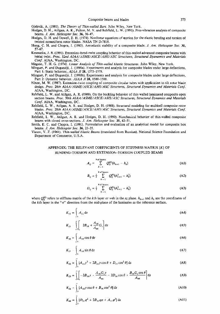
APPENDIX: THE RELEVANT COEFFICIENTS OF STIFFNESS MATRIX [K] OF BENDING-TORSION AND EXTENSION-TORSION COUPLED BEAMS
#of layers A, = C Qr’(h,+, - h,J
k=l (AlI
Bji = + c. Q$‘(h;+, - hi)
D, = + c Q;‘(h;+, - h:) k=,
(‘43)
where Q$’ refers to stiffness matrix of the kth layer or web in the sz plane. hr+, and h, are the coordinates of the kth layer in the “n” direction from the mid-plane of the laminates as the reference surface.
(‘44)
K,, = S[ -2B,, + $%$ ds s 66 1
(A51
K,, = A,,cosBds 1
(‘46) 5
K,, = s
[A,,y’+ 2B,,ycosB+ D,,cos21?]ds (‘48) I
Kz, = S[ A,,Gsy -2B,,y + - - 24, COS e + B,,G, COS e ds
s A66 A
66 1 Kz6 = [A,ey cos 6 + B,, cos’ 01 ds (Al’3
5
L = s
[D,,q2 + 2B,,w + A,,v’l ds (Al 1) 5

374 R. CHANDRA and I. CHOPRA
6, = G,2 &Gs ds 4D,,+A-4-
66 ‘466 I
Ke6 = s
A,, cos2 0 ds s
KT7 = 3
A,, sin2 8 ds. 5
C4W
(A131
(A141