Matsudo · Author: m5730136 Created Date: 6/28/2017 1:50:58 PM
STRUCTURAL COMPLEXITIES
IN
SYNTHETIC SELF-ASSEMBLING NANOMATERIALS
A Dissertation
Presented to the Faculty of the Graduate School
of Cornell University
In Partial Fulfillment of the Requirements for the Degree of
Doctor of Philosophy
by
Hiroaki Sai
January, 2013

© 2013 Hiroaki Sai
STRUCTURAL COMPLEXITIES IN SYNTHETIC NANOMATERIALS
Hiroaki Sai, Ph. D.
Cornell University, 2013
Self-assembly of amphiphilic molecules such as surfactants and amphiphilic block
copolymers (BCPs), provides an energy-efficient bottom-up approach for controllably
creating structures at the mesoscale (2-50 nm) with potential applications in catalysis,
next-generation energy production and storage devices, optical metamaterials and
bioengineered materials. Biological systems serve as examples of complex materials at
mesoscopic length scales that integrate structural and compositional heterogeneities
that lead to functions including toughness, optical iridescence and van der Waals
adhesion due to large surface area.
In this dissertation, I will describe three different approaches for adding structural
complexity to synthetic mesoscale structures. Firstly, controlled synthesis and detailed
characterization of multicompartment mesoporous silica nanoparticles (multi-MSNs)
from surfactant coassembly with sol-gel silica is described. These multi-MSNs consist
of a core with cage-like cubic mesoporous network morphology and up to four
fingers/branches with hexagonally packed cylindrical mesopores epitaxially emanating
from the vertices of the cubic core. These multi-MSNs are mesoscale structural
analogues to branched semiconductor nanocrystals. Possible nucleation and growth
processes leading to this particle morphology are discussed. Secondly,
multicomponent evaporation-induced self-assembly behavior of ligand-stabilized
platinum nanoparticles (Pt NPs) with poly(isoprene-block-dimethylaminoethyl
methacrylate) block copolymers is discussed. Detailed characterization on Pt NPs
revealed sparse ligand coverage. Changing the volume fraction of Pt NPs in BCP-NP
composites yielded organic-inorganic hybrids with spherical micellar, wormlike
micellar, lamellar and inverse hexagonal mesoscale morphologies. Disassembly of
hybrids with spherical, wormlike micellar, and lamellar morphologies generated
isolated metal-NP based nanospheres, cylinders and sheets, respectively. Results
suggest the existence of powerful design criteria for the formation of metal-based
nanostructures from designer blocked macromolecules. Finally, a facile synthesis
protocol for hierarchically structured polymeric scaffolds with highly ordered
mesopores is introduced. Mixtures of poly(styrene-block-ethylene oxide) BCPs with
oligomeric poly(ethylene oxide) additives were dissolved in high boiling point
solvents, and bulk films were cast through solvent evaporation. Spinodal
decomposition of the BCP/additive mixture resulted in macrostructure formation, with
the BCP-rich domains forming ordered mesostructures. Facile washing of the films
resulted in the formation of macro/meso-porous three-dimensional polymer scaffolds.
Experimental parameters relevant for structure formation including additive molecular
weights, solvents and drying temperatures are explored.
iii
BIOGRAPHICAL SKETCH
Hiroaki Sai was born in Matsudo, Chiba Pref. Japan on October 20th, 1984.
After moving to Yokohama, he went to Kenzan Elementary School. In the September
of 1992, he was absolutely thrilled to watch the Space Shuttle Endeavor launch with
the first Japanese astronaut on the television, which eventually became his first source
of motivation for studying in the field of science and technology. From 1997 to 2003,
Hiro attended Eiko Gakuen High School, where he was inspired by splendid friends
and the beautiful surroundings of Kamakura. The teachers in Eiko High gave him
tremendous amount of care and mentoring through various opportunities, such as
reading Euclid’s Elements, club activity camp for stargazing with a telescope, playing
violin in the school orchestra, and providing laboratory experiences in chemistry,
which prepared him for the winning the Chemical Society of Japan Award in the
Japanese National High School Chemistry Olympiad in 2002.
After a short period of enrollment in the University of Tokyo, Hiro travelled
overseas for the second time in his life (his first time was a five-day trip to Hong Kong
for a math competition when he was 11 years old) to commence his study at Princeton
University as a member of the Class of 2007. Under the supervision of Prof. Ilhan
Aksay in the Department of Chemical Engineering, Hiro started to work in the
Ceramic Materials Laboratory on the mesoporous silica formation under capillary
electroosmotic flow. His interest for materials science and engineering grew with this
laboratory experience, and he subsequently stayed in the lab for the next three years
till the senior thesis project, in which the mechanical properties of L3 sponge-phase
templated silica were investigated. Outside of laboratory and classrooms, Hiro served
as an undergraduate Residential College Advisor in the Butler College in Princeton for
two years, first as an assistant advisor and then full, where he made friends with Hiro
iv
graduated from Princeton University in the May of 2007 as a Bachelor of Science in
Engineering with Highest Honors. From the fall of 2007, Hiro has attended graduate
school in the Department of Materials Science and Engineering in Cornell University
in the research group of Prof. Ulrich Wiesner, with Profs. Lara A. Estroff and Sol M.
Gruner as co-advisors.

v
This dissertation is dedicated to each and every one who interacted with me in the past.
Without you, I would not have been able to stand where I am now.
vi
ACKNOWLEDGMENTS
I would like to first thank my advisors, Profs. Uli Wiesner, Lara A. Estroff and
Sol M. Gruner. Without doubt they have been the best possible mentors for me for the
past five years, and the people I look up to as role models. They have been always
understanding, cheerful, open to discussion, and full of inspirations and helpful
suggestions. After five years I believe they have some magical powers to keep me
excited about new opportunities, which I hope I inherited from them.
My five years in the Wiesner group should best be characterized by encounters
with the best team of colleagues I could ever hope for. I would like to thank Prof.
Marleen Kamperman who taught me how to use the Schlenk line to synthesize
polymers on the week I joined the group, Dr. Scott Warren who inspired me how
much fun you can have with the various equipment in the labs, Dr Hitesh Arora with
whom we had countless discussions and sometimes inpromptu happy hours, Dr Chris
Orilall and Dr. Morgan Stefik who were not only splendid collaborators with
enthusiasm for energy conversion/storage materials but also great fun to keep
company with in the office, and Prof. Jinwoo Lee who has been very nice to me and I
remember sharing the office many nights before he went back to Korea. On the C-dot
side I would especially like to thank Dr. Teeraporn (Aey) Suteewong who pulled me
back from block copolymer world into mesoporous silica nanoparticles, and for
helpful advice on the academic world. Zihui (Cathy) Li is a special colleague of mine
in that we shared a lot of moments together and shared the first paper. Dr. Juho Song
always amazed me with his neatness both in lab and in real life. Dr. Kahyun Hur, who
gave deep insights into experimental results from his simulation viewpoint, has taken
me out of lab many times so that I do not miss out the Upstate New York experience,
for which I am very grateful. Dr. Tobias Hoheisel helped me greatly in the last year
with his expertise in organic chemistry. Rachel Dorin, Joerg Werner, Paul Kim,
vii
Spencer Robbins, Kwan Wee Tan, Christina Cowman, Yibei Gu, and recently Ji-yeob
Kim were all great office-mates in Thurston 304 and I greatly enjoyed the countless
discussions we had, be it research-related or completely tangential. I would like to
thank all of the Wiesner group members, past and present, for bearing with my
sometimes-endless questions in the group meetings and fun times in group activities.
Finally, I would like to thank Dolores Dewbury, as known as the magic person we
could rely on for any administrative issues.
By participating in other groups than my main research group, I was fortunate
to be able to take a glimpse of completely different projects and learning perspectives
I would never have thought of. I would like to thank the Estroff group members,
especially Dr. Jason Dorvee and Dr. Debra Lin and Dr. Ruiqi Song for the
hydroxyapatite project. I would like to thank the Gruner group members, especially Dr.
Mark Tate who taught me on the rotating anode beamline, Dr. Suntao Wang who
collaborated with the terpolymer hybrid analysis, and Dr. Yi-fan Chen for instruction
on the high-pressure beryllium cell setup.
It was a great privilege working with many people other than graduate students
in our groups: these include the suite of enthusiastic undergrads Patrick Kiernan,
Christopher Sarra, Samantha Smith, Andrea Bowring, Alden Coots and Dan Shae,
visiting professors and scientists Yuzo Fujiki, Prof. Taeghwan Hyeon, Tatsuro
Morimoto, Stefan Guldin, Kazufumi Kawahara, Rina Maeda, Prof. Byoung-Ki Cho
and Prof. Rodrigo Orefice, and other external collaborators Joshua Choi, Will
Baumgardner, Dave Moore, Robert Hovden, Mihaela Nedelcu, Azusa Takai, and
Asuka Toda.
Virtually none of the characterization work could have been done without the
facility managers. I would like to thank the Cornell Center of Materials Research
(CCMR) staff: Dr. John Hunt, Dr. John Grazul, Dr. Mick Thomas and Dr. Yuanming
viii
Zhang for the microscopy facility, Dr. Anthony Condo for the polymer facility, Dr.
Maura Weathers for the x-ray facility and Paul Bishop and Phil Carubia for the
materials research facility. I would also like to thank Dr. Ivan Keresztes for the NMR
facility and Dr. Mark Riccio for the NanoCT facility. People at Cornell High Energy
Synchrotron Source (CHESS) have greatly helped me: I would like to thank Dr.
Arthur Woll in G-line, Dr. Detlef Smilgies in D1 for experimental assistance.
Life in Ithaca with cold weather and little attraction would not have been this
easy and much fun without any of our friends. I would like to especially thank Lou
and Erin Estevez, Dr. Miki Kunitake, Erin Riley, Dr. Alwin Wan, Dr. Mike
Willemann, Michelle Wu for bringing me out of lab to fun events. I must also mention
that the Starbucks coffee shop in Collegetown was my means of survival, and would
like to thank all the baristas for conveniences and caffeine they have given me.
Finally, I would like to thank my girlfriend Arisa, and my family: mom, dad
and my sister for continuous love and support.
ix
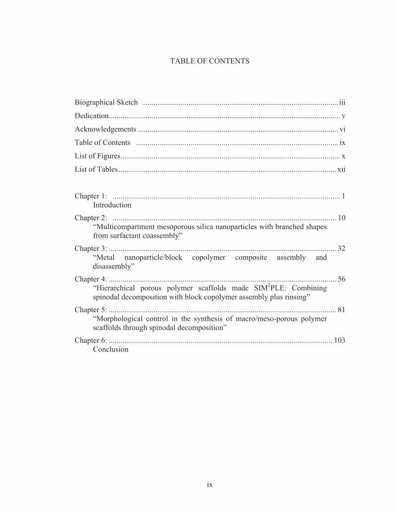
TABLE OF CONTENTS
Biographical Sketch ..................................................................................................... iii
Dedication ....................................................................................................................... v
Acknowledgements ....................................................................................................... vi
Table of Contents ........................................................................................................ ix
List of Figures ................................................................................................................. x
List of Tables ................................................................................................................ xii
Chapter 1: ..................................................................................................................... 1 Introduction
Chapter 2: ................................................................................................................... 10 “Multicompartment mesoporous silica nanoparticles with branched shapes from surfactant coassembly”
Chapter 3: ..................................................................................................................... 32 “Metal nanoparticle/block copolymer composite assembly and disassembly”
Chapter 4: ..................................................................................................................... 56 “Hierarchical porous polymer scaffolds made SIM2PLE: Combining spinodal decomposition with block copolymer assembly plus rinsing”
Chapter 5: ..................................................................................................................... 81 “Morphological control in the synthesis of macro/meso-porous polymer scaffolds through spinodal decomposition”
Chapter 6: ................................................................................................................... 103 Conclusion
x
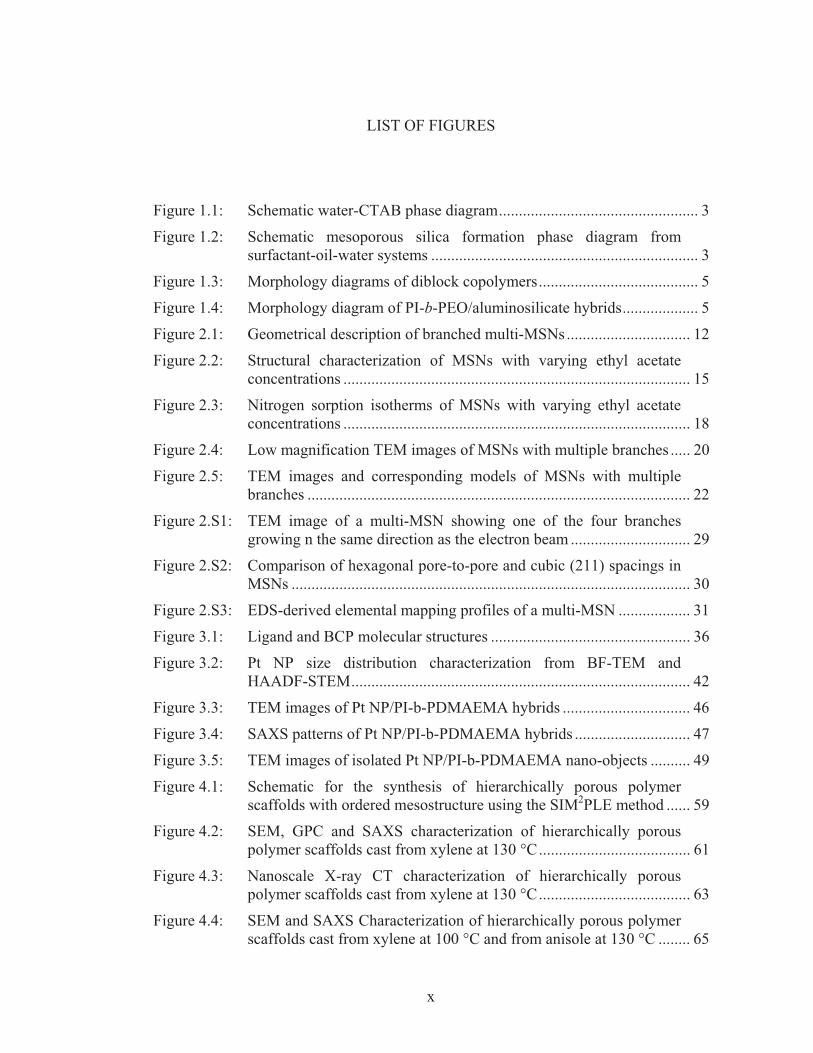
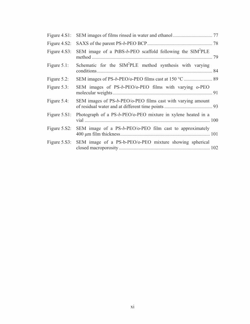
LIST OF FIGURES
Figure 1.1: Schematic water-CTAB phase diagram .................................................. 3
Figure 1.2: Schematic mesoporous silica formation phase diagram from surfactant-oil-water systems ................................................................... 3
Figure 1.3: Morphology diagrams of diblock copolymers ........................................ 5
Figure 1.4: Morphology diagram of PI-b-PEO/aluminosilicate hybrids ................... 5
Figure 2.1: Geometrical description of branched multi-MSNs ............................... 12
Figure 2.2: Structural characterization of MSNs with varying ethyl acetate concentrations ....................................................................................... 15
Figure 2.3: Nitrogen sorption isotherms of MSNs with varying ethyl acetate concentrations ....................................................................................... 18
Figure 2.4: Low magnification TEM images of MSNs with multiple branches ..... 20
Figure 2.5: TEM images and corresponding models of MSNs with multiple branches ................................................................................................ 22
Figure 2.S1: TEM image of a multi-MSN showing one of the four branches growing n the same direction as the electron beam .............................. 29
Figure 2.S2: Comparison of hexagonal pore-to-pore and cubic (211) spacings in MSNs .................................................................................................... 30
Figure 2.S3: EDS-derived elemental mapping profiles of a multi-MSN .................. 31
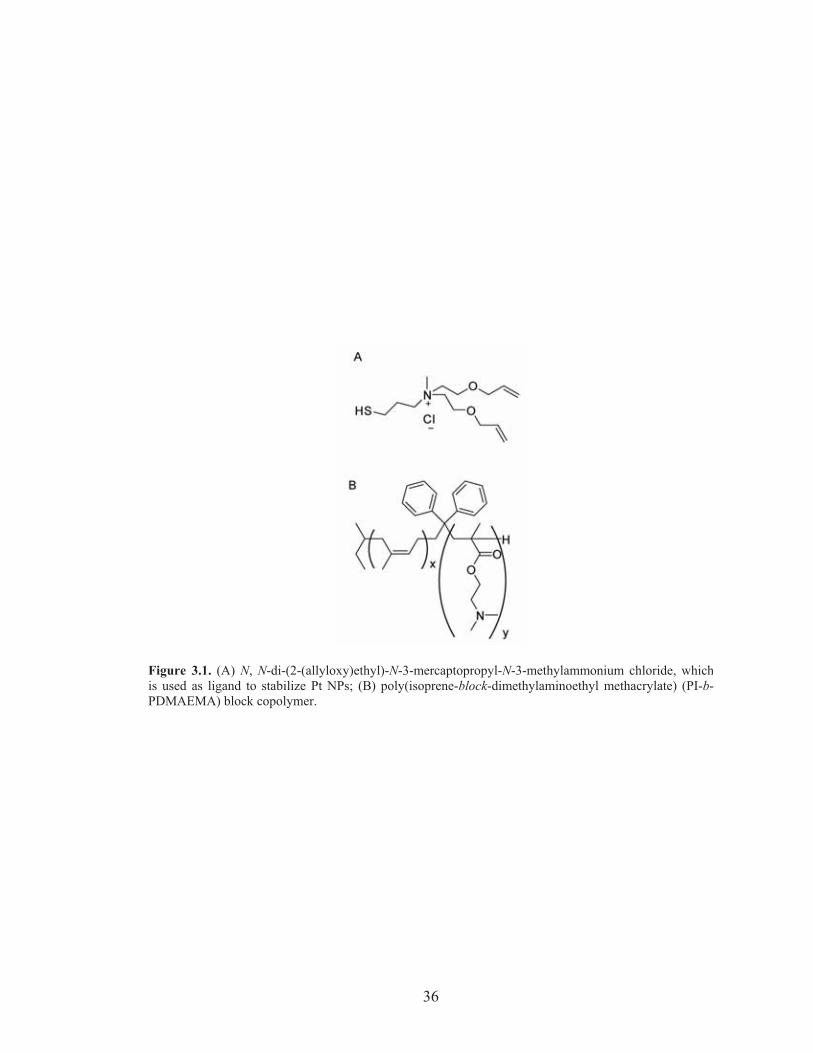
Figure 3.1: Ligand and BCP molecular structures .................................................. 36
Figure 3.2: Pt NP size distribution characterization from BF-TEM and HAADF-STEM ..................................................................................... 42
Figure 3.3: TEM images of Pt NP/PI-b-PDMAEMA hybrids ................................ 46
Figure 3.4: SAXS patterns of Pt NP/PI-b-PDMAEMA hybrids ............................. 47
Figure 3.5: TEM images of isolated Pt NP/PI-b-PDMAEMA nano-objects .......... 49
Figure 4.1: Schematic for the synthesis of hierarchically porous polymer scaffolds with ordered mesostructure using the SIM2PLE method ...... 59
Figure 4.2: SEM, GPC and SAXS characterization of hierarchically porous polymer scaffolds cast from xylene at 130 °C ...................................... 61
Figure 4.3: Nanoscale X-ray CT characterization of hierarchically porous polymer scaffolds cast from xylene at 130 °C ...................................... 63
Figure 4.4: SEM and SAXS Characterization of hierarchically porous polymer scaffolds cast from xylene at 100 °C and from anisole at 130 °C ........ 65
xi
Figure 4.S1: SEM images of films rinsed in water and ethanol ................................ 77
Figure 4.S2: SAXS of the parent PS-b-PEO BCP ..................................................... 78
Figure 4.S3: SEM image of a PtBS-b-PEO scaffold following the SIM2PLE method .................................................................................................. 79
Figure 5.1: Schematic for the SIM2PLE method synthesis with varying conditions .............................................................................................. 84
Figure 5.2: SEM images of PS-b-PEO/o-PEO films cast at 150 °C ....................... 89
Figure 5.3: SEM images of PS-b-PEO/o-PEO films with varying o-PEO molecular weights ................................................................................. 91
Figure 5.4: SEM images of PS-b-PEO/o-PEO films cast with varying amount of residual water and at different time points ....................................... 93
Figure 5.S1: Photograph of a PS-b-PEO/o-PEO mixture in xylene heated in a vial ...................................................................................................... 100
Figure 5.S2: SEM image of a PS-b-PEO/o-PEO film cast to approximately 400 �m film thickness ......................................................................... 101
Figure 5.S3: SEM image of a PS-b-PEO/o-PEO mixture showing spherical closed macroporosity .......................................................................... 102
xii
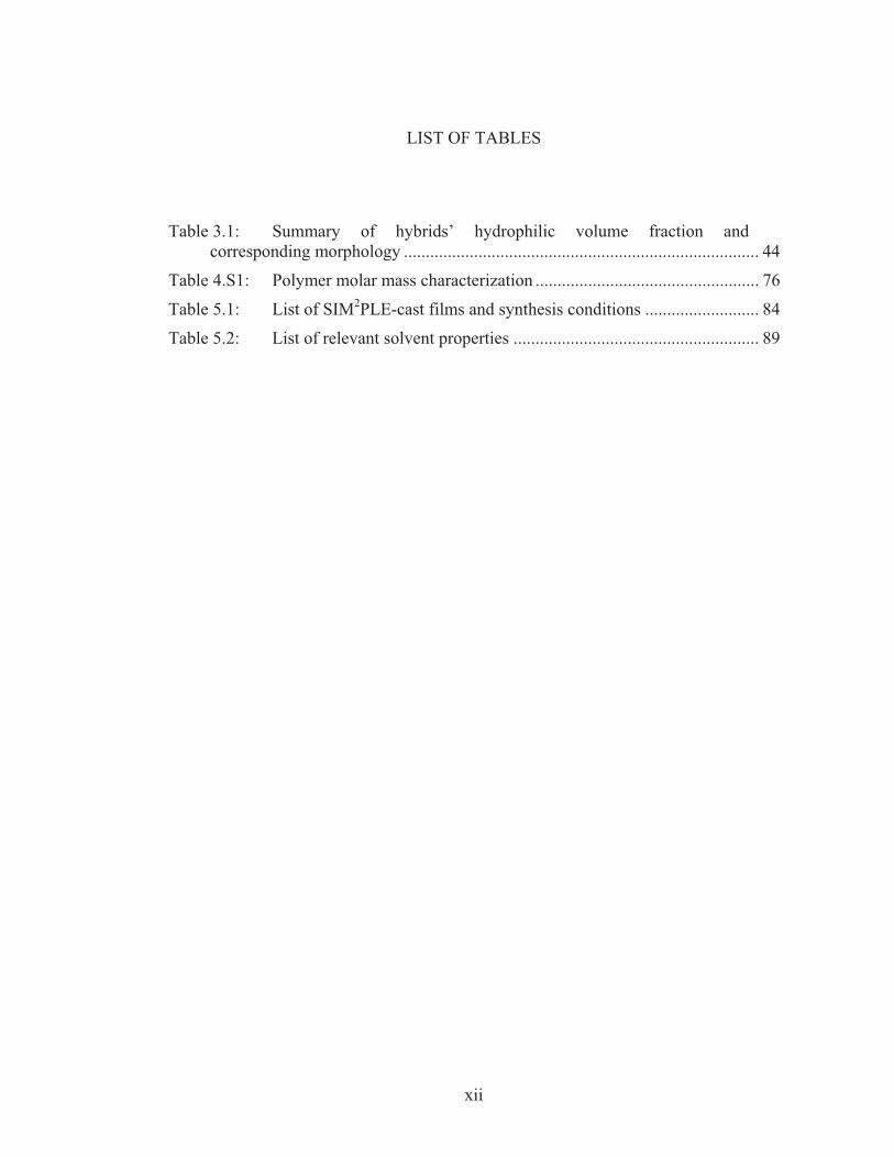
LIST OF TABLES
Table 3.1: Summary of hybrids’ hydrophilic volume fraction and
corresponding morphology ................................................................................. 44
Table 4.S1: Polymer molar mass characterization ................................................... 76
Table 5.1: List of SIM2PLE-cast films and synthesis conditions .......................... 84
Table 5.2: List of relevant solvent properties ........................................................ 89
1
CHAPTER 1
INTRODUCTION
Overview
The role of the nanoscale in materials science and engineering has a long-
standing history, dating back to the production of stained glass using the tunable
plasmonic absorption spectrum of gold nanoparticles1 or hardening of steel by carbon
inclusions,2 to name only a few examples. These discoveries, albeit lacking an
understanding of the underlying mechanisms at their times, are associated with
endeavors to manipulate the bulk intensive properties of materials such as density,
color, modulus, or electrical conductivity. As these properties originate from
interactions of atoms and molecules, designing and characterizing nanoscale structures
near the length scale of these building blocks would enable direct observation and
tuning of structure-property relationships rather than the historical trial-and-error
approaches.
Biologically occurring materials provide a plethora of inspirations for how to
design nanometer and micrometer scale structures for achieving such goals without the
use of energetically costly approaches such as lithography or high-temperature
processing. Many living organisms use abundant elements on earth such as silicon,
calcium, iron and lighter elements, and through directing structures and compositions
at varying length scales ranging from atomic to millimeter-range or larger, synthesize
functional materials such as optically active butterfly wing scales,3 mechanically
2
robust bone,4 or universally adhesive gecko feet.5 In each case, organic templates
made from biological molecules whose information is encoded in DNA form the
building blocks for organization at a larger length scale using local interactions, hence
the name bottom-up self-assembly. Researchers have realized the effectiveness of self-
assembly in synthetic materials and have recently used synthetic structure-directing
agents to guide materials synthesis at nanometer- and micrometer-scales.6
Amphiphilic molecules for nanoscale self-assembly and structure-direction
In this section, we will review two types of structure-directing agents.
Surfactants (short for surface active agents) are a class of materials that lowers the
interfacial energies between distinct phases.7 Surfactants generally consist of
hydrophilic head portions covalently attached to hydrophobic tails. An example of
such a molecule is cetyltrimethylammonium bromide (CTAB), which consists of a
quaternary ammonium head attached to a C16 hydrocarbon tail. When dissolved in
water, CTAB molecules stay as unimolecular species in solution below a certain
concentration called critical micelle concentration (CMC). Above the CMC they
aggregate in water into mesoscale (2-50nm) spherical, hexagonally packed cylindrical,
cubic, or lamellar supramolecular structures. The morphologies formed depend on the
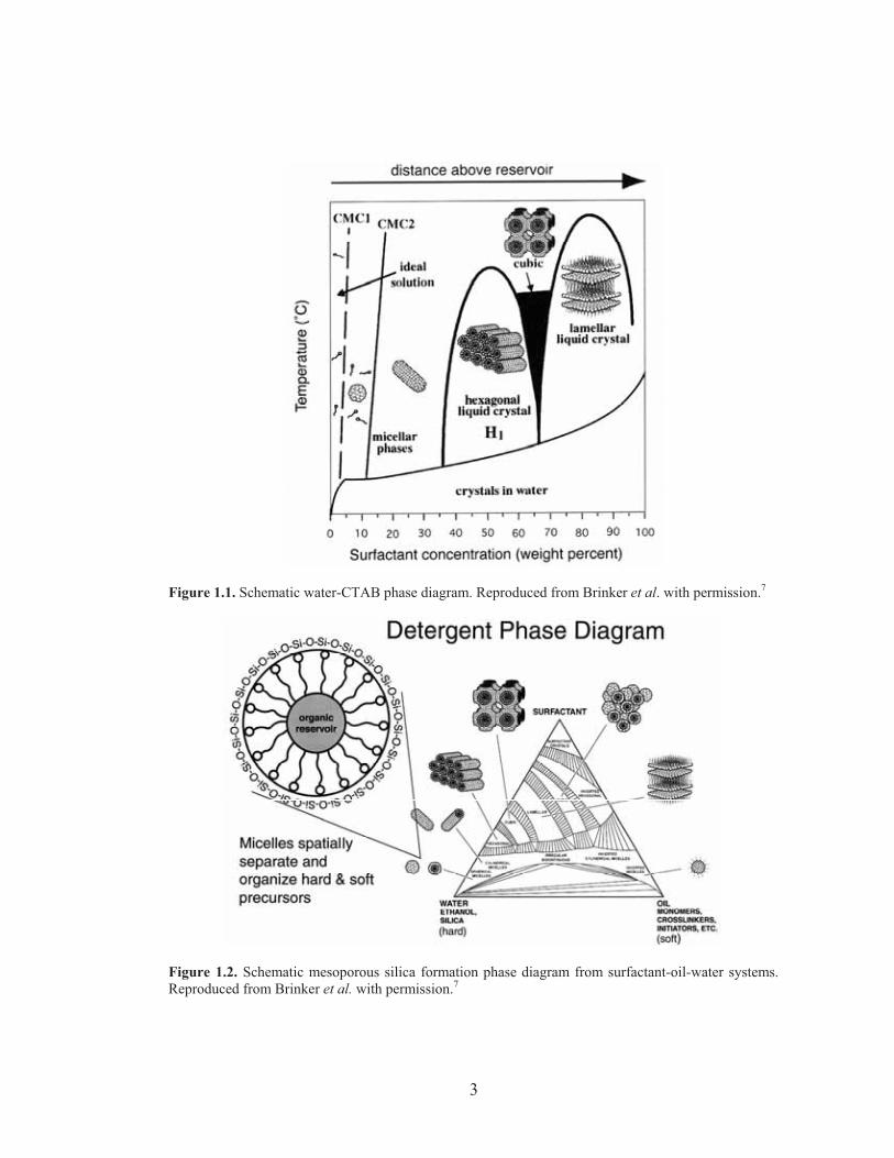
concentration of CTAB, and thus are termed lyotropic liquid crystals (LLCs). Figure
1.1 illustrates the phase diagram of the CTAB-water model system.8 Combination of
surfactant self-assembly with sol-gel processing of ceramics results in LLC-templated
organic-inorganic hybrids (see Figure 1.2),8 in which the inorganic precursors in
solution undergo hydrolysis and condensation to form a sol and then a crosslinked
3
Figure 1.1. Schematic water-CTAB phase diagram. Reproduced from Brinker et al. with permission.7
Figure 1.2. Schematic mesoporous silica formation phase diagram from surfactant-oil-water systems.Reproduced from Brinker et al. with permission.7
4
network (gel) that precipitates out of solution. By tuning environmental parameters
such as temperature, pH, ionic strength and solvents, the kinetics for hydrolysis and
condensation can be adjusted so that the cluster size and dispersibility can be
optimized for structure-directing inorganic species. While the first mention of using
surfactants to co-assemble nanostructured materials dates back to a patent in 1971,9
the first report on mesostructured silica through surfactants appeared in 1990,10
followed by a seminal paper from the Mobil group in 1992.11 Since then, a large
number of research groups have followed the route to produce nanostructured
materials of various compositions,12 form factors (e.g. thin films13 and nanoparticles14),
feature sizes and morphologies.
Block copolymers (BCP) provides another self-assembling building block for
creating nanostructures through bottom-up approaches. Block copolymers consist of
chemically distinct macromolecular blocks that are covalently joined. When these
blocks are amphiphilic, minimization of hydrophilic/hydrophobic interface formation
at the block-junction and the volumetric confinement induce phase separation at the
length scale of the size of the macromolecules, typically 5-50 nm,15, 16 resulting in the
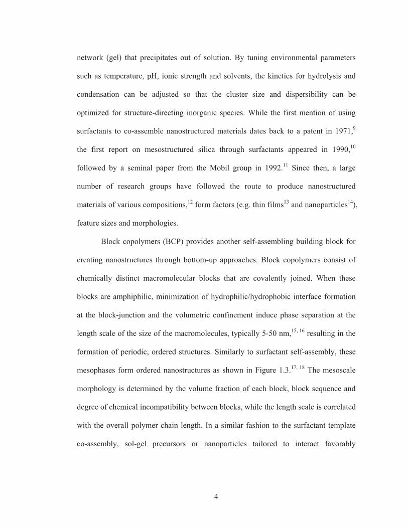
formation of periodic, ordered structures. Similarly to surfactant self-assembly, these
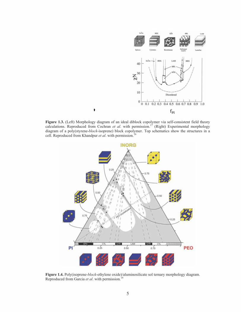
mesophases form ordered nanostructures as shown in Figure 1.3.17, 18 The mesoscale
morphology is determined by the volume fraction of each block, block sequence and
degree of chemical incompatibility between blocks, while the length scale is correlated
with the overall polymer chain length. In a similar fashion to the surfactant template
co-assembly, sol-gel precursors or nanoparticles tailored to interact favorably
5
Figure 1.3. (Left) Morphology diagram of an ideal diblock copolymer via self-consistent field theorycalculations. Reproduced from Cochran et al. with permission.17 (Right) Experimental morphologydiagram of a poly(styrene-block-isoprene) block copolymer. Top schematics show the structures in acell. Reproduced from Khandpur et al. with permission.16
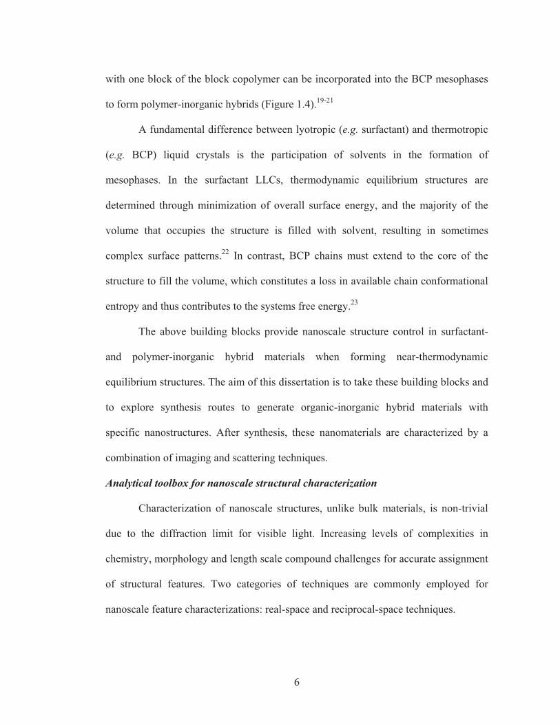
Figure 1.4. Poly(isoprene-block-ethylene oxide)/aluminosilicate sol ternary morphology diagram. Reproduced from Garcia et al. with permission.18
6
with one block of the block copolymer can be incorporated into the BCP mesophases
to form polymer-inorganic hybrids (Figure 1.4).19-21
A fundamental difference between lyotropic (e.g. surfactant) and thermotropic
(e.g. BCP) liquid crystals is the participation of solvents in the formation of
mesophases. In the surfactant LLCs, thermodynamic equilibrium structures are
determined through minimization of overall surface energy, and the majority of the
volume that occupies the structure is filled with solvent, resulting in sometimes
complex surface patterns.22 In contrast, BCP chains must extend to the core of the
structure to fill the volume, which constitutes a loss in available chain conformational
entropy and thus contributes to the systems free energy.23
The above building blocks provide nanoscale structure control in surfactant-
and polymer-inorganic hybrid materials when forming near-thermodynamic
equilibrium structures. The aim of this dissertation is to take these building blocks and
to explore synthesis routes to generate organic-inorganic hybrid materials with
specific nanostructures. After synthesis, these nanomaterials are characterized by a
combination of imaging and scattering techniques.
Analytical toolbox for nanoscale structural characterization
Characterization of nanoscale structures, unlike bulk materials, is non-trivial
due to the diffraction limit for visible light. Increasing levels of complexities in
chemistry, morphology and length scale compound challenges for accurate assignment
of structural features. Two categories of techniques are commonly employed for
nanoscale feature characterizations: real-space and reciprocal-space techniques.
7
In real-space imaging, electromagnetic waves such as high-energy electron
beams or hard x-rays are applied on the sample, and the signals from the sample
(attenuated transmission signals, scattered electron beam signals, or generated
secondary electrons) are collected to reconstruct images of the sample. The short
wavelengths of these beams push the diffraction limit down to sub-nm length scales.
Transmission electron microscopy (TEM), scanning transmission electron microscopy
(STEM), and scanning electron microscopy (SEM) are examples of real-space
imaging techniques. While the information obtained is intuitively easier to understand
than in reciprocal techniques, the fields of view and thus the amount of materials that
can be analyzed with such techniques are usually limited.
On the other hand, high-energy beams can be used to form diffractograms
around the beam center by azimuthally integrating the signal scattering intensity
around the direct beam, which will yield reciprocal space information of the materials.
Such scattering techniques are particularly powerful for materials having long-range
order due to the rise of structure factors, but can be used to measure the ensemble form
factors and correlation length in locally ordered materials as well. Small-angle X-ray
scattering, X-ray diffraction, and selected area electron diffraction are commonly used
to obtain reciprocal space images.
Outline of this dissertation
The outline of this dissertation is as follows:
8
Chapter 1, the current chapter, introduces the readers to the field of
nanostructure synthesis using bottom-up approaches and the characterization methods
for such materials.
Chapter 2 discusses one aspect of structural complexity, namely multiple nano-
sized compartments within a single particle, through synthesis and characterization of
multicompartment mesoporous silica nanoparticles. Surfactant coassembly with sol-
gel silica precursors leads to the synthesis of locally amorphous, but mesoscopically
epitaxially branched silica nanoparticles. The synthesis protocol, characterization, and
proposal for possible mechanisms are detailed.
Chapter 3 discusses another aspect of structural complexity, namely the co-
assembly of ligand-stabilized platinum nanoparticles (Pt NPs) with block copolymers
into nanostructured NP/BCP hybrid materials.
Chapters 4 and 5 discuss another aspect of structural complexity, namely the
synthesis of hierarchically porous nanomaterials. Poly(styrene-block-ethylene oxide)
mixed with oligomeric polyethylene oxides are self-assembled into hierarchical
structures, followed by rinsing of the oligomers with protic solvents to yield
hierarchically porous polymeric scaffolds. Synthesis parameters are explored affecting
the final structures obtained by this synthesis method, termed Spinodal
decomposition-Induced Meso-/Macrophase separation PLus Extraction by rinsing
(SIM2PLE).
Chapter 6 concludes this dissertation by reflecting on the findings of the
various sections in light of possible future directions that could be pursued by
subsequent students.
9
REFERENCES
1. Eichelbaum, M.; Rademann, K.; Muller, R.; Radtke, M.; Riesemeier, H.; Gorner, W., Angew. Chem., Int. Ed. 2005, 44 (48), 7905. 2. Fahlman, B. D., Materials chemistry. 2nd ed.; Springer: Dordrecht ; New York, 2011; p xi, 736 p. 3. Saranathan, V.; Osuji, C. O.; Mochrie, S. G. J.; Noh, H.; Narayanan, S.; Sandy, A.; Dufresne, E. R.; Prum, R. O., Proc. Natl. Acad. Sci. U. S. A. 2010, 107 (26), 11676. 4. Weiner, S.; Wagner, H. D., Annu Rev Mater Sci 1998, 28, 271. 5. Autumn, K.; Liang, Y. A.; Hsieh, S. T.; Zesch, W.; Chan, W. P.; Kenny, T. W.; Fearing, R.; Full, R. J., Nature 2000, 405 (6787), 681. 6. Sanchez, C.; Arribart, H.; Guille, M. M. G., Nat. Mater. 2005, 4 (4), 277. 7. Israelachvili, J. N., Intermolecular and surface forces. 3rd ed.; Academic Press: Burlington, MA, 2011; p xxx, 674 p. 8. Brinker, C. J.; Lu, Y. F.; Sellinger, A.; Fan, H. Y., Adv. Mater. 1999, 11 (7), 579. 9. Chiola, V.; Ritsko, J. E.; Vanderpool, C. D. Process for producing low-bulk density silica. U. S. Patent. 3,556,725, 1971. 10. Yanagisawa, T.; Shimizu, T.; Kuroda, K.; Kato, C., Bull. Chem. Soc. Jpn. 1990, 63 (4), 988. 11. Kresge, C. T.; Leonowicz, M. E.; Roth, W. J.; Vartuli, J. C.; Beck, J. S., Nature 1992, 359 (6397), 710. 12. Huo, Q. S.; Margolese, D. I.; Ciesla, U.; Feng, P. Y.; Gier, T. E.; Sieger, P.; Leon, R.; Petroff, P. M.; Schuth, F.; Stucky, G. D., Nature 1994, 368 (6469), 317. 13. Lu, Y. F.; Ganguli, R.; Drewien, C. A.; Anderson, M. T.; Brinker, C. J.; Gong, W. L.; Guo, Y. X.; Soyez, H.; Dunn, B.; Huang, M. H.; Zink, J. I., Nature 1997, 389 (6649), 364. 14. Grun, M.; Lauer, I.; Unger, K. K., Adv. Mater. 1997, 9 (3), 254. 15. Leibler, L., Macromolecules 1980, 13 (6), 1602. 16. Bates, F. S.; Fredrickson, G. H., Annu. Rev. Phys. Chem. 1990, 41 (1), 525. 17. Floudas, G.; Vazaiou, B.; Schipper, F.; Ulrich, R.; Wiesner, U.; Iatrou, H.; Hadjichristidis, N., Macromolecules 2001, 34 (9), 2947. 18. Cochran, E. W.; Garcia-Cervera, C. J.; Fredrickson, G. H., Macromolecules 2006, 39 (7), 2449. 19. Garcia, B. C.; Kamperman, M.; Ulrich, R.; Jain, A.; Gruner, S. M.; Wiesner, U., Chem. Mater. 2009, 21 (22), 5397. 20. Templin, M.; Franck, A.; DuChesne, A.; Leist, H.; Zhang, Y. M.; Ulrich, R.; Schadler, V.; Wiesner, U., Science 1997, 278 (5344), 1795. 21. Yang, P. D.; Zhao, D. Y.; Margolese, D. I.; Chmelka, B. F.; Stucky, G. D., Nature 1998, 396 (6707), 152. 22. Han, Y.; Zhang, D. L.; Chng, L. L.; Sun, J. L.; Zhao, L.; Zou, X. D.; Ying, J. Y., Nature Chem. 2009, 1 (2), 123. 23. Matsen, M. W.; Bates, F. S., Macromolecules 1996, 29 (23), 7641.
10
CHAPTER 2
MULTICOMPARTMENT MESOPOROUS SILICA NANOPARTICLES WITH
BRANCHED SHAPES FROM SURFACTANT COASSEMBLY*
Abstract
We report a one-pot synthesis method for mesoporous silica nanoparticles
(MSNs) containing both cubic and hexagonally structured compartments within one
particle. These multicompartment MSNs (multi-MSNs) consist of a core with cage-
like cubic mesoporous network morphology and up to four branches with hexagonally
packed cylindrical mesopores epitaxially growing out of the vertices of the cubic core.
Particle structure is investigated using a combination of transmission electron
microscopy and small-angle x-ray scattering while pore characteristics are assessed
using nitrogen sorption measurements. The extent of cylindrical mesostructure growth
is controlled through concentration variation of ethyl acetate in the initial mixture.
Possible nucleation and growth processes leading to this particle morphology are
discussed. Results suggest that the use of epitaxial growth relations may allow
synthesis of mesostructured nanoparticles with well-controlled branched architectures
and shapes.
*Sai, H.; Suteewong, T.; Hovden, R.; Bradbury, M.; Gruner, S. M.; Muller, D.; Wiesner, U. Submitted.
11
Since their discovery,1, 2 mesoporous silica materials have attracted widespread
interest due to the versatility in pore structure, surface chemistry and macroscopic
form (particles, coatings or bulk materials). A variety of mesostructures in mesoporous
silica have been explored, including hexagonal, cage-like cubic, cubic bicontinuous
and platelet ordered structures as well as, most recently, dodecagonal quasicrystalline
structures.3, 4 Mesoporous silica nanoparticles (MSNs) offer a particularly interesting
materials platform owing to the large surface area, pore volume, the ability to
functionalize outer and/or inner surfaces, as well as the tunability of pore geometry
through coassembly or pore swelling agents.5, 6 Inspired by multi-compartment
nanoparticles recently described from self-assembling designer soft macromolecular
materials,7-9 we started to explore the possibility of synthesizing multi-compartment
mesoporous silica nanoparticles (multi-MSNs) based on the existing library of
geometrical variations of the silica pore mesostructure.
The field of solution-grown semiconductor nanoparticle synthesis provides a
clue of how to possibly accomplish such architectures. Here nanoparticles have been
extensively studied with polymorphic atomic structures which are epitaxially attached
at the interface from a core, leading to branched inorganic nanostructures with well-
defined and characteristic shapes such as tetrapods or even dendrimers.10-12 Rather
than epitaxy from atomic structures, mesostructural epitaxy exists in mesoporous
silica, e.g. for various cubic lattices13-16 as well as between nPm3 and 2D hexagonal
lattices.17, 18 The question we will address in the following is how in low molar mass
surfactant coassembly such mesostructural epitaxy can be employed to generate
multicompartment mesoporous silica nanoparticles with branched shapes, in which the
branches exhibit different pore geometries than the core, based on different
mesostructural lattices. Results may open up the translation of concepts from
12
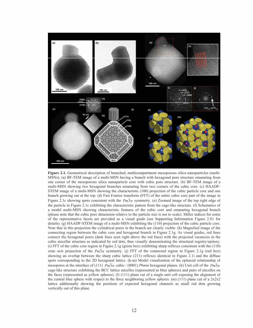
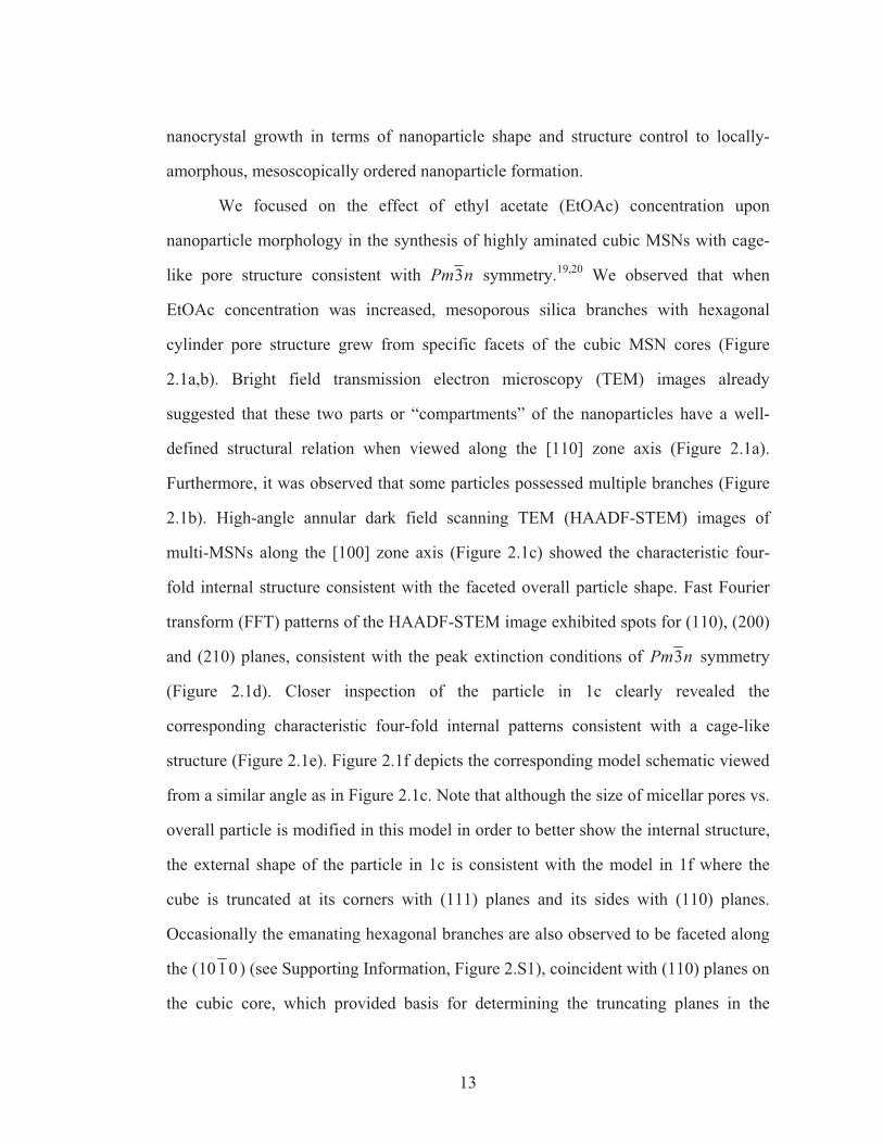
Figure 2.1. Geometrical description of branched, multicompartment mesoporous silica nanoparticles (multi-MSNs). (a) BF-TEM image of a multi-MSN having a branch with hexagonal pore structure emanating fromone corner of the mesoporous silica nanoparticle core with cubic pore structure. (b) BF-TEM image of amulti-MSN showing two hexagonal branches emanating from two corners of the cubic core. (c) HAADF-STEM image of a multi-MSN showing the characteristic (100) projection of the cubic particle core and onebranch growing out at the top. (d) Fast Fourier transform (FFT) of the entire cubic core part of the image inFigure 2.1c showing spots consistent with the nPm3 symmetry. (e) Zoomed image of the top right edge ofthe particle in Figure 2.1c exhibiting the characteristic pattern from the cage-like structure. (f) Schematics ofa model multi-MSN showing characteristic features of the cubic core and emanating hexagonal branch(please note that the cubic pore dimension relative to the particle size is not to scale). Miller indices for someof the representative facets are provided as a visual guide (see Supporting Information Figure 2.S1 fordetails). (g) HAADF-STEM image of a multi-MSN exhibiting the (110) projection of the cubic particle core.Note that in this projection the cylindrical pores in the branch are clearly visible. (h) Magnified image of theconnecting region between the cubic core and hexagonal branch in Figure 2.1g. As visual guides, red linesconnect the hexagonal pores (dark lines seen right above the red lines) with the projected vacancies in thecubic micellar structure as indicated by red dots, thus visually demonstrating the structural registry/epitaxy.(i) FFT of the cubic core region in Figure 2.1g (green box) exhibiting sharp reflexes consistent with the (110)zone axis projection of the nPm3 symmetry. (j) FFT of the connected region in Figure 2.1g (red box)showing an overlap between the sharp cubic lattice (211) reflexes identical to Figure 2.1i and the diffusespots corresponding to the 2D hexagonal lattice. (k-m) Model visualization of the epitaxial relationship ofmesopores at the interface of (111) nPm3 cubic / (0001) P6mm hexagonal planes. (k) Unit cell of the nPm3cage-like structure exhibiting the BCC lattice micelles (represented as blue spheres) and pairs of micelles onthe faces (represented as yellow spheres). (l) (111) plane cut of a single unit cell exposing the alignment ofthe central blue sphere with respect to the three neighboring yellow spheres. (m) (111) plane cut of a 2x2x2lattice additionally showing the positions of expected hexagonal channels as small red dots growingvertically out of this plane.
13
nanocrystal growth in terms of nanoparticle shape and structure control to locally-
amorphous, mesoscopically ordered nanoparticle formation.
We focused on the effect of ethyl acetate (EtOAc) concentration upon
nanoparticle morphology in the synthesis of highly aminated cubic MSNs with cage-
like pore structure consistent with nPm3 symmetry.19,20 We observed that when
EtOAc concentration was increased, mesoporous silica branches with hexagonal
cylinder pore structure grew from specific facets of the cubic MSN cores (Figure
2.1a,b). Bright field transmission electron microscopy (TEM) images already
suggested that these two parts or “compartments” of the nanoparticles have a well-
defined structural relation when viewed along the [110] zone axis (Figure 2.1a).
Furthermore, it was observed that some particles possessed multiple branches (Figure
2.1b). High-angle annular dark field scanning TEM (HAADF-STEM) images of
multi-MSNs along the [100] zone axis (Figure 2.1c) showed the characteristic four-
fold internal structure consistent with the faceted overall particle shape. Fast Fourier
transform (FFT) patterns of the HAADF-STEM image exhibited spots for (110), (200)
and (210) planes, consistent with the peak extinction conditions of nPm3 symmetry
(Figure 2.1d). Closer inspection of the particle in 1c clearly revealed the
corresponding characteristic four-fold internal patterns consistent with a cage-like
structure (Figure 2.1e). Figure 2.1f depicts the corresponding model schematic viewed
from a similar angle as in Figure 2.1c. Note that although the size of micellar pores vs.
overall particle is modified in this model in order to better show the internal structure,
the external shape of the particle in 1c is consistent with the model in 1f where the
cube is truncated at its corners with (111) planes and its sides with (110) planes.
Occasionally the emanating hexagonal branches are also observed to be faceted along
the ( 0110 ) (see Supporting Information, Figure 2.S1), coincident with (110) planes on
the cubic core, which provided basis for determining the truncating planes in the
14
model. When HAADF-STEM images were obtained along the [110] zone axis (Figure
2.1g) of the cubic center, the internal linear pore structure of the hexagonal branch was
clearly observed. Figure 2.1h shows a magnified image of the connecting region
between the cubic core and the branch. Red lines represent extensions of the
cylindrical pores of the hexagonal branch and are in registry with the micellar pores of
the cubic core depicted as red dots, visually supporting an epitaxial relationship
between the mesostructures of the two compartments. While FFT of the cubic core
region showed spots corresponding to the nPm3 peak positions with the (110) zone
axis (Figure 2.1i), FFT of the connected region showed an overlap of relatively sharp
(211) spots from the cubic lattice and relatively diffuse (10) spots from the 2D
hexagonal lattice, also consistent with an epitaxial relationship between the two
structures (Figure 2.1j). This epitaxial relationship can be modeled by a sphere-to-rod
transition of micelles as illustrated in Figure 2.1k-m. The nPm3 cage-like cubic
structure is composed of a body-centered cubic arrangement of micelles plus pairs of
micelles on each cubic face (Figure 2.1k). Sectioning the unit cell at the (111) plane,
each blue micelle resides on top of a set of three yellow micelles, making a locally
layered order (Figure 2.1l). Figure 2.1m shows the top-view schematic of where the
2D hexagonal channels are placed with respect to the (111) cubic planes: the
hexagonal lattice of the blue micelles are in registry with the hexagonally ordered
channels, consistent with the observations made in Figure 2.1h as highlighted by the
red lines and dots.
By increasing the concentration of ethyl acetate in the initial mixture, the
relative amount of hexagonal versus cubic mesostructure can be controlled (Figure
2.2). Low magnification TEM images of MSNs synthesized from EtOAc
concentrations of 91 mM, 274 mM, and 457 mM, respectively (Figure 2.2a,d,g) show
hexagonally ordered branches only at elevated concentrations (Figure 2.2a only shows
15
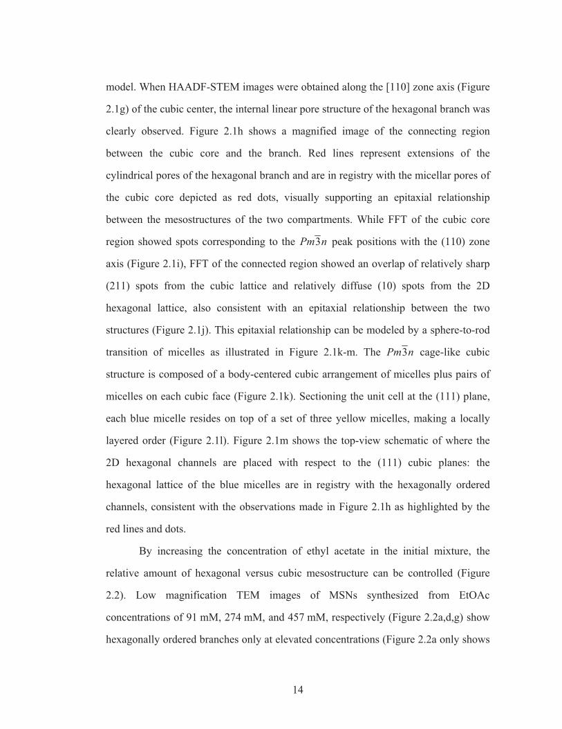
Figure 2.2. TEM images at two different magnifications (a,d,g and b,e,h) and corresponding SAXSpatterns (c,f,i) of aminated MSNs prepared from 91 mM (a-c), 274 mM (d-f) and 457 mM (g-i) ethylacetate concentration. In the SAXS patterns expected peak positions from cubic and hexagonal latticesare indicated with solid and dotted lines, respectively. Data for 91 mM ethyl acetate is adapted fromRef. 19.
200 nm 200 nm200 nm 200 nm 200 nm
2000 nm 2000 nm 2000 nm
0 0.1 0.2 0.3 0.4 0 0.1 0.2 0.3 0.4 0 0.1 0.2 0.3 0.4
b
a
c f
e
d
i
h
g
q / Å-1q / Å-1q / Å-1
16
cubic MSNs). The length of these hexagonally ordered branches increases with
increasing EtOAc concentration (compare Figures 2d and g). In Figure 2.2d the
majority of multi-MSNs from 274 mM EtOAc has short hexagonal branches with
diameters equal to or smaller than the cubic core size. In the 457 mM sample, these
branches grow to rods as long as 2 microns, often in a non-straight fashion (Figure
2.2g). Higher magnification images show that the 274 mM nanoparticles (Figure 2.2e)
consist of a hexagonal branch attached to a core with cage-like cubic structure
identical to the cubic MSN shown in Figure 2.2b. At 457 mM (Figure 2.2h), for most
of the rods we could not find a cubic core portion, suggesting structural transformation
from cubic to hexagonal mesostructure. Small angle X-ray scattering patterns (Figures
2c,f,i) of these samples averaging over macroscopic material volumes corroborate the
more local TEM observations in that the relative intensities of the peaks consistent
with P6mm 2D hexagonal symmetry increase at the expense of those consistent with
nPm3 symmetry: The cubic MSN sample from 91 mM EtOAc shows reflections
consistent with nPm3 symmetry and 9.65 nm unit cell size (Figure 2.2c).19 At 274
mM EtOAc a superposition is observed of reflections consistent with 2D hexagonal
symmetry and 4.80 nm unit cell size with reflections consistent with nPm3 symmetry
and 10.5 nm unit cell size (Figure 2.2f). The (211) reflection for the cubic lattice
coincides closely with the (10) reflection for the hexagonal lattice, with lattice
mismatch of ~3%, further suggesting an epitaxial relation between the two lattices.
The pore-to-pore spacing for the hexagonal branches/compartments in the 274mM
multi-MSNs are 8 % larger than those for purely hexagonal MSNs synthesized in the
absence of APTES and 3-4 % larger than those synthesized in the presence of varying
amounts of APTES (see Supporting Information, Figure 2.S2).20, 21 On the other hand,
the (211) spacing of the cubic core is 4.95 nm, indicating that the 2D hexagonal lattice
is stretched to accommodate for the lattice mismatch. At 457 mM EtOAc reflections
17
consistent with nPm3 have almost disappeared, leaving mostly those consistent with
2D hexagonal symmetry and 4.86 nm pore-to-pore spacing (Figure 2.2i). The increase
in spacing as a function of EtOAc concentration for both cubic and hexagonal
structures (as shown in Figure 2.S2) is likely associated with swelling of the
hydrophobic micelle cores with EtOAc, vide infra.
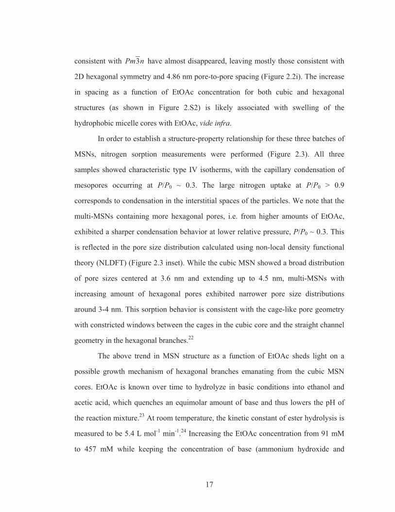
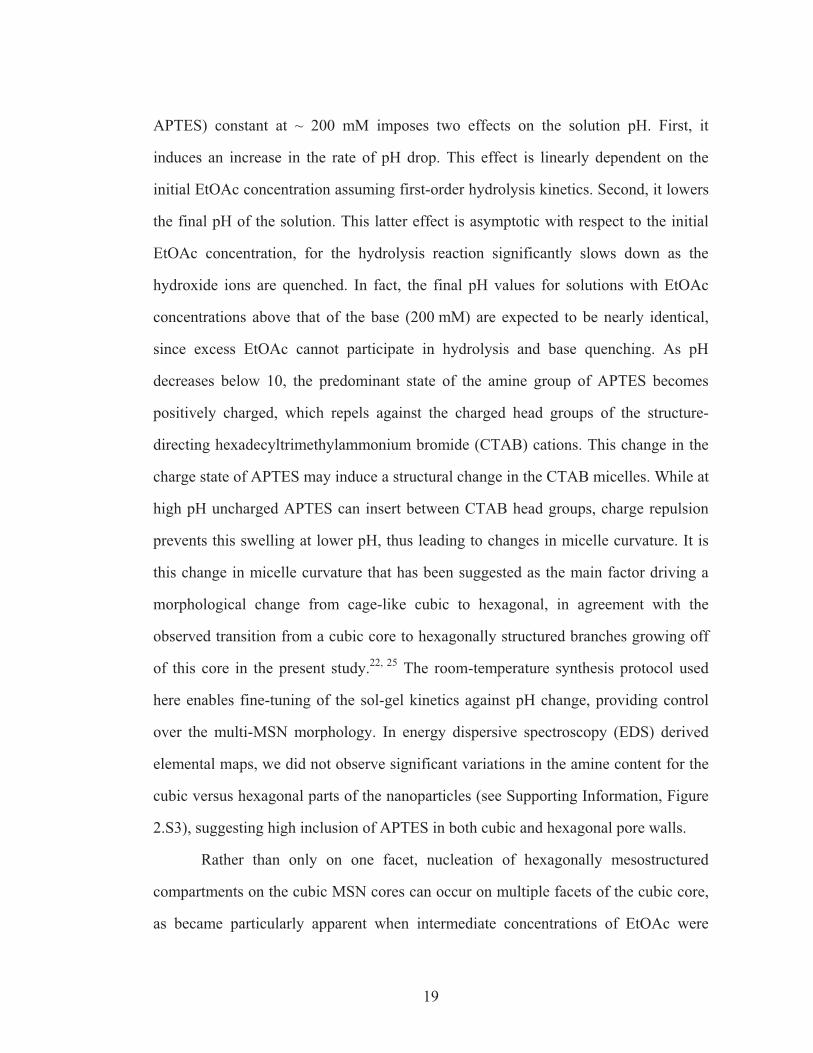
In order to establish a structure-property relationship for these three batches of
MSNs, nitrogen sorption measurements were performed (Figure 2.3). All three
samples showed characteristic type IV isotherms, with the capillary condensation of
mesopores occurring at P/P0 ~ 0.3. The large nitrogen uptake at P/P0 > 0.9
corresponds to condensation in the interstitial spaces of the particles. We note that the
multi-MSNs containing more hexagonal pores, i.e. from higher amounts of EtOAc,
exhibited a sharper condensation behavior at lower relative pressure, P/P0 ~ 0.3. This
is reflected in the pore size distribution calculated using non-local density functional
theory (NLDFT) (Figure 2.3 inset). While the cubic MSN showed a broad distribution
of pore sizes centered at 3.6 nm and extending up to 4.5 nm, multi-MSNs with
increasing amount of hexagonal pores exhibited narrower pore size distributions
around 3-4 nm. This sorption behavior is consistent with the cage-like pore geometry
with constricted windows between the cages in the cubic core and the straight channel
geometry in the hexagonal branches.22
The above trend in MSN structure as a function of EtOAc sheds light on a
possible growth mechanism of hexagonal branches emanating from the cubic MSN
cores. EtOAc is known over time to hydrolyze in basic conditions into ethanol and
acetic acid, which quenches an equimolar amount of base and thus lowers the pH of
the reaction mixture.23 At room temperature, the kinetic constant of ester hydrolysis is
measured to be 5.4 L mol-1 min-1.24 Increasing the EtOAc concentration from 91 mM
to 457 mM while keeping the concentration of base (ammonium hydroxide and
18
Figure 2.3. Nitrogen sorption isotherms of MSNs synthesized with varying EtOAc concentrations.Isotherms for 274 mM and 457 mM multi-MSNs are offset along the y-axis by 15 and 30 mmol/g,respectively. The inset shows pore size distributions obtained from non-local density functional theory(NLDFT) calculations based on the respective absorption branches. The models on the right provide adirect comparison of the pore structures of hexagonal and cubic lattices.
19
APTES) constant at ~ 200 mM imposes two effects on the solution pH. First, it
induces an increase in the rate of pH drop. This effect is linearly dependent on the
initial EtOAc concentration assuming first-order hydrolysis kinetics. Second, it lowers
the final pH of the solution. This latter effect is asymptotic with respect to the initial
EtOAc concentration, for the hydrolysis reaction significantly slows down as the
hydroxide ions are quenched. In fact, the final pH values for solutions with EtOAc
concentrations above that of the base (200 mM) are expected to be nearly identical,
since excess EtOAc cannot participate in hydrolysis and base quenching. As pH
decreases below 10, the predominant state of the amine group of APTES becomes
positively charged, which repels against the charged head groups of the structure-
directing hexadecyltrimethylammonium bromide (CTAB) cations. This change in the
charge state of APTES may induce a structural change in the CTAB micelles. While at
high pH uncharged APTES can insert between CTAB head groups, charge repulsion
prevents this swelling at lower pH, thus leading to changes in micelle curvature. It is
this change in micelle curvature that has been suggested as the main factor driving a
morphological change from cage-like cubic to hexagonal, in agreement with the
observed transition from a cubic core to hexagonally structured branches growing off
of this core in the present study.22, 25 The room-temperature synthesis protocol used
here enables fine-tuning of the sol-gel kinetics against pH change, providing control
over the multi-MSN morphology. In energy dispersive spectroscopy (EDS) derived
elemental maps, we did not observe significant variations in the amine content for the
cubic versus hexagonal parts of the nanoparticles (see Supporting Information, Figure
2.S3), suggesting high inclusion of APTES in both cubic and hexagonal pore walls.
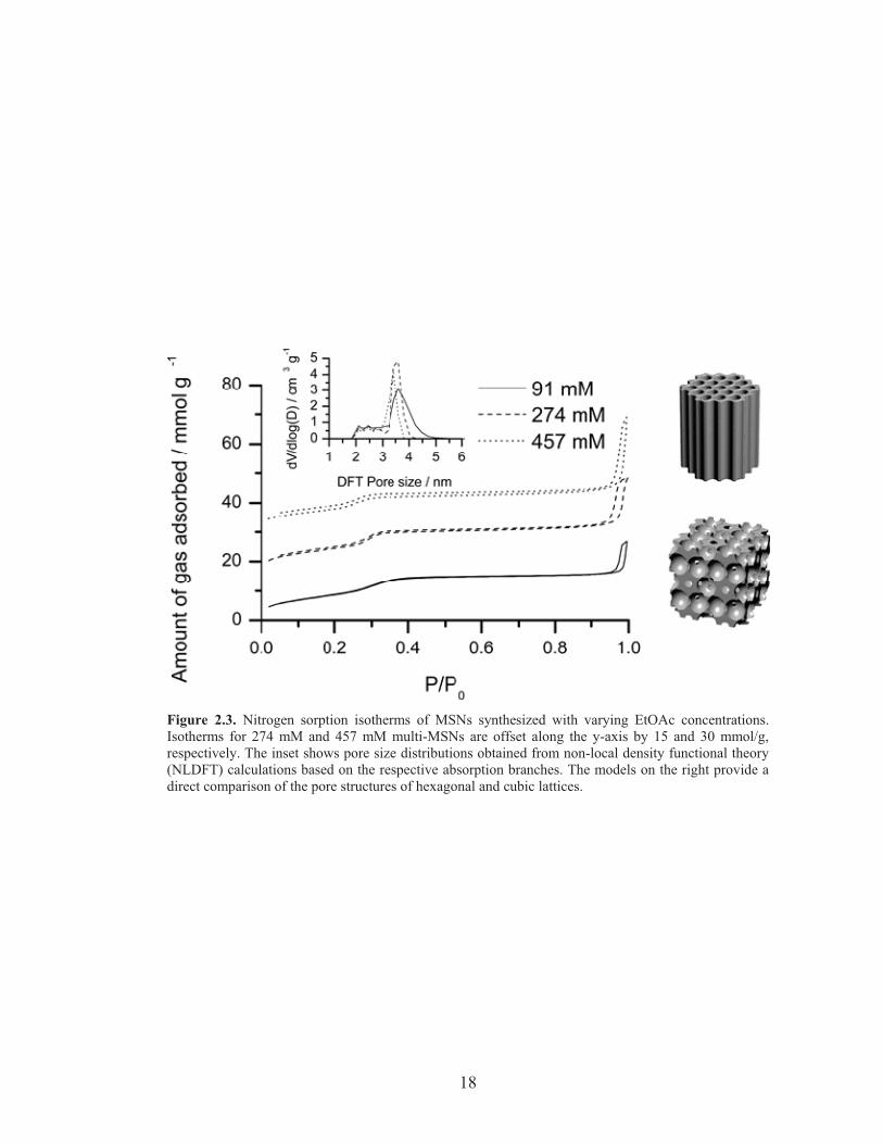
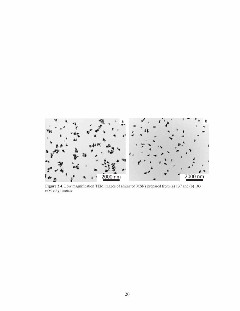
Rather than only on one facet, nucleation of hexagonally mesostructured
compartments on the cubic MSN cores can occur on multiple facets of the cubic core,
as became particularly apparent when intermediate concentrations of EtOAc were
20
2000 nm 2000 nm
a b
Figure 2.4. Low magnification TEM images of aminated MSNs prepared from (a) 137 and (b) 183 mM ethyl acetate.
21
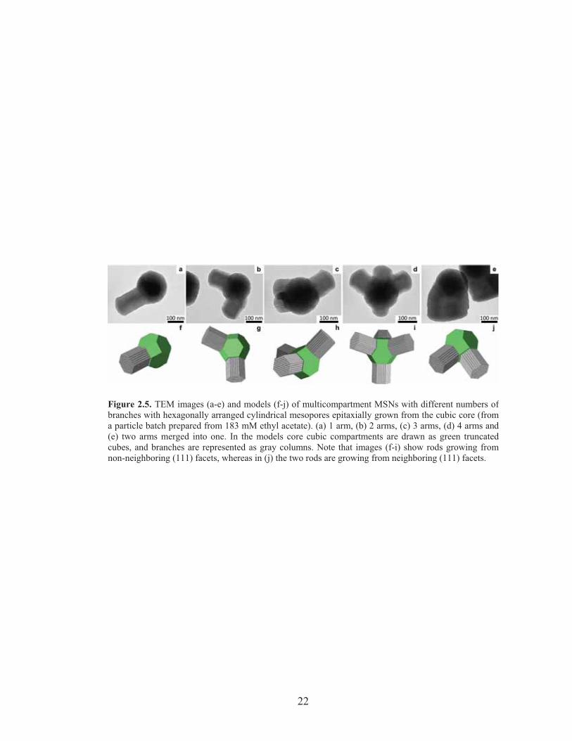
employed. While for EtOAc concentrations of 137 mM and 183 mM most particles
still only showed one hexagonal branch per cubic core, a fraction had one, two, three
and even four branches (Figure 2.4a,b). Close TEM examination of these multi-MSNs
revealed that the angles at which the hexagonally structured branches grow were
consistent with models where hexagonal branches grow in <111> directions off of the
cubic core, further consistent with the epitaxial relationship (compare TEM images
with corresponding models in Figure 2.5a-d and f-i, respectively). Interestingly, no
MSN with a number of branches larger than four was observed in our samples, while
we did observe some multi-MSNs in which hexagonal rods that grew in two distinct
directions merged into one rod with a large diameter (compare TEM image/model in
Figure 2.5e/j). On a truncated cubic structure, there are eight (111) equivalent surfaces
corresponding to the number of cube vertices, giving eight equivalent sites for
hexagonal branches to form and grow. As a particular branch grows, it may deplete
the available silica in its direct vicinity, thus preventing growth of another branch next
to it. This is one possible explanation why the vast majority of observed branches had
grown on non-nearest (111) core surfaces and why the maximum number of branches
observed was only four. We further hypothesize that in the case two nearest
neighboring sites nucleate hexagonal branches, geometrical crowding joins the
neighboring nuclei as they grow. Such merging and overgrowth of hexagonal rods also
reduces the number of rods per particle and increases the rod diameter compared to the
core particle size. This may be what lead to the observed structures in the 457 mM
EtOAc sample (Figure 2.2g).
In summary, we have demonstrated the successful synthesis of branched
multicompartment MSNs containing a cage-like cubic core and branches growing off
of the core with hexagonal cylindrical pores. Using a combination of TEM and SAXS
experiments an epitaxial relation between the mesostructures of the two compartments
22
Figure 2.5. TEM images (a-e) and models (f-j) of multicompartment MSNs with different numbers ofbranches with hexagonally arranged cylindrical mesopores epitaxially grown from the cubic core (froma particle batch prepared from 183 mM ethyl acetate). (a) 1 arm, (b) 2 arms, (c) 3 arms, (d) 4 arms and(e) two arms merged into one. In the models core cubic compartments are drawn as green truncatedcubes, and branches are represented as gray columns. Note that images (f-i) show rods growing fromnon-neighboring (111) facets, whereas in (j) the two rods are growing from neighboring (111) facets.
23
was evidenced. With the help of nitrogen sorption measurements a correlation
between the specific structure of the nanoparticles and their porosity was established.
A simple parameter, namely the ethyl acetate (EtOAc) concentration in the starting
synthesis mixture governed the overall fraction of nanoparticle silica with hexagonal
cylindrical morphology. Based on our findings a mechanism for the growth of these
multicompartment nanoparticles was suggested. The results described here suggest
that in analogy to recent developments in nanocrystal synthesis, the use of epitaxial
growth relations in the synthesis of locally-amorphous, mesoscopically ordered (silica)
nanoparticles may allow access to more complex yet precisely controlled shapes and
compositions as well as to assemblies of these nanoparticles with carefully controlled
interconnections.
Acknowledgment
This work was supported by the National Science Foundation (NSF, DMR-
1104773), and by the U.S. Department of Homeland Security under Cooperative
Agreement Number “2009-ST-108-LR0004”. This work made use of the TEM facility
of the Cornell Center for Materials Research (CCMR) with support from the National
Science Foundation Materials Research Science and Engineering Centers (MRSEC)
program (DMR-1120296), and the Cornell High Energy Synchrotron Source
(CHESS), which is supported by the NSF and the National Institutes of
Health/National Institute of General Medical Sciences under NSF award DMR-
0225180. T.S. is grateful for a Thai Government Scholarship under the Ministry of
Science and Technology.
24
REFERENCES
1. Yanagisawa, T.; Shimizu, T.; Kuroda, K.; Kato, C., Bull. Chem. Soc. Jpn. 1990, 63 (4), 988. 2. Kresge, C. T.; Leonowicz, M. E.; Roth, W. J.; Vartuli, J. C.; Beck, J. S., Nature 1992, 359 (6397), 710. 3. Hoffmann, F.; Cornelius, M.; Morell, J.; Froba, M., Angew. Chem. Int. Ed. 2006, 45 (20), 3216. 4. Xiao, C. H.; Fujita, N.; Miyasaka, K.; Sakamoto, Y.; Terasaki, O., Nature 2012, 487 (7407), 349. 5. Vallet-Regi, M.; Balas, F.; Arcos, D., Angew. Chem. Int. Ed. 2007, 46 (40), 7548. 6. Slowing, II; Vivero-Escoto, J. L.; Wu, C. W.; Lin, V. S. Y., Adv. Drug Delivery Rev. 2008, 60 (11), 1278. 7. Li, Z. B.; Kesselman, E.; Talmon, Y.; Hillmyer, M. A.; Lodge, T. P., Science 2004, 306 (5693), 98. 8. Cui, H. G.; Chen, Z. Y.; Zhong, S.; Wooley, K. L.; Pochan, D. J., Science 2007, 317 (5838), 647. 9. Chandrawati, R.; van Koeverden, M. P.; Lomas, H.; Caruso, F., J. Phys. Chem. Lett. 2011, 2 (20), 2639. 10. Manna, L.; Milliron, D. J.; Meisel, A.; Scher, E. C.; Alivisatos, A. P., Nat. Mater. 2003, 2 (6), 382. 11. Yin, Y.; Alivisatos, A. P., Nature 2005, 437 (7059), 664. 12. Talapin, D. V.; Nelson, J. H.; Shevchenko, E. V.; Aloni, S.; Sadtler, B.; Alivisatos, A. P., Nano Lett. 2007, 7 (10), 2951. 13. Srinivasu, P.; Lim, S.; Kubota, Y.; Tatsumi, T., Catal. Today 2006, 111 (3-4), 379. 14. Han, L.; Sakamoto, Y.; Che, S.; Terasaki, O., Chem. Eur. J. 2009, 15 (12), 2818. 15. Atluri, R.; Bacsik, Z.; Hedin, N.; Garcia-Bennett, A. E., Microporous Mesoporous Mater. 2010, 133 (1-3), 27. 16. Han, L.; Miyasaka, K.; Terasaki, O.; Che, S. N., J. Am. Chem. Soc. 2011, 133 (30), 11524. 17. Che, S. N.; Kamiya, S.; Terasaki, O.; Tatsumi, T., J. Am. Chem. Soc. 2001, 123 (48), 12089. 18. Kamiya, S.; Tanaka, H.; Che, S.; Tatsumi, T.; Terasaki, O., Solid State Sci. 2003, 5 (1), 197. 19. Suteewong, T.; Sai, H.; Cohen, R.; Wang, S.; Bradbury, M.; Baird, B.; Gruner, S. M.; Wiesner, U., J. Am. Chem. Soc. 2011, 133 (2), 172. 20. Suteewong, T.; Sai, H.; Bradbury, M.; Estroff, L. A.; Gruner, S. M.; Wiesner, U., Chem. Mater., 2012, 24 (20), 3895. 21. Suteewong, T.; Sai, H.; Lee, J.; Bradbury, M.; Hyeon, T.; Gruner, S. M.; Wiesner, U., J. Mater. Chem. 2010, 20 (36), 7807. 22. Atluri, R.; Sakamoto, Y.; Garcia-Bennettt, A. E., Langmuir 2009, 25 (5), 3189.
25
23. Schulz-Ekloff, G.; Rathousky, J.; Zukal, A., Int. J. Inorg. Mater. 1999, 1 (1), 97. 24. Dittert, L. W.; Higuchi, T., J. Pharm. Sci. 1963, 52 (9), 852. 25. Ogura, M.; Miyoshi, H.; Naik, S. P.; Okubo, T., J. Am. Chem. Soc. 2004, 126 (35), 10937.
26
APPENDIX: SUPPLEMENTARY MATERIALS
Experimental Methods
Materials
Hexadecyltrimethylammonium bromide (CTAB, approx. 99%), ethyl acetate
(EtOAc, ACS grade), tetraethyl orthosilicate (TEOS, �99%, GC), (3-
aminopropyl)triethoxysilane (APTES, > 95%), ammonium hydroxide (NH4OH, 29%),
acetic acid (glacial), hydrochloric acid (36.5-38%), ethanol (absolute, anhydrous) and
deionized water (Milli-Q, 18.2 M�-cm) were used as obtained without further
purification.
Synthesis of multicompartment mesoporous silica nanoparticles (multi-MSNs)
Multicompartment mesoporous silica nanoparticles (multi-MSNs) were
prepared by increasing the ethyl acetate (EtOAc) concentration of the highly aminated
cubic MSNs reported in a previous publication.1,2 The volumetric ratio in milliliters of
chemicals used in the synthesis of cubic MSNs was 1 CTAB (aq):0.045 TEOS:0.055
APTES:0.54 NH4OH:0.176 EtOAc:27.38 H2O. For multi-MSNs, EtOAc volume per
CTAB (aq) was varied from 0.264 for 137 mM to 0.880 for 457 mM. CTAB solution
was gently stirred in a container to which H2O, EtOAc, NH4OH, and mixed silanes
were added in this order. We note that after EtOAc addition, the mixture was left
stirring for a few minutes to let the EtOAc dissolve before adding the rest of the
reagents. Five minutes after silane addition was complete, H2O (7.98 v/v CTABaq)
was added and the mixture was left stirring for 24 hours. On completion of the
reaction, samples were neutralized with 2 M HClaq, and the MSNs were cleaned of
27
incorporated CTAB micelles with acetic acid as reported previously.1,2 The particles
were redispersed in absolute ethanol or kept dry for storage to prevent further
hydrolysis.
In order to determine the surface amine content on the multi-MSN using
elemental analysis by energy-dispersive x-ray spectroscopy (EDS), iridium (III)
chloride hydrate was used as a contrasting agent according to previous literature.3
Characterization
Bright-field transmission electron microscopy (TEM) images were obtained on
a Tecnai T12 Spirit microscope, equipped with a LaB6 source and a SIS Megaview III
CCD camera and running at an acceleration voltage of 120 kV. High-angle annular
dark field scanning transmission electron microscopy (HAADF-STEM) images and
EDS elemental maps were acquired on a Tecnai F20 microscope operating at an
acceleration voltage of 200 kV. Hanning-filtered Fast Fourier transform (FFT) images
were calculated and analyzed in the Electron Direct Methods (EDM) software suite,
version 3.0.
Small-angle x-ray scattering (SAXS) patterns of surfactant-extracted, dried
MSN samples were obtained on a home-built rotating anode beamline as well as at the
G1 station in Cornell High Energy Synchrotron Source (CHESS). 1,2 For the rotating
anode setup, a flight path of 15 cm was used with the CuK� source, while a 40cm
flight path with 10 keV x-ray was used in CHESS G1. Two-dimensional patterns
obtained on a phosphor-optical fiber coupled CCD were azimuthally integrated to
generate the 1D SAXS patterns in the MATLAB software suite.
28
Nitrogen sorption experiments were performed on a Micromeritics ASAP2020
instrument. Around 10 mg of the samples were degassed at 110-120 °C under vacuum
overnight prior to the measurements. Acquired isotherms were analyzed for pore size
distribution using the non-local density functional theory (NLDFT) package using a
cylindrical geometry and Tarazona’s density functional model.
REFERENCES
1. Suteewong, T.; Sai, H.; Cohen, R.; Wang, S.; Bradbury, M.; Baird, B.; Gruner, S. M.; Wiesner, U., J. Am. Chem. Soc. 2011, 133 (2), 172. 2. Suteewong, T.; Sai, H.; Bradbury, M.; Estroff, L. A.; Gruner, S. M.; Wiesner, U., Chem. Mater., 2012, 24 (20), 3895. 3. Kecht, J.; Schlossbauer, A.; Bein, T., Chem. Mater. 2008, 20 (23), 7207.
29
Supplementary Figures
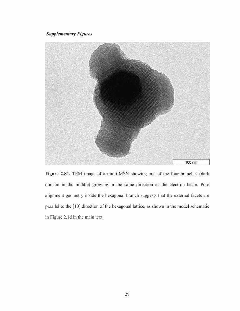
Figure 2.S1. TEM image of a multi-MSN showing one of the four branches (dark
domain in the middle) growing in the same direction as the electron beam. Pore
alignment geometry inside the hexagonal branch suggests that the external facets are
parallel to the [10] direction of the hexagonal lattice, as shown in the model schematic
in Figure 2.1d in the main text.
30
0 10 20 30 40 50 604.4
4.5
4.6
4.7
4.8
4.9
5.0
Spacings
(nm)
APTES content (%)
: Pm3n cubic (211)
: Hexagonal pore-to-pore
[EtOAc] = 274 mM
[EtOAc] = 91 mM
[EtOAc] = 274 mM
[EtOAc] = 457 mM
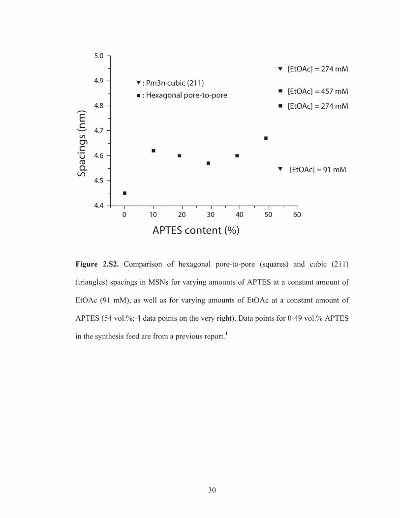
Figure 2.S2. Comparison of hexagonal pore-to-pore (squares) and cubic (211)
(triangles) spacings in MSNs for varying amounts of APTES at a constant amount of
EtOAc (91 mM), as well as for varying amounts of EtOAc at a constant amount of
APTES (54 vol.%; 4 data points on the very right). Data points for 0-49 vol.% APTES
in the synthesis feed are from a previous report.1

31
Figure 2.S3. EDS-derived elemental mapping profiles on a line slice of an iridium-
stained multi-MSN (see Supporting Information, Experimental Methods). Inset shows
the contour along which the spectra were taken. Note that the Si/Ir ratio difference
between the hexagonal branch and the cubic center is insignificant, indicating that the
amine content in the hexagonal branch and cubic core is the same.
32
CHAPTER 3
METAL NANOPARTICLE/BLOCK COPOLYMER COMPOSITE ASSEMBLY
AND DISASSEMBLY*
Abstract
Ligand-stabilized platinum nanoparticles (Pt NPs) were self-assembled with
poly(isoprene-block-dimethylaminoethyl methacrylate) (PI-b-PDMAEMA) block
copolymers to generate organic-inorganic hybrid materials. High loadings of NPs in
hybrids were achieved through usage of N,N-di-(2-(allyloxy)ethyl)-N-3-
mercaptopropyl-N-3-methylammonium chloride as the ligand, which provided high
solubility of NPs in various solvents as well as high affinity to PDMAEMA. From NP
synthesis, existence of sub-1 nm Pt NPs was confirmed by high-angle annular dark
field scanning transmission electron microscopy (HAADF-STEM) images.
Estimations of the Pt NP ligand head group density based on HAADF-STEM images
and thermogravimetric analysis (TGA) data yielded results comparable to what has
been found for alkanethiol self-assembled monolayers (SAMs) on flat Pt {111}
surfaces. Changing the volume fraction of Pt NPs in block copolymer-NP composites
yielded hybrids with spherical micellar, wormlike micellar, lamellar and inverse
hexagonal morphologies. Disassembly of hybrids with spherical, wormlike micellar,
and lamellar morphologies generated isolated metal-NP based nano-spheres, cylinders
and sheets, respectively. Results suggest the existence of powerful design criteria for
the formation of metal-based nanostructures from designer blocked macromolecules.
* Li, Z.; Sai, H.; Warren, S. C.; Kamperman, M. K.; Arora, H.; Gruner, S. M.; Wiesner, U. Chem. Mater. 2009, 21 (23), 5578–5584.
33
Introduction
Block copolymer (BCP) self-assembly is considered a powerful route to
achieve nanoscale (2-50 nm) materials because of its ability to form various periodic
structures with tunable length scale.1-3 BCPs have been used as structure directing
agents to incorporate different loadings of functional inorganic species into select
blocks of BCPs, resulting in ordered nanostructured organic-inorganic hybrid
materials.4-6 BCPs in hybrids with high inorganic loading can be removed by
chemical, photochemical and/or thermal treatments without collapse of the structures,
resulting in nanoporous functional materials. This methodology has been successfully
applied to various inorganic systems, such as aluminosilicates,6 orthosilicates,7-9
transition metal oxides10,11 and non-oxide ceramics.12,13 Despite the achievements in
the field, synthesizing ordered nanostructured metal hybrids and metals thereof using
BCPs remains challenging due to high surface energies of metals. To date, mainly two
approaches are being utilized: the first involves in-situ metal nanoparticles (NP)
synthesis, where BCPs are loaded or swollen by metal precursors prior or after
microphase separation, and a subsequent reducing step is applied to transform the
metal precursors into metal NPs.14-19 Different metals (e.g. Au, Pt, Pd, Ag) and
polymers (e.g. poly(styrene-block-acrylic acid) (PS-b-PAA), poly(styrene-block-2-
vinylpyridine) (PS-b-P2VP)) have been used, proving the generality of this approach.
Although in-situ methods are suitable for thin film applications, loading of the metals
is limited by the diffusion of the reagents when applying to bulk materials with larger
thickness. The second approach involves ex-situ metal NP synthesis. Preformed metal
NPs are self-assembled with block copolymers where the NPs are stabilized with
tailored surface ligands or functional groups which render them compatible with only
one block of the block copolymer.20-26 Extensive studies of this method have been
performed in the last nearly two decades both in thin films and in the bulk. For
34
example, Au NPs stabilized with alkanethiol groups localized at the interface between
a symmetric poly(styrene-block-ethylene-co-propylene) (PS-b-PEP) has been reported
by Bockstaller et al.20 Kim et al. studied PS-coated Au NPs self-assembled with PS-b-
P2VP. They found that the addition of NPs increased the effective volume fraction of
the PS block and thus induced a lamellar-to-cylindrical phase transition.21 They also
studied the effect of ligand head group density on NPs/polymer interaction.22,23
Finally, more recently some of us reported the assembly of metal NPs in block
copolymer brushes in which NP-BCP interactions are tuned, likewise, by ligand head
density.26
Most of the work on BCP/metal NP self-assembly has focused on the dilute
nanoparticle regime, where the NPs only comprise a small volume fraction of the
hybrid material. Achieving hybrid synthesis in the dense nanoparticle regime27 where
NPs comprise the majority volume fraction will provide access to nanostructured
organic-metal hybrid materials, as well as to nanoporous metals.19,28,29 It has been
reported in several BCP/NP systems that when the volume fraction of NPs increases,
controlled microphase separation of the BCP was disrupted.30,31 The observed
macrophase separation could arise from poor particle solubility in solvents at high
concentration, insufficient favorable enthalpic interactions between NPs and BCP as
well as unfavorable entropic interactions.32-34 Moreover, the small volume fraction of
the core metal embedded in the corona when using polymer coated NPs leads to small
metal loadings in the final material. Thus, in order to achieve BCP/metal NP hybrids
with high metal loadings, the metal NPs have to be tailored to fulfill several
criteria:35,36
1. NPs should maintain high solubility in polymer-compatible solvents.
2. There should be sufficient preferential interaction of NPs with one block of the
BCP.
35
3. NP size should be smaller than the radius of gyration of the preferential block.
4. The ligand should be short enough to ensure a reasonable core/corona volume
ratio.
Fulfilling these criteria, our group recently developed novel ligand-stabilized
platinum NPs which self-assembled with poly(isoprene-block-dimethylaminoethyl
methacrylate) (PI-b-PDMAEMA), see Figure 3.1.35,37 The use of thiol-containing
quaternary ammonium salts with ether chain ends as a ligand ensured Pt NPs’ high
solubility in polar solvents as well as dipole-dipole interactions with PDMAEMA.
Ageing of Pt NPs removed a small proportion of the ligands on the surface and greatly
enhanced the morphology control in the structure formation process, possibly due to
the chemisorption of amine groups that exist on each DMAEMA monomer unit to the
metal surface. Inverse hexagonal and lamellar hybrid structures were obtained through
this method. The ligand density on the NPs surface was estimated based on average
particle size as obtained from bright field transmission electron microscopy (BF-TEM)
images and thermogravimetric analysis (TGA) results. In the present paper, a full
account of these results is given. First, we revisit the question of the ligand density on
the Pt NPs. Then we explore the morphology space of PI-b-PDMAEMA/Pt NP
hybrids, revealing the accessibility of two new morphologies by varying Pt NP/PI-b-
PDMAEMA ratios. Finally, we discuss the preparation of shape controlled metal
nano-objects by disassembly of Pt NP/block copolymer hybrid materials with varying
morphologies.
Experimental Section
Materials and Instrumentation
Materials.
For the block copolymer synthesis, sec-butyllithium (1.4 M in cyclohexane,
Aldrich) was used as received. Isoprene (99 %, Aldrich), cyclohexane (99 %, J. T.
36
Figure 3.1. (A) N, N-di-(2-(allyloxy)ethyl)-N-3-mercaptopropyl-N-3-methylammonium chloride, whichis used as ligand to stabilize Pt NPs; (B) poly(isoprene-block-dimethylaminoethyl methacrylate) (PI-b-PDMAEMA) block copolymer.
37
Baker), tetrahydrofuran (THF) (99 %, J. T. Baker) and 1, 1-diphenylethylene (97 %,
Aldrich) were distilled from n-butyllithium (1.6 M in hexanes, Sigma-Aldrich) prior to
use. 2-(dimethylamino)ethyl methacrylate (DMAEMA) (98 %, Aldrich) was stirred
over CaH2 (90 %-95 %, Aldrich) overnight and distilled under vacuum. Methanolic
HCl (3 N, Supelco) was degassed with a freeze-pump-thaw process three times prior
to use.
For the ligand synthesis, 2-allyloxyethanol (Aldrich, 98 %) was stirred over
CaH2 overnight and distilled under vacuum prior to use. 1,3-dibromopropane (Sigma-
Aldrich, 99 %) was distilled under vacuum prior to use. Pyridine (Aldrich, anhydrous
99.8 %), phosphorus tribromide (Aldrich, 98 %), 33 wt. % methylamine in ethanol
(Aldrich), sodium carbonate (Sigma-Aldrich, 98 %), methanol (J. T. Baker,
anhydrous), methanol (Aldrich, anhydrous, 99.8 %), sodium hydrosulfide hydrate
(Aldrich), 35 wt % hydrochloric acid aqueous solution (Sigma-Aldrich), potassium
hydroxide (Sigma-Aldrich, 97 %), chloroform (J. T. Baker, 99 %) and magnesium
sulfate (Sigma-Aldrich, anhydrous, 99 %) were used as received.
For the nanoparticle synthesis and hybrid synthesis, platinum (IV) chloride
(Aldrich, 99.9 %), sodium borohydride (Sigma-Aldrich, 99 %), methanol (J. T. Baker,
anhydrous), ethyl ether (J. T. Baker, anhydrous) and chloroform (J. T. Baker, 99 %)
were used as received.
Instrumentation. 1H Nuclear Magnetic Resonance (NMR).
1H solution NMR spectra were recorded on a Varian INOVA 400 MHz
spectrometer using CDCl3 signal (� = 7.27 ppm) as an internal standard.
Small-Angle X-ray Scattering (SAXS).
38
Small angle x-ray scattering (SAXS) data were obtained on a home-built
Rigaku RU3HR CuK� rotating anode beamline. Detailed instrumental setup is
described elsewhere.35
Bright-Field Transmission Electron Microscopy (BF-TEM).
Hybrid samples were sectioned with a Leica Ultracut UCT cryo-
ultramicrotome at -60 °C. Sample slices were collected on a water/dimethyl sulfoxide
60 %/40 % (v/v) solution surface and transferred to copper TEM grids. Pt NP samples
were prepared by dissolving the NPs in methanol, ultrasonicating the solution for 1
minute and dropping 5 microliters of the solution to a carbon-supported copper TEM
grid with a pipette. BF-TEM images were taken with a FEI Tecnai T12 Spirit electron
microscope equipped with a SIS Megaview III CCD camera, operated at an
acceleration voltage of 120 kV.
High-Angle Annular Dark Field Scanning Transmission Electron Microscopy
(HAADF-STEM)
HAADF-STEM images were taken with a FEI Tecnai F20 field emission
electron microscope at an acceleration voltage of 200 kV.
Thermogravimetric Analysis (TGA).
TGA was performed using a TA Instruments Q500 instrument equipped with
an auto-sampler. Measurements were taken by heating from 20 °C to 550 °C at
10 °C/min.
Material Synthesis.
PI-b-PDMAEMA block copolymers were synthesized using anionic
polymerization according to a method described elsewhere.38 The ligand and Pt NP
syntheses as well as NP ageing were performed as described in reference 35.
Pt NP size was characterized by BF-TEM and HAADF-STEM. The
composition of ligand-coated Pt NPs was characterized by TGA under flowing
39
nitrogen. The mass fraction of ligands which was converted into residual carbon after
pyrolysis in nitrogen environment was assumed to be consistent (24%) to that obtained
previously.35
Both the aged NPs and as-made NPs were found to irreversibly aggregate in
methanol after extended storage in air (1 month), which could be due to the desorption
(oxidation) of the ligands. Thus, all nanoparticles were used within 2 weeks after their
synthesis.
Hybrid synthesis.
Mixtures of aged ligand-stabilized Pt NPs and PI-b-PDMAEMA were
dissolved in 10 wt. % methanol/chloroform 1:9 (w/w) solutions and stirred for at least
1 hr. The solutions were cast on 1 cm diameter aluminum Petri dishes on a hot plate at
50 °C. During casting, a glass hemisphere was used to cover the hot plate and a
crystallization dish (diameter 6 cm) full of chloroform was used to slow down
chloroform evaporation from the methanol-chloroform mixture. The as-made films
were further annealed in a vacuum oven at 110 °C or 130 °C for at least 2 days.
Hybrid disassembly.
Hybrid samples were disassembled by putting small pieces into cyclohexane or
THF (~0.1 % w/w) and stirring the solution for 4 hours. For TEM investigation a drop
of the resulting solution was put on a TEM copper grid and dried before imaging.
Results and Discussion
1. Nanoparticle ligand density.
The platinum nanoparticles in this work were synthesized via one-phase
reduction of metal salts in the excess environment of thiol ligand molecules, followed
by the removal of excess ligand and salt.35 After synthesis the nanoparticles were
“aged” by refluxing in water to remove some of the ligands and then were thoroughly
washed. In our previous report, based on bright field transmission electron microscopy
40
(BF-TEM) results, the number of thiol ligand molecules on one Pt NP was calculated
to be 92 and 65 before and after the ageing process, respectively, which corresponds to
an area occupied by one thiol head group of 0.111 nm2 and 0.157 nm2, respectively.35
In this section, we will revisit the question of the ligand density on the Pt NPs, this
time based on particle size distribution data obtained from high-angle annular dark
field scanning transmission electron microscopy (HAADF-STEM) image analysis.
In the work of Warren et al., we calculated the number of ligands for a Pt NP under
the following assumptions35:
1. All Pt NPs are assumed to have an average diameter d = 1.83 nm.
2. Pt NPs are spherical and have the same density as bulk platinum metal.
3. The average weight fraction of ligands on the Pt NPs can be derived from the
TGA mass loss.
4. The ligand molecular weight after particle synthesis is identical to that of the
originally synthesized ligand, with the same counterion ratio between
bromides and chlorides.
5. All ligand that is present is bound directly to nanoparticle surface, which is
supported by NMR analysis.35
Here, we want to take a closer look at the first assumption. As the metal
particle size decreases, the surface area to volume ratio (S/V) increases, which leads to
a higher ligand content per unit mass of Pt for smaller NPs. Rather than using average
values for the radius, a more accurate assumption is to linearly correlate the surface
area of Pt NPs to the number of ligands. In order to obtain the surface area of Pt NPs,
one needs to determine the accurate particle size distribution including sub-1-nm NPs,
which is difficult to obtain from BF-TEM due to the lack of contrast.39 HAADF-
STEM imaging is a more effective technique for this problem since it collects
41
electrons scattered at larger angles (> 5°), and and therefore provides high contrast
images for large atomic number species.40
Figure 3.2 shows the HAADF-STEM images of the Pt NPs from batches that
were used to form nanostructures with block copolymers. The histograms derived
from these images revealed:
1. that a large number of sub-1-nm NPs are distinctly visible in HAADF-STEM
images, while the bright field TEM images do not provide enough contrast to
show such small particles. The formation of metal nanoclusters (i.e.,
nanoparticles smaller than 1 nm)41,42 in the presence of thiols have been
reported for other metals such as silver, gold and palladium.43-45
2. that, compared to as-made NPs (top left in Figure 3.2), aged NPs (top right
in Figure 3.2) have a broader size distribution toward larger particles. We
note, however, that the sub-1-nm particles are still present in significant
quantities even after the ageing process.
In the following we calculate the thiol head group area from this new HAADF-
STEM data. From TGA analysis (data not shown), the as-made NPs, on average,
contained 55.5 wt. % Pt, and the aged NPs contained 64.2 wt. % Pt. The following
equations refer to the as-made NPs.
The total Pt mass for the ensemble of NPs imaged as shown in Figure 3.2 is:
g101.749 34 18-3 ���� � rM Pt �� [1]
where r is the radius of each particle core and the summation is over all particles of the
measured size distribution. The total surface area, S, for this ensemble is:
22-162 nm 0.441m104.410 4 ����� rS � . [2]
Therefore the area that one thiol occupies on the platinum surface is:
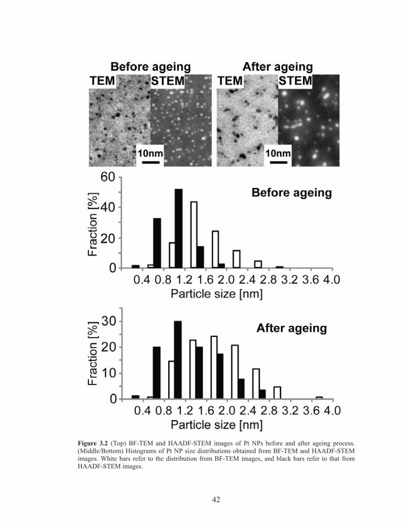
42
Figure 3.2 (Top) BF-TEM and HAADF-STEM images of Pt NPs before and after ageing process.(Middle/Bottom) Histograms of Pt NP size distributions obtained from BF-TEM and HAADF-STEMimages. White bars refer to the distribution from BF-TEM images, and black bars refer to that fromHAADF-STEM images.
43
/ligandnm 0.173 mol
ligands10022.6g/mol 7.331
g10749.1555.01
g10749.1
/41.0nm4ligands of#
223
1818
2 �
�����
�����
�
��
�����
����
���
�
��
S . [3]
Here 331.7 g/mol is the molar mass of the ligand in Figure 3.1A.35 The aged NPs
yielded 0.196 nm2 per thiol following the same calculation. For comparison, the area
per thiol head group for a methanethiol-coated Pt{111} surface is 0.200 nm.46 Many
factors affect the area per thiol head group on metal surfaces, including surface
curvature, existence of metal nanocrystal defects such as edges, steps and vertices, and
tail size of the ligand.39,47-51 The fact that the NP ligand density is similar to that of a
simple alkanethiol on a flat Pt surface suggests that the effects from the high NP
surface curvature cancels the steric effect from the large tail volume, allowing a large
conical angle for the ligand molecule rotation.
2. Hybrid morphology exploration.
We investigated PI-b-PDMAEMA/Pt NP self-assembly with two different PI-
b-PDMAEMA block copolymers, referred to as MK31 (31,000 g/mol, 33 wt. %
PDMAEMA) and MK29 (29,000 g/mol, 17 wt. % PDMAEMA). The polydispersity
index (PDI) of both polymers was below 1.1 (Mw/Mn = 1.03 and 1.06, for MK31 and
MK29, respectively, where Mw is weight average molecular weight and Mn is number
average molecular weight).
We prepared a series of hybrid samples by varying Pt NPs/PI-b-PDMAEMA
ratios. All the Pt NPs used to synthesize hybrids were aged, with ligand head group
densities of ~0.196 nm2 per thiol, following the calculation discussed above. Table 3.1
lists the Pt NPs/PI-b-PDMAEMA ratios of different hybrids and the corresponding
morphologies obtained, as suggested by a combination of small angle x-ray scattering
and TEM analysis, see below. The table also includes the results of our previous
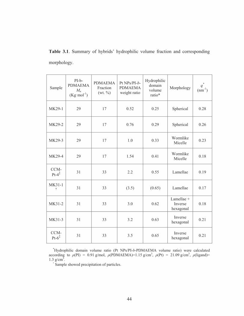
44
Table 3.1. Summary of hybrids’ hydrophilic volume fraction and corresponding
morphology.
Sample
PI-b-PDMAEMA
Mn (Kg·mol-1)
PDMAEMA Fraction (wt. %)
Pt NPs/PI-b-PDMAEMA weight ratio
Hydrophilic domain volume ratio*
Morphology q* (nm-1)
MK29-1 29 17 0.52 0.25 Spherical 0.28
MK29-2 29 17 0.76 0.29 Spherical 0.26
MK29-3 29 17 1.0 0.33 Wormlike Micelle 0.23
MK29-4 29 17 1.54 0.41 Wormlike Micelle 0.18
CCM-Pt-4‡ 31 33 2.2 0.55 Lamellae 0.19
MK31-1 31 33 (3.5) (0.65) Lamellae 0.17
MK31-2 31 33 3.0 0.62 Lamellae +
Inverse hexagonal
0.18
MK31-3 31 33 3.2 0.63 Inverse hexagonal 0.21
CCM-Pt-6‡ 31 33 3.5 0.65 Inverse
hexagonal 0.21
*Hydrophilic domain volume ratio (Pt NPs/PI-b-PDMAEMA volume ratio) were calculated according to �(PI) = 0.91 g/mol, �(PDMAEMA)=1.15 g/cm3, �(Pt) = 21.09 g/cm3, �(ligand)= 1.3 g/cm3.
Sample showed precipitation of particles.
45
report.35 As the volume fraction of the inorganic content increases, four different
morphologies were obtained as revealed by BF-TEM, see Figure 3.3: spherical
micelles (Figure 3.3A), wormlike micelles (Figure 3.3B), lamellae (Figure 3.3C), and
inverse hexagonal cylinders (Figure 3.3D). In the BF-TEM images, PI appears as
bright domains while PDMAEMA/Pt NPs appear dark, with contrast arising from the
electron density difference between the different domains. We note that when more
NPs were added to MK29 with the shorter PDMAEMA chains (5,000 g/mol for MK29
versus 10,000 g/mol for MK31), macrophase separation with aggregated NPs was
observed. Also, in some of the films that used MK29, occasionally NP agglomeration
was observed along with microphase separated structures. All these observations
suggest that MK29’s PDMAEMA chains may be at the lower limit relative to the NP
size necessary to observe good structure control. The radius of gyration calculated for
MK31 and MK29 are 2.5 nm and 1.8 nm, respectively.52 Indeed, the radius of gyration
of MK29 is very close to the average Pt NP size, inconsistent with criteria #3 in our
list above.
Figure 3.4 shows the small-angle X-ray scattering (SAXS) patterns of annealed
hybrids with the four different morphologies. Although the patterns display too few
orders to unambiguously determine phases, if one assumes phases indicated by TEM
(Figure 3.3), the position of the first order is a consistency check of the structure. Here
the scattering vector q is defined as q = 4�sin�/�, where 2� is the scattering angle and �
is the wavelength of the CuK� x-ray beam, 1.54Å. q* signifies the position of the first
peak in the scattering pattern. The first Bragg reflection for the lamellar hybrid MK31-
1 at 0.17 nm-1 corresponds to an interplanar spacing of 36 nm, while that for the
inverse hexagonal hybrid MK31-3 at 0.21 nm-1 corresponds to an channel-to-channel
spacing ((10) period in the hexagonal lattice, *
10 3/4 qd � ) of 35 nm. Both spacings
are consistent with the periods of the nanostructures measured from BF-TEM images.
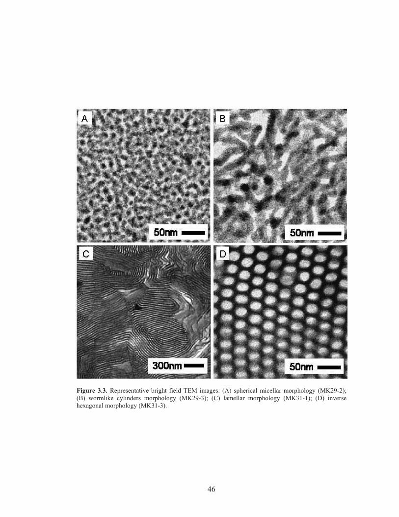
46
Figure 3.3. Representative bright field TEM images: (A) spherical micellar morphology (MK29-2); (B) wormlike cylinders morphology (MK29-3); (C) lamellar morphology (MK31-1); (D) inverse hexagonal morphology (MK31-3).
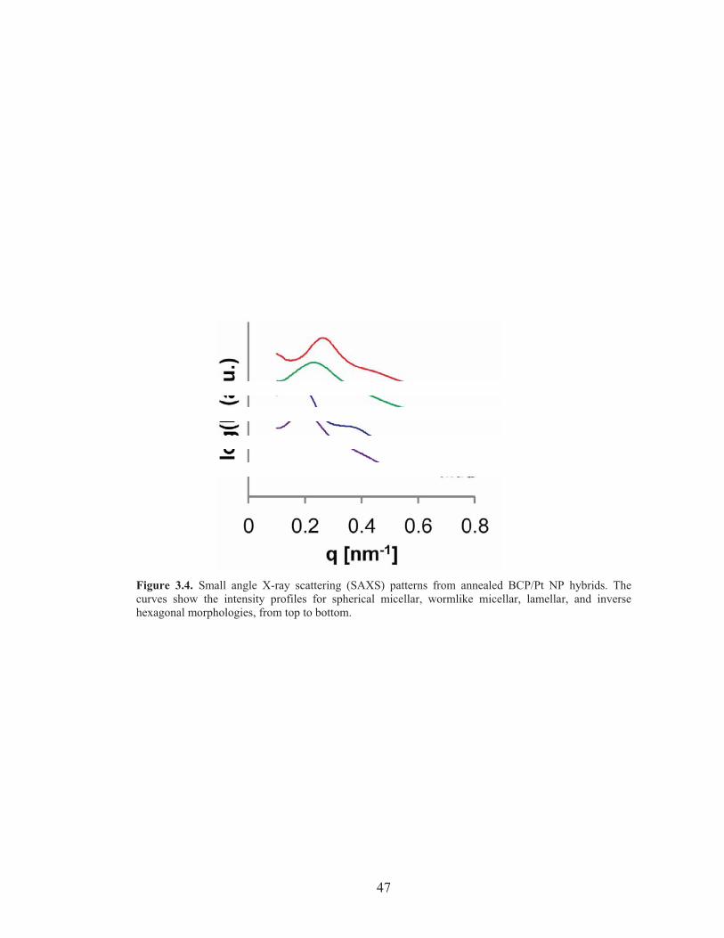
47
Figure 3.4. Small angle X-ray scattering (SAXS) patterns from annealed BCP/Pt NP hybrids. Thecurves show the intensity profiles for spherical micellar, wormlike micellar, lamellar, and inversehexagonal morphologies, from top to bottom.
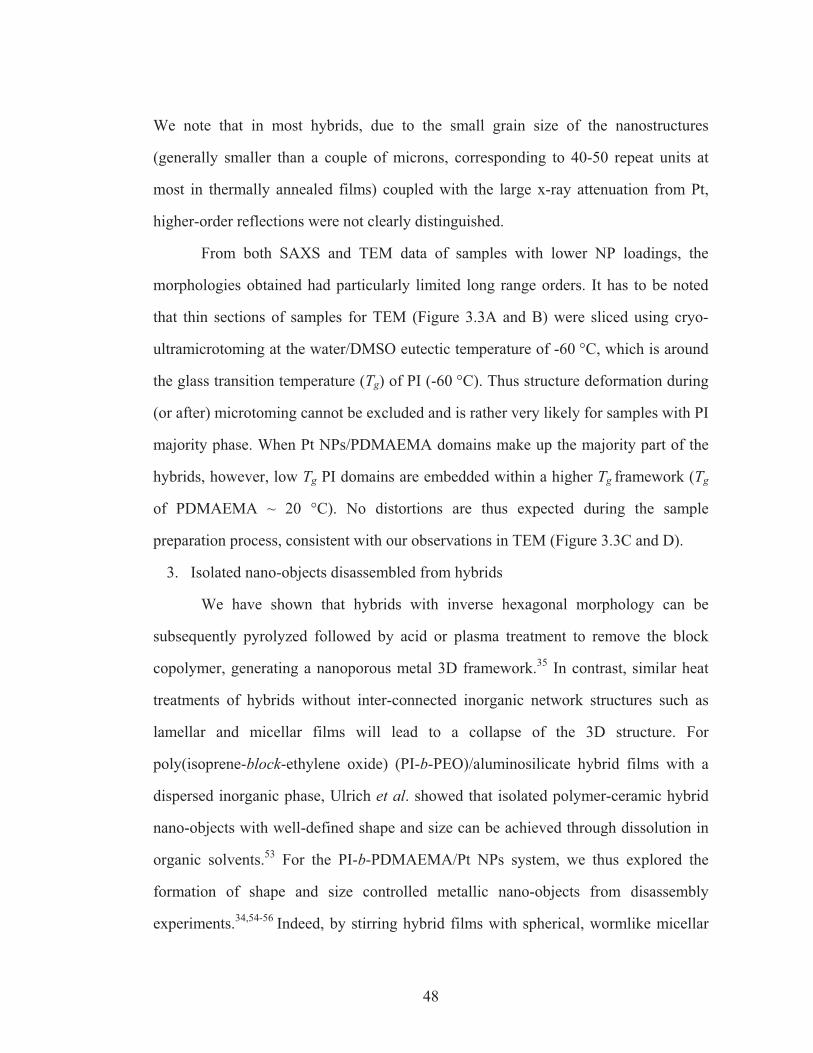
48
We note that in most hybrids, due to the small grain size of the nanostructures
(generally smaller than a couple of microns, corresponding to 40-50 repeat units at
most in thermally annealed films) coupled with the large x-ray attenuation from Pt,
higher-order reflections were not clearly distinguished.
From both SAXS and TEM data of samples with lower NP loadings, the
morphologies obtained had particularly limited long range orders. It has to be noted
that thin sections of samples for TEM (Figure 3.3A and B) were sliced using cryo-
ultramicrotoming at the water/DMSO eutectic temperature of -60 °C, which is around
the glass transition temperature (Tg) of PI (-60 °C). Thus structure deformation during
(or after) microtoming cannot be excluded and is rather very likely for samples with PI
majority phase. When Pt NPs/PDMAEMA domains make up the majority part of the
hybrids, however, low Tg PI domains are embedded within a higher Tg framework (Tg
of PDMAEMA ~ 20 °C). No distortions are thus expected during the sample
preparation process, consistent with our observations in TEM (Figure 3.3C and D).
3. Isolated nano-objects disassembled from hybrids
We have shown that hybrids with inverse hexagonal morphology can be
subsequently pyrolyzed followed by acid or plasma treatment to remove the block
copolymer, generating a nanoporous metal 3D framework.35 In contrast, similar heat
treatments of hybrids without inter-connected inorganic network structures such as
lamellar and micellar films will lead to a collapse of the 3D structure. For
poly(isoprene-block-ethylene oxide) (PI-b-PEO)/aluminosilicate hybrid films with a
dispersed inorganic phase, Ulrich et al. showed that isolated polymer-ceramic hybrid
nano-objects with well-defined shape and size can be achieved through dissolution in
organic solvents.53 For the PI-b-PDMAEMA/Pt NPs system, we thus explored the
formation of shape and size controlled metallic nano-objects from disassembly
experiments.34,54-56 Indeed, by stirring hybrid films with spherical, wormlike micellar
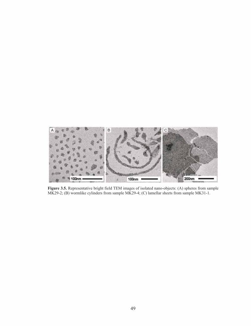
49
Figure 3.5. Representative bright field TEM images of isolated nano-objects: (A) spheres from sampleMK29-2; (B) wormlike cylinders from sample MK29-4; (C) lamellar sheets from sample MK31-1.
50
and lamellar morphologies in cyclohexane or tetrahydrofuran for 4 hours, isolated
spheres, cylinders and nano-sheets were obtained, respectively, as shown in Figure 3.5.
Figure 3.5A shows nano-spheres obtained from micellar structures. Dissolution of
wormlike micelles leads to isolated cylinders with different aspect ratios, see Figure
3.5B. Nano-sheets were obtained from dissolution of lamellar hybrids, see Figure 3.5C.
It should be noted that these results provide independent proof of the structure
assignments that were based on SAXS and TEM results in the previous section. In
analogy to what was observed for the PI-b-PEO/aluminosilicate system, the current
nano-objects have a core-shell structure with a PDMAEMA/Pt NP core and PI chains
as a shell, increasing the solubility of the nano-object in organic solvents.53 Since PI
chains provide only low contrast, the TEM images only show the core of the nano-
objects. High resolution images of these isolated nano-structures further confirm that
the cores consist of small Pt NPs (data not shown as is already evident from Figure
3.5).
The average size of the spheres obtained by dissolution of samples MK29-1
and MK29-2 increased from 14 nm to 17 nm, respectively, consistent with increasing
Pt NP/BC ratios of the hybrids. Likewise, the average dimensions of the nano-
cylinders disassembled from hybrids MK29-3 and MK29-4 increased from 12 nm to
16 nm. The length of the cylinders as well as the size of the nano-sheets obtained from
lamellar hybrids was not very well defined, ranging from several hundred nanometers
to several microns. As demonstrated before for aluminosilicate cylinders, the length
(size) of the nano-objects can be tailored, for example, through ultrasonication,
making this a powerful tool for the formation of well-defined nano-objects.6,57 These
nano-objects are stable in solution for at least one week both in cyclohexane and in
THF (data not shown), indicating that the NPs and PDMAEMA formed an integrated
composite.
51
Conclusion
We have successfully formed BCP/metal hybrid materials from functional
ligand-stabilized Pt NPs and amphiphilic PI-b-PDMAEMA diblock copolymers, with
increasing metal loadings leading to four distinct nanocomposites. The ligand
functionality containing an ionic part and a hydrophilic tail with steric hindrance
ensures high NP solubility in polar solvents as well as compatibility with the
hydrophilic block of the BCP. The Pt NP size distribution was measured by HAADF-
STEM, which enabled a more accurate estimate of the ligand head group density of
the Pt NPs. Disassembly of hybrids without a continuous inorganic phase resulted in
metallic nano-objects with core-shell architecture and well defined shapes. By future
tuning of metal NP/BCP hybrid systems through block copolymer structure/chemistry
variations and/or nanoparticle compositions, other morphologies such as bi- or triply-
continuous structures particularly interesting for energy related applications3,58 as well
as mixed metals based ordered nanostructures should become accessible which may
exhibit novel optical, magnetic or catalytic properties.
Acknowledgment
This publication was supported by a subcontract with Cornell University,
Department of Materials Science and Engineering, under Prime Agreement Award
Number 06-G-031 from the Department of Homeland Security, by Grant Number
R21DE018335 from the National Institute of Dental and Craniofacial Research, by the
U.S. Department of Energy (grant DE-FG02-03ER46072) and by NSF DMR-0605856
and DMR-0404195. Research made use of facilities of the Cornell Center for
Materials Research (CCMR) with funding from the Materials Research Science and
Engineering Center program of NSF (cooperative agreement DMR-0520404). We
thank Prof. Francesco Stellacci in the Department of Materials Science and
52
Engineering, Massachusetts Institute of Technology, and Osman Bakr in the
Department of Applied Physics, Harvard University, for pointing out the ligand
density issue with the Pt NPs, and fruitful discussions about the formation of metal
nanoclusters. The content of this publication is solely the responsibility of the authors
and does not necessarily represent the official view of any of the funding agencies.
53
REFERENCES
1. Bates, F. S. Science 1991, 251, 898. 2. Bates, F. S.; Fredrickson, G. H. Annu. Rev. Phys. Chem. 1990, 41, 525. 3. Cho, B.-K.; Jain, A.; Gruner, S. M.; Wiesner, U. Science 2004, 305, 1598. 4. Kamperman, M.; Wiesner, U. Block Copolymers in Nanoscience, Lazzari, M.; Liu, G.; Lecommandoux, S., Eds. WILEY-VCH Verlag GmbH & KgaA: Weinheim, 2006; p 309. 5. Templin, M.; Franck, A.; DuChesne, A.; Leist, H.; Zhang, Y. M.; Ulrich, R.; Schadler, V.; Wiesner, U. Science 1997, 278, 1795. 6. B. Hamdoun, D. Ausserré, S. Joly, Y. Gallot, V. Cabuil, C. Clinard. J. Phys. II France 1996, 6, 493. 7. Simon, P. F. W.; Ulrich, R.; Spiess, H. W.; Wiesner, U. Chem. Mater. 2001, 13, 3464. 8. Bagshaw, S. A.; Prouzet, E.; Pinnavaia, T. J. Science 1995, 269, 1242. 9. Tanev, P. T.; Pinnavaia, T. J. Science 1995, 267, 865. 10. Zhao, D. Y.; Feng, J. L.; Huo, Q. S.; Melosh, N.; Fredrickson, G. H.; Chmelka, B. F.; Stucky, G. D. Science 1998, 279, 548. 11. Yang, P. D.; Zhao, D. Y.; Margolese, D. I.; Chmelka, B. F.; Stucky, G. D. Nature 1998, 396, 152. 12. Lee, J.; Orilall, M. C.; Warren, S. C.; Kamperman, M.; Disalvo, F. J.; Wiesner, U. Nat. Mater. 2008, 7, 222. 13. Kamperman, M.; Garcia, C. B. W.; Du, P.; Ow, H. S.; Wiesner, U., J. Am. Chem. Soc. 2004, 126, 14708-14709. 14. Malenfant, P. R. L.; Wan, J.; Taylor, S. T.; Manoharan, M. Nat. Nanotechnol. 2007, 463, 78. 15. Chan, Y. N. C.; Craig, G. S. W.; Schrock, R. R.; Cohen, R. E. Chem. Mater. 1992, 4, 885. 16. Chan, Y. N. C.; Schrock, R. R.; Cohen, R. E. Chem. Mater. 1992, 4, 24. 17. Sankaran, V.; Cummins, C. C.; Schrock, R. R.; Cohen, R. E.; Silbey, R. J. J. Am. Chem. Soc. 1990, 112, 6858-6859. 18. Spatz, J. P.; Herzog, T.; Mossmer, S.; Ziemann, P.; Moller, M. Adv. Mater. 1999, 11, 149. 19. Yamauchi, Y.; Sugiyama, A.; Morimoto, R.; Takai, A.; Kuroda, K. Angew. Chem., Int. Ed. 2008, 47, 5371. 20. Bockstaller, M. R.; Lapetnikov, Y.; Margel, S.; Thomas, E. L. J. Am. Chem. Soc. 2003, 125, 5276. 21. Kim, B. J.; Chiu, J. J.; Yi, G. R.; Pine, D. J.; Kramer, E. J. Adv. Mater. 2005, 17, 2618. 22. Kim, B. J.; Bang, J.; Hawker, C. J.; Kramer, E. J. Macromolecules 2006, 39, 4108. 23. Kim, B. J.; Fredrickson, G. H.; Kramer, E. J. Macromolecules 2008, 41, 436-447.
54
24. Chiu, J. J.; Kim, B. J.; Kramer, E. J.; Pine, D. J. J. Am. Chem. Soc. 2005, 127, 5036. 25. Lin, Y.; Boker, A.; He, J. B.; Sill, K.; Xiang, H. Q.; Abetz, C.; Li, X. F.; Wang, J.; Emrick, T.; Long, S.; Wang, Q.; Balazs, A.; Russell, T. P. Nature 2005, 434, 55. 26. Oren, R.; Liang, Z.; Barnard, J. S.; Warren, S. C.; Wiesner, U.; Huck, W. T. S. J. Am. Chem. Soc. 2009, 131, 1670. 27. Jain, A.; Wiesner, U. Macromolecules 2004, 37, 5665. 28. Attard, G. S.; Göltner, C. G.; Corker, J. M.; Henke, S.; Templer, R. H. Angew. Chem., Int. Ed. 1997, 36, 1315. 29. Yamauchi, Y.; Yokoshima, T.; Mukaibo, H.; Tezuka, M.; Shigeno, T.; Momma, T.; Osaka, T.; Kuroda, K. Chem. Lett. 2004, 33, 542. 30. Lo, C. T.; Lee, B.; Pol, V. G.; Rago, N. L. D.; Seifert, S.; Winans, R. E.; Thiyagarajan, P. Macromolecules 2007, 40, 8302. 31. Park, J. H.; Sun, Y. J.; Goldman, Y. E.; Composto, R. J. Macromolecules 2009, 42, 1017. 32. Huh, J.; Ginzburg, V. V.; Balazs, A. C. Macromolecules 2000, 33, 8085. 33. Thompson, R. B.; Ginzburg, V. V.; Matsen, M. W.; Balazs, A. C. Science 2001, 292, 2469. 34. Warren, S. C.; DiSalvo, F. J.; Wiesner, U. Nat. Mater. 2007, 7, 156. 35. Warren, S. C.; Messina, L. C.; Slaughter, L. S.; Kamperman, M.; Zhou, Q.; Gruner, S. M.; DiSalvo, F. J.; Wiesner, U. Science 2008, 320, 1748. 36. Warren, S. C.; Wiesner, U. Pure Appl. Chem.2009, 81, 73. 37. Warren, S. C.; Banholzer, M. J.; Slaughter, L. S.; Giannelis, E. P.; DiSalvo, F. J.; Wiesner, U. J. Am. Chem. Soc. 2006, 128, 12074. 38. Creutz, S.; Teyssie, P.; Jerome, R. Macromolecules 1997, 30, 5596. 39. Eklund, S. E.; Cliffel, D. E. Langmuir 2004, 20, 6012. 40. Otten, M. T., Journal of Electron Microscopy Technique 1991, 17 (2), 221-230. 41. The terms nanoparticle, and nanocluster are loosely defined. According to literature42, the term nanoparticle refers either “to all 0 D nanosized building blocks” or “amorphous or semicrystalline 0D nanostructures with dimensions larger than 10 nm.” Nanoclusters, on the other hand, refer to smaller-sized nanostructures. In this article we use the term nanoparticles for our platinum nanomaterials to maintain consistency with our previous publications. 35,36 42. Fahlman, B. D. Materials Chemistry. Springer: Dordrecht, The Netherlands, 2007. 43. Dance, I. G.; Fisher, K. J.; Banda, R. M. H.; Scudder, M. L. Inorg. Chem. 1991, 30, 183. 44. Jadzinsky, P. D.; Calero, G.; Ackerson, C. J.; Bushnell, D. A.; Kornberg, R. D. Science 2007, 318, 430. 45. Zamborini, F. P.; Gross, S. M.; Murray, R. W. Langmuir 2001, 17, 481. 46. Kim, S. S.; Kim, Y.; Kim, H. I.; Lee, S. H.; Lee, T. R.; Perry, S. S.; Rabalais, J. W. J. Chem. Phys. 1998, 109, 9574. 47. Love, J. C.; Estroff, L. A.; Kriebel, J. K.; Nuzzo, R. G.; Whitesides, G. M. Chem. Rev. 2005, 105, 1103. 48. Hostetler, M. J.; Stokes, J. J.; Murray, R. W. Langmuir 1996, 12, 3604.
55
49. Hostetler, M. J.; Wingate, J. E.; Zhong, C.-J.; Harris, J. E.; Vachet, R. W.; Clark, M. R.; Londono, J. D.; Green, S. J.; Stokes, J. J.; Wignall, G. D.; Glish, G. L.; Porter, M. D.; Evans, N. D.; Murray, R. W., Langmuir 1998, 14, 17. 50. Luedtke, W. D.; Landman, U., J. Phys. Chem. B 1998, 102, 6566. 51. Hill, H. D.; Millstone, J. E.; Banholzer, M. J.; Mirkin, C. A. ACS Nano 2009, 3, 418. 52. Santore, M. M.; Kozlova U.S. Patent Application, 11/592,454, 2006. 53. Ulrich, R.; DuChesne, A.; Templin, M.; Wiesner, U. Adv. Mater. 1999, 11, 141. 54. Li, F.; Wang, Z.; Stein, A. Angew. Chem., Int. Ed. 2007, 46, 1885. 55. Li, F.; Delo, S. A.; Stein, A. Angew. Chem., Int. Ed. 2007, 46, 6666. 56. Lin, X.; Wang, Y.; Wu, L. Langmuir, 2009, 25, 6081. 57. Wang, X.; Guerin, G.; Wang, H.; Wang, Y.; Manners, I.; Winnik, M. A. Science 2007, 317, 644. 58. Crossland, E. J. W.; Kamperman, M.; Nedelcu, M.; Ducati, C.; Wiesner, U.; Smilgies, D. F.; Toombes, G. E. S.; Hillmyer, M. A.; Ludwigs, S.; Steiner, U.; Snaith, H. J. Nano Lett. 2009, 9, 2807.
56
CHAPTER 4
HIERARCHICAL POROUS POLYMER SCAFFOLDS MADE SIM2PLE:
COMBINING SPINODAL DECOMPOSITION WITH BLOCK COPOLYMER
ASSEMBLY PLUS RINSING*
Abstract
Hierarchical porous polymer materials are of increasing importance due to
their potential application in catalysis, separation technology or bioengineering. While
specific examples for their synthesis exist there is a need for a facile yet versatile
conceptual approach to hierarchical porous polymer scaffolds with tunable ordered
mesostructure. Here we introduce a method termed Spinodal-decomposition Induced
Macro and Meso-phase separation PLus Extraction by rinsing (SIM2PLE). It combines
well-established concepts of spinodal decomposition at the macroscale and block
copolymer self-assembly to tune morphology at the nanoscale with porosity formation
on both length scales via rinsing with protic solvents such as water and alcohols. As a
first example here hierarchical porous films are formed from poly(styrene-block-
ethylene oxide) (PS-b-PEO) and a PEO oligomer as a small additive. Varying casting
temperatures and solvents enables access to tailored hexagonal and cubic
mesostructures. We expect this method based on simple thermodynamic principles to
provide a powerful approach for the synthesis of hierarchically porous materials.
*Sai, H.; Tan, K.W.; Hur, K.; Gruner, S. M.; Wiesner, U. In preparation.
57
Hierarchically porous materials, ubiquitous in biological systems1-3 and a
target for synthetic materials,4-8 provide synergies between mechanical properties,
transport properties and enhanced surface area. Integrating mesoscale (2-50 nm)
porosity with three-dimensional continuous macropores (> 50 nm) is of particular
importance as it combines high specific surface area with high flux and pore
accessibility desired e.g. in catalytic conversions. Potential applications of such
hierarchically structured materials range from catalysis to separation technology to
bioengineering. Amongst polymeric materials, block copolymer (BCP) self-assembly
is known to offer access to mesoscale ordered structures with tunable size and
morphology through control over molecular parameters such as block chemistry,
sequence and molar mass.9, 10 Specific methods have been developed to form
mesopores from BCP-based assemblies, including chemical block removal11-13 and
swelling with sacrificial components.14-16 The strong interest in hierarchical polymer
scaffolds has resulted in specific strategies for structure generation at multiple length
scales using BCPs, such as confined self-assembly in preformed macroscale
templates17-23 and non-solvent- or polymerization- induced phase separation.24-27 As
pointed out in detail recently, however, when combined together, these approaches
often require specific and invasive chemistries, only work in narrow synthesis
parameter windows, or rely on multiple tedious steps that limit their general use.16
There is thus a need for a facile yet versatile conceptual approach to hierarchically
porous polymer scaffolds with well-controlled structures.
A well-studied physical phenomenon in polymer science is the spinodal
decomposition of polymer blends.16, 28-32 By driving a multicomponent polymeric
mixture to a supersaturated state through control of temperature or through quick
solvent evaporation, a continuous interface at the micron-scale emerges upon phase
segregation. A facile and versatile, yet unexplored approach for generating
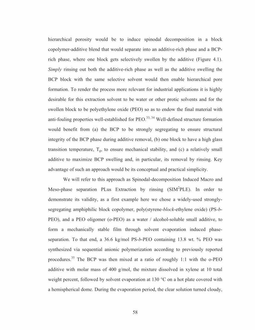
58
hierarchical porosity would be to induce spinodal decomposition in a block
copolymer-additive blend that would separate into an additive-rich phase and a BCP-
rich phase, where one block gets selectively swollen by the additive (Figure 4.1).
Simply rinsing out both the additive-rich phase as well as the additive swelling the
BCP block with the same selective solvent would then enable hierarchical pore
formation. To render the process more relevant for industrial applications it is highly
desirable for this extraction solvent to be water or other protic solvents and for the
swollen block to be polyethylene oxide (PEO) so as to endow the final material with
anti-fouling properties well-established for PEO.33, 34 Well-defined structure formation
would benefit from (a) the BCP to be strongly segregating to ensure structural
integrity of the BCP phase during additive removal, (b) one block to have a high glass
transition temperature, Tg, to ensure mechanical stability, and (c) a relatively small
additive to maximize BCP swelling and, in particular, its removal by rinsing. Key
advantage of such an approach would be its conceptual and practical simplicity.
We will refer to this approach as Spinodal-decomposition Induced Macro and
Meso-phase separation PLus Extraction by rinsing (SIM2PLE). In order to
demonstrate its validity, as a first example here we chose a widely-used strongly-
segregating amphiphilic block copolymer, poly(styrene-block-ethylene oxide) (PS-b-
PEO), and a PEO oligomer (o-PEO) as a water / alcohol-soluble small additive, to
form a mechanically stable film through solvent evaporation induced phase-
separation. To that end, a 36.6 kg/mol PS-b-PEO containing 13.8 wt. % PEO was
synthesized via sequential anionic polymerization according to previously reported
procedures.35 The BCP was then mixed at a ratio of roughly 1:1 with the o-PEO
additive with molar mass of 400 g/mol, the mixture dissolved in xylene at 10 total
weight percent, followed by solvent evaporation at 130 °C on a hot plate covered with
a hemispherical dome. During the evaporation period, the clear solution turned cloudy,
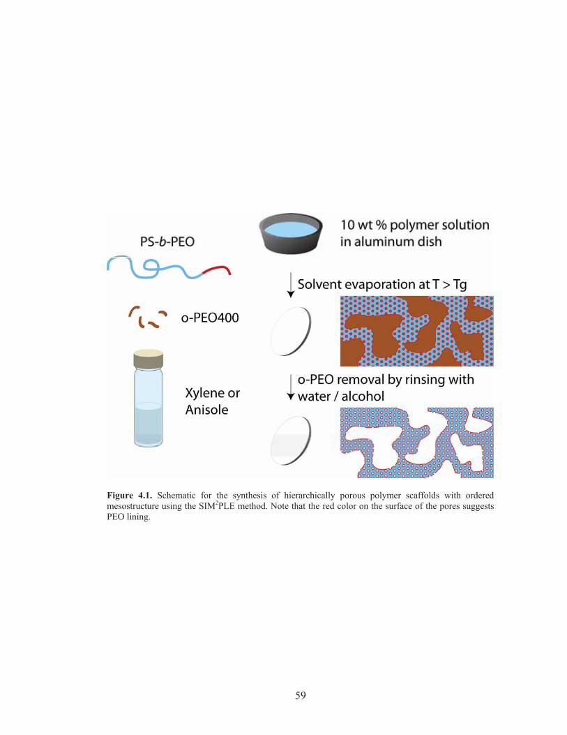
59
Figure 4.1. Schematic for the synthesis of hierarchically porous polymer scaffolds with orderedmesostructure using the SIM2PLE method. Note that the red color on the surface of the pores suggestsPEO lining.
60
indicating macrophase separation induced scattering of visible light. After xylene
evaporation was complete, as indicated by mass loss, the resulting white film was
immersed in the protic solvents water, methanol or ethanol to remove o-PEO. Drying
the film yielded a lightweight material with a highly opaque appearance.
Figure 4.2 shows scanning-electron microscopy (SEM) images of the film
cross-section after removal of o-PEO via rinsing in methanol. Randomly distributed
porosity is observed on the micrometer length scale throughout the film (see Figure
4.2a,b). These macropores, albeit broadly distributed in size, form an interconnected
network characteristic of co-continuous structures obtained via spinodal
decomposition.25 Within the polymer struts, hexagonally arranged cylindrical
mesopores are observed that have a radius of ~13 nm, as estimated from an analysis of
the SEM images (see Figure 4.2c,d). These mesopores are preferentially aligned
parallel to the macropore walls, and a fraction of pores are observed to be accessible
from the macropores (see Figure 4.2c). Rinsing with other protic solvents (water and
ethanol) resulted in the same structures (see Supplementary Materials, Figure 4.S1).
Removal of o-PEO from the bulk film is confirmed by comparing gel-
permeation chromatography (GPC) results with N,N-dimethylformamide (DMF) as an
eluent for the as-cast film and films rinsed with the three protic solvents water,
methanol and ethanol (see Figure 4.2e). From the refractive index detector response,
90-95% of the o-PEO is removed by rinsing the as-cast film with these protic solvents
for 2 hours at room temperature (compare peaks on the right at ~35 mL). Successful
removal of the oligomeric additive corroborates the high degree of interconnected
macro- and mesoporosity throughout the structure as observed in SEM.
Further evidence for easy accessibility of, and removal of short-chain o-PEO
from, mesopores via rinsing could be established via small angle x-ray scattering
(SAXS). Removal of o-PEO should lead to higher electron density contrast and thus
61
Figure 4.2. (a-d) SEM images at different length scales of a fractured cross-section of a bulkhierarchically porous block copolymer film after removal of o-PEO in methanol. (e) Gel-permeationchromatography traces of as-made and rinsed samples. Each curve is normalized in RI detectorresponse at the peak height of the PS-b-PEO peak, and calibrated for elution volume at the PS-b-PEOpeak. (f) Small-angle X-ray scattering patterns of the as-cast film and films after o-PEO400 removalthrough rinsing in protic solvents. Curves for methanol-rinsed and ethanol-rinsed samples are shiftedvertically by 102 and 104 upwards, respectively. Tick marks correspond to expected peak positions for alattice with P6mm symmetry with primary peak position of q* = 0.154 nm-1.
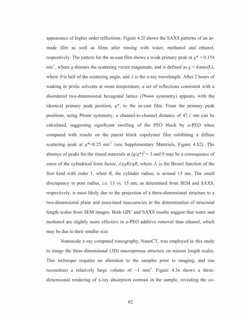
62
appearance of higher order reflections. Figure 4.2f shows the SAXS patterns of an as-
made film as well as films after rinsing with water, methanol and ethanol,
respectively. The pattern for the as-cast film shows a weak primary peak at q* = 0.154
nm-1, where q denotes the scattering vector magnitude, and is defined as q = ��sin�/�,
where � is half of the scattering angle, and � is the x-ray wavelength. After 2 hours of
soaking in protic solvents at room temperature, a set of reflections consistent with a
disordered two-dimensional hexagonal lattice (P6mm symmetry) appears, with the
identical primary peak position, q*, to the as-cast film. From the primary peak
positions, using P6mm symmetry, a channel-to-channel distance of 47.1 nm can be
calculated, suggesting significant swelling of the PEO block by o-PEO when
compared with results on the parent block copolymer film exhibiting a diffuse
scattering peak at q*=0.25 nm-1 (see Supplementary Materials, Figure 4.S2). The
absence of peaks for the rinsed materials at (q/q*)2 = 3 and 9 may be a consequence of
zeros of the cylindrical form factor, J1(qR)/qR, where J1 is the Bessel function of the
first kind with order 1, when R, the cylinder radius, is around 15 nm. The small
discrepancy in pore radius, i.e. 13 vs. 15 nm, as determined from SEM and SAXS,
respectively, is most likely due to the projection of a three-dimensional structure to a
two-dimensional plane and associated inaccuracies in the determination of structural
length scales from SEM images. Both GPC and SAXS results suggest that water and
methanol are slightly more effective in o-PEO additive removal than ethanol, which
may be due to their smaller size.
Nanoscale x-ray computed tomography, NanoCT, was employed in this study
to image the three-dimensional (3D) macroporous structure on micron length scales.
This technique requires no alteration to the samples prior to imaging, and can
reconstruct a relatively large volume of ~1 mm3. Figure 4.3a shows a three-
dimensional rendering of x-ray absorption contrast in the sample, revealing the co-
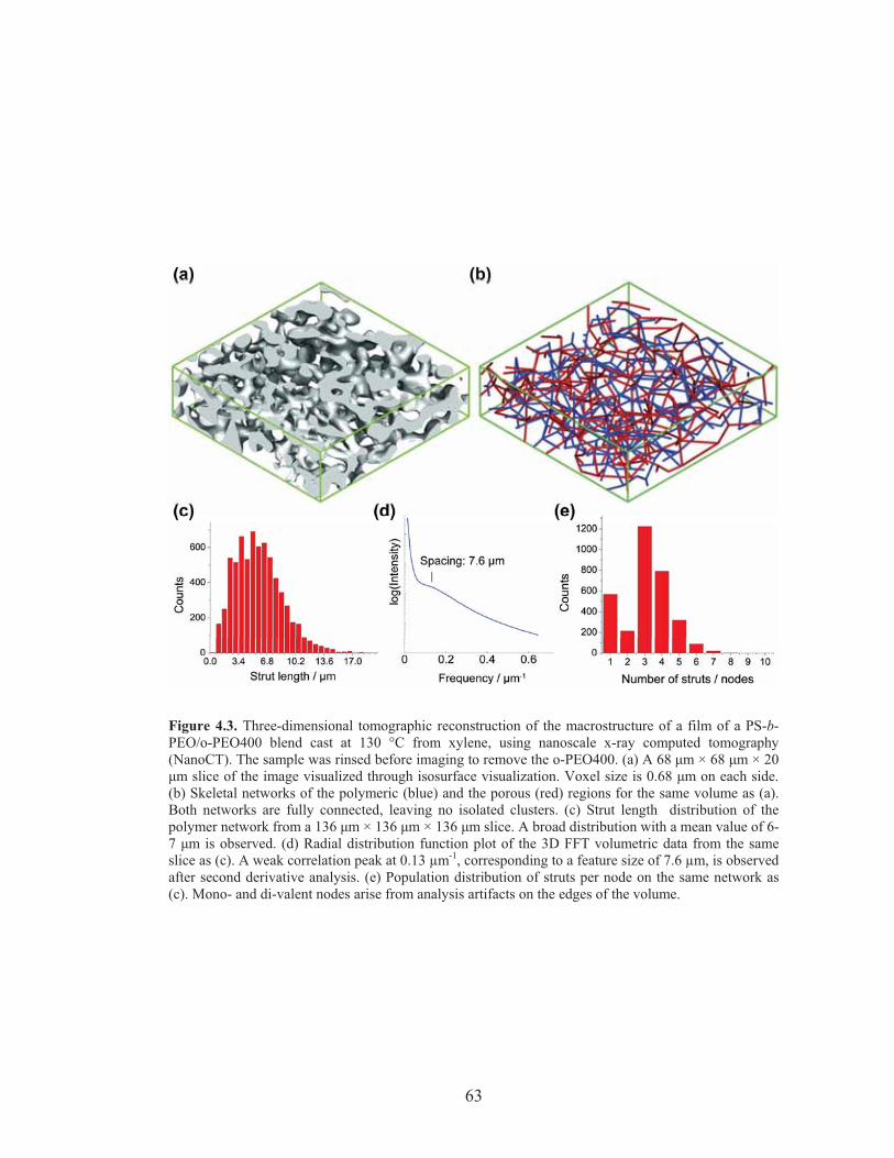
63
Figure 4.3. Three-dimensional tomographic reconstruction of the macrostructure of a film of a PS-b-PEO/o-PEO400 blend cast at 130 °C from xylene, using nanoscale x-ray computed tomography(NanoCT). The sample was rinsed before imaging to remove the o-PEO400. (a) A 68 �m × 68 �m × 20�m slice of the image visualized through isosurface visualization. Voxel size is 0.68 �m on each side.(b) Skeletal networks of the polymeric (blue) and the porous (red) regions for the same volume as (a).Both networks are fully connected, leaving no isolated clusters. (c) Strut length distribution of thepolymer network from a 136 �m × 136 �m × 136 �m slice. A broad distribution with a mean value of 6-7 �m is observed. (d) Radial distribution function plot of the 3D FFT volumetric data from the sameslice as (c). A weak correlation peak at 0.13 μm-1, corresponding to a feature size of 7.6 μm, is observedafter second derivative analysis. (e) Population distribution of struts per node on the same network as(c). Mono- and di-valent nodes arise from analysis artifacts on the edges of the volume.
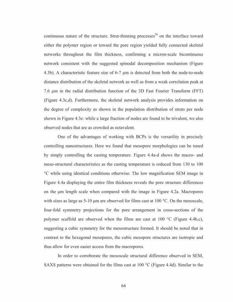
64
continuous nature of the structure. Strut-thinning processes36 on the interface toward
either the polymer region or toward the pore region yielded fully connected skeletal
networks throughout the film thickness, confirming a micron-scale bicontinuous
network consistent with the suggested spinodal decomposition mechanism (Figure
4.3b). A characteristic feature size of 6-7 μm is detected from both the node-to-node
distance distribution of the skeletal network as well as from a weak correlation peak at
7.6 μm in the radial distribution function of the 3D Fast Fourier Transform (FFT)
(Figure 4.3c,d). Furthermore, the skeletal network analysis provides information on
the degree of complexity as shown in the population distribution of struts per node
shown in Figure 4.3e: while a large fraction of nodes are found to be trivalent, we also
observed nodes that are as crowded as octavalent.
One of the advantages of working with BCPs is the versatility in precisely
controlling nanostructures. Here we found that mesopore morphologies can be tuned
by simply controlling the casting temperature. Figure 4.4a-d shows the macro- and
meso-structural characteristics as the casting temperature is reduced from 130 to 100
°C while using identical conditions otherwise. The low magnification SEM image in
Figure 4.4a displaying the entire film thickness reveals the pore structure differences
on the �m length scale when compared with the image in Figure 4.2a. Macropores
with sizes as large as 5-10 �m are observed for films cast at 100 °C. On the mesoscale,
four-fold symmetry projections for the pore arrangement in cross-sections of the
polymer scaffold are observed when the films are cast at 100 °C (Figure 4.4b,c),
suggesting a cubic symmetry for the mesostructure formed. It should be noted that in
contrast to the hexagonal mesopores, the cubic mesopore structures are isotropic and
thus allow for even easier access from the macropores.
In order to corroborate the mesoscale structural difference observed in SEM,
SAXS patterns were obtained for the films cast at 100 °C (Figure 4.4d). Similar to the
65
Figure 4.4. (a-c): SEM images of film cross-sections of PS-b-PEO/o-PEO400 blends cast from xylene at 100 °C at increasing magnifications. Films were rinsed prior to exposing a fresh cross-section for imaging. Images show macroporosity (a), interconnected mesopores accessible from the macropores (b)and four-fold symmetry in the mesoscale porosity (c). (d) SAXS patterns of as-made and rinsed films cast at 100 °C. Spectrum for the rinsed film is shifted in intensity compared to results from as-made films. (e) SEM image of a film cross-section of a PS-b-PEO/o-PEO400 blend cast from anisole at 130 °C. (f) SAXS patterns of as-made and rinsed films cast at 130 °C from anisole.
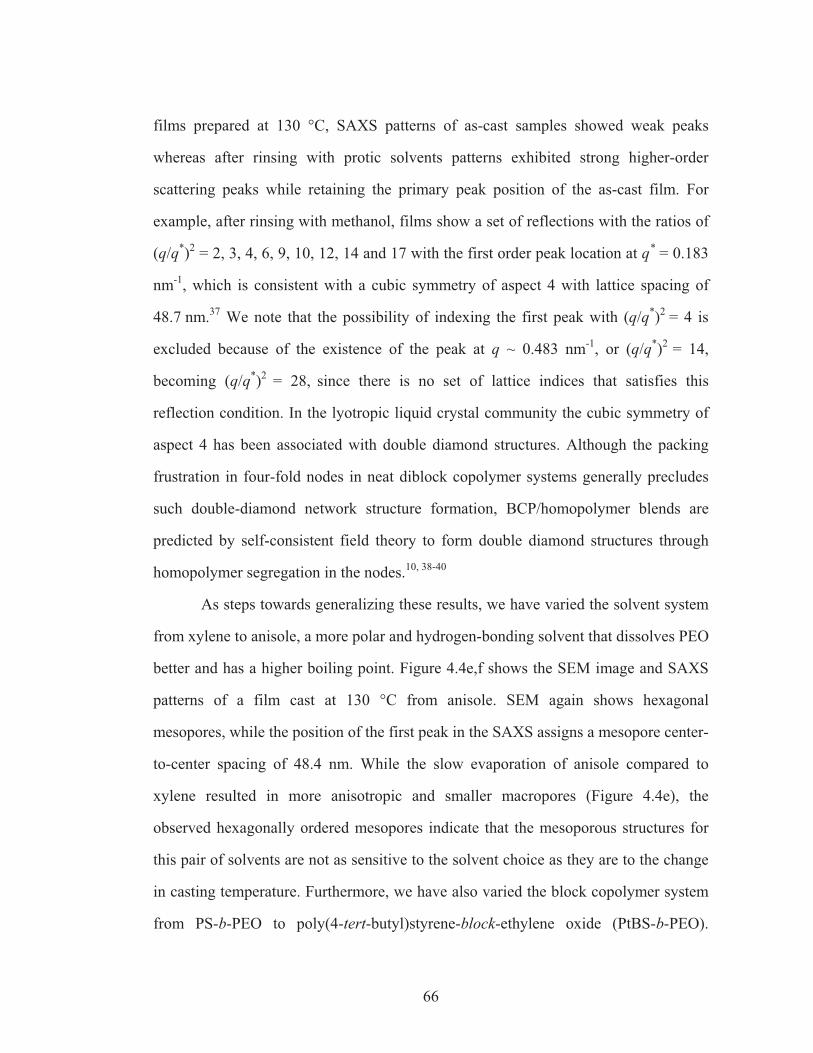
66
films prepared at 130 °C, SAXS patterns of as-cast samples showed weak peaks
whereas after rinsing with protic solvents patterns exhibited strong higher-order
scattering peaks while retaining the primary peak position of the as-cast film. For
example, after rinsing with methanol, films show a set of reflections with the ratios of
(q/q*)2 = 2, 3, 4, 6, 9, 10, 12, 14 and 17 with the first order peak location at q* = 0.183
nm-1, which is consistent with a cubic symmetry of aspect 4 with lattice spacing of
48.7 nm.37 We note that the possibility of indexing the first peak with (q/q*)2 = 4 is
excluded because of the existence of the peak at q ~ 0.483 nm-1, or (q/q*)2 = 14,
becoming (q/q*)2 = 28, since there is no set of lattice indices that satisfies this
reflection condition. In the lyotropic liquid crystal community the cubic symmetry of
aspect 4 has been associated with double diamond structures. Although the packing
frustration in four-fold nodes in neat diblock copolymer systems generally precludes
such double-diamond network structure formation, BCP/homopolymer blends are
predicted by self-consistent field theory to form double diamond structures through
homopolymer segregation in the nodes.10, 38-40
As steps towards generalizing these results, we have varied the solvent system
from xylene to anisole, a more polar and hydrogen-bonding solvent that dissolves PEO
better and has a higher boiling point. Figure 4.4e,f shows the SEM image and SAXS
patterns of a film cast at 130 °C from anisole. SEM again shows hexagonal
mesopores, while the position of the first peak in the SAXS assigns a mesopore center-
to-center spacing of 48.4 nm. While the slow evaporation of anisole compared to
xylene resulted in more anisotropic and smaller macropores (Figure 4.4e), the
observed hexagonally ordered mesopores indicate that the mesoporous structures for
this pair of solvents are not as sensitive to the solvent choice as they are to the change
in casting temperature. Furthermore, we have also varied the block copolymer system
from PS-b-PEO to poly(4-tert-butyl)styrene-block-ethylene oxide (PtBS-b-PEO).
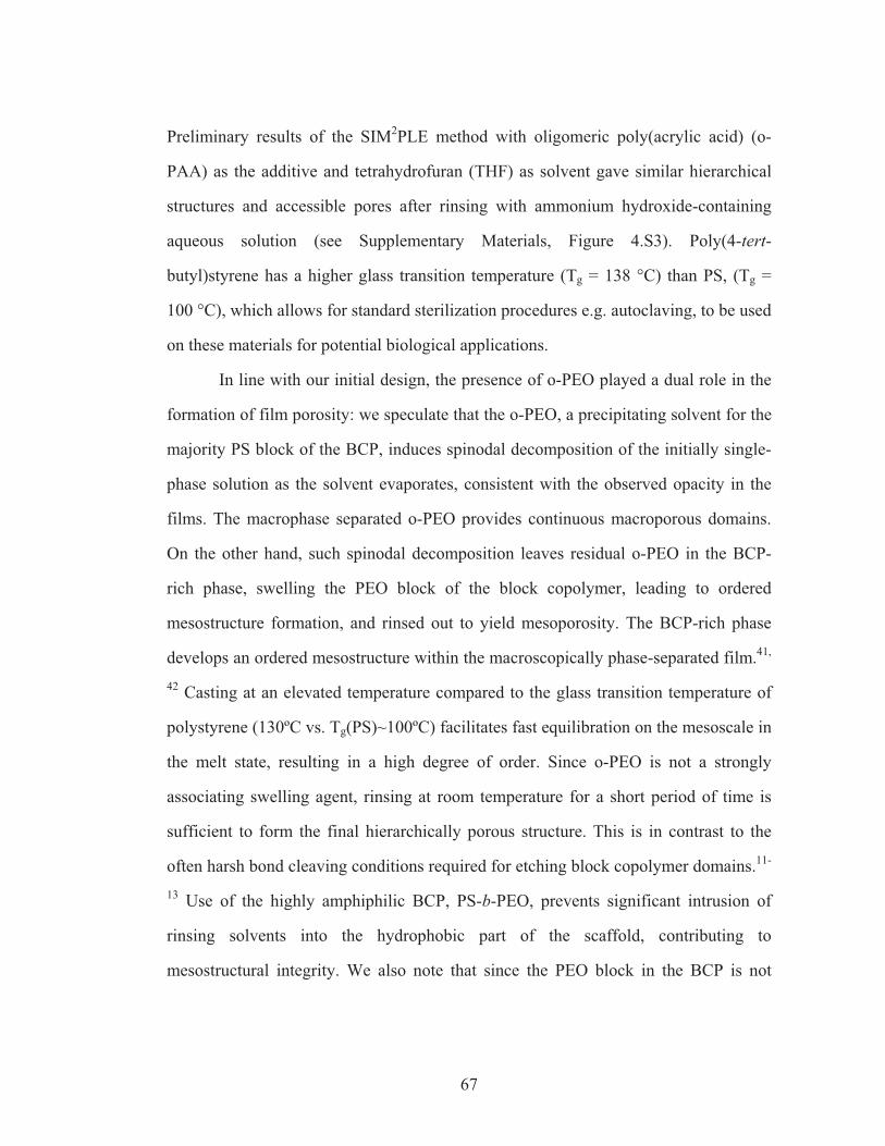
67
Preliminary results of the SIM2PLE method with oligomeric poly(acrylic acid) (o-
PAA) as the additive and tetrahydrofuran (THF) as solvent gave similar hierarchical
structures and accessible pores after rinsing with ammonium hydroxide-containing
aqueous solution (see Supplementary Materials, Figure 4.S3). Poly(4-tert-
butyl)styrene has a higher glass transition temperature (Tg = 138 °C) than PS, (Tg =
100 °C), which allows for standard sterilization procedures e.g. autoclaving, to be used
on these materials for potential biological applications.
In line with our initial design, the presence of o-PEO played a dual role in the
formation of film porosity: we speculate that the o-PEO, a precipitating solvent for the
majority PS block of the BCP, induces spinodal decomposition of the initially single-
phase solution as the solvent evaporates, consistent with the observed opacity in the
films. The macrophase separated o-PEO provides continuous macroporous domains.
On the other hand, such spinodal decomposition leaves residual o-PEO in the BCP-
rich phase, swelling the PEO block of the block copolymer, leading to ordered
mesostructure formation, and rinsed out to yield mesoporosity. The BCP-rich phase
develops an ordered mesostructure within the macroscopically phase-separated film.41,
42 Casting at an elevated temperature compared to the glass transition temperature of
polystyrene (130ºC vs. Tg(PS)~100ºC) facilitates fast equilibration on the mesoscale in
the melt state, resulting in a high degree of order. Since o-PEO is not a strongly
associating swelling agent, rinsing at room temperature for a short period of time is
sufficient to form the final hierarchically porous structure. This is in contrast to the
often harsh bond cleaving conditions required for etching block copolymer domains.11-
13 Use of the highly amphiphilic BCP, PS-b-PEO, prevents significant intrusion of
rinsing solvents into the hydrophobic part of the scaffold, contributing to
mesostructural integrity. We also note that since the PEO block in the BCP is not
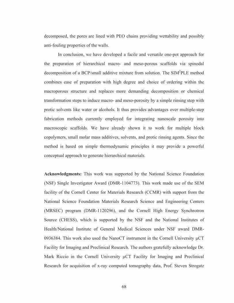
68
decomposed, the pores are lined with PEO chains providing wettability and possibly
anti-fouling properties of the walls.
In conclusion, we have developed a facile and versatile one-pot approach for
the preparation of hierarchical macro- and meso-porous scaffolds via spinodal
decomposition of a BCP/small additive mixture from solution. The SIM2PLE method
combines ease of preparation with high degree and choice of ordering within the
macroporous structure and replaces more demanding decomposition or chemical
transformation steps to induce macro- and meso-porosity by a simple rinsing step with
protic solvents like water or alcohols. It thus provides advantages over multiple-step
fabrication methods currently employed for integrating nanoscale porosity into
macroscopic scaffolds. We have already shown it to work for multiple block
copolymers, small molar mass additives, solvents, and protic rinsing agents. Since the
method is based on simple thermodynamic principles it may provide a powerful
conceptual approach to generate hierarchical materials.
Acknowledgments: This work was supported by the National Science Foundation
(NSF) Single Investigator Award (DMR-1104773). This work made use of the SEM
facility of the Cornell Center for Materials Research (CCMR) with support from the
National Science Foundation Materials Research Science and Engineering Centers
(MRSEC) program (DMR-1120296), and the Cornell High Energy Synchrotron
Source (CHESS), which is supported by the NSF and the National Institutes of
Health/National Institute of General Medical Sciences under NSF award DMR-
0936384. This work also used the NanoCT instrument in the Cornell University μCT
Facility for Imaging and Preclinical Research. The authors gratefully acknowledge Dr.
Mark Riccio in the Cornell University μCT Facility for Imaging and Preclinical
Research for acquisition of x-ray computed tomography data, Prof. Steven Strogatz

69
(Department of Mathematics and School of Mechanical and Aerospace Engineering,
Cornell University) for fruitful discussions, and Rachel Dorin and Ji-yeob Kim
(Department of Materials Science and Engineering, Cornell University) for
experimental assistance and discussion.
70
REFERENCES
1. Weiner, S.; Wagner, H. D., Annu Rev Mater Sci 1998, 28, 271. 2. Autumn, K.; Liang, Y. A.; Hsieh, S. T.; Zesch, W.; Chan, W. P.; Kenny, T. W.; Fearing, R.; Full, R. J., Nature 2000, 405 (6787), 681. 3. Aizenberg, J.; Weaver, J. C.; Thanawala, M. S.; Sundar, V. C.; Morse, D. E.; Fratzl, P., Science 2005, 309 (5732), 275. 4. Lakes, R., Nature 1993, 361 (6412), 511. 5. Yang, P. D.; Deng, T.; Zhao, D. Y.; Feng, P. Y.; Pine, D.; Chmelka, B. F.; Whitesides, G. M.; Stucky, G. D., Science 1998, 282 (5397), 2244. 6. Sanchez, C.; Arribart, H.; Guille, M. M. G., Nat. Mater. 2005, 4 (4), 277. 7. Kamperman, M.; Burns, A.; Weissgraeber, R.; van Vegten, N.; Warren, S. C.; Gruner, S. M.; Baiker, A.; Wiesner, U., Nano Lett. 2009, 9 (7), 2756. 8. Innocenzi, P.; Malfatti, L.; Soler-Illia, G. J. A. A., Chem. Mater. 2011, 23 (10), 2501. 9. Bates, F. S.; Fredrickson, G. H., Annu. Rev. Phys. Chem. 1990, 41 (1), 525. 10. Matsen, M. W.; Bates, F. S., Macromolecules 1996, 29 (23), 7641. 11. Lee, J. S.; Hirao, A.; Nakahama, S., Macromolecules 1988, 21 (1), 274. 12. Urbas, A. M.; Maldovan, M.; DeRege, P.; Thomas, E. L., Adv. Mater. 2002, 14 (24), 1850. 13. Zalusky, A. S.; Olayo-Valles, R.; Wolf, J. H.; Hillmyer, M. A., J. Am. Chem. Soc. 2002, 124 (43), 12761. 14. Maki-Ontto, R.; de Moel, K.; de Odorico, W.; Ruokolainen, J.; Stamm, M.; ten Brinke, G.; Ikkala, O., Adv. Mater. 2001, 13 (2), 117. 15. Wang, Y.; Tong, L.; Steinhart, M., ACS Nano 2011, 5 (3), 1928. 16. Li, L.; Shen, X.; Hong, S. W.; Hayward, R. C.; Russell, T. P., Angew. Chem., Int. Ed. 2012, 51 (17), 4089. 17. Rider, D. A.; Chen, J. I. L.; Eloi, J.-C.; Arsenault, A. C.; Russell, T. P.; Ozin, G. A.; Manners, I., Macromolecules 2008, 41 (6), 2250. 18. Chen, D.; Park, S.; Chen, J.-T.; Redston, E.; Russell, T. P., ACS Nano 2009, 3 (9), 2827. 19. Dobriyal, P.; Xiang, H.; Kazuyuki, M.; Chen, J.-T.; Jinnai, H.; Russell, T. P., Macromolecules 2009, 42 (22), 9082. 20. Escale, P.; Save, M.; Lapp, A.; Rubatat, L.; Billon, L., Soft Matter 2010, 6 (14), 3202. 21. Jones, B. H.; Lodge, T. P., Chem. Mater. 2010, 22 (4), 1279. 22. Jones, B. H.; Lodge, T. P., ACS Nano 2011, 5 (11), 8914. 23. Knoll, W.; Caminade, A. M.; Char, K.; Duran, H.; Feng, C. L.; Gitsas, A.; Kim, D. H.; Lau, A.; Lazzara, T. D.; Majoral, J. P.; Steinhart, M.; Yameen, B.; Zhong, X. H., Small 2011, 7 (10), 1384. 24. Peinemann, K.-V.; Abetz, V.; Simon, P. F. W., Nat. Mater. 2007, 6 (12), 992. 25. Nakanishi, K.; Amatani, T.; Yano, S.; Kodaira, T., Chem. Mater. 2008, 20 (3), 1108.
71
26. Phillip, W. A.; Dorin, R. M.; Werner, J.; Hoek, E. M. V.; Wiesner, U.; Elimelech, M., Nano Lett. 2011, 11 (7), 2892. 27. Seo, M.; Amendt, M. A.; Hillmyer, M. A., Macromolecules 2011, 44 (23), 9310. 28. Cahn, J. W., J. Chem. Phys. 1965, 42 (1), 93. 29. Bates, F. S., Science 1991, 251 (4996), 898. 30. Izumitani, T.; Hashimoto, T., Macromolecules 1994, 27 (7), 1744. 31. Lee, J. H.; Balsara, N. P.; Chakraborty, A. K.; Krishnamoorti, R.; Hammouda, B., Macromolecules 2002, 35 (20), 7748. 32. Morita, H.; Kawakatsu, T.; Doi, M.; Yamaguchi, D.; Takenaka, M.; Hashimoto, T., Macromolecules 2002, 35 (19), 7473. 33. Prime, K. L.; Whitesides, G. M., Science 1991, 252 (5009), 1164. 34. Gombotz, W. R.; Guanghui, W.; Horbett, T. A.; Hoffman, A. S., J. Biomed. Mater. Res. 1991, 25 (12), 1547. 35. Floudas, G.; Ulrich, R.; Wiesner, U., J. Chem. Phys. 1999, 110 (1), 652. 36. Lee, T. C.; Kashyap, R. L.; Chu, C. N., CVGIP: Graphical Models and Image Processing 1994, 56 (6), 462. 37. Kasper, J. S.; Lonsdale, K., International tables for X-ray crystallography. Kynock Press: Birmingham, Eng., 1952; Vol. 2. 38. Matsen, M. W., Phys. Rev. Lett. 1995, 74 (21), 4225. 39. Martinez-Veracoechea, F. J.; Escobedo, F. A., Macromolecules 2009, 42 (22), 9058. 40. Martinez-Veracoechea, F. J.; Escobedo, F. A., Macromolecules 2009, 42 (5), 1775. 41. Koizumi, S.; Hasegawa, H.; Hashimoto, T., Macromolecules 1994, 27 (22), 6532. 42. Ohta, T.; Ito, A., Phys. Rev. E 1995, 52 (5), 5250.
72
APPENDIX: SUPPLEMENTARY INFORMATION
Materials and Methods
Materials. For the sequential anionic polymerization of PS-b-PEO, n-butyllithium
(1.6 M in hexanes, Acros Organics), sec-butyllithium (1.4 M in hexanes, Aldrich),
calcium hydride (reagent grade, Sigma-Aldrich), chloroform (ACS grade, J. T. Baker)
methanol (anhydrous, J. T. Baker), ethanol (absolute, Pharmco-AAPER), naphthalene
(ACS grade, Fisher Scientific), potassium (chunks, 98%, Aldrich) and potassium
chloride (extra dry, Alfa Aesar) were used as received. 1,1-diphenylethylene (TCI
America) was vacuum distilled and stored under inert atmosphere at -40 °C.
Cyclohexane (99.5 %, Sigma-Aldrich) was dried with n-butyllithium, with 1,1-
diphenylethylene as an indicator, and was vacuum distilled into the reaction flask prior
to use. Tetrahydrofuran (J. T. Baker) was distilled over potassium, dried with n-
butyllithium with 1,1-diphenylethylene as an indicator, and was vacuum-distilled
immediately prior to usage. Styrene (99 %, Sigma-Aldrich) and (4-tert-butyl)styrene
(93 %, Sigma-Aldrich) were stirred under inert atmosphere overnight with calcium
hydride and underwent freeze-pump-thaw cycling three times before being vacuum
distilled into a frozen ampoule immediately prior to usage. Potassium naphthalenide
solution in THF was prepared according to previous work.1 Ethylene oxide (99.5 %,
Aldrich) was double-distilled over n-butyllithium at -20 °C into a frozen ampoule
immediately prior to usage. Methanolic hydrochloric acid (HCl) solution (3N,
Supelco) was degassed by three freeze-pump-thaw cycles immediately prior to usage.
For the structure formation, xylene (mixture of isomers, ACS grade, Sigma-Aldrich),
anisole (anhydrous, Sigma-Aldrich), THF (anhydrous, Sigma-Aldrich), polyethylene
glycol (average Mn ~ 400 g/mol, Sigma-Aldrich) and poly(acrylic acid) (average Mw
~1,800 g/mol, Sigma-Aldrich) were used as received.
73
Synthesis.
Synthesis of PS-b-PEO and PtBS-b-PEO. A standard Schlenk line with argon as inert
gas and a glovebox with nitrogen environment were used in the anionic
polymerization of PS-b-PEO as described by previous literature.1 In a 1 L two-neck
reaction flask equipped with Rotaflo valves, approximately 350 mL of cyclohexane
was vacuum distilled. To this flask, ~40 mL of freshly prepared styrene was added,
then 0.73 mL of sec-butyllithium solution was added, and the polymerization was
carried out at 40 °C overnight. An aliquot of this polymer was withdrawn and
quenched with methanol for homopolymer molar mass analysis by GPC. The polymer
was then end-capped with excess ethylene oxide, stirred for 12 hours and terminated
with excess methanolic HCl. Lithium chloride was removed by multiple extractions of
the polymer solution in chloroform with water. The polymer was precipitated in
methanol, dried at 130 °C in the reactor for 4 days on a vacuum line, and potassium
chloride (5-fold excess against initiator) was added in the glovebox. THF was vacuum
distilled into the reactor, and the polymer solution was titrated with potassium
naphthalenide solution in THF until a faint green color persisted. Ethylene oxide was
added to the reactor, and the polymerization proceeded at room temperature for 4
days. Finally the polymer was terminated with excess methanolic HCl, dried and
redissolved in chloroform, extracted multiple times with water and precipitated in cold
methanol before drying under vacuum for 2 days.
PtBS-b-PEO was synthesized via sequential anionic polymerization following the
above steps, except that the PtBS block was polymerized for one hour in THF at -
78 °C followed by ethylene oxide end-capping.
Synthesis of the macro/meso-porous scaffolds. 55 mg of PS-b-PEO and 45 mg of o-
PEO were dissolved in 0.9 g of xylene to form a 10 wt % polymer+o-PEO solution.
Xylene dissolves the polymer mixture above ~35 °C. The polymer solution was stirred
74
before being added to a pre-weighed aluminum dish with a bottom area of ~5 cm2.
The dish was placed on a leveled hotplate, and a hemispherical glass cover was placed
on top of the hotplate to prevent rapid solvent evaporation. The solution was then
heated at 130 °C. Complete evaporation of xylene was confirmed by mass loss after
approximately 1 hour. Prolonged heating resulted in a slow loss of o-PEO via
evaporation. After completion of film formation the film was immersed in 20 mL of
protic solvents (distilled water, methanol or ethanol) and gently shaken for 2 hours at
room temperature to remove o-PEO. Film cracking was observed, reducing the final
material dimension to a few millimeters in lateral dimensions. Similar procedure was
followed for films cast from anisole with the exception of evaporation time, which
was 2 hours.
For PtBS-b-PEO scaffolds, 60 mg of PtBS-b-PEO and 40 mg of oligomeric
poly(acrylic acid) were dissolved in THF at 10 wt% and was cast on a Teflon dish at
50 °C. After solvent evaporation, the transparent film was immersed in ammonium
hydroxide solution (1 M) for one hour, followed by rinsing with methanol prior to
drying.
Characterization.
Table 4.S1 summarizes the polymer characterization data. PS homopolymer, the
corresponding PS-b-PEO BCP, and the purchased PEO oligomer were characterized
by gel-permeation chromatography (GPC) equipped with a Waters 515 pump, PSS
GRAM 100-1000-3000 columns and an Agilent 1200 refractive index detector, using
N,N-dimethylformamide as the eluent. Elugrams were analyzed against a polystyrene
standard curve. Total molar mass of the BCP and fraction of o-PEO additive were
determined via proton nuclear magnetic resonance (NMR) using a Varian Mercury-
300 spectrometer. For PtBS-b-PEO, the molar mass of PtBS block was characterized
by a separate GPC using THF as the eluent. Small-angle x-ray scattering (SAXS)
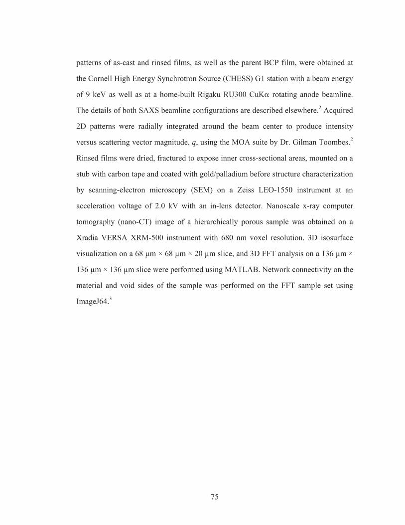
75
patterns of as-cast and rinsed films, as well as the parent BCP film, were obtained at
the Cornell High Energy Synchrotron Source (CHESS) G1 station with a beam energy
of 9 keV as well as at a home-built Rigaku RU300 CuK� rotating anode beamline.
The details of both SAXS beamline configurations are described elsewhere.2 Acquired
2D patterns were radially integrated around the beam center to produce intensity
versus scattering vector magnitude, q, using the MOA suite by Dr. Gilman Toombes.2
Rinsed films were dried, fractured to expose inner cross-sectional areas, mounted on a
stub with carbon tape and coated with gold/palladium before structure characterization
by scanning-electron microscopy (SEM) on a Zeiss LEO-1550 instrument at an
acceleration voltage of 2.0 kV with an in-lens detector. Nanoscale x-ray computer
tomography (nano-CT) image of a hierarchically porous sample was obtained on a
Xradia VERSA XRM-500 instrument with 680 nm voxel resolution. 3D isosurface
visualization on a 68 μm × 68 μm × 20 μm slice, and 3D FFT analysis on a 136 μm ×
136 μm × 136 μm slice were performed using MATLAB. Network connectivity on the
material and void sides of the sample was performed on the FFT sample set using
ImageJ64.3
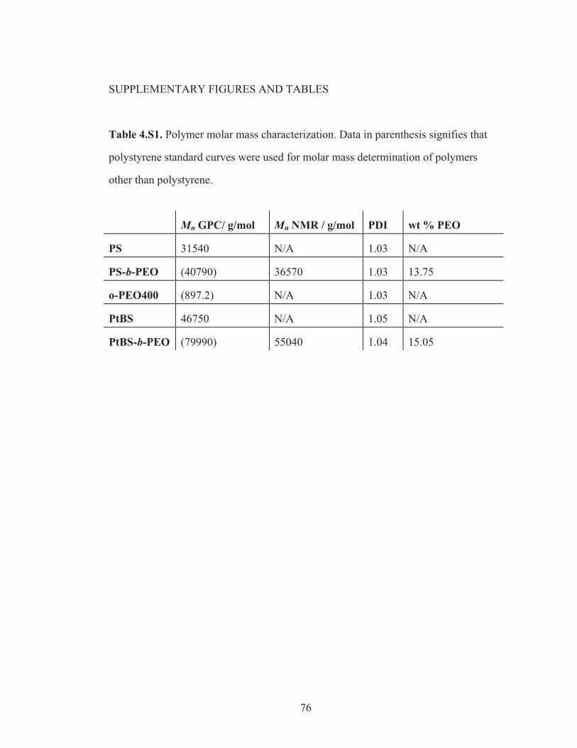
76
SUPPLEMENTARY FIGURES AND TABLES
Table 4.S1. Polymer molar mass characterization. Data in parenthesis signifies that
polystyrene standard curves were used for molar mass determination of polymers
other than polystyrene.
Mn GPC/ g/mol Mn NMR / g/mol PDI wt % PEO
PS 31540 N/A 1.03 N/A
PS-b-PEO (40790) 36570 1.03 13.75
o-PEO400 (897.2) N/A 1.03 N/A
PtBS 46750 N/A 1.05 N/A
PtBS-b-PEO (79990) 55040 1.04 15.05
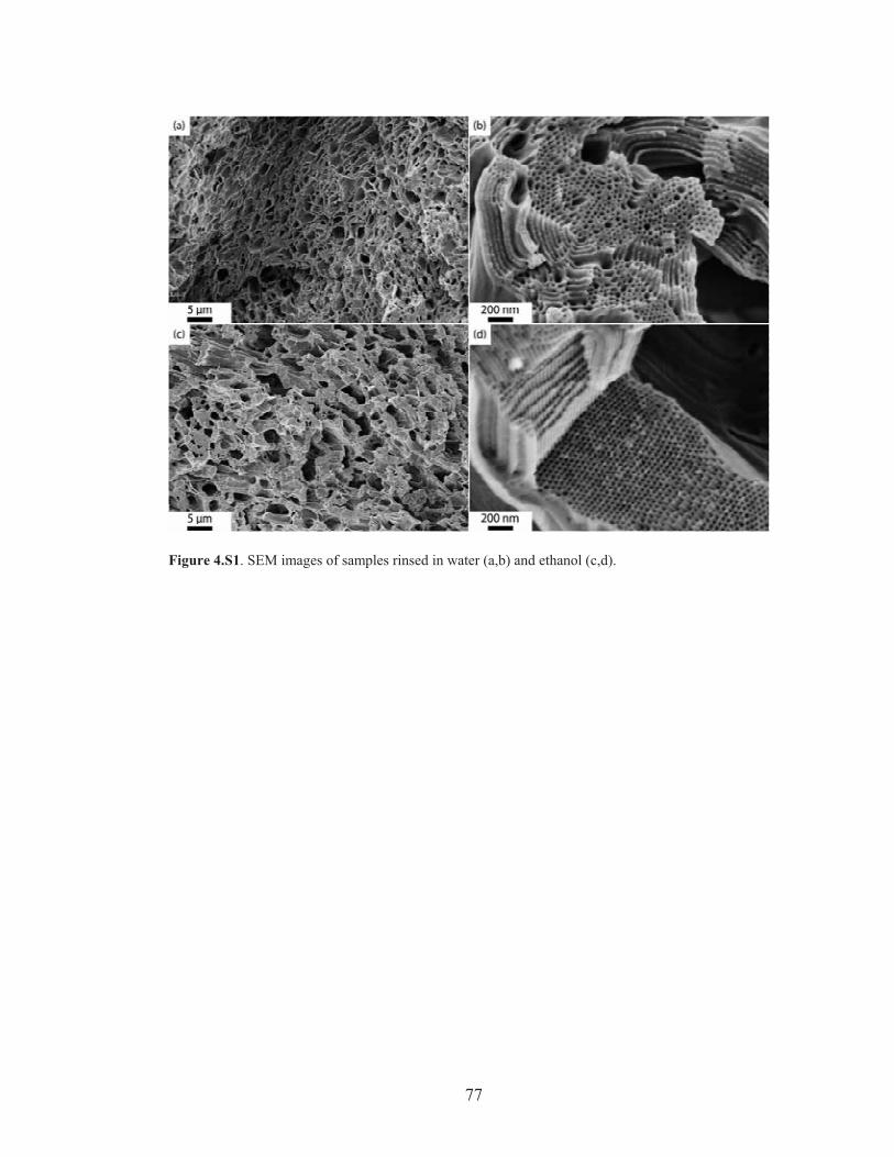
77
Figure 4.S1. SEM images of samples rinsed in water (a,b) and ethanol (c,d).
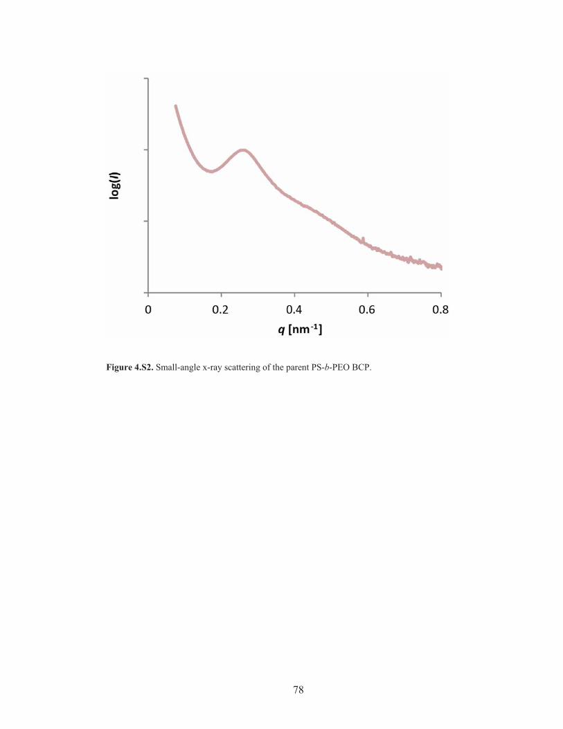
78
Figure 4.S2. Small-angle x-ray scattering of the parent PS-b-PEO BCP.
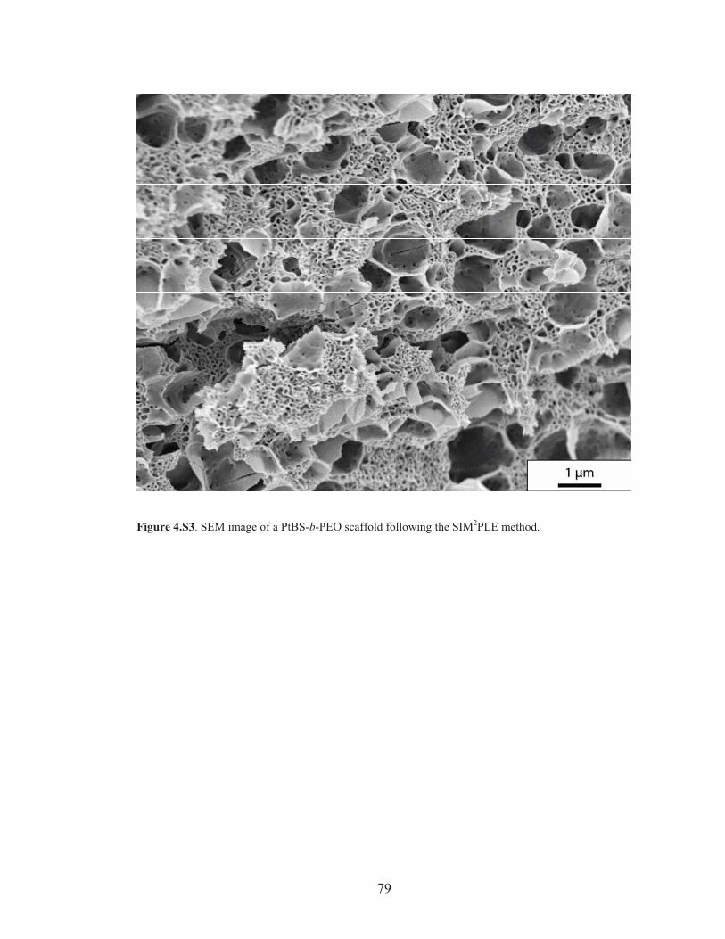
79
Figure 4.S3. SEM image of a PtBS-b-PEO scaffold following the SIM2PLE method.
80
REFERENCES
1. Floudas, G.; Ulrich, R.; Wiesner, U., J. Chem. Phys. 1999, 110 (1), 652-663. 2. Finnefrock, A. C.; Ulrich, R.; Toombes, G. E. S.; Gruner, S. M.; Wiesner, U., J. Am. Chem. Soc. 2003, 125 (43), 13084-13093. 3. Lee, T. C.; Kashyap, R. L.; Chu, C. N., CVGIP: Graphical Models and Image Processing 1994, 56 (6), 462-478.
81
CHAPTER 5
MORPHOLOGICAL CONTROL IN THE SYNTHESIS OF MACRO/MESO-
POROUS POLYMER SCAFFOLDS THROUGH SPINODAL DECOMPOSITION*
Abstract
Materials with connected porosity across multiple length scales are of
increasing interest as substrates for catalysis as well as scaffolds for other materials.
Here specific synthesis parameters were explored to produce hierarchically porous
polymer scaffolds using the spinodal-decomposition induced macro/meso-phase
separation plus extraction by rinsing (SIM2PLE) method applied to the block
copolymer/additive system poly(styrene-block-ethylene oxide) / oligo(ethylene oxide).
Final film thickness influenced structure homogeneity across the film. Film casting
temperature affected both the macro- and meso-scale pore structure, most notably
causing changes in the mesoscopic morphology. Additive molar mass variations
altered macropore size while mesostructure essentially stayed unaffected. Three
different casting solvents for the system were found for which the method provides
connected porosity across different length scales. The results provide design criteria
for block copolymer/oligomer blend-based hierarchically porous scaffold formation
via the SIM2PLE method.
* Sai, H.; Tan, K. W.; Gruner, S. M.; Wiesner, U. In preparation.
82
Introduction
Hierarchically porous materials with nanoscale features are of increasing
interest due to fast transport of media through the pores coupled with enhanced surface
area and improved mechanical stability.1, 2 Such materials have potential applications
in areas including membrane and separation science,3-5 catalysis,6-8 novel optical
material design,9, 10 and tissue engineering scaffolds for cell culture.11, 12 Various
processes have been developed to controllably fabricate such hierarchical structures,
including colloidal crystal templating or pre-patterned substrates with mesostructure-
forming precursors,13-17 ice or salt-crystal templating,18-20 and bio-templating.21, 22
Many of these approaches involve multiple steps, however, including backfilling of
preformed macroporous materials, thus suffering from a high level of complexity in
synthetic protocols.
The use of polymer blends to form bicontinuous structures by spinodal
decomposition has been widely studied as a viable approach to making polymer
mesostructures and macrostructures.23-28 As an example, polymeric bicontinuous
microemulsions, formed by blending an AB block copolymer (BCP) with A and B
oligomeric or polymeric additives, have been used as templates for backfilling with
another structure-directing material to yield hierarchical structures.29-32
Polymerization- and sol-gel induced phase separation has been applied to make
monolithic hierarchical structures of silica and carbon materials.33, 34 All-organic
three-dimensional hierarchical structures obtained from this approach have been
scarce in the literature, however.
BCP/additive blending has provided access to a large variety of morphologies
and inspired researchers to study, in depth, the theoretical and experimental aspects.26,
28, 35-43 The rich literature on the competition between macro- and micro-phase
separation suggests that by controlling the formation kinetics a region in phase-space
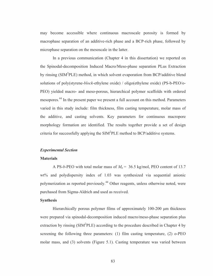
83
may become accessible where continuous macroscale porosity is formed by
macrophase separation of an additive-rich phase and a BCP-rich phase, followed by
microphase separation on the mesoscale in the latter.
In a previous communication (Chapter 4 in this dissertation) we reported on
the Spinodal-decomposition Induced Macro/Meso-phase separation PLus Extraction
by rinsing (SIM2PLE) method, in which solvent evaporation from BCP/additive blend
solutions of poly(styrene-block-ethylene oxide) / oligo(ethylene oxide) (PS-b-PEO/o-
PEO) yielded macro- and meso-porous, hierarchical polymer scaffolds with ordered
mesopores.44 In the present paper we present a full account on this method. Parameters
varied in this study include: film thickness, film casting temperature, molar mass of
the additive, and casting solvents. Key parameters for continuous macropore
morphology formation are identified. The results together provide a set of design
criteria for successfully applying the SIM2PLE method to BCP/additive systems.
Experimental Section
Materials
A PS-b-PEO with total molar mass of Mn = 36.5 kg/mol, PEO content of 13.7
wt% and polydispersity index of 1.03 was synthesized via sequential anionic
polymerization as reported previously.44 Other reagents, unless otherwise noted, were
purchased from Sigma-Aldrich and used as received.
Synthesis
Hierarchically porous polymer films of approximately 100-200 �m thickness
were prepared via spinodal-decomposition induced macro/meso-phase separation plus
extraction by rinsing (SIM2PLE) according to the procedure described in Chapter 4 by
screening the following three parameters: (1) film casting temperature, (2) o-PEO
molar mass, and (3) solvents (Figure 5.1). Casting temperature was varied between
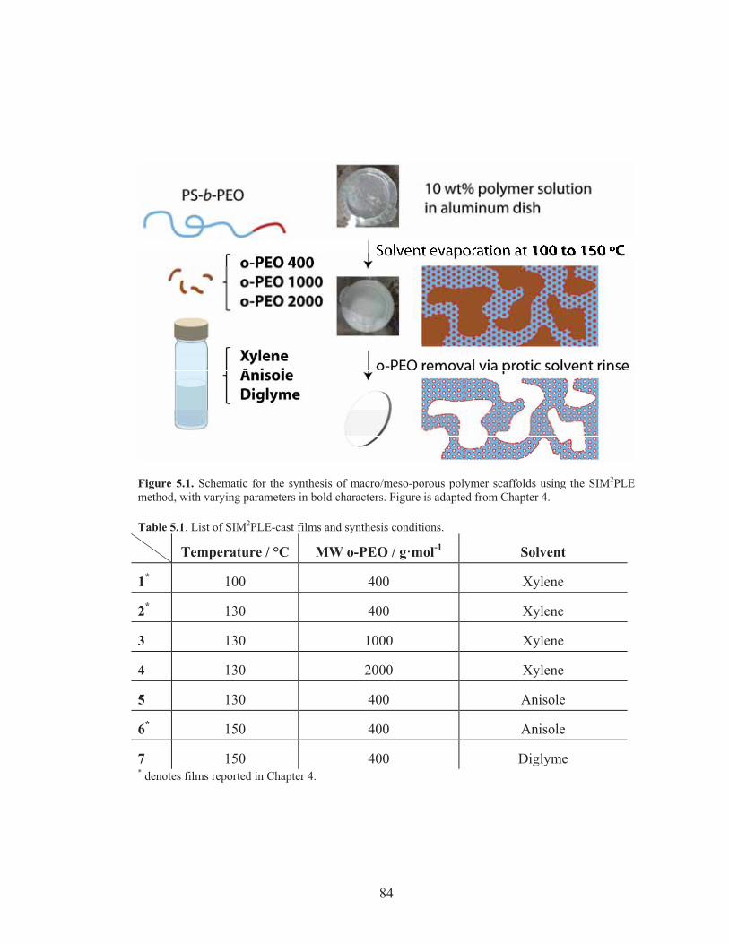
84
Figure 5.1. Schematic for the synthesis of macro/meso-porous polymer scaffolds using the SIM2PLE method, with varying parameters in bold characters. Figure is adapted from Chapter 4. Table 5.1. List of SIM2PLE-cast films and synthesis conditions.
Temperature / °C MW o-PEO / g·mol-1 Solvent
1* 100 400 Xylene
2* 130 400 Xylene
3 130 1000 Xylene
4 130 2000 Xylene
5 130 400 Anisole
6* 150 400 Anisole
7 150 400 Diglyme * denotes films reported in Chapter 4.
85
100 °C and 150 °C. Three dihydroxyl terminated PEO oligomers with molar masses of
400, 1000 and 2000 g/mol were employed as o-PEO additive. Xylene, anisole and
di(ethylene glycol) dimethyl ether (diglyme) were used as solvents. The weight ratio
between PS-b-PEO and o-PEO was kept constant at 1:1. Table 5.1 provides a list of all
films prepared together with their synthesis conditions. Solutions with 10 wt. %
polymer in the selected solvent were poured into aluminum dishes subjected to heating
on a hotplate covered with hemispherical glass chamber. We note that in xylene, o-
PEO precipitates at room temperature, but readily dissolves upon heating to 40 °C.
Film casting was completed within 1-2 hours, followed by rinsing in methanol at room
temperature to remove the additive as the final pore formation step.
In a separate experiment to investigate the effect of casting conditions on
macropore morphology, the BCP was dried to a pellet by heating in a vacuum oven at
200 °C for 3 days and used together with o-PEO400 obtained from a new bottle and
handled under dry nitrogen to minimize the effect of any residual water content. This
BCP/additive mixture was dissolved in xylene at 10 wt% and separated into four vials.
Water was added at 0.1 wt% of the total solution to two of the vials. The films were
then cast at 130 °C in aluminum dishes. One film with and one without additional
water were removed from the hotplate approximately 5 minutes after macrophase
separation became evident via strong film opacity, while the other two films were
heated continuously for one hour total.
Characterization
Scanning electron microscopy (SEM) images were acquired on a Zeiss LEO
1550 field emission microscope with acceleration voltage of 2.0 kV using an in-lens
detector. The samples were fractured to expose fresh cross-sections, mounted on
carbon tape and sputter coated with gold-palladium.
86
Transmission small-angle x-ray scattering (SAXS) patterns were obtained on a
home-built rotating anode beamline as well as at the G1 station of the Cornell High
Energy Synchrotron Source (CHESS). Details of the beamline setup are described
elsewhere.45
Results and Discussion
Effect of film casting environment on structural homogeneity and film morphology
In the SIM2PLE film formation process, upon heating and solvent evaporation
the block copolymer-additive mixture undergoes macroscopic phase separation into
BCP-rich and additive-rich domains as well as mesoscale ordering in the BCP-rich
phase/domains. The macrophase separation is visually observed by the onset of
opacity in the casting solution. By tracking the mass loss we determined that for 1:1
PS-b-PEO/o-PEO400 films, formation of such macroscopic phases occur when
polymer to solvent weight ratio becomes ~1:1. At a casting temperature of 130 °C
with xylene as solvent, this onset of macrostructure formation roughly corresponded to
a time point 5-10 minutes after the heating started.
The drying kinetics of films from polymer solutions is usually associated with
formation of an evaporation front skin from a polymer gel near the vapor/solution
interface, resulting in gradients in compositions from the film bottom to the
evaporation front.46-49 We have observed that when films of ~1 mm final thickness
were cast from solution (corresponding to ~10 mm in initial thickness), solvent
evaporation was blocked by the drying front causing significant vertical asymmetry in
the polymer/solvent composition (see Supporting Information, Figure 5.S1). This
could be suppressed by going to thinner films. Thus all subsequent films were cast to
form a final thickness of only ~ 200 �m, for which film asymmetry as observed in
87
cross-sections of the final films was minimized (see Supporting Information, Figure
5.S2, for comparison with thicker films).
We also originally noted that prolonged (4 hours or more) heating of the
samples led to gradual release of some vapor from the samples which appeared as
fogging on the hemispherical casting chamber wall after all casting solvent was gone.
Although the nature of the generated vapor is under investigation, we suspect that
water is forming as a result of condensation reactions between chain ends of the o-
PEO (the vapor pressure of o-PEO is negligible, especially for larger molar mass). As
higher molar mass o-PEO’s tend to exclude themselves from BCPs, the products of
such reactions could lead to undesired structural alterations. Thus the cast films were
quenched to room temperature at 1-2 hours after solvent evaporation was initiated.
Effect of casting temperature and solvents on pore structure
In addition to changes in the interaction parameters between PS and PEO
blocks in the melt state, adjusting the casting temperature can alter the interaction
between the PEO block and o-PEO, resulting in changes in the volume fraction
between the PS and PEO domains in the BCP-rich region. In the previous
communication, we have reported the formation of hexagonally packed inverse
cylinders and cubic structures on the mesoscale when films were cast at 130 and
100 °C, respectively (Chapter 4).
The formation of macroporosity in the solution casting process is induced by
the precipitation of o-PEO from the solution. Thus it is expected that if the additive
solubility can be tuned in the solution phase, it would lead to changes in the onset time
point for macrophase separation, which in turn can be used to tune the size of the final
macropores. Table 5.2 lists the solubility parameters and boiling points of the solvents
used in this study. Anisole was chosen as a direct comparison to xylene because of its
88
similarity in molecular structure with the exception of an additional ether group in
anisole. This leads to higher o-PEO solubility in anisole when compared to xylene.
Diethylene glycol dimethyl ether (diglyme) was chosen as the o-PEO-selective solvent
possessing a similar boiling point to anisole. Since anisole and diglyme both have
elevated boiling points, casting at higher temperatures was possible as compared to
what was used for the xylene-containing samples.
We have reported previously (see chapter 4) that at a casting temperature of
130 °C, anisole-cast films displayed similar macroporosity as well as mesoporosity to
xylene-cast films with similar channel-to-channel spacings. On the other hand, films
cast from anisole at 150 °C (Figure 5.2a-b) showed a drastically different morphology
than films cast from diglyme at 150 °C (Figure 5.2c-d). Small but irregularly sized
macropores (1-3 �m) with cell wall thickness close to the block copolymer length
scale (< 100 nm) were observed for anisole under these conditions (Figure 5.2a). No
mesostructures were apparent in such films (Figure 5.2b). In contrast, films cast from
diglyme at 150 °C showed an open cellular macropore structure (Figure 5.2c) with
cylindrical/lamellar mesostructures in the walls (Figure 5.2d).
The lack of mesostructure in the anisole-cast film at 150 °C coincides with the
observed delay in the onset of macrophase separation. The domain sizes of spinodal
decomposition are determined by the incompatibility of the components (quench
depth) and the polymer mobility. Since anisole is a good solvent for both PS and PEO
domains, the effective Flory-Huggins interaction parameter is lowered by dilution with
solvent. This induces a delay in the onset of macro- as well as meso-phase separation,
which in turn provides less time for macrophase restructuring and coarsening and
mesophase development. Diglyme provides an example of a selective solvent toward
the PEO block, inducing early macro- and meso-phase separation and allowing for
macrodomain coarsening similar to xylene.
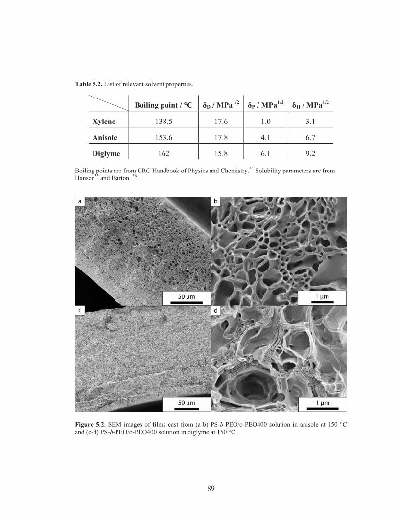
89
Table 5.2. List of relevant solvent properties.
Boiling point / °C �D / MPa1/2 �P / MPa1/2 �H / MPa1/2
Xylene 138.5 17.6 1.0 3.1
Anisole 153.6 17.8 4.1 6.7
Diglyme 162 15.8 6.1 9.2 Boiling points are from CRC Handbook of Physics and Chemistry.54 Solubility parameters are from Hansen55 and Barton. 56
Figure 5.2. SEM images of films cast from (a-b) PS-b-PEO/o-PEO400 solution in anisole at 150 °C and (c-d) PS-b-PEO/o-PEO400 solution in diglyme at 150 °C.
90
The above trends together with the results of our earlier study suggest that
casting temperature provides a handle on the mesoscale morphology while retaining
macroporosity in the resulting materials. Although choice of the solvent, xylene,
limited the usable temperature range to 138 °C, two distinct morphologies were
observed at two distinct temperatures, namely a cubic lattice with symmetry of aspect
4 at 100 °C, and a hexagonal lattice at 130 °C. For anisole as the solvent, a hexagonal
mesostructure in the walls was observed at 130 °C, while as shown here at 150 °C no
mesopores are discerned in the relatively thin walls of the final material. It is worth
noting that the shape of the macropores may be affected by the mesoscopic
morphology: hexagonally arranged channels, intrinsically anisotropic compared to
cubic mesostructures, can serve as a driving force for anisotropy in macropores, since
the o-PEO does not provide confinement on mesoscopic lattice growth. A similar
effect has been simulated and observed for PS-b-PI/PS blends with lamellar phases.40,
50
Effect of additive molar mass on pore structure
Homopolymer (HP) molar mass has been reported to affect the swelling
behavior of BCP domains.51 Mixing HPs that are larger than the compatible block of
the block copolymer leads to macrophase separation, while mixing of HPs with
smaller molar mass than the block of the BCP is generally considered entropically
favaroble.52 We hypothesize that o-PEO precipitates from the BCP system due to high
degrees of self-association in o-PEO via hydrogen bonding of the end-groups.53
Figure 5.3 shows a series of SEM images on BCP/o-PEO blends from different
molar mass o-PEOs cast from xylene at 130 °C. The film macrostructure (shown in
Figure 5.3a-c) suggests a slight increase in macropore size and broadening of pore size
distribution while the overall macroporosity seems to decrease. In contrast to the
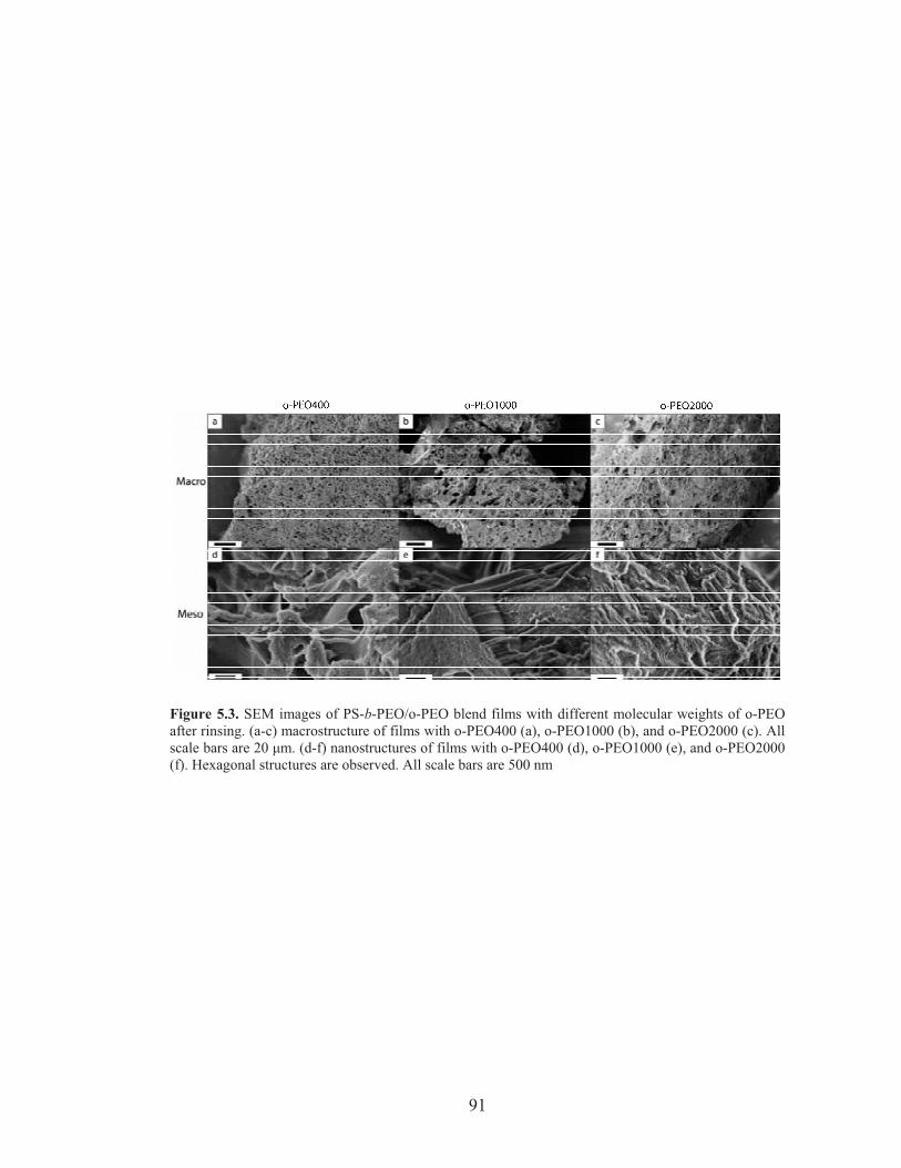
91
Figure 5.3. SEM images of PS-b-PEO/o-PEO blend films with different molecular weights of o-PEOafter rinsing. (a-c) macrostructure of films with o-PEO400 (a), o-PEO1000 (b), and o-PEO2000 (c). Allscale bars are 20 �m. (d-f) nanostructures of films with o-PEO400 (d), o-PEO1000 (e), and o-PEO2000(f). Hexagonal structures are observed. All scale bars are 500 nm
92
structural variation observed as a function of casting temperature reported earlier, the
BCP mesostructure (Figure 5.3d-f) did not show substantial changes as a function of
o-PEO molar mass but stayed hexagonal in all cases. When o-PEO with a molar mass
of 6000 g/mol was used (data not shown), i.e. slightly larger than the PEO block size
of the PS-b-PEO, a clear film with two visually distinguishable domains formed,
indicating complete macrophase separation.
Coarsening of the macrostructure with larger o-PEO’s can be explained by the
increased incompatibility between the PEO block and the additive o-PEO: as they
become less compatible macrophase separation occurs earlier along the
evaporation/heating timeline, allowing macrodomains to merge and grow. It is
interesting that in contrast to the macrostructure, the film mesostructure does not
considerably change when using additives with varying mixing limits. More detailed
studies such as changing the end group functionalities in the PEO chains and
observing the degree of association between o-PEO and BCP PEO domains vs. self-
association of o-PEO would be needed, however, to better understand this
phenomenon.
Effect of residual water and casting time on film formation kinetics
We finally note that casting duration and residual water content in the solution
synergistically affect the resulting film morphology. After 3 to 4 months since the first
sets of films were synthesized, including the seven films described in Table 5.1, we
observed that the same experimental procedure failed to produce the networked
macroporous structure, but instead lead to the formation of an isolated spherical/closed
cellular macroporous structure (see Supporting Information, Figure 5.S3). In order to
determine key parameters responsible for this change in the kinetically trapped
morphology, we introduced a controlled amount of water and obtained two time points
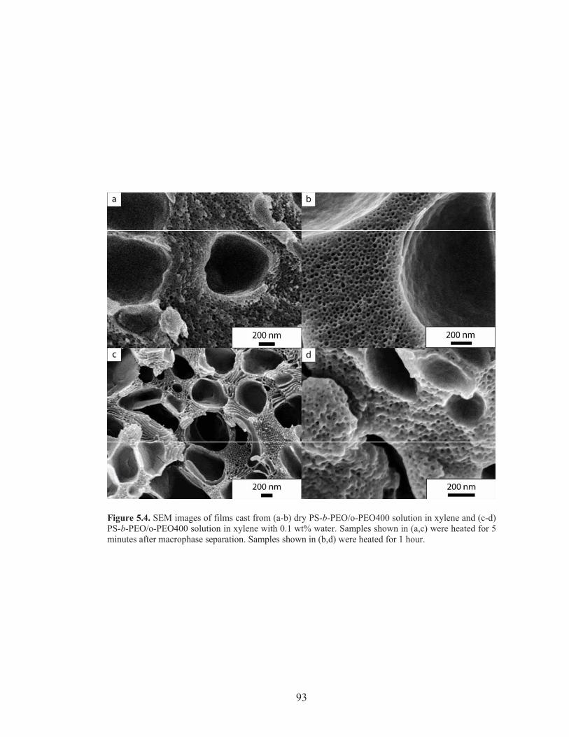
93
Figure 5.4. SEM images of films cast from (a-b) dry PS-b-PEO/o-PEO400 solution in xylene and (c-d)PS-b-PEO/o-PEO400 solution in xylene with 0.1 wt% water. Samples shown in (a,c) were heated for 5minutes after macrophase separation. Samples shown in (b,d) were heated for 1 hour.
94
for water-free and water-containing films. Only the film that contained 0.1 wt% water
in the solution and was heated for a short timeshowed the network macroporous
structure (Figure 5.4). While these results point to the importance of water in the
SIM2PLE process in particular in the presence of PEO, further studies on how water
content and other parameters not studied here affect the structure formation kinetics in
detail are underway.
Design criteria for hierarchical structure formation through SIM2PLE process
The above set of experiments indicates that mesostructure formation is largely
dominated by factors such as temperature and volume fraction, while macrostructure
formation is strongly affected by factors such as quench depth (supersaturation) and
polymer mobility. From our results a number of requirements for successful
hierarchical structure formation using the SIM2PLE process can be identified:
1, The BCP matrix block should be glassy at room temperature but rubbery at
the casting temperature: In order to provide mechanical stability after solvent
evaporation and additive removal, the BCP has to be glassy at room temperature.
However, mobility at casting temperature is required to provide equilibration in the
mesophase.
2, The additive-rich phase should phase-separate from the neat block
copolymer phase while maintaining appreciable solubility in the block copolymer
phase: In order to provide mesoporosity after film rinsing, a considerable amount of
additive should stay in the BCP-rich phase. In our case, o-PEO with a smaller molar
mass than the BCP PEO block satisfied this condition by the self-associating nature of
hydroxyl-terminated o-PEO.
3, The solvent should be chosen such that the quench depth or supersaturation
of the metastable polymer solution is suitable for forming macrostructures on the �m
95
length scale: smaller macrophase separation length scales limit the BCP-rich phase
from forming well-defined morphologies and prevent long-range order formation,
while excessive coarsening of the macrostructure can result in film inhomogeneity.
Conclusion
A set of synthesis parameters in the SIM2PLE process, including casting
temperature, film thickness, o-PEO molar mass, and casting solvent, have been varied
to study their effects on the hierarchical macro/meso-scale structure. Of these
parameters, changing the casting temperature resulted in mesostructural
transformations from hexagonal to cubic lattices to no mesostructure in the walls,
while changes in the o-PEO molar mass and casting solvent caused variations in the
kinetics of macrophase separation and coarsening of the macroscopic domains, thus
altering the macroporosity in the final films. Film thickness variations changed the
homogeneity of film structure. Other parameters, such as BCP molar mass, casting
speed, water content (in particular in the presence of PEO), and polymer chemical
functionality to tailor enthalpic interactions, need further studies to gain a deeper
understanding of the structure formation within these films. The results provide design
criteria for the successful hierarchically structure formation of hierarchical polymer
scaffolds from BCP/additive blends using the SIM2PLE process.
Acknowledgment
This work was supported by the National Science Foundation (NSF) Single
Investigator Award (DMR-1104773). This work made use of the SEM facility of the
Cornell Center for Materials Research (CCMR) with support from the National
Science Foundation Materials Research Science and Engineering Centers (MRSEC)
program (DMR-1120296), and the Cornell High Energy Synchrotron Source (CHESS),

96
which is supported by the NSF and the National Institutes of Health/National Institute
of General Medical Sciences under NSF award DMR-0936384.
97
REFERENCES 1. Lakes, R., Nature 1993, 361 (6412), 511-515. 2. Innocenzi, P.; Malfatti, L.; Soler-Illia, G. J. A. A., Chem. Mater. 2011, 23 (10), 2501-2509. 3. Hillmyer, M., Nanoporous Materials from Block Copolymer Precursors. In Block Copolymers II, 2005; pp 137-181. 4. Peinemann, K.-V.; Abetz, V.; Simon, P. F. W., Nat. Mater. 2007, 6 (12), 992-996. 5. Phillip, W. A.; Dorin, R. M.; Werner, J.; Hoek, E. M. V.; Wiesner, U.; Elimelech, M., Nano Lett. 2011, 11 (7), 2892-2900. 6. van Donk, S.; Janssen, A. H.; Bitter, J. H.; de Jong, K. P., Catalysis Reviews-Science and Engineering 2003, 45 (2), 297-319. 7. Yu, J.; Su, Y.; Cheng, B., Adv. Funct. Mater. 2007, 17 (12), 1984-1990. 8. Li, Y.; Sasaki, T.; Shimizu, Y.; Koshizaki, N., J. Am. Chem. Soc. 2008, 130 (44), 14755-14762. 9. Huang, Y.; Lieber, C. M., Pure Appl. Chem. 2004, 76 (12), 2051-2068. 10. Stein, A.; Li, F.; Denny, N. R., Chem. Mater. 2008, 20 (3), 649-666. 11. Bechtle, S.; Ang, S. F.; Schneider, G. A., Biomaterials 2010, 31 (25), 6378-6385. 12. Dankers, P. Y. W.; Boomker, J. M.; Huizinga-van der Vlag, A.; Wisse, E.; Appel, W. P. J.; Smedts, F. M. M.; Harmsen, M. C.; Bosman, A. W.; Meijer, W.; van Luyn, M. J. A., Biomaterials 2011, 32 (3), 723-733. 13. Yang, P. D.; Deng, T.; Zhao, D. Y.; Feng, P. Y.; Pine, D.; Chmelka, B. F.; Whitesides, G. M.; Stucky, G. D., Science 1998, 282 (5397), 2244-2246. 14. Rhodes, K. H.; Davis, S. A.; Caruso, F.; Zhang, B. J.; Mann, S., Chem. Mater. 2000, 12 (10), 2832-+. 15. Yu, S. H.; Colfen, H., J. Mater. Chem. 2004, 14 (14), 2124-2147. 16. Zhang, G.; Wang, D. Y.; Gu, Z. Z.; Mohwald, H., Langmuir 2005, 21 (20), 9143-9148. 17. Kamperman, M.; Burns, A.; Weissgraeber, R.; van Vegten, N.; Warren, S. C.; Gruner, S. M.; Baiker, A.; Wiesner, U., Nano Lett. 2009, 9 (7), 2756-2762. 18. Lu, A. H.; Li, W. C.; Schmidt, W.; Schuth, F., Microporous Mesoporous Mater. 2006, 95 (1-3), 187-192. 19. Khan, F.; Walsh, D.; Patil, A. J.; Perriman, A. W.; Mann, S., Soft Matter 2009, 5 (16), 3081-3085. 20. Mori, H.; Aotani, K.; Sano, N.; Tamon, H., J. Mater. Chem. 2011, 21 (15), 5677-5681. 21. Chen, Y.; Gu, J.; Zhang, D.; Zhu, S.; Su, H.; Hu, X.; Feng, C.; Zhang, W.; Liu, Q.; Parker, A. R., J. Mater. Chem. 2011, 21 (39), 15237-15243. 22. Cho, K.; Na, K.; Kim, J.; Terasaki, O.; Ryoo, R., Chem. Mater. 2012. 23. Cahn, J. W., J. Chem. Phys. 1965, 42 (1), 93-&. 24. Bates, F. S., Science 1991, 251 (4996), 898-905.
98
25. Bates, F. S.; Maurer, W. W.; Lipic, P. M.; Hillmyer, M. A.; Almdal, K.; Mortensen, K.; Fredrickson, G. H.; Lodge, T. P., Phys. Rev. Lett. 1997, 79 (5), 849-852. 26. Floudas, G.; Hadjichristidis, N.; Stamm, M.; Likhtman, A. E.; Semenov, A. N., J. Chem. Phys. 1997, 106 (8), 3318-3328. 27. Fredrickson, G. H.; Bates, F. S., J. Polym. Sci., Part B: Polym. Phys. 1997, 35 (17), 2775-2786. 28. Likhtman, A. E.; Semenov, A. N., Macromolecules 1997, 30 (23), 7273-7278. 29. Fleury, G.; Bates, F. S., Soft Matter 2010, 6 (12), 2751-2759. 30. Jones, B. H.; Lodge, T. P., Chem. Mater. 2010, 22 (4), 1279-1281. 31. Jones, B. H.; Lodge, T. P., Chem. Mater. 2011, 23 (21), 4824-4831. 32. Jones, B. H.; Lodge, T. P., ACS Nano 2011, 5 (11), 8914-8927. 33. Nakanishi, K.; Amatani, T.; Yano, S.; Kodaira, T., Chem. Mater. 2008, 20 (3), 1108-1115. 34. Liang, C.; Dai, S., Chem. Mater. 2009, 21 (10), 2115-2124. 35. Whitmore, M. D.; Noolandi, J., Polym. Eng. Sci. 1985, 25 (17), 1120-1121. 36. Hashimoto, T.; Kimishima, K.; Hasegawa, H., Macromolecules 1991, 24 (20), 5704-5712. 37. Semenov, A. N., Macromolecules 1993, 26 (9), 2273-2281. 38. Izumitani, T.; Hashimoto, T., Macromolecules 1994, 27 (7), 1744-1750. 39. Matsen, M. W., Phys. Rev. Lett. 1995, 74 (21), 4225-4228. 40. Ohta, T.; Ito, A., Phys. Rev. E 1995, 52 (5), 5250-5260. 41. Lee, J. H.; Balsara, N. P.; Chakraborty, A. K.; Krishnamoorti, R.; Hammouda, B., Macromolecules 2002, 35 (20), 7748-7757. 42. Martinez-Veracoechea, F. J.; Escobedo, F. A., Macromolecules 2009, 42 (22), 9058-9062. 43. Martinez-Veracoechea, F. J.; Escobedo, F. A., Macromolecules 2009, 42 (5), 1775-1784. 44. Sai, H.; Tan, K. W.; Gruner, S. M.; Wiesner, U., In preparation. 45. Finnefrock, A. C.; Ulrich, R.; Toombes, G. E. S.; Gruner, S. M.; Wiesner, U., J. Am. Chem. Soc. 2003, 125 (43), 13084-13093. 46. Vrentas, J. S.; Vrentas, C. M., J. Polym. Sci., Part B: Polym. Phys. 1994, 32 (1), 187-194. 47. Vrentas, J. S.; Vrentas, C. M., J. Appl. Polym. Sci. 1996, 60 (7), 1049-1055. 48. Alsoy, S.; Duda, J. L., Drying Technol. 1998, 16 (1-2), 15-44. 49. Okuzono, T.; Ozawa, K.; Doi, M., Phys. Rev. Lett. 2006, 97 (13). 50. Koizumi, S.; Hasegawa, H.; Hashimoto, T., Macromolecules 1994, 27 (22), 6532-6540. 51. Abetz, V.; Simon, P., Phase Behaviour and Morphologies of Block Copolymers. In Block Copolymers I, 2005; pp 125-212. 52. Jiang, M.; Xie, H. K., Prog. Polym. Sci. 1991, 16 (6), 977-1026. 53. Sarkar, A.; Ghosh, K., Kolloid-Zeitschrift and Zeitschrift Fur Polymere 1970, 236 (2), 140-142. 54. CRC handbook of chemistry and physics. 1978. 55. Hansen, C. M. Ind. Eng. Chem. Prod. Res. Dev. 1969, 8 (1), 2-11.

99
56. Barton, A. F. M., Chem. Rev. 1975, 75 (6), 731-753.
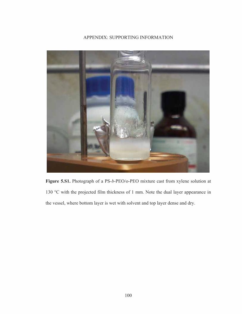
100
APPENDIX: SUPPORTING INFORMATION
Figure 5.S1. Photograph of a PS-b-PEO/o-PEO mixture cast from xylene solution at
130 °C with the projected film thickness of 1 mm. Note the dual layer appearance in
the vessel, where bottom layer is wet with solvent and top layer dense and dry.
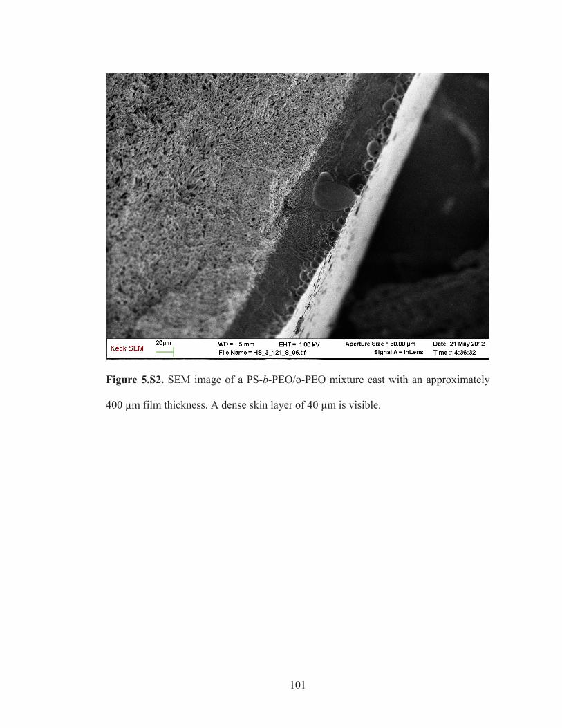
101
Figure 5.S2. SEM image of a PS-b-PEO/o-PEO mixture cast with an approximately
400 μm film thickness. A dense skin layer of 40 μm is visible.
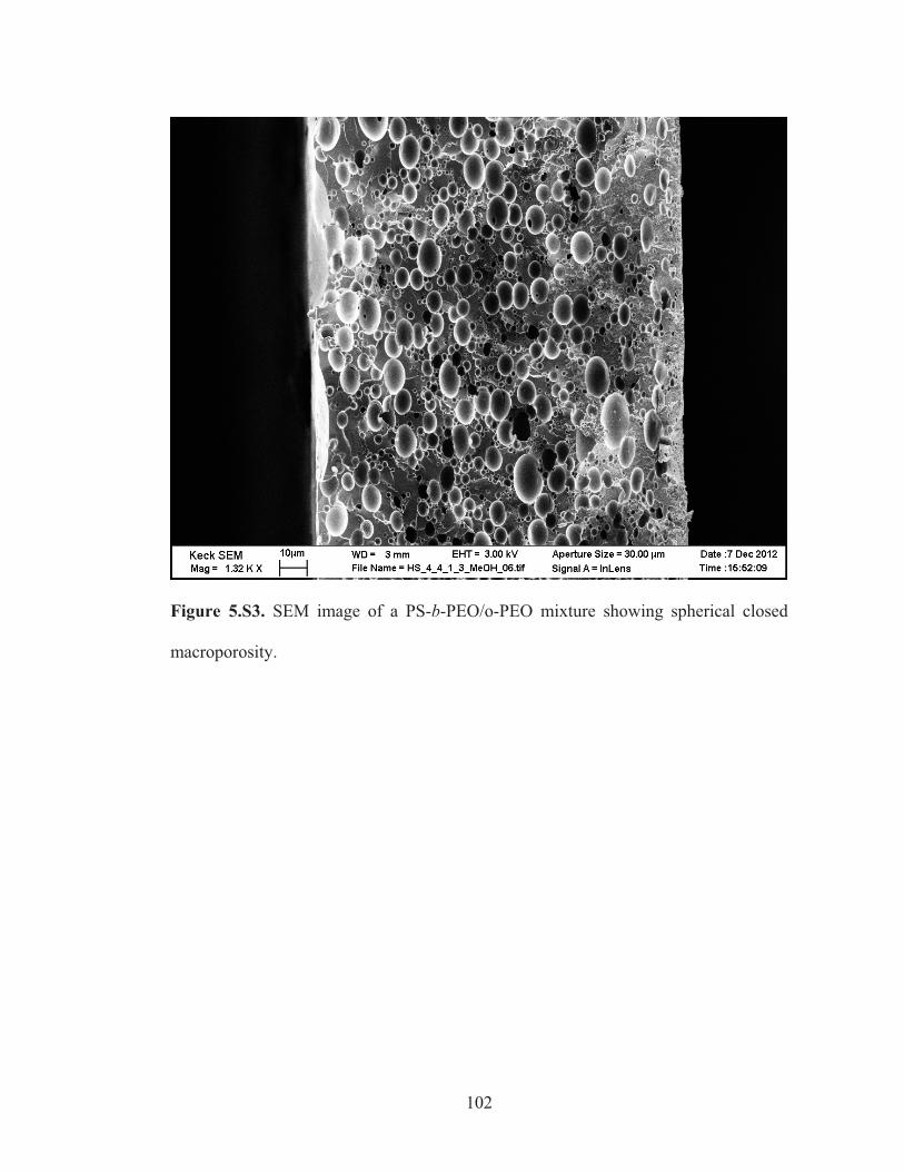
102
Figure 5.S3. SEM image of a PS-b-PEO/o-PEO mixture showing spherical closed
macroporosity.
103
CHAPTER 6
CONCLUSION
In this dissertation, I have explored various facets of complexity in synthetic
self-assembly nanomaterials: multicompartment nanoparticles (Chapter 2),
multicomponent organic/inorganic hybrid materials (Chapter 3), and hierarchically
porous polymer scaffolds (Chapters 4 and 5).
In Chapter 2, a new type of mesoporous silica nanoparticle was synthesized
and characterized containing multiple mesoscopic lattices within a single particle,
referred to as multi-MSNs. Ethyl acetate concentration in the reaction feed was
identified as a key parameter for controlling multi-MSN morphologies.
In Chapter 3, organic/inorganic hybrid nanomaterials from the amphiphilic
block copolymer PI-b-PDMAEMA and Pt NPs were synthesized and characterized.
Study of the ligand density on the nanoparticle surface revealed possible interactions
between free metal surface and aminated polymer side-chains. Changing the ratio of
BCP to NP resulted in a variety of mesostructures, some of which could subsequently
be dissociated into nano-objects via selective dissolution of the matrix PI block.
In Chapters 4 and 5, hierarchically porous three-dimensional polymer scaffolds
were synthesized via the SIM2PLE method. Spinodal decomposition of the
BCP/additive mixtures resulted in macrostructure formation accompanied by
microphase separation of the BCP-rich domains resulting in ordered mesostructures. A
facile washing step with protic solvents yielded the final porous polymer scaffolds.
Design criteria for the synthetic method with control over mesopore lattices and
macropore sizes were identified.
104
In summary, I have shown that by fine-tuning the building block compositions
and thermodynamic synthesis conditions, one can design and prepare potentially
functional nanomaterials via bottom-up-type self-assembly approaches common in
biological systems.
One can extrapolate this work to various future directions by combining
multiple of the features observed. For example, in conjunction with multicompartment
and multicomponent materials, a drug delivery system where different compartments
in the multi-MSNs are loaded with different drug molecules would be an interesting
application. Between multicompartment and multi-length scale features, BCPs that can
incorporate MSNs in one block would constitute a hierarchically structured catalytic
support that would prevent clogging and caking of side-products on small pores.
Finally, incorporating inorganic nanoparticles in SIM2PLE scaffolds or backfilling of
the scaffolds with deposition processes can lead to multicomponent hierarchical
structures.