Structural and electrochemical characterization of carbon electrode modified by multi-walled carbon...
31
Accepted Manuscript Title: Structural and Electerochemical Characterization of Carbon Electrode Modified by Multi-Walled Carbon Nanotubes and Surfactant Authors: Elmira Pajootan Mokhtar Arami PII: S0013-4686(13)01734-9 DOI: http://dx.doi.org/doi:10.1016/j.electacta.2013.09.012 Reference: EA 21229 To appear in: Electrochimica Acta Received date: 1-7-2013 Revised date: 3-9-2013 Accepted date: 3-9-2013 Please cite this article as: E. Pajootan, M. Arami, Structural and Electerochemical Characterization of Carbon Electrode Modified by Multi- Walled Carbon Nanotubes and Surfactant, Electrochimica Acta (2013), http://dx.doi.org/10.1016/j.electacta.2013.09.012 This is a PDF file of an unedited manuscript that has been accepted for publication. As a service to our customers we are providing this early version of the manuscript. The manuscript will undergo copyediting, typesetting, and review of the resulting proof before it is published in its final form. Please note that during the production process errors may be discovered which could affect the content, and all legal disclaimers that apply to the journal pertain.
Transcript of Structural and electrochemical characterization of carbon electrode modified by multi-walled carbon...
Accepted Manuscript
Title: Structural and Electerochemical Characterization ofCarbon Electrode Modified by Multi-Walled CarbonNanotubes and Surfactant
Authors: Elmira Pajootan Mokhtar Arami
PII: S0013-4686(13)01734-9DOI: http://dx.doi.org/doi:10.1016/j.electacta.2013.09.012Reference: EA 21229
To appear in: Electrochimica Acta
Received date: 1-7-2013Revised date: 3-9-2013Accepted date: 3-9-2013
Please cite this article as: E. Pajootan, M. Arami, Structural andElecterochemical Characterization of Carbon Electrode Modified by Multi-Walled Carbon Nanotubes and Surfactant, Electrochimica Acta (2013),http://dx.doi.org/10.1016/j.electacta.2013.09.012
This is a PDF file of an unedited manuscript that has been accepted for publication.As a service to our customers we are providing this early version of the manuscript.The manuscript will undergo copyediting, typesetting, and review of the resulting proofbefore it is published in its final form. Please note that during the production processerrors may be discovered which could affect the content, and all legal disclaimers thatapply to the journal pertain.
Page 1 of 30
Accep
ted
Man
uscr
ipt
Structural and Electerochemical Characterization of Carbon Electrode Modified by Multi-Walled Carbon Nanotubes and Surfactant
Elmira Pajootan1, Mokhtar Arami2∗
1Textile Engineering Department, Amirkabir University of Technology,424 Hafez Ave, Tehran, Iran, 15875-4413. Tel: +982164542614, Fax: +98 2166400245, E-mail: [email protected]
2Textile Engineering Department, Amirkabir University of Technology,424 Hafez Ave, Tehran, Iran, 15875-4413. Tel: +982164542614, Fax: +98 2166400245, E-mail: [email protected]
Abstract
In this study, multi-walled carbon nanotubes were successfully deposited on the surface of
the carbon electrode (CE) using a cationic surfactant (Cetyl Trimethyl Ammonium Bromide,
CTAB) by simple electrodeposition method. FT-IR spectra, SEM images and the contact angle
measurements were employed to characterize the structure of the modified electrode. The
electrochemical impedance spectroscopy and cyclic voltammetry were performed to evaluate the
electroanalytical behavior of electrodes through the modification process. The results indicated
that the impedance of the modified electrode was reduced about 95% at pH 3 and 7.4 and 91% at
pH 11 due to the deposition of the nanotubes on its surface. The equivalent circuit for EIS
measurements was perfectly fitted at three pH values (3, 7.4 and 11) on the basis of the
transmission line model that represents the impedance response of a diffusion process to
characterize the properties of the bulk films. Also, the electrochemical behavior of methylene
blue on the surface of the modified electrode was investigated. The obtained cyclic
voltammograms showed three redox peaks, which can be related to the formation of semi-
methylene blue and leucomethylene blue.
Keywords: Multi-Walled Carbon Nanotubes, Electrodeposition, Electrochemical Impedance Spectroscopy, Cyclic Voltammetry, Transmission Line Model.
∗ Author to whom all correspondence should be addressed: 424 Hafez Ave, Tehran, Iran, 15875-4413. Tel: +98 //2164542614, Fax: +98 2166400245, Email: [email protected].
Page 2 of 30
Accep
ted
Man
uscr
ipt
1. Introduction
Electrode material based on carbonaceous compounds has been widely applied in
electrochemistry and electroanalysis as working electrode due to their special properties
including low resistivity, chemical inertness, and unique surface chemistry, which make them a
proper choice to determine a wide range of substances in electrocatalytic area [1-7]. Also carbon
electrodes (CEs) have the advantage of having a larger hydrogen overvoltage rather than metals
[8]. Various types of CEs such as carbon paste [9, 10], carbon fiber [11], glassy carbon [12],
screen-printed carbon [13], carbon nanotubes (CNTs) [14, 15], etc. have been developed and/or
modified to achieve specific properties for a variety of electrochemical purposes.
The nano-scale structure, large surface area, high mechanical strength and extraordinary
electronic properties of CNTs have made them useful in several attractive applications including
nanosized semiconductor devices, high performance nanocomposites, energy conversion
devices, sensors, etc [14, 15]. The modification of electrodes using multi-walled carbon
nanotubes (MWCNTs) to design new analytical sensors has been prevalently reported [16-20].
Homogenous and consistent coating of CNTs on the surface of the electrodes can be attained by
simple, low cost and feasible electrodeposition method followed by the uniform dispersing of
electrically charged CNTs [21].
The previous investigations reported that the CNTs have been negatively or positively
charged by carboxylic or amino functionalization which helps disperse individual CNTs in the
suspension for electrodeposition process [22, 23]. Also several studies have surveyed the
electrodeposition of the combination of CNTs/metal ions or CNTs/metal oxides on the surface of
various electrode substrates [24-27].
Another appropriate and simple method to overcome the poor solubility of CNTs to attain the
stable dispersion is the application of surfactants. In this procedure, the surfactant is adsorbed on
the surface of CNTs, and subsequent ultrasonication of the solution, which takes several minutes,
will cleave apart their aggregations and debundle nanotubes by steric or electrostatic repulsions
resulted from the charge of surfactant hydrophilic groups [28-30].
In this paper, MWCNTs have been electrodeposited by applying direct current onto the CE
under ambient conditions in mild solution with high efficiency. The electrodeposition solution
contained MWCNTs and a cationic surfactant (Cetyl Trimethyl Ammonium Bromide, CTAB)
that sonicated for 60 min. The literature reviews indicated that the dispersion of MWCNTs via
Page 3 of 30
Accep
ted
Man
uscr
ipt
cationic surfactant and further fabrication of CEs by electrodeposition has not yet been
investigated. Surface morphology and structure of the prepared electrodes were studied using
scanning electron microscope (SEM). The dynamic contact angle of the electrodes was also
measured to determine the hydrophilicity of the surface. FT-IR analysis was employed to
compare the surface groups of the electrode before and after the deposition. Furthermore, in the
current study, the electrochemical properties of the electrodes during different steps of
preparation have been illustrated. The electrochemical impedance spectroscopy of electrodes was
carried out to understand the transport and reaction processes occurring in the film; and the
transmission line model to describe the diffusive layer allowed for a satisfactory description of
the data obtained. The cyclic voltammetry was also established to investigate the determination
of the organic 3,7-bis(dimethylamino)phenothiazine-5-ium-chloride as the model dye
(Methylene Blue, MB) in aqueous solutions by modified electrode. MB has been widely utilized
in electrocatalysis and electrochromics; and there are many redox reactions available to MB [31].
Finally, a mechanism was proposed for the reaction of MB on the surface of the modified
electrode.
2. Materials and methods
2.1. Chemicals and materials
In all experiments the reagents used were of analytical grade. Cetyl Trimethyl Ammonium
Bromide ((C16H33)N(CH3)3Br, CTAB) and multi-walled carbon nanotubes (MWCNTs) (purity>
95%, length 10-20 μm and diameter 30-50 nm) were purchased from Merck and Neutrino,
respectively. C.I. Basic Blue 9 (Methylene Blue, MB) was obtained from Ciba Co. Buffer
solutions including pH 3 (citrate and hydrochloric acid), pH 7.4 (phosphate buffer solution) and
pH 11 (boric acid, potassium chloride and sodium hydroxide), all with the conductivity of 6
mS/cm were also purchased from Merck.
2.2. Preparation of the modified electrode
Prior to modification, carbon electrodes (graphite with the dimension of 3×20×80 mm3) were
hand-polished with emery paper, then washed with distilled water and pretreated with NaOH
(10%), HNO3: H2O (1:1, v/v) and acetone, each for 5 min, respectively. Finally the electrodes
(pretreated-CE) were rinsed with distilled water. The electrode modification by electrodeposition
Page 4 of 30
Accep
ted
Man
uscr
ipt
method was carried out by applying DC voltage of 17.5 (V) to the solution containing 0.3 g/L
MWCNTs and 0.2 g/L CTAB, which was sonicated for 60 min using Delta D68H Ultrasonic.
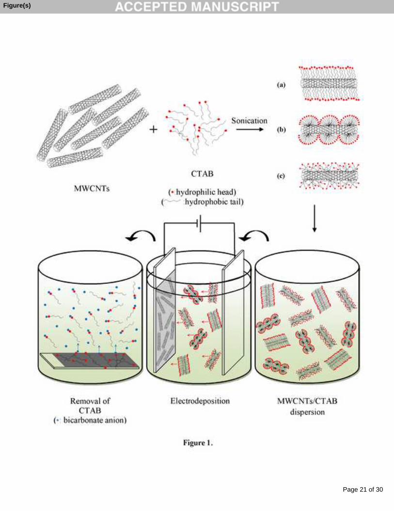
The ultrasonication of MWCNTs via CTAB will lead to the dispersion of nanotubes, and fix the
surfactants on the surface of MWCNTs (possible arrangements of CTAB on MWCNTs are
illustrated in Fig. 1(a), (b) and (c) [28]). It can be described that the cationic surfactant will make
the nanotubes positively charged; and through simple electrodeposition process, these charged
CNTs are driven toward cathode to form a thin layer at the electrode surface.
Eventually, the coated electrodes (MWCNTs/CTAB-CE) were immersed in the bicarbonate
solution (0.01 M) for 30 min in order to extract the residual surfactants from the surface of
electrode. The modified electrodes were washed with distilled water and dried in room
temperature (MWCNTs-CE). The modification steps are schematically shown in Fig. 1. In this
study, the structural as well as the electrochemical characterization of the modified electrode
(MWCNTs-CE) in the course of the preparation processes have been investigated.
Figure 1.
2.3. Characterization of the modified electrode
The Fourier transform infrared (FT-IR) spectroscopy of CE, pretreated CE,
MWCNTs/CTAB-CE and MWCNTs-CE were measured with a Thermo Nicolet Avatar 360 FT-
IR Spectrometer within the range of 500- 4000 cm-1.
The surface morphology of CE at different steps of modification was observed using a field
emission scanning electron microscope ((FESEM) JSM-6700F, JEOL, Japan) operated at the
voltage of 20.0 kV.
Dynamic contact angle of the electrodes were measured using KRŰSS processor tensiometer
K100 MK2/SF/C (Germany) to investigate the surface hydrophobicity to confirm the suggested
modification mechanism.
Impedance measurements were carried out in a three-electrode system made by Ivium
Compactstat (Eindhoven, the Netherlands). A saturated calomel electrode (SCE) and graphite
rod were used as a reference and auxiliary electrodes, respectively. The software used for
determining the equivalent circuit and data analysis was Ivium Equivalent Circuit Evaluator
Page 5 of 30
Accep
ted
Man
uscr
ipt
(Eindhoven, the Netherlands). EIS was measured in solutions with pH of 3, 7.4 and 11 at 25 ˚C.
The frequency was varied in the range of 100 Hz to 106 Hz.
The cyclic voltammetry (CV) was performed in a three-electrode cell with Ag/AgCl as
reference electrode and Pt as the counter electrode. CV was once made in solutions with pH of 3,
7.4 and 11 to study the capacitive behavior of electrodes and once in solution containing MB and
Fe3+ to determine MB in the solution, between the potentials of -0.6 V and +0.8 V (vs. Ag/AgCl)
at scan rate of 50 mV/s.
3. Results and discussions
3.1. Structural characterization of the electrodes
The contact angle is the angle where a liquid/vapor interface meets a solid surface, which
quantifies the wettability of a solid surface by a liquid via the Young’s equation [32, 33].
γsv = γsl.Cos θ + γsl (1)
where γsv, γsl and θ are the solid surface free energy, solid/liquid interfacial free energy and
contact angle, respectively.
In this study the dynamic contact angle of the electrode surface with water has been
evaluated, when the electrode is entering the water (advancing contact angle). In this regard,
samples of electrodes with the dimension of 1×10×20 mm3 were prepared and entered into the
water container by a holder. As a result of the wetting process, advancing angles always simulate
a fresh surface for the contact angle; this is formed immediately after the creation of the contact
between the liquid and the surface. This type of measurement is the most reproducible way of
measuring contact angles.
According to the obtained results, the surface of the CE and pretreated CE has the contact
angle of 94.04˚ and 99.44˚, respectively. It is evident that the surface of carbon materials is
hydrophobe and their contact angle is higher than 90˚. MWCNTs/CTAB-CE has the lowest
contact angle (77.95˚) due to the existence of surfactants (CTAB) on the electrode surface. In
other words, the surfactants have made the surface more hydrophile. After the extraction of
surfactants from the surface, the contact angle increased again to reach the value of 92.16˚.
Considering the above, the results of contact angle measurements confirmed the proposed
mechanism for the preparation of the modified CE (Fig. 1), specially the extraction of the
residual surfactants from the surface.
Page 6 of 30
Accep
ted
Man
uscr
ipt
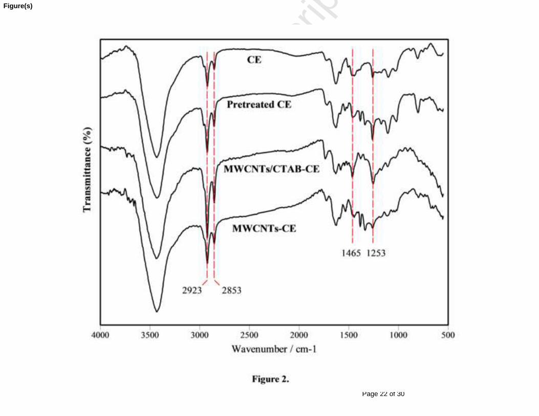
FT-IR spectra of different electrodes are presented in Fig. 2. The addition of cationic
surfactant (CTAB) for charging and dispersing the nanotubes affected the peaks that appeared in
the FT-IR spectra. The broad peak at 3430 cm-1 is attributed to the O–H stretching bond which is
due to the water absorption of the carbon material in the atmosphere. The weak peak observed in
all samples at 1725 cm-1 is related to the C=O bond which is probably due to the impurities of
carbon and MWCNTs. The corresponding peaks of C–H (alkene bending), C=C and C≡C are
placed at 802, 1625 and 2028 cm-1, respectively, which appeared only on CE and Pretreated CE,
meaning that either these bonds do not exist in MWCNTs or they are not numerous. The peaks at
2923 and 2853 cm-1 are related to the symmetric alkane stretching of C–H bond, the intensity of
which is higher in the MWCNTs/CTAB-CE due to the presence of the surfactants. Also the
peaks – appearing at 1465 and 1253 cm-1 attributed to the CH2 (alkane bending) and C–N amine
bond – are exclusively observed in the MWCNTs/CTAB-CE sample due to the existence of the
surfactants.
Figure 2.
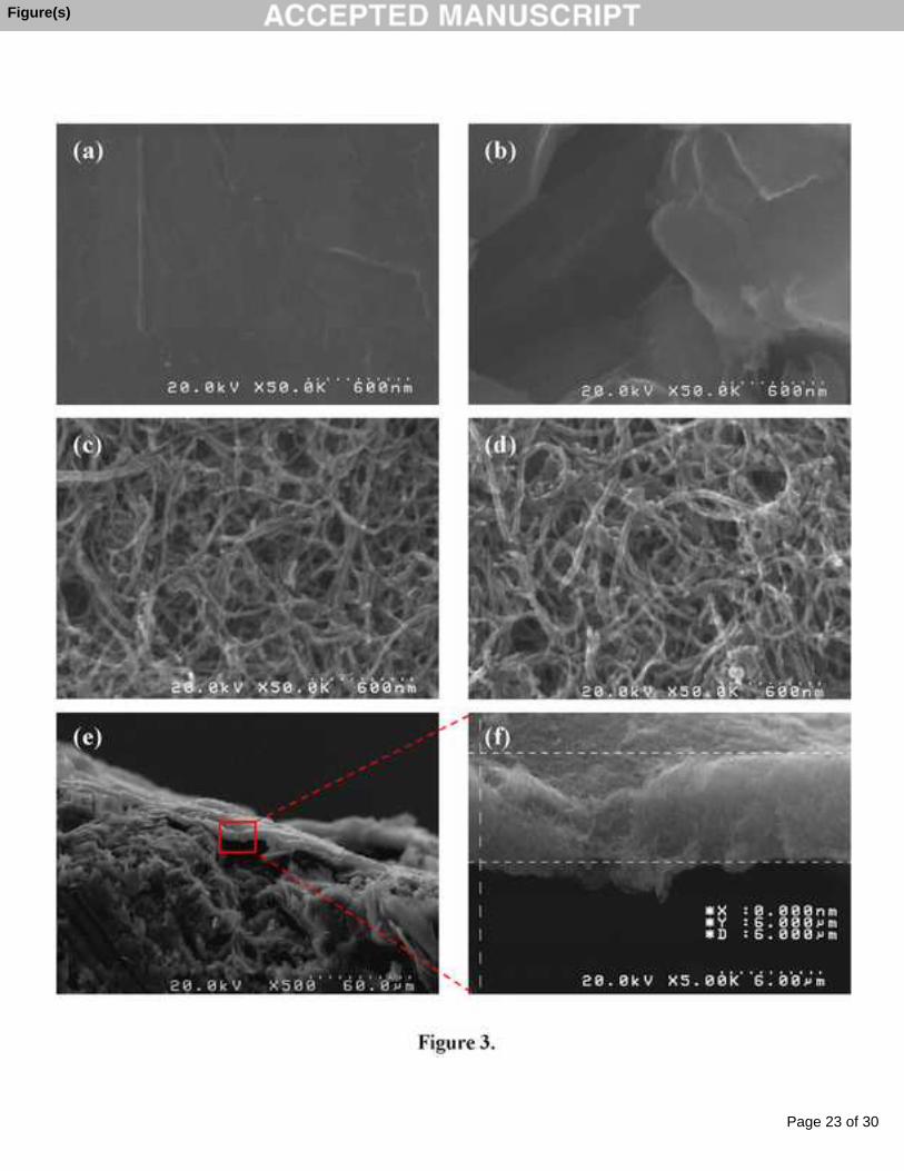
The variation of the surface morphology of CE during the modification process was studied
by FESEM images. The surface of CE before any treatment (Fig. 3(a)) was smooth and even.
Based on the performed experiments, the nanotubes did not deposit on the surface of the
untreated CEs. According to Fig 3(b), the pretreated CE showed a rough and scaly surface
structure which increased the surface area of CE and facilitated the electrodeposition of
nanotubes. Fig 3(c) and (d) illustrated that the nanotubes had been successfully deposited on the
surface of the pretreated electrodes to form a highly porous film, and the subsequent removal of
surfactants from the surface did not affect the nonotubes arrangement on the surface.
Figure 3.
Also the FESEM images of the cross section of modified electrode are shown in Fig. 3(e) and
(f). It can be seen that a thin layer of MWCNTs with the thickness of about 6 μm has been
successfully deposited on the surface of the pretreated CE.
Page 7 of 30
Accep
ted
Man
uscr
ipt
3.2. Electrochemical characterization of the electrodes
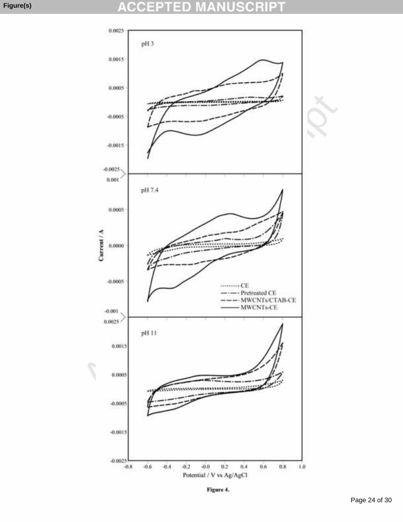
The electrochemical characteristics of the prepared electrodes were investigated by cyclic
voltammetry. Fig. 4 represents the comparative cyclic voltammograms for different CEs
measured in three pH values (3, 7.4 and 11) at a scan rate of 50 mV/s. According to Fig. 4, the
area under the pulse gets larger in the order of: MWCNTs-CE > MWCNTs/CTAB-CE >
Pretreated CE > CE for all pH values, which can be related to the increase of electrochemical
surface area after the pretreatment steps with further electrodeposition of MWCNTs on the
surface; this improves the charge transfer and confirms the formation of a thin layer on the
pretreated CE, which significantly improves its capacitive properties by showing a fairly large
capacitance-like currents. According to the Fig. 4 the CE sample does not show any redox peaks
at all pH values. The Pretreated CE exhibits a weak redox peak at 0.21 V; while, the similar peak
with significantly enhanced current has been observed for MWCNTs-CE sample at pH 7.4. At
pH 3, the redox peaks have been observed at 0.45 and 0.6 V for Pretreated CE and MWCNTs-
CE, respectively, the appearance of which could be related to water discharge. In addition, the
redox peaks observed at the negative potential values for MWCNTs-CE and MWCNTs/CTAB-
CE at pH 7.4 and for MWCNTs-CE at pH 3 are probably attributed to the reduction of the
absorbed oxygen [14, 34]. The results of the redox peaks indicate that these responses are pH
dependent and are due to the redox reaction by the functional groups existing in the
carbonaceous material (as explained earlier in FT-IR analysis) like C=O as impurities. The
obtained results are consonant with the previous studies [35, 36].
Figure 4.
Also Fig. 4 indicates that the pH 3 solution produces the largest area enclosed by the CV
curves and the pseudo-capacitive behaviors are less significant for electrodes in the solution with
higher pH values. Perhaps at lower pH values more hydrogen ions are available as a reagent for
Faradaic reaction [37]. These acquired results are in agreement with previous reports and suggest
that the prepared MWCNTs-CE could be used in energy storage applications in acidic
electrolytes [21].
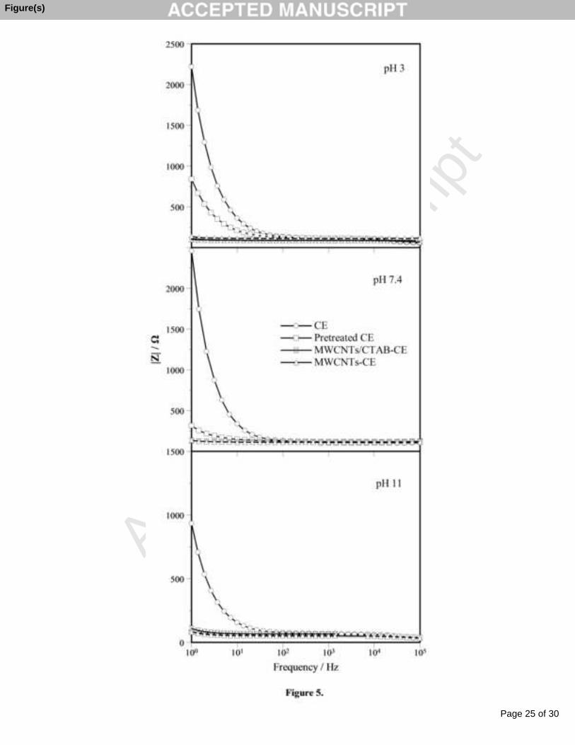
Fig. 5 exhibits the electrochemical impedance of the prepared electrodes. EIS is a sensitive
and non-destructive technique, which is often applied to determine the characterization of
Page 8 of 30
Accep
ted
Man
uscr
ipt
electrode processes and complex interfaces [38]. Therefore, in this research the EIS has been
applied to survey the electrochemical behavior and charge transfer ability across the prepared
electrodes interface.
According to Fig. 5, the electrode impedances at frequencies above 102 Hz do not differ
much and the electrode conductivities are close to each other; this means that the deposition of
nanotubes on the surface of the electrodes does not affect the impedance at high frequencies. But
the impedances of electrodes at low frequencies became distant from each other. For example the
impedance at 1 Hz was reduced up to 95% at both pH 3 and 7.4, and about 91% at pH 11 after
the deposition of nanotubes and further removal of surfactants from the surface, which may be
attributed to the large surface area and high electrical conductivity of the coated nanotubes on the
surface of the electrode lowering the electrode resistance more effectively.
Figure 5.
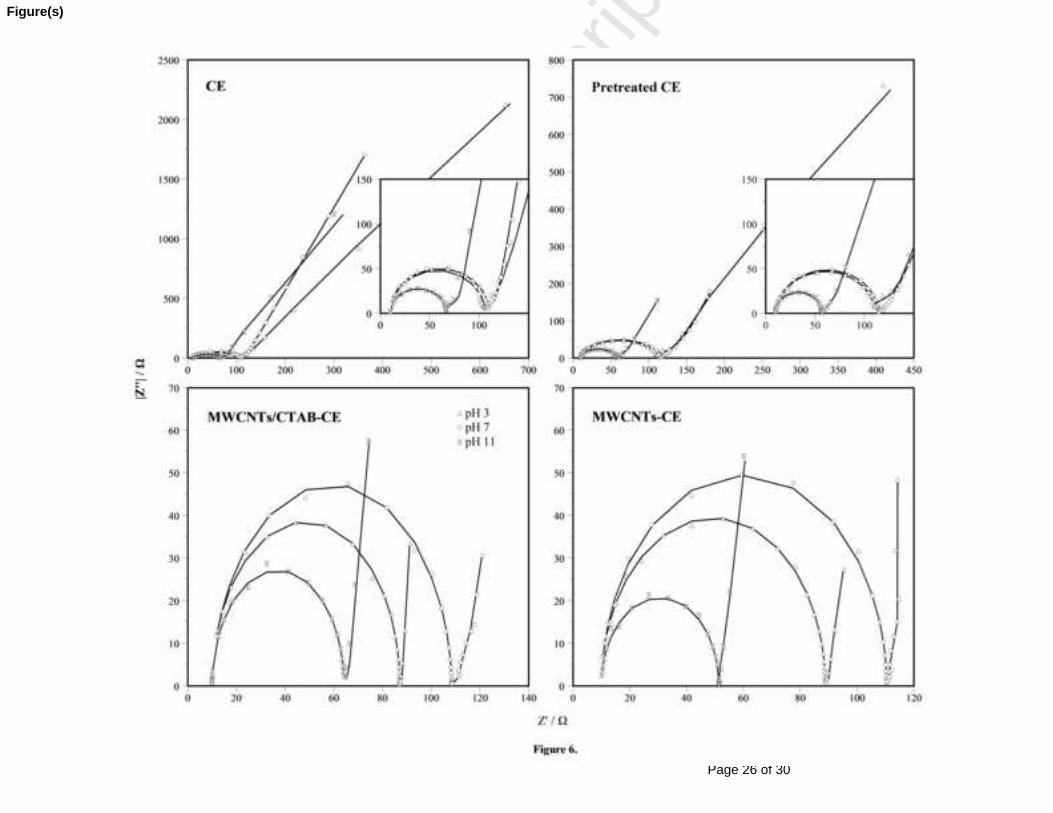
In order to explain the impedance behavior of different electrodes, the proposed equivalent
circuit model estimated from the shape of the data curve in Nyquist plots at pH values of 3, 7.4
and 11 (Fig. 6) was used to fit the EIS measurement results using Zview software.
Figure 6.
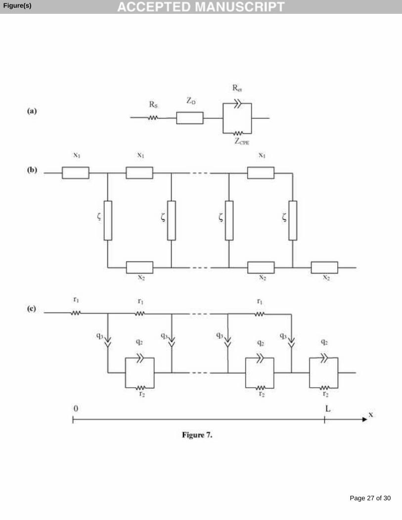
In the present study, the measured data are fitted to the selected circuit to determine the
circuit parameters. According to the circuit model (Fig. 7), Rs is the solution resistance, ZD is the
diffusion impedance and Rct is the charge transfer resistance. ZCPE represents the double layer
constant phase element (CPE), which is explained by equation (2):
(2)
where , ω is the angular frequency (rad/s) = 2πf; f is frequency (Hz). The parameter q
indicates the value of the capacitance of the CPE as n approaches 1. The parameter n (0 < n < 1)
determines the micro fractal and distribution of the phase-phase interface. When n = 0.5 the
impedance equals the Warburg impedance and when n = 1, the CPE is identical to a capacitor
[14, 39].
Page 9 of 30
Accep
ted
Man
uscr
ipt
The semi-circle-like complex plane plots at high frequencies were observed in all electrodes,
while the low frequency line becomes considerably smaller after the pretreatment and deposition
of CNTs on the surface. Since the sloped line similar to Warburg impedance was observed in the
Nyquist plots at low frequencies, the diffusive impedance (Fig. 7) which is generally expressed
with the transmission line model was employed to represent the impedance response of the
diffusion process. This model has been used to analyze different systems where the charge
transfer is controlled by a diffusion mechanism [40-42]. According to Fig. 6 the adoptive model
has shown excellent fitting to the experimental data. In this model ZD is determined using the
following equations (3-5):
(3)
where
(4)
and
(5)
The parameter x1 and x2 refer to the impedance per unit length (Ω/cm) for liquid and solid
phase, respectively, and ζ is the impedance length (Ω.cm) corresponding to the diffusion length L
(cm).
Figure 7.
In the equivalent circuit, the interface and liquid phase is explained by q3 and r1, respectively, and
the solid phase is represented by the parallel connection of r2 and q2.
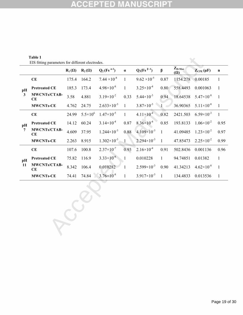
The corresponding fitting data are listed in Table 1. In all samples, L was chosen as 1 and Rs
was 10 Ω. R1 represents the diffusive resistance in the pores of the film, Q3 is related to the
trapping, motion or delay of local charges at the liquid/solid interface; while the combination of
R2 and Q2 are correlated to the disordered solid phase [40, 43]. The obtained results in Table 1
indicate that the resistances in the diffusive model (R1 and R2) decrease after the deposition of
Page 10 of 30
Accep
ted
Man
uscr
ipt
nanotubes on electrode surface for all pH measurements. The reduction of the ion transfer
resistance in pores and interface has significantly decreased the diffusive impedance of the
porous structured MWCNTs -CE and MWCNTs/CTAB-CE. The maximum diffusion impedance
(ZD-Max) obtained at the lowest frequencies (1 Hz) are also given in Table 1. The ZD-Max of the
nanotubes deposited electrodes are 36.90, 47.85 and 134.48 Ω for MWCNTs-CE at pH 3, 7.4 and
11, respectively; which implies the lower energy barrier of charge transfer within the CNTs
deposited films at pH 3 and confirms the data of cyclic voltammetery.
Table 1
Therefore, the equivalent circuit model adopted to explain the shape of the EIS spectra,
suggested that a distributed transfer process was the reason for the disordered line observed at
low frequencies. Also one can conclude that the overall effect of charge transfer in bulk,
electrode/liquid boundaries and the solid phase influence the electrochemical behavior of
electrodes at various range of frequencies in different media.
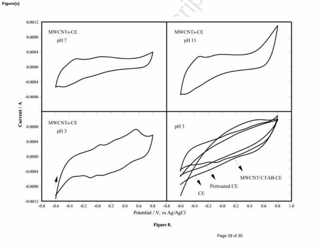
3.3. Determination of MB
The electrochemical response of 3×10⁻² mM MB at the surface of MWCNTs-CE was
investigated in 0.1 mM Fe2(SO4)3 at three pH values (3 for acidic, 7 for neutral and 11 for alkali
media). As it can be seen in Fig. 8, the CE and pretreated CE showed no peak current at pH 3 in
this potential range indicating that there was no redox process on the surface of CE in the
presence of MB. It can be seen that the MWCNTs/CTAB-CE has shown a weak peak at -0.09 V
due to the oxidation of MB at the surface of the electrode. This may be due to the repulsion of
cationic MB and positively charged CTAB on the surface of the electrode, which reduces the
concentration of MB on the surface of the modified electrode. On the other hand, the MWCNTs-
CE has demonstrated different behavior, which means that the nanostructured MWCNTs-CE acts
as an electrocatalyst for the reduction of MB. The huge specific surface area of CNTs can
increase the effective area of the electrode; as a result, the peak current increases too. At pH 11
no peak was observed in the reverse scan suggesting that the oxidation of MB at MWCNTs-CE
Page 11 of 30
Accep
ted
Man
uscr
ipt
is irreversible and weak. Three sets of redox peaks could be discerned at pH 3 and 7. The sharper
and higher current peak at pH 3 suggests that the redox reaction happens faster.
According to the results, the determination of MB and its possible mechanism was
investigated further at pH 3. There are many reports about the reduction of MB in electron
transfer reaction showing one couple redox peaks or two oxidation peaks relating to either
electropolymerization of methylene blue at positive potential or oxidation of MB immobilized on
the surface of the electrode [44-46].
Figure 8.
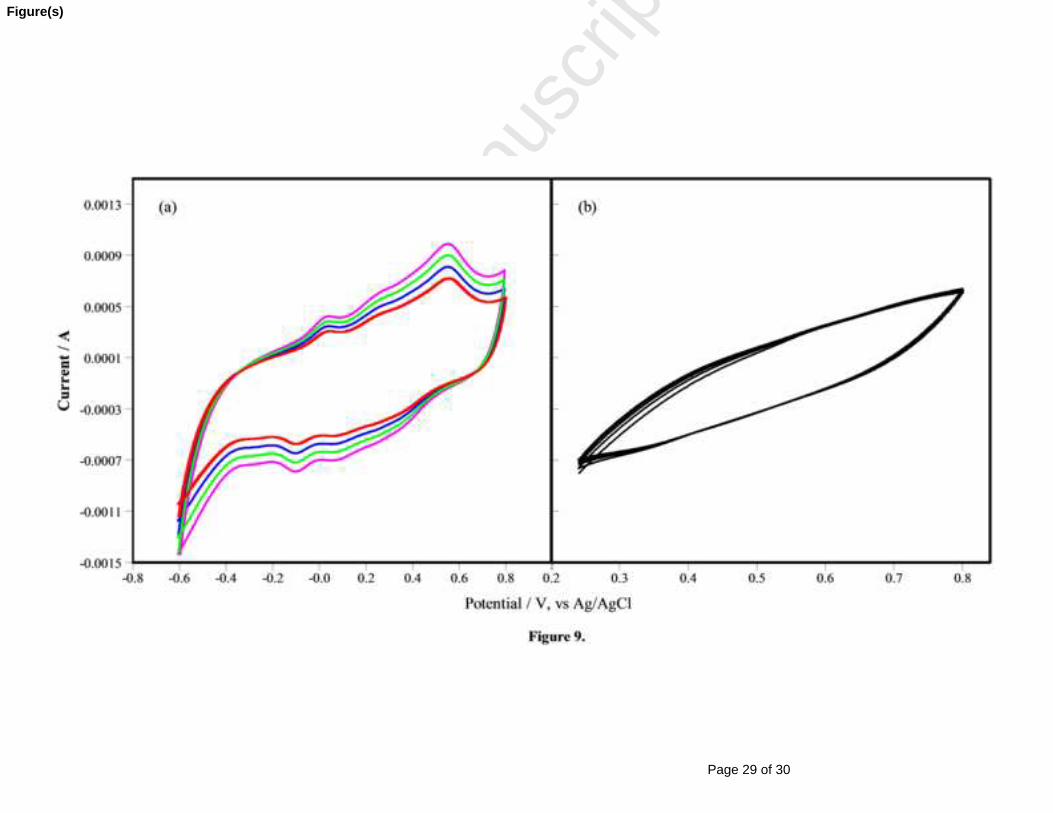
To determine the mechanism of the oxidation of MB at the surface of the MWCNTs-CE, the
cyclic voltammetry were performed 4 times, illustrated in Fig. 9(a). The voltammograms
indicates that the reaction at the surface of the electrode is not the electropolymerization of MB
due to the increasing of the peaks heights by increasing the cycle numbers. If this was an
electropolymerization process, the height of the first peak would decrease; whereas, the height of
the second one (polymer formation) would increase [44, 47].
Fig. 9(b) exhibits the corresponding voltammograms of MB at potential range of 0.25 to 0.8
V for 4 cycles. When the experiment is performed in this potential range, no redox peaks are
observed. This means that the appearance of the second reduction peak is dependent on the
existence of the first, and also the height of the second peak is higher than the first one.
Figure 9.
There are various studies that have investigated the redox mechanism of MB+ in different
media (acidic, neutral and alkali media) on the surface of various electrodes. For example
Bauldreay and Archer reported the oxidation of MB+ on SnO2 electrodes at pH 1 [48], Karyakin
et al. also investigated the oxidation of MB+ at glassy carbon electrodes in aqueous solution at
pH 9.1 [49], Pennarun et al. have discussed the reduction of MB+ at pH 8 at micro-optical ring
electrodes [45], Žutić and Svetliĉić have also studied the reduction of MB+ at gold electrode at
Page 12 of 30
Accep
ted
Man
uscr
ipt
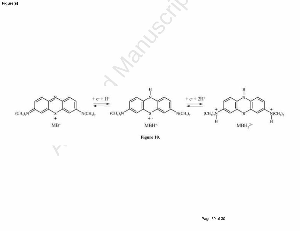
pH 7.9 [50, 51], etc. In the present study, the possible mechanism proposed by the obtained
voltammograms could be described as below:
According to the literatures [46, 52, 53], semi-methylene blue (HMB
+•) could be produced
in acid solution (pH < 6) by taking one electron and one proton, then the unstable semi-
methylene blue takes another electron and forms leucomethylene blue (MBH32+). Then MBH3
2+/
HMB
+• can be oxidized by Fe3+ and form HMB
+•/MB+ and Fe2+. The HMB
+• can also be
reduced by Fe2+ in acidic media to form MBH32+ [52]. The possible reactions of MB+ occurring
at the surface of the MWCNTs-CE can be written as follows (Fig. 10):
Figure 10.
At higher pH values, the formation of insoluble Fe(OH)3 and Fe(OH)2 in the solution could
decrease the redox reactions by Fe3+/Fe2+; and also these iron hydroxides could be polymerized
at pH > 3.5 and there is a possibility that they can remove the dissolved MB+ by surface
complexation or electrostatic attraction that decrease the concentration of MB+ at the surface of
the MWCNTs-CE to lower the current peaks [54].
According to our results, a mechanism for the redox reaction of MB at the surface of the
MWCNTs-CE has been proposed. The work herein did not aim to provide the definite and
detailed mechanism for MB reactions, and our main interest was to compare the voltammograms
resulted from the CE before and after the modification with nanotubes in the presence of MB in
the aqueous media. However, the more precise, comprehensive and quantified survey is needed
to satisfactorily justify the oxidation and reduction mechanism of MB+ at the surface of the
MWCNTs-CE.
4. Conclusion
In this paper the construction and formation of the thin layer deposition of MWCNTs on the
surface of the carbon electrode were performed. Detection of methylene blue as a hazardous
organic compound in aqueous solution was described. The electrodeposition of the MWCNTs
accompanied by cationic surfactants (CTAB) as the driving force toward the cathode has been
demonstrated. The characterization and properties of the electrode through the stages of
preparation have been studied by SEM images, FT-IR spectra and the advancing contact angle.
Page 13 of 30
Accep
ted
Man
uscr
ipt
The obtained data confirmed the structure variation within the modification process; and a
mechanism for the deposition of nanotubes was proposed. The electrochemical impedance
spectroscopy and cyclic voltammetry of CE, pretreated CE, MWCNTs/CTAB-CE and
MWCNTs-CE were also investigated at three pH values (3, 7.4 and 11). The pseudo-capacitive
behavior of the modified electrode was more significant at pH 3. The preparation of MWCNTs-
CE has served two purposes: first to lower the impedance and second, to enlarge the interacting
surface area for the detection of MB. EIS data were fitted with the suggested equivalent circuit,
and the CNTs deposited electrodes showed the lowest diffusive impedance. Due to the unique
electronic structures of theirs, the nanotubes can enhance the electrochemical reaction; therefore,
methylene blue dye was strongly adsorbed on the surface of the electrode and exhibited three
redox peaks. The resulted voltammograms revealed that MB reduces on the surface of
MWCNTs-CE by two electrons in a consecutive two one-electron steps and forming semi-
methylene blue (HMB
+•) and leucomethylene blue (MBH32+). The promising results obtained by
this modified electrode might also be used for the detection of organic and colored hazardous
compounds in different industries as textile industry.
References
[1] B. Baś, A. Bugajna, M. Jakubowska, W. Reczyński, A. Smalec, The renewable glassy
carbon annular band electrode in a highly sensitive normal pulse voltammetric
determination of paracetamol with continuous wavelet transformation, Electrochim. Acta,
99 (2013) 190.
[2] R.A. Davoglio, S.R. Biaggio, N. Bocchi, R.C. Rocha-Filho, Flexible and high surface
area composites of carbon fiber, polypyrrole, and poly(DMcT) for supercapacitor
electrodes, Electrochim. Acta, 93 (2013) 93.
[3] J.G. Kim, J.S. Im, T.-S. Bae, J.H. Kim, Y.-S. Lee, The electrochemical behavior of an
enzyme biosensor electrode using an oxyfluorinated pitch-based carbon, J. Ind. Eng.
Chem., 19 (2013) 94.
[4] F. von Sturm, Carbon Materials. Carbon—Electrochemical and Physicochemical
Properties, Angew. Chem., 100 (1988) 1260.
Page 14 of 30
Accep
ted
Man
uscr
ipt
[5] M.A. El Ries, M.F. Abdel Ghany, L.A. Hussin, F.M. El-Anwar, A.M. Mohamed,
Voltammetric behavior of ketoconazole and its determination in cosmetic preparation
using a β-cyclodextrin modified glassy carbon electrode, Bull. Faculty Pharm., 51 (2013)
49.
[6] Y. Wang, G. Du, L. Zhu, H. Liu, C.-P. Wong, J. Wang, Aligned open-ended carbon
nanotube membranes for direct electrochemistry applications, Sens. Actuators, B, 174
(2012) 570.
[7] M. Coates, T. Nyokong, Characterization of glassy carbon electrodes modified with
carbon nanotubes and iron phthalocyanine through grafting and click chemistry,
Electrochim. Acta, 91 (2013) 158.
[8] J. Simonet, Glassy carbon electrodes doped by surface graphite nano-flakes: Multi-step
redox transitions functionalization, Electrochem. Commun., 30 (2013) 17.
[9] Y. Wang, Y. Wu, J. Xie, X. Hu, Metal–organic framework modified carbon paste
electrode for lead sensor, Sens. Actuators, B, 177 (2013) 1161.
[10] P. Raghu, T. Madhusudana Reddy, K. Reddaiah, L.R. Jaidev, G. Narasimha, A novel
electrochemical biosensor based on horseradish peroxidase immobilized on Ag-
nanoparticles/poly(l-arginine) modified carbon paste electrode toward the determination
of pyrogallol/hydroquinone, Enzyme Microb. Technol., 52 (2013) 377.
[11] A. Trych, Further Study of Carbon Fibres Electrodes in Micro Electrical Discharge
Machining, Procedia CIRP, 6 (2013) 310.
[12] W. Geremedhin, M. Amare, S. Admassie, Electrochemically pretreated glassy carbon
electrode for electrochemical detection of fenitrothion in tap water and human urine,
Electrochim. Acta, 87 (2013) 749.
[13] K. Tyszczuk-Rotko, R. Metelka, K. Vytřas, Screen-printed carbon electrodes modified
with lead film deposited using different plating methods as sensors in anodic stripping
voltammetry, Electrochim. Acta, 92 (2013) 335.
[14] H. Zhou, T. Wang, Y.Y. Duan, A simple method for amino-functionalization of carbon
nanotubes and electrodeposition to modify neural microelectrodes, J. Electroanal. Chem.,
688 (2013) 69.
Page 15 of 30
Accep
ted
Man
uscr
ipt
[15] F. Fathirad, D. Afzali, A. Mostafavi, T. Shamspur, S. Fozooni, Fabrication of a new
carbon paste electrode modified with multi-walled carbon nanotube for stripping
voltammetric determination of bismuth (III), Electrochim. Acta, 103 (2013) 206.
[16] B. Dogan-Topal, B. Bozal-Palabıyık, B. Uslu, S.A. Ozkan, Multi-walled carbon
nanotube modified glassy carbon electrode as a voltammetric nanosensor for the sensitive
determination of anti-viral drug valganciclovir in pharmaceuticals, Sens. Actuators, B,
177 (2013) 841.
[17] S.-P. Zhang, Y. Zheng, L.-G. Shan, L.-y. Shi, K.-l. Leng, Complex and new
modification techniques of thiocholine detection electrodes with carbon nanotubes, Appl.
Surf. Sci., 255 (2008) 439.
[18] S. Shahrokhian, M. Ghalkhani, M. Adeli, M.K. Amini, Multi-walled carbon nanotubes
with immobilised cobalt nanoparticle for modification of glassy carbon electrode:
Application to sensitive voltammetric determination of thioridazine, Biosens.
Bioelectron., 24 (2009) 3235.
[19] S. Laschi, E. Bulukin, I. Palchetti, C. Cristea, M. Mascini, Disposable electrodes
modified with multi-wall carbon nanotubes for biosensor applications, IRBM Ing. Rech.
Biomed., 29 (2008) 202.
[20] E. Baldrich, R. Gómez, G. Gabriel, F.X. Muñoz, Magnetic entrapment for fast, simple
and reversible electrode modification with carbon nanotubes: Application to dopamine
detection, Biosens. Bioelectron., 26 (2011) 1876.
[21] J. Kang, J. Wen, S.H. Jayaram, X. Wang, S.-K. Chen, Electrochemical characterization
and equivalent circuit modeling of single-walled carbon nanotube (SWCNT) coated
electrodes, J. Power Sources, 234 (2013) 208.
[22] W. Lee, V. Parpura, Carbon nanotubes as substrates/scaffolds for neural cell growth, in:
S.H. Shanker (Ed.), Progress in Brain Research, Vol. 180, Ch. 6, Elsevier, 2009, p. 110.
[23] C. Klumpp, K. Kostarelos, M. Prato, A. Bianco, Functionalized carbon nanotubes as
emerging nanovectors for the delivery of therapeutics, Biochim. Biophys. Acta, 1758
(2006) 404.
[24] X. Duan, F. Ma, Z. Yuan, L. Chang, X. Jin, Comparative studies on the electro-
catalytic oxidation performance of surfactant–carbon nanotube-modified PbO2 electrodes,
J. Electroanal. Chem., 677–680 (2012) 90.
Page 16 of 30
Accep
ted
Man
uscr
ipt
[25] M.H. van der Veen, B. Vereecke, C. Huyghebaert, D.J. Cott, M. Sugiura, Y. Kashiwagi,
L. Teugels, R. Caluwaerts, N. Chiodarelli, P.M. Vereecken, G.P. Beyer, M.M. Heyns, S.
De Gendt, Z. Tökei, Electrical characterization of CNT contacts with Cu Damascene top
contact, Microelectron. Eng., 106 (2013) 106.
[26] A. Kumaravel, M. Chandrasekaran, Nanosilver/surfactant modified glassy carbon
electrode for the sensing of thiamethoxam, Sens. Actuators, B, 174 (2012) 380.
[27] M. Noroozifar, M. Khorasani-Motlagh, A. Taheri, Determination of cyanide in
wastewaters using modified glassy carbon electrode with immobilized silver
hexacyanoferrate nanoparticles on multiwall carbon nanotube, J. Hazard. Mater., 185
(2011) 255.
[28] L. Vaisman, H.D. Wagner, G. Marom, The role of surfactants in dispersion of carbon
nanotubes, Adv. Colloid Interface Sci., 128–130 (2006) 37.
[29] S. Swarup, C.K. Schoff, A survey of surfactants in coatings technology, Prog. Org. Coat.,
23 (1993) 1.
[30] M.Y. Pletnev, Chemistry of surfactants, in: V.B. Fainerman, D. Möbius, R. Miller (Eds.),
Studies in Interface Science, Vol. 13, Elsevier, 2001, p. 1.
[31] A.S.N. Murthy, K.S. Reddy, Cyclic voltammetric studies of methylene blue in presence
of Fe3+: catalytic currents, Electrochim. Acta, 28 (1983) 1677.
[32] A.I. Rusanov, A.K. Shchekin, D.V. Tatyanenko, The line tension and the generalized
Young equation: the choice of dividing surface, Colloids Surf., A, 250 (2004) 263.
[33] D.Y. Kwok, A.W. Neumann, Contact angle interpretation in terms of solid surface
tension, Colloids Surf., A, 161 (2000) 31.
[34] K. Wang, H.A. Fishman, H. Dai, J.S. Harris, Neural Stimulation with a Carbon
Nanotube Microelectrode Array, Nano Lett., 6 (2006) 2043.
[35] G. Che, B.B. Lakshmi, E.R. Fisher, C.R. Martin, Carbon nanotubule membranes for
electrochemical energy storage and production, Nature, 393 (1998) 346.
[36] A.G. Rinzler, et al., Large-scale purification of single-wall carbon nanotubes: process,
product, and characterization, Appl. Phys. A, 67 (1998) 29.
[37] H. Farsi, F. Gobal, H. Raissi, S. Moghiminia, The pH effects on the capacitive behavior
of nanostructured molybdenum oxide, J. Solid State Electrochem., 14 (2010) 681.
Page 17 of 30
Accep
ted
Man
uscr
ipt
[38] J. Bisquert, G. Garcia-Belmonte, F. Fabregat-Santiago, N.S. Ferriols, P. Bogdanoff,
E.C. Pereira, Doubling exponent models for the analysis of porous film electrodes by
impedance. relaxation of TiO2 nanoporous in aqueous solution, J. Phys. Chem. B, 104
(2000) 2287.
[39] Y.Y. Duan, G.M. Clark, R.S.C. Cowan, A study of intra-cochlear electrodes and tissue
interface by electrochemical impedance methods in vivo, Biomaterials, 25 (2004) 3813.
[40] J. Bisquert, A. Compte, Theory of the electrochemical impedance of anomalous
diffusion, J. Electroanal. Chem., 499 (2001) 112.
[41] G. Garcia-Belmonte, Z. Pomerantz, J. Bisquert, J.-P. Lellouche, A. Zaban, Analysis of
ion diffusion and charging in electronically conducting polydicarbazole films by
impedance methods, Electrochim. Acta, 49 (2004) 3413.
[42] J. Bisquert, G. Garcia-Belmonte, F. Fabregat-Santiago, P.R. Bueno, Theoretical models
for ac impedance of finite diffusion layers exhibiting low frequency dispersion, J.
Electroanal. Chem., 475 (1999) 152.
[43] J. Bisquert, V.S. Vikhrenko, Analysis of the kinetics of ion intercalation. Two state
model describing the coupling of solid state ion diffusion and ion binding processes,
Electrochim. Acta, 47 (2002) 3977.
[44] H. Farsi, S. Hosseini, The electrochemical behaviors of methylene blue on the surface of
nanostructured NiWO4 prepared by coprecipitation method, J. Solid State Electrochem.,
17 (2013) 2079.
[45] G.I. Pennarun, C. Boxall, D. O'Hare, Micro-optical ring electrode: development of a
novel electrode for photoelectrochemistry, Analyst, 121 (1996) 1779.
[46] N. Leventis, M. Chen, Electrochemically assisted sol−gel process for the synthesis of
polysiloxane films incorporating phenothiazine dyes analogous to methylene blue:
Structure and ion-transport properties of the films via spectroscopic and electrochemical
characterization, Chem. Mater., 9 (1997) 2621.
[47] H. Ju, J. Zhou, C. Cai, H. Chen, The electrochemical behavior of methylene blue at a
microcylinder carbon fiber electrode, Electroanalysis, 7 (1995) 1165.
[48] J.M. Bauldreay, M.D. Archer, Dye-modified electrodes for photogalvanic cells,
Electrochim. Acta, 28 (1983) 1515.
Page 18 of 30
Accep
ted
Man
uscr
ipt
[49] A.A. Karyakin, A.K. Strakhova, E.E. Karyakina, S.D. Varfolomeyev, A.K.
Yatsimirsky, The electrochemical polymerization of methylene blue and
bioelectrochemical activity of the resulting film, Bioelectrochem. Bioenerg., 32 (1993)
35.
[50] V. Žutić, V. Svetličić, J. Clavilier, J. Chevalet, Supramolecular phenomena in organic
redox films at electrodes: Part II. The methylene blue/leucomethylene blue redox couple
at the gold electrode, J. Electroanal. Chem. Interfacial Electrochem., 219 (1987) 183.
[51] V. Svetličić, V. Žutić, J. Clavilier, J. Chevalet, Organic monolayer formation at a
sulphur modified gold electrode: The methylene blue/leucomethylene blue redox couple,
J. Electroanal. Chem. Interfacial Electrochem., 233 (1987) 199.
[52] D.W. Hay, S.A. Martin, S. Ray, N.N. Lichtin, Disproportionation of semimethylene
blue and oxidation of leucomethylene blue by methylene blue and by Fe(III). Kinetics,
equilibria, and medium effects, J. Phys. Chem., 85:11 (1981) 1474.
[53] P.D. Wildes, N.N. Lichtin, M.Z. Hoffman, L. Andrews, H. Linschitz, Anion and
solvent effects on the rate of reduction of triplet excited thiazine dyes by ferrous ions,
Photochem. Photobiol., 25 (1977) 21.
[54] C.A. Martínez-Huitle, E. Brillas, Decontamination of wastewaters containing synthetic
organic dyes by electrochemical methods: A general review, Appl. Catal., B, 87 (2009)
105.
Page 19 of 30
Accep
ted
Man
uscr
ipt
Table 1 EIS fitting parameters for different electrodes.
R1 (Ω) R2 (Ω) Q2 (Fs α-1) α Q3(Fs β -1) β ZD-Max (Ω) ZCPE (μF) n
CE 175.4 164.2 7.44 ×10⁻⁸ 1 9.62 ×10⁻⁵ 0.87 1154.278 0.00185 1
Pretreated CE 185.3 173.4 4.98×10⁻⁸ 1 3.25×10⁻⁴ 0.80 558.4493 0.001063 1 MWCNTs/CTAB-CE 3.58 4.881 3.19×10⁻² 0.33 5.44×10⁻³ 0.94 18.64538 5.47×10⁻⁸ 1
pH 3
MWCNTs-CE 4.762 24.75 2.633×10⁻³ 1 3.87×10⁻³ 1 36.90365 5.11×10⁻⁸ 1
CE 24.99 5.5×10⁶ 1.47×10⁻⁵ 1 4.11×10⁻⁴ 0.82 2421.503 6.59×10⁻³ 1
Pretreated CE 14.12 60.24 3.14×10⁻⁴ 0.87 8.36×10⁻⁴ 0.85 193.8133 1.06×10⁻² 0.95 MWCNTs/CTAB-CE 4.609 37.95 1.244×10⁻³ 0.88 4.109×10⁻³ 1 41.09485 1.23×10⁻² 0.97
pH 7
MWCNTs-CE 2.263 8.915 1.302×10⁻³ 1 2.294×10⁻³ 1 47.85473 2.25×10⁻² 0.99
CE 107.6 100.8 2.37×10⁻⁷ 0.93 2.16×10⁻⁴ 0.91 502.8436 0.001136 0.96
Pretreated CE 75.82 116.9 3.33×10⁻⁸ 1 0.010228 1 94.74851 0.01382 1 MWCNTs/CTAB-CE 8.342 106.4 0.010282 1 2.599×10⁻³ 0.90 41.34213 4.62×10⁻⁸ 1
pH 11
MWCNTs-CE 74.41 74.84 3.76×10⁻⁸ 1 3.917×10⁻³ 1 134.4833 0.013536 1
Page 20 of 30
Accep
ted
Man
uscr
ipt
Figure Captions:
Fig. 1. Schematic of the proposed modification steps.
Fig. 2. FT-IR spectra of CE, Pretreated CE, MWCNTs/CTAB-CE and MWCNTs-CE.
Fig. 3. FESEM images of the surface of (a): CE, (b): Pretreated CE, (c): MWCNTs/CTAB-CE
and (d): MWCNTs-CE and the cross section of MWCNTs-CE: (e) and (f).
Fig. 4. Cyclic voltammograms of different CEs at pH 3, 7.4 and 11 at a scan rate of 50 mV/s.
Fig. 5. Bode modulus plots of electrochemical impedance for different CEs at pH 3, 7.4 and 11.
Fig. 6. Nyquist plots of electrochemical impedance for different CEs at pH 3, 7.4 and 11, the
fitting results are shown with the solid line.
Fig. 7. Adoptive equivalent circuit model for electrodes.
Fig. 8. Cyclic voltammograms of 3×10⁻² mM MB at different pH values in 0.1 mM Fe2(SO4)3
and scan rate of 50 mV/s.
Fig. 9. Four cyclic voltammograms of 3×10⁻² mM MB at pH 3 in 0.1 mM Fe2(SO4)3 at scan rate
of 50 mV/s.
Fig. 10. Mechanism of MB reduction.
Page 21 of 30
Accep
ted
Man
uscr
ipt
Figure(s)
Page 22 of 30
Accep
ted
Man
uscr
ipt
Figure(s)
Page 23 of 30
Accep
ted
Man
uscr
ipt
Figure(s)
Page 24 of 30
Accep
ted
Man
uscr
ipt
Figure(s)
Page 25 of 30
Accep
ted
Man
uscr
ipt
Figure(s)
Page 26 of 30
Accep
ted
Man
uscr
ipt
Figure(s)
Page 27 of 30
Accep
ted
Man
uscr
ipt
Figure(s)
Page 28 of 30
Accep
ted
Man
uscr
ipt
Figure(s)
Page 29 of 30
Accep
ted
Man
uscr
ipt
Figure(s)
Page 30 of 30
Accep
ted
Man
uscr
ipt
Figure(s)