STRATEGIC/TACTICAL OPTICAL DISK SYSTEM (S/TODS ... · rewritable optical disk media, (b) rugged...
31
AFRL-IF-RS-TR-1999-21 Final Technical Report February 1999 STRATEGIC/TACTICAL OPTICAL DISK SYSTEM (S/TODS), DEPLOYABLE OPTICAL JUKEBOX EVALUATION L-3 Communications Corporation Taras Kozak and William Vaughan APPROVED FOR PUBLIC RELEASE; DISTRIBUTION UNLIMITED. AIR FORCE RESEARCH LABORATORY INFORMATION DIRECTORATE ROME RESEARCH SITE ROME, NEW YORK BEC QUAX1T7 DISSECTED 4
Transcript of STRATEGIC/TACTICAL OPTICAL DISK SYSTEM (S/TODS ... · rewritable optical disk media, (b) rugged...

AFRL-IF-RS-TR-1999-21 Final Technical Report February 1999
STRATEGIC/TACTICAL OPTICAL DISK SYSTEM (S/TODS), DEPLOYABLE OPTICAL JUKEBOX EVALUATION
L-3 Communications Corporation
Taras Kozak and William Vaughan
APPROVED FOR PUBLIC RELEASE; DISTRIBUTION UNLIMITED.
AIR FORCE RESEARCH LABORATORY INFORMATION DIRECTORATE
ROME RESEARCH SITE ROME, NEW YORK
BEC QUAX1T7 DISSECTED 4

This report has been reviewed by the Air Force Research Laboratory, Information Directorate, Public Affairs Office (IFOIPA) and is releasable to the National Technical Information Service (NTIS). At NTIS if will be releasable to the general public, including foreign nations.
AFRL-IF-RS-TR-1999-21 has been reviewed and is approved for publication.
tfuji 7/< iläkM*u APPROVED: FREDN.HARITATOS Project Engineer
FOR THE DIRECTOR: JOSEPH CAMERA, Deputy Chief Information & Intelligence Exploitation Division Information Directorate
If your address has changed or if you wish to be removed from the Air Force Research Laboratory Rome Research Site mailing list, or if the addressee is no longer employed by your organization, please notify AFRL/IFED, 32 Brooks Road, Rome, NY 13441-4114. This will assist us in maintaining a current mailing list.
Do not return copies of this report unless contractual obligations or notices on a specific document require that it be returned.

STRATEGIC/TACTICAL OPTICAL DISK SYSTEM (S/TODS), DEPLOYABLE OPTICAL JUKEBOX EVALUATION
Taras Kozak and William Vaughan
This report is a companion to:
RL-TR-97-96, Vol I, Jul 97, STRATEGIC/TACTICAL OPTICAL DISK SYSTEM S/TODS JUKEBOX
RL-TR-97-96, Vol II, Jul 97, STRATEGIC/TACTICAL OPTICAL DISK SYSTEM S/TODS AIRBORNE RECORDER

REPORT DOCUMENTATION PAGE Form Approved
OMB No. 0704-0188
Public reporting burden lor thit co«Kl»n of inform.tion it estimated to average I hour perresponse, including the «me lor rcvfewng instructions, searching .listing datosources, getheringanI maintain^| thedan needed, aruf on^ruj andremw ng the collection Si information. Sand comments rogarding this burden estimate or any other aspect of this collection of information, including suggestions for reducing th»bwdejto' ««"mpton Headquarters Same«. Dnctorate for Information Operations and Reports 1215 Jefferson Davis Highway, Suite 1204, Arlington, VA 222024302, and to the Office of Management and Budget, Paperwork Reduction Project (070*0188), Washington, DC 20503.
1. AGENCY USE ONLY (Leave blank) 2. REPORT DATE
February 1999
3. REPORT TYPE AND DATES COVERED
Final Apr 96 - Sep 98 4. TITLE AND SUBTITLE
STRATEGIC/TACTICAL OPTICAL DISK SYSTEM (S/TODS), DEPLOYABLE OPTICAL JUKEBOX EVALUATION
6. AUTH0RIS)
Taras Kozak and William Vaughan
7. PERFORMING ORGANIZATION NAME(S) AND ADDRESS(ES)
L-3 Communications Corporation Communications Systems East Division 1 Federal Street CarnHen NT 08102
SPONSORING/MONITORING AGENCY NAME(S) AND ADDRESSIES)
Air Force Research Laboratory/IFED 32 Brooks Road Rome NY 13441-4114
5. FUNDING NUMBERS
C - F30602-96-C-O052 PE - 63726F PR - 3192 TA - OO WU - 11
I. PERFORMING ORGANIZATION REPORT NUMBER
N/A
10. SPONSORING/MONITORING AGENCY REPORT NUMBER
AFRL-IF-RS-TR-1999-21
11. SUPPLEMENTARY NOTES
Air Force Research Laboratory Project Engineer: Fred N. Haritatos/IFED/(315) 330-1638
12a. DISTRIBUTION AVAILABILITY STATEMENT
Approved for public release; distribution unlimited.
12b. DISTRIBUTION CODE
13. ABSTRACT (Maximum 200 words!
The purpose of this effort is to demonstrate, test and evaluate new optical disk storage technology. An Advanced Development Model (ADM) was developed which consisted of the following subsystems: (a) ten (10), large format, rewritable optical disk media, (b) rugged optical disk drive for data recording, read-out and erasure, and (c) a robotic access mechanism for automated disk movement under computer control. The jukebox device was designed for worldwide deployments and quick assembly with minimal tools or experience. Under this effort, the storage device was demonstrated within several Air Force facilities to include: Air Force Research Laboratory (AFRL), Electronics System Center (ESC), Air Intelligence Agency (AIA), and Air Force Special Operations Command (AFSOC). Equipment demonstrations were conducted at these locations to seek user feedback needed to refine the system concept of operations and begin the transition
phase.
This technical report is a companion to:
RL-TR-97-96, Vol I, Jul 97, STRATEGIC/TACTICAL OPTICAL DISK SYSTEM S/TODS JUKEBOX RL-TR-97-96, Vol II, Jul 97, STRATEGIC/TACTICAL OPTICAL DISK SYSTEM S/TODS AIRBORNE RECORDER
14. SUBJECT TERMS
Optical Disk, Robotic Mechanism, Jukebox, Storage and Retrieval
17. SECURITY CLASSIFICATION OF REPORT
UNCLASSIFIED
18. SECURITY CLASSIFICATION OF THIS PAGE
UNCLASSIFIED
19. SECURITY CLASSIFICATION OF ABSTRACT
UNCLASSIFIED
15. NUMBER OF PAGES
36 16. PRICE CODE
20. LIMITATION OF ABSTRACT
. UL Standard Form 298 (Rev. 2-89) (EG) Prescribed by ANSI Std. 238.18 . Designed using Perform Pro. WHSIDIOH, Oct M

TABLE OF CONTENTS
SECTION 1 INTRODUCTION 1
1.1 SUMMARY 1
1.2 SCOPE 1
1.3 PROGRAM OVERVIEW 2
1.3.1 Airborne Phase 2 1.3.2 JukeboxPhase 2
1.3.3 Demonstration / Evaluation / COTS Transition Phase 2 1.4 GENERAL DESCRIPTION OF THE EQUIPMENT 3 1.4.1 General Performance Specifications 3 1.4.2 The S/TODS Jukebox Equipment 4
1.4.3 The Optical DiskDrive Equipment • 4
1.4.3.1 Modifications for Jukebox Operation 5 1.4.4 Media 5
1.5 HOST INTEGRATION 5
1.5.1 SCSI 2 Interface 5
1.5.2 Sun Workstation 5
1.5.3 Air Force Mission Planning Systems 5
1.5.4 Metior HSM 6
SECTION 2 JUKEBOX ANALYSIS 7
2.1 INTRODUCTION 7
2.2 SIZE 7
2.2.1 Volume 7
2.2.2 Weight ■ 7
2.2.3 Deployment 7
2.3 ENVIRONMENT 8
2.3.1 Transport 8
2.3.2 Operational 8
2.3.2.1 Cooling 8
2.4 INTERFACE 8
2.4.1 Control and Data Interface 9 2.4.2 Operator Interface 9 2.4.3 Power Input 9 2.5 CYCLE TIME 9
2.5.1 Dual Picker Mechanism 9 2.5.2 Rotation and Translation Stepper Motors 9 2.6 JUKEBOX SYSTEM CONTROL 10 2.6.1 Mechanism Control Electronics 1° 2.6.1.1 DAM Controller Nest 10
2.6.1.2 Rotation and Translation Motors and Indexers 10 2.6.2 Safety 1° 2.6.2.1 Sensors 1° 2.6.2.2 Firmware Abort Scenarios H 2.6.3 Self Test H 2.7 CAPACITY n
SECTION 3 DEMONSTRATIONS OF S/TODS JUKEBOX 12
3.1 S/TODS JUKEBOX DEMONSTRATION SITES 12
TABLE OF CONTENTS
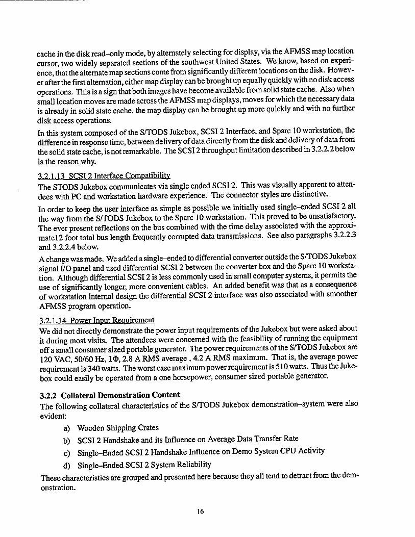
3.1.1 Summary of sites 12 3.1.2 Reason these Sites were Chosen 12 3.2 DEMONSTRATION CONTENT 12 3.2.1 Primary Demonstration Content 12 3.2.1.1 Field Transportability 13
3.2.1.2 Setup Time 13
3.2.1.3 Storage Capacity 13
3.2.1.4 Potential for Capacity Expansion 14 3.2.1.5 Data Access Time including Media Moves 14 3.2.1.6 Average Data Transfer Rate (Throughput) 14 3.2.1.7 Remote / Automatic Selection of Media 14 3.2.1.8 Convenience of Changing Disk Cache Contents 15 3.2.1.9 Convenience of Swapping Entire Disk Cache 15 3.2.1.10 Data Security Issues i5
3.2.1.11 Self Test and Diagnostics I5
3.2.1.12 Integrated 3 Track Capacity Solid State Data Cache 15 3.2.1.13 SCSI 2 Interface Compatibility 16 3.2.1.14 Power Input Requirement 16 3.2.2 Collateral Demonstration Content 16 3.2.2.1 Wooden Shipping Crates I7
3.2.2.2 SCSI 2 Handshake and its Influence on Average Data Transfer Rate .. 17 3.2.2.3 Single-Ended SCSI 2 Handshake and Demo System CPU Activity.... 17 3.2.2.4 Single-Ended SCSI 2 System Reliability 17 3.3 DISCUSSIONS WITH DEMONSTRATION ATTENDEES 18 3.3.1 Compilation of Responses from Demo Attendees 18 3.3.2 The Battle Field Data Storage "Ground Truth" 19 3.3.3 Some Potential Applications for the S/TODS Jukebox System 19 3.3.3.1 AFSOC Mission Planner I9
3.3.3.2 Theater Missile Defense 20 3.3.3.3 Force Protection Planning 21 3.3.3.4 Soldier's Medical Records 21
SECTION 4 TRANSITION to "COTS" DRIVE & MEDIA 23
4.1 RECENT S/TODS JUKEBOX DEVELOPMENT PLAN 23 4.1.1 Summary of the Recent Plan 23 4.1.2 Shortcomings of Existing S/TODS 23 4.1.2.1 Availability of Recording Media 23 4.1.2.2 Availability of Disk Drive 23 4.1.3 Advantages of More COTS Hardware 23 4.1.3.1 Availability of Recording Media 23 4.1.3.2 Availability of Disk Drive 23 4.1.3.3 Expected Synergy due to Kodak Commercial Target Markets 24 4.1.3.4 Advantages of L-3 / Kodak S/TODS Hybrid 24 4.2 THE COTS REALITY 24 4.2.1 Migration of Key Personnel 24 4.2.2 Change in Kodak Commercial Business Strategy 24 4.3 SflODS JUKEBOX PROGRAM STATUS SUMMARY 24
11

SECTION 1
INTRODUCTION
1.1 SUMMARY
This volume describes the results of the field demonstrations of the Strategic / Tactical Optical Disk System Jukebox (S/TODS Jukebox) by L-3 Communications Corp., Communications Systems East Div., for the United States Air Force, Air Force Research Laboratory, Information Directorate, In- formation and Intelligence Exploitation Division, under Contract No: F30602-96-C-0052. The purpose of this contract was to demonstrate and evaluate deployable optical jukebox system that can meet the U.S. Air Force's current and future mass storage requirements. That is, the purpose of this contract was to demonstrate, test, and evaluate a 10 disk ruggedized deployable Jukebox based on the S/TODS Airborne Optical Disk Recorder and Media previously developed under Phases 1 and 2 of contract F30602-89-C-008. An additional purpose of this contract was to begin a transition to greater use of commercial off the shelf hardware within the S/TODS Jukebox system. The single disk S/TODS Advanced Development Model (ADM) Airborne Recorder and the Media development (Phase 1) is covered in Volume 1 of this report. The equipment developed in Phase 1 was utilized in Phase 2. The modifications required to convert the Airborne disk drive for installa- tion in a 10 disk Jukebox (Phase 2) are covered in volume 2 of this report. The demonstrations to potential users at Air Force sites of the completed S/TODS Jukebox are covered in this volume. The Jukebox incorporates features such as a rugged, modular design for quick easy deployment set- up and tear down, dual picker robotics for fast cycle time, and an easily interchangeable disk cache for rapid data access in very large capacity applications. System capacity is 120 GBytes per 10 disk cache. Control and data interface is standard SCSI 2. The S/TODS Jukebox was demonstrated to Air Force personnel at the following four sites:
1 Air Force Special Operations Command, Hurlburt Field, Florida 1-15-95
2 Air Force Research Laboratories, Rome, New York 11-14-96
3 CUBE, Hanscom Air Force Base, Massachusetts 11-6-97 4 Air Force Intelligence Agency, Kelly Air Force Base, Texas 1-27-98
The Jukebox was demonstrated and tested serving as a very large capacity, standard SCSI peripheral to a Sun Sparc 10 workstation running the Air Force Mission Support System (AFMSS). The demonstration at the Air Force's Special Operations Command (AFSOC) was a special case. There the workstation was setup to run the Special Operations Forces Planning and Rehearsal (SOF- PARS) mission planner. The workstation was also loaded with Hierarchical Storage Management (HSM) software which when integrated with the mission planner and the S/TODS Jukebox, pro- vides automatic, transparent management of the 10 disk cache. That is, the HSM makes the S/TODS Jukebox look, to the computer system user, like a 120GByte hard drive.
1.2 SCOPE
This volume covers both a portion of the analysis and design used in the development of the S/TODS Jukebox and it covers the findings from the field demonstrations.

1.3 PROGRAM OVERVIEW
This program was performed in three consecutive phases. Phase 1, covered in Volume 1 of this re- port, developed the airborne single disk S/TODS Advanced Development Model (S/TODS ADM) and the custom 14" media. Phase 2, covered in Volume 2 of this report, developed a 10 disk deploy- able Jukebox based on the recorder and media from the previous phase. The airborne recorder devel- opment built on the results of the Durable I and Durable II optical disk programs (see RADC- TR-86-82 and RADC-TR-88-209), where key risk areas were evaluated and system trade-off studies were performed. In Phase 3 the S/TODS Jukebox was shipped to an appropriate group of Air Force sites for demonstration and to elicit feedback from potential users. This phase also pro- vided ground work for transition to incorporation of a greater amount of commercial off the shelf (COTS ) hardware into the S/TODS Jukebox program.
13.1 Airborne Phase A high performance optical disk recorder for use in Scientific and Technical (S&T) Aircraft was designed, built and tested in Phase 1 of this program. Custom, 14 inch diameter, rewritable magne- to-optic media was developed under subcontract by 3M. Analysis and design began in December, 1988. The recorder demonstrated successful operation under stressful conditions during September 1993 flight tests on an RC-135 aircraft. The disk drive operated without error through aircraft ma- neuvers including 60 degree bank rums, takeoff and landings, and tactical descents. Acceptance test was completed in February 1994. Volume 1 of this report covers all these efforts in detail.
1.3.2 Jukebox Phase Following the Airborne phase, a 10 disk Jukebox version of the S/TODS recorder was designed, built, and tested. Design was begun in September 1993, PDR was held in December ofthat year. CDR of the mechanical, electrical and software designs was held in May, 1994. Build began with the frames and robot mechanism in early 1994, and continued with the electronics in mid year. Elec- tronic modules and software integration began in November 1994, along with the necessary modifi- cations to the S/TODS disk drive for Jukebox operation.
A major interim demonstration milestone in February 1995 showed operation of the Jukebox robot mechanism with the S/TODS disk drive assembled on a lab bench. Following the demonstration, Jukebox system integration was completed in May 1995. Integration and testing with a Sun worksta- tion, the AFMSS mission planning system, and Metior Hierarchical Storage Manager was done through summer and fall 1995, cumulating in a demonstration of the Jukebox system at the Air Force Special Operations Command (AFSOC) in January, 1996. Volume 2 of this report covers all these efforts in detail.
1.3.3 Demonstration /Evaluation / COTS Transition Phase Following the integration of the S/TODS recorder into the Jukebox system the S/TODS Jukebox was demonstrated at a group of Air Force facilities. The demonstration sites were chosen to reach the greatest number of Air Force personnel with assignments requiring the use of a large random access data base in a forward area / field environment.
The demonstrations were based on the display of pixel graphics type data: maps and imagery. The Jukebox was demonstrated and tested serving as a very large capacity, standard SCSI peripheral to a Sun Sparc 10 workstation running the Air Force Mission Support System (AFMSS).

As background, a description of the analysis and design used in the development of the S/TODS Jukebox is given in Section 2 or this report. The description of the results of the demonstrations is given in Section 3 of this report. The current status of the efforts to incorporate more commercial off the shelf equipment into the S/TODS Jukebox is given in Section 4 of this report.
1.4 GENERAL DESCRIPTION OF THE EQUIPMENT
The S/TODS Jukebox is shown in Figure 1.4-1.
Figure 1.4-1 S/TODS Jukebox
1.4.1 General Performance Specifications The specifications of the S/TODS Jukebox are summarized in Table 1.4.1-1.
TABLE 1.4.1-1 S/TODS Jukebox Performance Specifications
SPECIFICATION: VALUE Interface: SCSI 2 Mounting: Stand Alone
Size: 57" length, 32" width, 45" height Weight: 485 lbs (deployed) Power: 120 VAC, 50/60 Hz, 10>, 4 A avg, 6 A max
Recording Media: Qty 10,14 inch erasable disks, (expandable)

Individual Disk Capacity: Data Transfer Rate (Burst):
Data Transfer Rate (Continuous): Bit Error Rate (BER):
Disk Storage: Temperature:
Shock:
6.0 Gigabytes/side, 2 sided disk 10 Mbytes/s 0 to 25 Mbits/s <lxlO-n
in standard disk carriers in cache OCto +40 C operational -40 C to +68 C Transit and Storage 15 inch drop
1.4.2 The S/TODS Jukebox Equipment The Jukebox is comprised of the Robotics Unit (RU) and the Support Rack (SR) cases. The two cases are detached for deployment in easily managed pieces. The RU contains the disk accessing mechanism providing movement of the optical disks between the disk storage Cache and the disk drive. The disk drive is composed of the Disk Drive Unit (DDU) and the Electronics Unit (EU), both of which are housed in the SR along with the Disk Cache and Jukebox control electronics. The equipment in the operational configuration is shown in Figure 1.4.2-1.
rr —@ ftobotics Unit
L..Ü..SSE!
Fig. 1.4.2-1 S/TODS Jukebox Front View (with Cutaway)
1.4.3 The Optical Disk Drive Equipment The S/TODS ADM airborne optical disk drive was developed in Phase 1 and covered in Volume 1 of this report. This high performance rewritable recorder incorporated many advanced features such

as dual write lasers with separate read beams for fast data transfer and real time verification; 25 Mbit/s continuous transfer rate; and very small written feature size for 12 GByte capacity per double sided disk. Required modifications for Jukebox operation are covered in this volume.
1.4.3.1 Modifications for Jukebox Operation Modifications to the disk drive were necessary for Jukebox operation. Both the DDU and the EU mounting was changed from the airborne configuration rack mount to a drawer mount configura- tion. The DDU required changes to the disk loading mechanism to allow use with the robotics mech- anism of the Jukebox. Software changes were made to the EU for coordinating operations with the robotics controller, and the drive was converted from SCSI 1 to SCSI 2 interface.
1.4.4 Media 14 inch diameter custom magneto-optic media was developed under subcontract by 3M in Phase 1 of this program, and is described in Volume 1 of this report. Additional work on media perfor- mance and utilization was done in Phase 2 and is covered here. Ten disks are housed in standard 14" carriers in the Disk Cache of the Jukebox. The double sided disks store 6 GByte per side and are rewritable.
1.5 HOST INTEGRATION
The Jukebox was interfaced via SCSI 2 as a storage peripheral to a number of Host system configura- tions and software packages.
1.5.1 SCSI 2 Interface The Jukebox command and data interface is via SCSI 2. Modifications were made to the disk drive to convert from SCSI 1, used in the airborne configuration. A standard VME SCSI 2 controller mod- ule was purchased and installed in the EU. Custom software for the Jukebox was written for this module. The Jukebox conforms with the SCSI 2 specifications for a direct access device and for a medium changer device. All mandatory commands are supported. In addition, a number of optional com- mands necessary for compatibility with the Sun Workstation and purchased software packages are also supported. Refer to the Jukebox ICD for details of this interface and supported commands.
1.5.2 Sun Workstation Interface with a Sun SPARC10 Workstation was accomplished under both SunOS and Solaris oper- ating systems. File systems were created on selected disk sides. The Jukebox was then mounted as a normal UNIX file system, appearing as a standard hard drive to the filesystem software and the operator. A software tool was developed for use with the Sun Workstation. This tool permits the operator to issue Jukebox disk movement commands. Disk load and store commands are entered using the mouse in the graphical user interface (GUI) version or from a command tool in the com- mand line version.
1.5.3 Air Force Mission Planning Systems A SCSI external hard drive was loaded with the Air Force Mission Support System (AFMSS) soft- ware by Lockheed Sanders, the vendor. This system runs on a Sun workstation and is used by pilots

for planning flights. The large, random access, map database required for planner operation is a typi- cal Air Force application of the S/TODS Jukebox. In the Camden facility, the Jukebox was inte- grated with AFMSS in a standalone demonstration system consisting of the Jukebox, external hard drive, and a Sun Sparc 10 workstation.
Following integration of the stand alone system, the Jukebox was shipped to the Air Force Special Operations Command (AFSOC) at Hurlburt Field, Florida and integrated with the Special Opera- tions Forces Planning and Rehearsal System (SOFPARS). SOFPARS is a deployable mission plan- ner running the AFMSS software.
1.5.4 MetiorHSM The S/TODS Jukebox was integrated with the Metior - Hierarchical Storage Management (HSM) software. The Metior software is a commercial package, supplied by ANT Inc.. The Metior soft- ware is run on a Sun Workstation and interfaces the associated Unix file system with the Jukebox in such a way that disk move management, file migration from the Sun hard drive to the Jukebox, and file retrieval from the Jukebox is provided transparently to the user. This system potentially makes the Jukebox appear to the user as a single 120 GByte hard drive.

SECTION 2
JUKEBOX ANALYSIS
2.1 INTRODUCTION
This section summarizes the system analysis performed prior to the detail design of the Jukebox sys- tem. System architecture rational and preliminary design choices are included. Design was based on the Statement ofWorkfor Tactical Optical Disk Systems (TODS) PR NO. 1-9-4266 dated Decem- ber 27 1988, Amendment to Statement of Work PR NO. 1-3-4092 dated May 25 1993, and issues identified by Lockheed Martin during analysis.
2.2 SIZE
The size of the Jukebox is driven by the volume of the disk drive and disk storage cache, the size of a robot capable of translating and rotating the 14" disks, and the ruggedness and shock isolation necessary for the transit and deployment requirements.
2.2.1 Volume The volume specification was the equivalent of one standard 19" equipment rack. This requirement was met with equipment dimensions in the deployed configuration of 57" length X 32" width X 45" height. Approximately one half of the volume is required for the robotic mechanism, which needs free space to translate and rotate disks. The second half of the volume is the disk drive Electronics Unit (EU), the Disk Drive Unit (DDU), and the disk storage cache. These three items are packaged in a stacked configuration. This dictates the minimum height of the Jukebox. The EU is located on the bottom, the DDU in the middle, and the cache is on top. The DDU and cache are adjacent so as to minimize translation distance. The remaining miscellaneous smaller components such as the control electronics, power supply, and cooling components were located in the areas left avail- able by the described configuration.
2.2.2 Weight Specified maximum weight was 600 lbs in the deployed configuration, with a 500 lb goal. The goal was not met, with the final weight 585 lbs. The ruggedness requirements for transport tend to drive the weight upward, see Transport, Section 2.3.1.
2.2.3 Deployment A major design criteria was the transportability specification. The unit must be broken down into subunits suitable for two man lift. To meet this requirement the Jukebox is designed to split into two subunits, the Robotics Unit (RU) case and the Support Rack (SR) case. The disk drive EU, DDU, and the disk Cache are easily removed from the Support Rack and are packed and transported in individual shipping containers. Setup and breakdown are accomplished by 2 people in under 30 minutes, without tools. Jukebox structures are self aligning and are secured by hand operated latches. On power up, the Jukebox mechanisms perform a brief sequence of simple, automatic self- alignment operations. No manual alignment of mechanisms is required after shipment and setup.

The two man lift weight requirement was exceeded on the RU design, at 234 lbs as shipped. This is due to the ruggedness requirements of RU the structure. Casters were added to allow one or two people to easily move the RU and SR cases, separated or mated, or flip them upright from a prone transport position. Three men are recommended to lift the units if it becomes necessary to carry them across rough terrain.
23 ENVIRONMENT
The major environment specifications driving the design involve the ruggedness requirements for transport. Temperature, humidity, and pressure specifications were met.
23.1 Transport A15" drop shock and 0.04 G2/Hz vibration non-operational specifications necessitated internal iso- lators and strong, stiff cases and frames for the SR and RU. Wire rope isolators were chosen for unchanged damping characteristics over the temperature range. The two units are designed with all components mounted on internal aluminum tube frames designed for 50G shock. The frames then mount on 8 wire rope isolators to the corners of the cases. Analysis showed an acceptable transmitted shock of 40G for a 15" drop in any axis. The size of the cases was determined by the sway space requirements of the isolators for the shock and vibration specifications, given frames holding the robot and drive components.
Transport and storage temperature range specification is -40 to +68 ° C. The drive meets this speci- fication, and all Jukebox components were selected to meet this range.
23.2 Operational The Jukebox is designed for operation in a fixed location, such as a mobile shelter. The specified Temperature range is 0 to 40° C. The drive meets this specification, and all Jukebox components were selected to meet this range. To allow operation in dirty environments the cases are sealed by gaskets when mated in the deployed configuration. The cases and seals isolate the interior and keep the disks and the disk drive clean.
2.3.2.1 Cooling The disk drive electronics unit is cooled by convection. The disk drive optics, disk drive mechanism, and robotics unit are cool by a combination of convection and radiation. The drive EU utilizes exter- nal ambient air via inlet and exhaust ducts for cooling. The ducts are provided with filters for dirt and EMI protection. Small amounts of dirt will not affect the electronics. So that the disks and mech- anism would not be affected by a dirty ambient atmosphere the cooling air for the drive EU is kept separate from the cooling air for the drive and robotics unit. Fans in the sealed internal area were designed to circulate air in a controlled manner through the remaining components and along the walls of the cases, providing radiative and conductive cooling. Analysis of the heat dissipation showed an expected internal temperature rise of 5° C. This was verified by test.
2.4 INTERFACE
The system architecture assigns all data and control interface to the SCSI bus, with the minimal front panel operator control requirements for power and seiftest. For maintenance control and detailed

fault analysis a diagnostic port for a standard terminal is provided. A laptop PC is shipped with the Jukebox for fault diagnosis purposes.
2.4.1 Control and Data Interface Jukebox disk movement commands and read/write data transfers are done via the SCSI 2 bus. The airborne drive used the older SCSI 1 bus, upgrading to SCSI 2 was elected for increased transfer rate and usage of the SCSI 2 Move Medium command set. A single board computer module was pur- chased and software written to handle this interface. All SCSI commands are parsed through this module, Read/Writes to the drive and Move Mediums to the robot. Additionally, a 16 MByte data cache is included in this module for faster user data throughput, upgraded from the 8 MByte cache used with the SCSI 1 design.
2.4.2 Operator Interface The operator may issue commands from the Front Panel, the Maintenance Terminal, or from the Host over the SCSI bus. Typically users carry out all operations through the Host, with the exception of power cycling via a Front Panel pushbutton. Additionally the Front Panel has a Self Test pushbut- ton for a go-no go test. The Maintenance Terminal provides a method of direct communication with the Jukebox for integration and testing activities.
2.4.3 Power Input The Jukebox is designed for 120 Volt AC, 50 or 60 Hz, single phase operation. The average current input to the Jukebox is approximately 4 A rms. The peak current input to the Jukebox is 6 A rms. The airborne drive previously used 400 Hz 120V aircraft power and required conversion to 50 / 60 Hz for the fans, vacuum pump, and circuit breaker.
2.5 CYCLE TIME
Maximum cycle time was specified as 15 seconds. To meet this spec a dual disk picker was designed. It can handle two disks simultaneously. This allows retrieval of a desired disk from the cache while the drive completes unload of the prior disk, saving time. Secondly, the picker mechanism weight was minimized to allow higher translation and rotation accelerations with reasonable sized motors.
2.5.1 Dual Picker Mechanism To minimize weight the picker utilizes reinforced aluminum sheet metal construction, and carries only the small DC gear motors for disk insertion and extraction. The translation and rotation motors are hard mounted to the frame and they drive the picker through toothed belts. This ultimately re- duces the weight of the entire unit by providing a lightweight picker structure and allowing selection of smaller motors.
2.5.2 Rotation and Translation Stepper Motors Stepper motors were selected to drive the rotation and translation mechanism. This choice, instead of DC or other type motors, reduced design and integration cost. The Stepper motors selection per- mitted an off the shelf motor and controller with simple custom software to be used. Analysis showed open loop step operation to give sufficient position accuracy for both translation and rotation positioning, avoiding use of feedback from absolute position encoders. A "home" flag sensor mark-

ing a reference position for each motion axis was used. At power-up each stepper automatically locates the reference position and bases future motion on step counts from this location. This refer- ence location provides a simple means of automatic power-up mechanism realignment.
2.6 JUKEBOX SYSTEM CONTROL
To control the robotics mechanism a single board computer with both VME and RS232 interfaces was selected. The existing drive system controller handles drive operations while the SCSI 2 module (see section 2.4.1) handles user data and control communication. Sensors throughout the Jukebox monitor the assembled components and the mechanism and disk positions.
2.6.1 Mechanism Control Electronics Two electronic modules were installed to control and drive the mechanisms. They are the Disk Accessing Mechanism (DAM) Controller module and the DAM Interface module. They are located in a VME nest in the Support Rack.
2.6.1.1 DAM Controller Nest A 6 slot VME nest with an off the shelf VME backplane was selected to house the Jukebox control electronics. This allows convenient use of an off the shelf controller, inter-module communication using existing circuit designs, and future expansion of Jukebox capabilities. Four module slots are unused, for future installation of alternate drives or components requiring additional electronic mod- ules. For the DAM Controller a standard Radstone 68020 based single board computer was purchased. This is similar to the board previously used as the drive System Controller. The VME backplane is used for communication with the DAM Interface for the purpose of motor, brake, and sensor con- trol. The Radstone module's triple RS232 ports are used for interface with the stepper motor index- ers, the disk drive electronics unit, and the diagnostic terminal interfaces. Firmware written in C coordinates all Jukebox media movement operations.
A single custom electronics module, the DAM Interface, was designed for the motor, brake, and sen- sor drive circuitry. Commands are received over the VME bus from the DAM Controller.
2.6.1.2 Rotation and Translation Motors and Indexers An indexer driver was purchased for each of the two stepper motors. These units are programmed with the required motion profiles using a vendor supplied high level language. RS232 communica- tion with the DAM Controller is used for command and status messages.
2.6.2 Safety Several critical safety issues were addressed through a combination of position and component as- sembly sensors and DAM Controller firmware. Operator safety along with robotics mechanism and disk safety is provided.
2.6.2.1 Sensors Each component requiring operator setup during deployment of the Jukebox has a sensor indicating proper installation. Sensors determine whether the Support Rack and Robotics Unit are fully mated, and whether the end caps are properly installed. The findings are acted upon during power-up in such a way as to prevent wayward fingers from entangling in a moving mechanism.
10

Additional sensors monitor the position of the mechanisms and the location of the valuable disks during any movement. Over travel sensors on the rotation and translation mechanism force protect against robot damage.
2.6.2.2 Firmware Abort Scenarios On initial power-up the DAM Controller firmware checks all assembly sensors for proper and com- plete deployment assembly. If a discrepancy is found, the drive and robot remain unpowered, and a message describing the error is displayed on the diagnostic terminal.
Disk and mechanism positions are checked by the firmware at each step during all mechanism move- ment operations. Watch dog timers are operated during each sub-stage during all mechanism move- ment operations. Any discrepancy either position or time will cause the firmware to safely abort the operation. At the present level of software development, in some cases the fault may be recov- ered from fairly conveniently or automatically. In general, all motors are stopped, all breaks are applied, and a message describing the error is made available on the appropriate diagnostic ports. The Jukebox will refuse further commands until operator intervention recovers from the fault
2.63 Self Test A go-no go Self Test operation was designed to fully exercise the robotics mechanism and drive. This test loads and exchanges two cache disks, and performs an erase/write/read bit error test on the drive. A front panel pushbutton initiates the sequence, and a front panel indicator reports pass/fail status.
2.7 CAPACITY
Data storage capacity was specified at 100 GBytes. The S/TODS drive was designed for 12 GByte 14 inch double sided disks, developed in the airborne phase of the program and used for the Jukebox. A ten disk storage cache was designed, providing 120 GBytes maximum, or over 100 GBytes with an average disk defect reduced capacity of 90%.
Capacity may be increased either by manually exchanging disk caches, or by a design change ex- tending the robot frame and enlarging the cache. The cache was designed for easy exchange. In a few minutes an operator can substitute a fresh 10 disk cache for the loaded cache. The cache slides out of the case for access, is an easy one man lift, and is equipped with alignment keys and position sensors. The mechanical design was done looking toward the possibility of extending the internal frame design upward and adding additional cache trays including up to 100 disk (1.2 TByte) capacity in 10 stacked caches. A new external case design would be required.
Disk defects had been found to be a problem in the airborne phase. Twenty-one of the custom 14" disks were built. A number of the disks provided the full 12 GByte capacity, though others were below the desired 90% capacity. Further certification effort and drive modifications were made with the goal of gaining additional capacity on the available disks, with limited success.
11

SECTION 3
DEMONSTRATIONS OF S/TODS JUKEBOX
3.1 S/TODS JUKEBOX DEMONSTRATION SITES
3.1.1 Summary of sites The S/TODS Jukebox was demonstrated to Air Force personnel at the following sites:
a) Air Force Special Operations Command, Hurlburt Field, Florida 1-15-95
b) Air Force Research Laboratories, Rome, New York 11-14-96
c) CUBE, Hanscom Air Force Base, Massachusetts 11-6-97
d) Air Force Intelligence Agency, Kelly Air Force Base, Texas 1-27-98
3.1.2 Reason these Sites were Chosen These sites were chosen for demonstration because the personnel at these sites are likely to have re- sponsibility for planning Air Force tasks that require the use of large random access data bases in a field environment. We wanted to show the capabilities of the S/TODS Jukebox and learn more about the needs of the people closer to the confrontations.
The Air Force Special Operations Command uses subsets of a detailed, world wide coverage, map data base to plan travel routes. The AFSOC random access data base must exist in such a form as to permit personnel to grab the needed portion while on the run to an assignment.
The Air Force Research Laboratories, Rome, New York, plans to satisfy a variety of future Air Force data storage and analysis needs. These people need to know what is possible above and beyond the present commercial reality. Those studying the Battle Space Environment at Hanscom AFB attempt to integrate and simulate the stresses that will be placed on battle field planning teams and their support hardware. The em- phasis is on transportability, ruggedness, reliability and speed.
The Air Force Intelligence Agency is a location where people are assigned to a variety of challenging tasks, many of which can be facilitated by a field transportable large capacity, high throughput rate, data base. This is a location where some new potential applications are revealed.
3.2 DEMONSTRATION CONTENT
3.2.1 Primary Demonstration Content The following characteristics of the S/TODS Jukebox system were demonstrated:
a) Field Transportability
b) Setup Time
c) Storage Capacity
12

d) Potential for Capacity Expansion
e) Data Access Time including Media Moves
f) Average Data Transfer Rate (Throughput)
g) Remote / Automatic Selection of Media
h) Convenience of Changing Disk Cache Contents
i) Convenience of Swapping Entire Disk Cache
j) Data Security Issues
k) Self Test and Diagnostics
1) Integrated 3 Track Capacity Solid State Data Cache
m) SCSI 2 Interface Compatibility
n) Power Input Requirement
The demonstrations were based on the display of pixel graphics type data: maps and imagery. This was accomplished using the Air Force Mission Support System (AFMSS), a product of Lockheed / Sanders running on a SUN Sparc 10 workstation. Maps and aircraft navigation charts of the south- west United States were stored on one side of one disk. Maps, aircraft navigation charts, and images of the Pensacola area were stored on one side of another disk. Data compression was not used.
3.2.1.1 Field Transportability Field Transportability is physically demonstrated on site, usually either the day before or the morn- ing of the demo. We inform the attendees that the wooden shipping crates, used for commercial truck shipment of the Robotics Unit and Support Rack, are only intended to preserve the exterior finish of the equipment for demonstration purposes. These crates would not be used with fielded equip- ment. Two average strength people can move any part of the S/TODS Jukebox in or outside the associated packing material. The plastic reuseable shipping containers for the Disk Drive Unit, Electronics Unit, and Cache can be carried or dragged. The Robotics Unit and Support Rack can be carried or rolled on their integral casters. Repeated shipment (9 trips) of the S/TODS Jukebox by conventional truck freight have not resulted in any equipment failures or performance degrada- tion. The demo Sparc 10 workstation, did get crunched once by a truck freight company but it is a commercial item and the incident was due to insufficient packing material.
3.2.1.2 Setup Time Setup-Time is also physically demonstrated on site, again either the day-before or the morning-of the demo. Rarely do the attendees elect to watch or participate in the unpacking and assembly pro- cess. It takes two average people approximately 25 minutes to unpack, assemble, and self test the basic S/TODS Jukebox system. About 5 to 10 of those minutes are spent manipulating piles of reus- able packing cases to gain access to the hardware. It takes approximately 15 additional minutes to unpack and setup the Sparc 10 workstation that facilitates the technical demonstrations and the lap- top personal computer that can be used to monitor Jukebox status.
3.2.1.3 Storage Capacity The Storage Capacity, 120GByte with 100% quality disks, was only partly demonstrated. Most of the disks in the system are effectively empty because we did not have enough appropriate demo ma- terial to fill them with. The storage capacity was demonstrated by loading all the readily available
13

AFMSS mission planner aircraft map data for the southwest United States onto a portion of one side of one disk. Map and some very poor quality image data for the immediate vicinity of Hurlburt Field was loaded onto a portion of one side of another disk.
Many people with PCs are familiar with the data storage demands associated with non-compressed, high resolution, pixel graphics type image data. We typically showed the attendees that on the disk side that held the maps of the southwest U. S., more than one map type was available for viewing. We demonstrated the pixel size characteristic of the various map types. And we showed the area of coverage of all of the map types. To demonstrate that the map coverage is complete and without holes we typically explored the both the boundaries and interior of several maps.
Some disks still hold scrap data from earlier demonstration efforts. One disk side holds data left over from the ANT "Metior" hierarchical data storage manager demonstration efforts.
3.2.1.4 Potential for Capacity Expansion We indicated that the existing data storage capacity could be significantly increased. This would be accomplished by expanding the size of the existing disk cache vertically or by adding a second larger disk cache attached to the Robotics Unit at the plane currently occupied by the Robotics Unit end cap. In this way it would be practical to increase the capacity of the Jukebox by more than a factor of two.
3.2.1.5 Data Access Time including Media Moves This is the most interesting portion of the demonstration because it activates the media changer also known as the disk picker mechanism. Most attendees are favorably impressed by the short time it takes to change media. The picker mechanism is visible through the window in the robotics unit end cap. The very short time delay associated with read / write head translation is not as easily dem- onstrated. Some attendees are able to discern the vibration generated by the read / write head transla- tion stage during track acquisition. When high resolution maps are being presented, the time delay associated with the data transfer from the S/TODS Jukebox to the workstation is comparable with the time delay associated with the series combination of media change and track acquisition opera- tions. The series combination of media change and track acquisition operations take approximately 10 to 15 seconds. The data transfer operation takes approximately 3 to 10 seconds.
3.2.1.6 Average Data Transfer Rate ( Throughput) The data throughput achieved during the field demos was approximately 0.5MBytes/sec. For addi- tional information on this subject see paragraph 3.2.2.2 below.
3.2.1.7 Remote / Automatic Selection of Media The S/TODS Jukebox has a remote / automatic media selection capability. We did specifically dem- onstrate this feature to attendees but not all of them may have grasped the implications. Remote or computer program automatic selection of media via the SCSI 2 control / data bus facilitates hierar- chical management of data. That is, with this Jukebox control feature, a computer program can take over the task of managing and retrieving data for a human operator.
The keyboard and a UNIX command tool window presented on the Sparc 10 workstation screen, is used for entry of disk ID number (1 through 10 ) and disk side number (1 or 2) selections. The workstation runs a program that translates these numbers into SCSI 2 media changer commands. The Jukebox fetches, swaps, and stores disks in response to commands that issue from the Sparc 10 operation system.
14

Earlier in the S/TODS Jukebox program we did demonstrate "Metior", a hierarchical data storage manager (HSM) program by ANT Corp. This effort was terminated when software bugs involving the HSM program interfaces began to consume a disproportionate share of program resources. HSM can be achieved, just not on this hardware development program. A few demo attendees were aware of the existence of HSM programs.
3.2.1.8 Convenience of Changing Disk Cache Contents It was apparent to most attendees that the disk cache contents can easily be changed. In a few cases we actually did manipulate the disk carriers in the cache with attendees present. When the cache is outside the Jukebox, manually exchanging disks is a 10 second task. If the cache is enclosed in the Jukebox then it takes an additional several minutes to remove and replace the Support Rack end cap to gain access to the cache.
This feature might be suited to a user like the AFSOC forces or the Force Protection organizations who may wish to frequently pick and choose the maps and photos that make up there data base.
3.2.1.9 Convenience of Swapping Entire Disk Cache The disk cache weighs only a few pounds. It is an easy one man lift. There are no significant electri- cal connections between the cache and the Jukebox. The disks in the disk cache can folly identify themselves and the extent of their contents to an HSM because they carry there own disk ID and directory. It only takes a couple minutes to remove the Support Rack end cap, remove and replace the entire 120Gbyte cache, and replace the Support Rack end cap. This feature might be suited to a user like the AFSOC forces or the Force Protection organizations if they wish to prepare in advance multiple data bases covering, in detail, small regions of globe.
3.2.1.10 Data Security Issues User data is stored in nonvolatile form on the S/TODS disks. To remove classified user data from the S/TODS Jukebox and thereby render the S/TODS Jukebox unclassified, one must only remove the classified disk or disks. The disks are sturdy and can be placed in their individual carriers inside a container approved for the storage of classified material. If it is more convenient, the entire disk cache can be removed and placed in a container approved for the storage of classified material. To completely address the concerns of a security officer it must be mentioned that the S/TODS disk drive Electronics Unit includes a solid state, volatile, RAM cache. It is not practical to recover data from this electronic cache after the unit has been turned-off for several seconds. This is the same situation that exists with any modem PC.
3.2.1.11 Self Test and Diagnostics The S/TODS Jukebox Self Test was typically demonstrated for the early arriving attendees. The Self Test was used for its intended function, a go / no-go assessment on the quality of the assembly job performed by those conducting the demonstration.
Although the seiftest does dramatically exercise most functions of the picker mechanism and defini- tively test the read / write electronics, it does not simultaneously result in the display of any thing like typical user data.
3.2.1.12 Integrated 3 Track Capacity Solid State Data Cache A few demo attendees were versed in the benefits of having a solid state data cache in the system between the disk read / write memory device and the user's cpu. We demonstrated the solid state
15
cache in the disk read-only mode, by alternately selecting for display, via the AFMSS map location cursor, two widely separated sections of the southwest United States. We know, based on experi- ence, that the alternate map sections come from significantly different locations on the disk. Howev- er after the first alternation, either map display can be brought up equally quickly with no disk access operations. This is a sign that both images have become available from solid state cache. Also when small location moves are made across the AFMSS map displays, moves for which the necessary data is already in solid state cache, the map display can be brought up more quickly and with no further disk access operations. In this system composed of the S/TODS Jukebox, SCSI 2 Interface, and Sparc 10 workstation, the difference in response time, between delivery of data directly from the disk and delivery of data from the solid state cache, is not remarkable. The SCSI 2 throughput limitation described in 3.2.2.2 below is the reason why.
3.2.1.13 SCSI 2 Interface Compatibility The STODS Jukebox communicates via single ended SCSI 2. This was visually apparent to atten- dees with PC and workstation hardware experience. The connector styles are distinctive.
In order to keep the user interface as simple as possible we initially used single-ended SCSI 2 all the way from the S/TODS Jukebox to the Sparc 10 workstation. This proved to be unsatisfactory. The ever present reflections on the bus combined with the time delay associated with the approxi- mated foot total bus length frequently corrupted data transmissions. See also paragraphs 3.2.2.3 and 3.2.2.4 below. A change was made. We added a single-ended to differential converter outside the S/TODS Jukebox signal I/O panel and used differential SCSI 2 between the converter box and the Sparc 10 worksta- tion. Although differential SCSI 2 is less commonly used in small computer systems, it permits the use of significantly longer, more convenient cables. An added benefit was that as a consequence of workstation internal design the differential SCSI 2 interface was also associated with smoother AFMSS program operation.
3.2.1.14 Power Input Requirement We did not directly demonstrate the power input requirements of the Jukebox but were asked about it during most visits. The attendees were concerned with the feasibility of running the equipment off a small consumer sized portable generator. The power requirements of the S/TODS Jukebox are 120 VAC, 50/60 Hz, 1<E>, 2.8 A RMS average , 4.2 A RMS maximum. That is, the average power requirement is 340 watts. The worst case maximum power requirement is 510 watts. Thus the Juke- box could easily be operated from a one horsepower, consumer sized portable generator.
3.2.2 Collateral Demonstration Content The following collateral characteristics of the S/TODS Jukebox demonstration-system were also evident:
a) Wooden Shipping Crates b) SCSI 2 Handshake and its Influence on Average Data Transfer Rate c) Single-Ended SCSI 2 Handshake Influence on Demo System CPU Activity
d) Single-Ended SCSI 2 System Reliability These characteristics are grouped and presented here because they all tend to detract from the dem- onstration.
16

3.2.2.1 Wooden Shipping Crates The wooden shipping crates were used to preserve the exterior finish of the Robotics Unit and Sup- port Rack. The weight of the crates nearly equals the weight of their contents. The crate exterior dimensions are all approximately 20% larger than their contents. The reusable wooden shipping crates also posed a storage problem at each demo site. Note that the crates would not be used for fielded equipment. These containers often caused a bad first impression. Once they are explained they tend to be viewed in the proper perspective.
3.2.2.2 SCSI 2 Handshake and its Influence on Average Data Transfer Rate The SCSI 2 interface bus is not only used to transfer data, it is also used to exchange control and status information between the host CPU and the S/TODS Jukebox peripheral. The two activities are mutually exclusive. A considerable amount of bus activity is devoted to the exchange of control and status information. The result is that less time is available for exchange of user data, throughput rate is reduced. This throughput rate reduction is described in the Strategic / Tactical Optical Disk System, (S/TODS), Final Report, Volume 2, (S/TODS Jukebox), March 7,1997, section 4.5. Al- though S/TODS alone is capable of a continuous data transfer rate of 3.125MBytes/sec, and although the SCSI 2 bus is capable of 10MBytes/sec, the highest data throughput achieved during the field demos was probably closer to 0.5MBytes/sec. This 6 to 1 reduction in data transfer rate is associated with control and status exchanges between the microprocessors in the Sparc station and the S/TODS SCSI 2 interface module.
Another topic that is related to this disappointing slow data transfer rate is the "tuning" of the file system. UNIX computers attempt to promote data transfers to and from disk by moving the data in bundles appropriate to the size of the blocks, sectors, tracks, cylinders, surfaces, and rotational period of the multi-surface magnetic hard disk that is presumed to be involved. The S/TODS disk drive characteristics are different than most magnetic hard drives and our disk tuning parameters may not be optimum. A small percentage improvement in data transfer rate performance might be achieved by further adjusting the disk file system "tuning" parameters. There may also be some tun- ing parameters available in the AFMSS program.
3.2.2.3 Single-Ended SCSI 2 Handshake and Demo System CPU Activity When the S/TODS Jukebox is connected to the single-ended SCSI 2 bus of the Sparc 10 workstation, and map data is requested by the AFMSS program, the processor of the workstation appears to freeze until the map data delivery is complete. The evidence for this is that the AFMSS mouse /screen cur- sor freezes in inappropriate icon form for the duration of the map data transfer. Note that the Sparc 10 CPU exchanges data with its internal hard drives and the AFMSS-program-loaded external hard drive over this same single ended SCSI bus.
When the S/TODS Jukebox is connected to the differential SCSI 2 port of the Sparc 10 workstation, and map data is requested by the AFMSS program, the processor manipulates the cursor appearance correctly even when a map data transfer is in progress.
3.2.2.4 Single-Ended SCSI 2 System Reliability The reliability of the single-ended SCSI 2 bus connection of the S/TODS Jukebox and Sparc 10 workstation was not satisfactory. In the lab, occasionally the single-ended SCSI bus would operate error free. More often, the bus would exhibit data errors which would lead to error messages on the console window. In response to these errors the bus administrative software may reduce the bus data rate. Frequently the CPU would pause, apparently waiting for a re-transmission.
17

When the S/TODS Jukebox was connected to the single-ended port of the Sparc 10 workstation it was usually via the daisy chain connector of the external AFMSS loaded hard drive. Note that within the Sparc 10 workstation are two additional hard drives and the the CPU module. All of these entities potentially represent stubs and impedance miss-matches on the SCSI bus. The minimum length we achieved for the SCSI bus linking the Jukebox, the external hard drive and the Sparc 10 workstation was approximately 10 to 12 feet. This includes our estimate of cable length inside the workstation. If the SCSI bus length could have been kept under 8 feet these problems may have been avoided. The reliability of the differential SCSI 2 bus connection of the S/TODS Jukebox and Sparc 10 workstation is excellent.
33 DISCUSSIONS WITH DEMONSTRATION ATTENDEES
3.3.1 Compilation of Responses from Demo Attendees First a little back ground on the typical attendees. The individuals who attended do not all have elec- trical engineering degrees. They all have familiarity with commercial computer hardware and pe- ripherals found in a modern commercial office. The attendees were not quoting the results of sys- tems studies on high capacity, random access, forward deployable data bases. Some have the background to discuss capacity and cost per bit. They did not get into discussions of "throughput". Some are aware of the computer programs known as hierarchical data storage managers (HSM).
The following is a compilation of the responses that we received while making the demonstrations of the S/TODS Jukebox system.
a) Gosh, that packing material was big. This thing is portable? We had a devil of a time getting those big crates through the doors. We had to ... to get it in here.
b) Well, now that you've unpacked it out of those crates the Unit is not so big after all.
c) How heavy is it? 5 to 6 hundred pounds assembled, I guess that's not terribly heavy. Can it be rolled on those casters?
d) By golly, it does assemble rapidly.
e) It is forward deployable? f) What about "raid"s? Have you thought about using "raid"s?
g) What do you have to control as classified media? Is the whole unit classified or can you remove the media and lock it in an approved container? What part do you re- move?
h) What is the capacity?
i) What is the cost?
j) Ahh ..., so that is the cost per bit? k) I could buy a bunch of hard disks, they are getting much bigger you know.
1) What is the power input? Can it run off a small generator?
m) What about spare parts?
18

n) What would it cost to build a replacement?
o) You know with cots stuff we just ship a whole bunch and slap a new one in if the old one breaks. That's what they did in Saudi Arabia during the Gulf War.
p) What about making this thing with cots parts?
q) Can you put more cots in this?
r) hummmm...
s) Thanks for the demo.
3.3.2 The Battle Field Data Storage "Ground Truth" Because this is a S/TODS Jukebox final report and not a systems study, these statements are very general. Some of these observations were made at the S/TODS Jukebox demonstration sites.
Magnetic hard drives are steadily increasing in capacity. Multiple disk commercial PC sized hard drives now offer several GByte capacity. The cost is in the several hundred dollar range. However, they do not lend themselves to massive paralleling without a (custom) dedicated controller. See RAIDs below. Hard disks are assembled into units known as RAIDs where capacity is increased in proportion to the number of PC sized disks supervised. Because error control coding is used in RAIDs, under some conditions failed hard drives may be replaced, effectively without data loss. RAIDs have the physi- cal volume of a large suitcase and are therefor portable. Higher data rates are achieved by coordinat- ing the motions of the sliders.
The AFSOC people were experimenting with a commercial CD jukebox in 1995.
Soldiers appear to be willing to carry a box of tapes or CDs and stuff them manually into a drive if that is what it takes to get the job done.
Forces and their procurement organizations appear to be radically relaxing tempest, shock / vibra- tion, temperature, condensation, and input power specifications in order to keep up with the state of the art in computer technology. The standard approach to the production of field-able computer equipment seems to be to put a commercial version in a box lined with foam.
3.3.3 Some Potential Applications for the S/TODS Jukebox System The following is a list of potential data storage applications for the S/TODS Jukebox system. Three came to light as a result of the demonstrations.
a) AFSOC Mission Planner
b) Theater Missile Defense
c) Force Protection Planning
d) Soldier's Medical Records
3.3.3.1 AFSOC Mission Planner AFSOC stands for Air Force Special Forces Operations Command. The AFSOC forces are expected to travel on a moments notice to a remote location and do what soldiers do. They have to get there
19

both with the element of surprise and in one piece. This means avoiding people and physical ob- stacles. To do this, AFSOC uses a computer based mission planning system called AFMSS. AFMSS displays digitized maps and images tied to a navigation grid. When planning a mission multiple map types will be used, including: navigational charts with little ground detail and topographic maps showing landmarks and elevation. The region of interest may be documented with a variety of aerial photographs. It will frequently be necessary to visually compare the information in the maps with the information in recent images. Because the political direction for the effort may be subject to change upon limited notice and because the situation on the ground may also change, the mission planning which begins in the continental U.S. may continue in a "forward" location. There is no freight service. The entire mission planning system and its supporting data base must be transport- able by AFSOC forces. A special forces mission covers a small subset of the globe and that subset will likely change from mission to mission. The map and image data is collected and placed in the "data base" before the mission planning system leaves the US.
The AFSOC Mission Planner data base should exhibit the following properties: a) random access ( disk yes, tape no) b) short access time (ideally less than 5 to 10 seconds to access a full screen image) c) ability to switch conveniently between information resources as with an HSM d) capacity to provide many images and many map types for coverage of a Europe
sized region e) physical size on the order of a single two man lift f) ability to conveniently change the subject of the data base ( swap of cache or
cache contents ) should the mission change g) rapid set up time (less than half an hour) h) tolerant of physical abuse i) reliable j) tolerant of third world environment k) run off a consumer sized portable generator 1) interface with recent model computers at highest possible average data transfer
rate ( SCSI, ethernet, or other) m) compliant with media changer commands n) compliant with or programmed to circumvent vendor specific workstation / inter-
face bus idiosyncrasies o) capable of conveniently accepting all existing map data base input types (tapes,
CDs,) via translation by computer p) low mean time to repair
The logical course of evolution would be toward a jukebox of some sort, supervised by an HSM. A rugged writable CD unit with a CD jukebox might be a decent fit. As long as the CD jukebox was reasonably reliable and had a decent average data rate. The potential miss-match with RAIDs is that as the magnetic disks are paralleled to increase data rate and capacity the data is spread over multiple magnetic hard disks and it is no longer as conve- nient to swap out portions of the memory containing unneeded data. All data base content changes become serial data stream access operations.
3.3.3.2 Theater Missile Defense The forces charged with Theater Missile Defense examine their theater of operations in detail and attempt to identify sites where enemy missiles and launchers may be hidden. A more cynical view
20
says that the Theater Missile Defense forces wait till an enemy missile has been launched and then try to destroy the enemy's otherwise reusable launch facilities. Either way, the task involves human screening of large amounts of map and image data.
Missiles are launched from mobile erector / launchers. The missiles and launchers are keep hidden most of the time, possibly in separate locations. When a launch order is given the erector launcher proceeds to a pre-surveyed site, sets up as quickly as possible, launches the missile, takes down, and runs for cover. The time period between launch and reaching cover is kept a short as possible so that the launcher ( and crew) can be reused. Airplanes can not destroy what they can not find.
Theater Missile Defense forces are alerted when a rising missile encounters a search radar. The mis- siles path is traced back to an estimated launch point. An attempt is made to further identify the launch site by reviewing maps and images of the area. Logic says that missiles can only be launched from areas that are accessible to the erector / launchers. These trucks do not usually operate on steep inclines or inside the borders of bodies of water. The review of maps and images must be performed quickly if there is to be a chance of catching the erector / launcher in the open. Ideally the review of the maps and images would result in the production of a new simplified search area map that could be conveyed rapidly to the pilots of attack aircraft.
In this way, the Theater Missile Defense task is similar to the AFSOC task in its requirements for a rapid access regional map / image data base and some sort of associated mission planner. An addi- tional requirement is that the output of the mission planner should be conveyed rapidly to pilots in the air so that they know both where to look and where not to look. This last aspect might entail a radio data link and suitable display.
3.3.3.3 Force Protection Planning Force Protection can be thought of as the task of guarding the perimeter of an encampment against infiltration and attack. A portion of the task is done with fences and guards. But up-front planning and intelligence are important. An encampment is planned to physically keep the enemy out. Intelli- gence attempts to identify the local sore-heads so they can be controlled. The Force Protection task is once again getting attention following the truck bombing of the U.S. barracks in Saudi Arabia- Note that the attackers are thought to have cased the target in advance and are thought to have been known to our allies in the region. The planning task is another application for a map and image data base. Aerial views are very helpful when making a presentation regarding what can or should be done in the way of building siting or perimeter defense construction. If the troop lodgings are outside a city region natural defenses might be selected based on topographic maps.
The intelligence task is perhaps the more demanding one. The need is for a data base of antagonists. The information changes over time and must be organized and cross referenced. People are inter- viewed. Mugs are photographed. A random access data base with a HSM manager that would help make "coincidences" obvious would be in order.
3.3.3.4 Soldier's Medical Records When soldiers go over seas their medical records should travel with them. There has been some ( misguided / foolish ) effort to put the medical records of military personnel "on-line". It has resulted in intentional corruption of the on-line blood type records by malicious "hackers". Clearly, elec- tronic warfare is here and we can not rely on timely transmission of accurate data via the Internet, from the U.S..
21

The requirements for a medical record data base would include: a) random access b) short access time c) transportable by military aircraft d) suitable for use with HSM e) highly reliable f) suitable for centralized application g) read / write capability h) sufficient size to cover all the personnel in the theater of operations
22

SECTION 4
TRANSITION to "COTS" DRIVE & MEDIA
4.1 RECENT S/TODS JUKEBOX DEVELOPMENT PLAN
4.1.1 Summary of the Recent Plan The original plan was to retrofit the S/TODS Jukebox with a commercial-off-the-shelf (COTS) op- tical disk drive and commercial-off-the-shelf media. The S/TODS picker mechanism and rugged housing would be retained and modified to accommodate the new drive and media. The factors that lead to this plan are described below.
4.1.2 Shortcomings of Existing S/TODS
4.1.2.1 Availability of Recording Media The S/TODS magneto-optic, erasable, recording media was developed under Air Force contract as a technology forcing / demonstration item. It is a custom product. Only twenty disks of this type exist. When the disk development contract ended the manufacturer, 3M Corp., did not continue work on this product. Thus, disk availability is a problem. Further production is not practical.
4.1.2.2 Availability of Disk Drive The S/TODS optical disk drive was also developed under Air Force contract. It is a custom product, tailored to its recording media. Only one drive of this type exists. When the disk drive development was completed the manufacturer, GE/ Lockheed Martin, did not continue. Thus, drive maintenance and spares are a problem. Further production is not practical. The design team no longer exists.
4.1.3 Advantages of More COTS Hardware
4.1.3.1 Availability of Recording Media Kodak has developed commercial 14 inch diameter two sided write-once-read-many (WORM) re- cording media with data packing density characteristics similar to those of the S/TODS media. Ko- dak has also built production facilities for this product. The media is used in quantity by institutions such as banks, hospitals, and the Federal government for archiving data on individuals and transac- tions. Under Air Force contract Kodak has developed a magneto-optic, erasable, recording media mat is similar to their commercial product and that can be manufactured on a similar production line. In light of Kodak Corporation proven manufacturing experience and anticipated continued demand for the commercial disk counterpart, disk cost and availability do not appear to be a problem.
4.1.3.2 Availability of Disk Drive Kodak has developed a commercial optical disk drive to go with the 14 inch commercial disks. The commercial drive is used in the large institutional data archiving systems mentioned above.
Under Air Force contract Kodak has developed a read / write optics head that is tailored to the Kodak magneto-optic, erasable, recording media. The read / write optics head is simple and rugged. It is
23

designed for efficient manufacture. Disk drive cost and availability do not appear to be a problem.
4.1.3.3 Expected Synergy due to Kodak Commercial Target Markets As indicated above the target markets for the Kodak high performance optical disk equipment are institutional users such as banks, hospitals, and the civilian functions of the Federal government. The Air Force technology development programs are intended to benefit from the anticipated Kodak capitol investments by using only minor modifications of the Kodak commercial products.
4.1.3.4 Advantages of L-3 / Kodak S/TODS Hybrid There are several advantages to making a hybrid S/TODS product mating an L-3 Corp. enclosure and picker mechanism with a Kodak Corp. optical disk drive and recording media. The L-3 enclo- sure and disk picker mechanism are simple, and suitable for use in the field. The Kodak media and drive would be available and therefor replaceable.
The hybrid S/TODS eliminates the undesirable aspects of the non-hybrid products of both suppliers. The L-3 drive and 3M media are no longer available. The Kodak picker mechanism is not suitable for field use.
4.2 THE COTS REALITY
4.2.1 Migration of Key Personnel Key Kodak 14 inch optical disk technical personnel were lured away to a competitor. This delayed development of the S/TODS Jukebox retrofit 14 inch erasable, optical drive.
4.2.2 Change in Kodak Commercial Business Strategy Kodak reviewed the profitability of the commercial large archival disk systems and decided to dis- continue their production. Existing WORM systems will be supported but the development of the 14 inch diameter erasable media and electronics is stopped.
4.3 S/TODS JUKEBOX PROGRAM STATUS SUMMARY
The S/TODS Jukebox development program is stationary due to lack of relatively inexpensive me- dia and a source of associated disk drives.
24

MISSION OF
AFRL/INFORMATIONDIRECTORATE (IF)
The advancement and application of information systems science and
technology for aerospace command and control and its transition to air,
space, and ground systems to meet customer needs in the areas of Global
Awareness, Dynamic Planning and Execution, and Global Information
Exchange is the focus of this AFRL organization. The directorate's areas
of investigation include a broad spectrum of information and fusion,
communication, collaborative environment and modeling and simulation,
defensive information warfare, and intelligent information systems
technologies.