STORMWATER WET POND AND WETLAND - United … · · 2012-09-26STORMWATER WET POND AND WETLAND ......
80
Transcript of STORMWATER WET POND AND WETLAND - United … · · 2012-09-26STORMWATER WET POND AND WETLAND ......


STORMWATER WET POND AND WETLAND MANAGEMENT GUIDEBOOK
Based on material originally produced by:
Center for Watershed Protection 8390 Main Street, Second Floor
Ellicott City, MD 21043 www.cwp.org
www.stormwatercenter.net
With assistance from:
Tetra Tech, Inc. 10306 Eaton Place
Suite 340 Fairfax, VA 22030
Under: EPA Contract 68-C-99-253
Revised by EPA February 2009

Table of Contents
Table of Contents ........................................................................................................................................ii
Introduction................................................................................................................................................. 1 TERMINOLOGY .......................................................................................................................................... 2
Section 1: Wet Pond and Wetland Challenges and Opportunities......................................................... 5 CHALLENGES............................................................................................................................................. 5
Water Quality Impacts .......................................................................................................................... 5 Habitat Impacts..................................................................................................................................... 5 Health and Safety Issues ....................................................................................................................... 5 Aesthetics .............................................................................................................................................. 6 Maintenance Problems ......................................................................................................................... 7
OPPORTUNITIES....................................................................................................................................... 17 Section 2: Inspection and Maintenance of Existing Ponds and Wetlands ........................................... 19
INSPECTIONS ........................................................................................................................................... 19 Inspectors............................................................................................................................................ 19 Inspection Frequency.......................................................................................................................... 20 Inspection Checklists .......................................................................................................................... 21 Documentation of Inspection Findings ............................................................................................... 21
ROUTINE MAINTENANCE ........................................................................................................................ 23 MAINTENANCE ACTIVITIES..................................................................................................................... 26
Maintenance Activity Profile Sheets ....................................................................................................... 27 M-1 PERMANENT POOL..................................................................................................................... 28 M-2 CLOGGING.................................................................................................................................. 31 M-3 PIPE REPAIRS ............................................................................................................................. 33 M-4 VEGETATION MANAGEMENT.................................................................................................... 38 M-5 DREDGING AND MUCK REMOVAL ............................................................................................ 42 M-6 ACCESS ....................................................................................................................................... 45 M-7 MECHANICAL COMPONENTS .................................................................................................... 47 M-8 NUISANCE ISSUES....................................................................................................................... 50
Animals ............................................................................................................................................... 50 Waterfowl............................................................................................................................................ 51 Mosquitoes .......................................................................................................................................... 52 Undesirable Plant Communities ......................................................................................................... 53 Water Quality Degradation ................................................................................................................ 54
References.................................................................................................................................................. 56 Appendix A: Unit Costs for Pond and Wetland Maintenance Appendix B: Pond and Wetland Checklists LIST OF TABLES Table 1.1: Mechanisms of Pipe Failure ...................................................................................................... 11 Table 2.1: Inspection Skill Level Descriptions........................................................................................... 19

Table 2.2: Typical Inspection/Maintenance Frequencies for Ponds And Wetlands .................................. 20 Table 2.3: Maintenance Activities and Schedules ..................................................................................... 23 Table 2.4: BMP Maintenance Skill Level Descriptions.............................................................................. 26 Table M1.1: Permanent Pool Fluctuation Diagnoses................................................................................. 29 Table M3.1: Common Pipe Uses, Material, and Maintenance Concerns ................................................... 33 Table M3.2: Limitations of common pipe rehabilitation methods ............................................................. 37

Introduction
Introduction Prior to 1991, a relatively small number of states and municipalities had formal programs in place requiring that Best Management Practices (BMPs) be constructed to mitigate runoff pollution. Then, beginning in the early 1990's with the advent of Phase I of the federal National Pollutant Discharge Elimination System (NPDES) stormwater program, many additional municipalities began programs to limit stormwater pollution. These programs typically include the installation of public and private wet ponds and wetlands as tools to help control runoff volume and mitigate pollution from runoff and, as a result, many of these BMPs have been constructed throughout the United States. Unfortunately, the push to construct them has been substantially stronger than the push to actively maintain them. The current federal stormwater regulations (e.g., Phase I and Phase II NPDES rules) require permitting authorities and permittees to address BMP operation, maintenance, and retrofit as a major programmatic component. In addition, as we learn more about the limitations and challenges inherent in these types of “one size fits all” approaches to stormwater management, retrofit opportunities are being considered and implemented across the country in order to better address water quality issues, aesthetics, and the maintenance of existing hydrology. For more information regarding retrofitting BMPs, see the Urban Subwatershed Restoration Manual No. 3: Urban Stormwater Retrofit Practices Manual 1.0 (Schueler, 2007) available at www.cwp.org. The primary audience for this Guidebook is Phase I and Phase II NPDES communities. For Phase I communities that may have a maintenance program in place, this Guidebook provides technical data and information to help improve existing design standards or inspection and maintenance standards. The Guidebook provides a technical resource for both Phase I and Phase II NPDES communities. This Guidebook provides the inspector, program manager, designer, and owner (i.e., responsible party) with an understanding of common stormwater pond and wetland maintenance problems and possible solutions. None of the maintenance solutions mentioned in this Guidebook are required by federal regulations, but they are meant to help those involved in maintaining these BMPs. This Guidebook has been developed expressly to assist communities in developing an integrated stormwater management system which includes proper maintenance of existing wet ponds and wetlands, the exploration of retrofit opportunities, as well as the implementation of micro-treatment practices and low impact development design principles. A set of web-based tools was produced to accompany the Guidebook and can be found on the Stormwater Manager’s Resource Center (SMRC) website (www.stormwatercenter.net, click on Program Resources then STP Maintenance). This Guidebook does not address the maintenance needs of dry ponds or underground detention. These practices are not widely recommended as stand alone practices that provide water quality and water quantity benefits. Dry ponds, however, exist in many communities, as flood control facilities, and many of the maintenance considerations for stormwater ponds and wetlands presented in this Guidebook are relevant to dry ponds.
1

Terminology
Terminology Stormwater management terminology is often confusing and can convey multiple meanings. This Guidebook uses several terms throughout the text that merit upfront explanation and definition to provide the reader with a foundation for the understanding the context of the subsequent text. Barrel – The closed conduit used to convey water under or through an embankment: part of the principal spillway. Channel Protection Volume (Cpv) – Storage volume for the control of downstream channel erosion. Emergency Spillway – A dam spillway designed and constructed to discharge flow in excess of the principal spillway design discharge. Extended Detention (ED) – Design feature that provides for the gradual release of a volume of water to increase settling of pollutants and protect downstream channels from frequent storm events. Forebay – Additional storage space located near a stormwater practice inlet that serves to trap incoming coarse sediments before they accumulate in the main treatment area. Micropool – Small permanent pool used to avoid resuspension of particles and minimize impact to adjacent natural features. Overbank Flood Control, (i.e., Peak Discharge Protection Volume (Qp) – Storage volume needed to control the magnitude of flows associated with larger, out of bank flooding events (e.g., 10-year return frequency storm events). Permanent Pool – Open area of water impounded by a dam, embankment or berm, designed to retain water at all times. Pond Drain – A pipe or other structure used to drain a permanent pool within a specified time period. Principal Spillway – The primary pipe or weir that carries baseflow and storm flow through the embankment. Riser – A vertical pipe which extends from the bottom of a pond stormwater practice and houses the control devices (weirs/orifices) to achieve the discharge rates for specified designs. Shallow Marsh – Human-made wetland with water depths ranging from <6” to 18”, planted with native wetland vegetation. Stormwater Ponds (Figure A) – practices with a permanent pool, or a combination of extended detention (ED) or shallow marsh with a permanent pool that provides storage equivalent to the entire Water Quality Volume (WQv). Stormwater ponds may also provide channel protection storage volume (Cpv) and overbank flood control (Qp) through stormwater detention above the WQv storage. Pond design variants include micropool ED ponds, wet ponds, wet ED ponds, and multiple pond systems. Stormwater wetlands (Figure B) – shallow marsh areas that treat urban stormwater, and often incorporate small permanent pools and/or extended detention storage to achieve the full WQv. Stormwater wetlands may also provide peak discharge control (Qp) and channel protection storage volume (Cpv) through
2

Terminology
stormwater detention above the WQv storage. Wetland design variants include shallow marsh, ED/shallow marsh, and shallow marsh/wet pond. Water Quality Volume (WQv) – Storage volume needed to capture and treat runoff associated with smaller, frequently occurring storms (e.g., 0.5” – 1” rainfall depth).
Figure A: Stormwater Pond Schematic
3

Terminology
4
Figure B: Stormwater Wetland Schematic

Section 1: Wet Pond and Wetland Challenges and Opportunities
Section 1: Wet Pond and Wetland Challenges and Opportunities Challenges Water Quality Impacts Stormwater ponds and wetlands are designed and constructed to contain and/or filter pollutants that flush off of the landscape. Without proper maintenance, nutrients such as nitrogen and phosphorus that are typically found in stormwater runoff can accumulate in stormwater ponds and wetlands leading to degraded conditions such as low dissolved oxygen, algae blooms, unsightly conditions and odors. Homeowners adjacent to stormwater ponds and wetlands sometimes complain about these issues. When nutrient concentrations exceed certain thresholds, the trophic state of the system can change. These excess nutrients are often the result of human actions. For example, the amount of fertilizer applied to lawns or the method for disposing of leaves and yard waste in residential and other developed land uses can affect nutrient loads delivered to ponds and wetlands. Excess sediment from the watershed above can also accumulate in wet ponds and wetlands. This sediment can smother the vegetation and clog any filtering structures in the BMPs thereby impacting the overall water quality effectiveness of the stormwater BMP. In addition, standing water in ponds can heat up during the summer months. This warmer water is later released into neighboring waters. Without proper maintenance, excess pollutants in ponds and wetlands may actually become sources of water quality issues such as poor water color/clarity/odor, low dissolved oxygen leading to plant die off, and prevalence of algal blooms. When these stormwater BMPs are “flushed” during a large rain event, the excess nutrients causing these problems may be transferred to the receiving waterbody. Habitat Impacts The placement of ponds or wetlands, especially large regional facilities, in low-lying areas may harm natural wetlands or existing riparian habitats. Siting ponds or other structural management practices within natural buffer areas and wetlands degrades their functions and may interrupt surface water and ground water flow when soils are disturbed for installation. In addition, during large rain events, breaches of large wet ponds can cause downstream erosion and degradation due to high volumes and velocity of the discharge (EPA, 2005b). Health and Safety Issues Waterfowl Geese and mallards may become undesirable year-round residents of a pond or wetland if structural complexity is not included in the pond design (i.e., features that limit large contiguous open water areas and open short grass loafing areas favored by these birds). Waterfowl that reside in vast numbers eat available grasses and emergent plants. Water quality in permanent pools often becomes degraded due to increased fecal coliform counts and nutrients from geese and duck droppings. Geese behavior can also be noisy during breeding seasons.
5

Section 1: Wet Pond and Wetland Challenges and Opportunities
Mosquitoes The public’s concern that stormwater ponds and stormwater wetlands generate large mosquito populations rivals their concern that good water quality be maintained. Sometimes the public will be correct in assuming that the source of local mosquitoes is a nearby pond or stormwater wetland. At other times, however, the problem may come from other sources or breeding habitats (either nearby or remote), and at times it may be a combination of both. Regardless, stormwater managers will have to deal with the public’s perceptions concerning the origins of problematic numbers of mosquitoes. Stormwater managers should consider all possible locations that could be contributing to mosquito outbreaks. Mosquito population control also factors into many community health issues such as West Nile Virus. The proliferation of mosquitoes is usually an early indication that there is a maintenance problem. Mosquitoes reproduce by laying eggs in still pools of water or on mud or fallen leaves. A few inches of standing water such as found in dry pond depressions, voids in riprap linings, or other inconspicuous places can become mosquito-breeding areas. It is possible for mosquitoes to complete their life cycle in 7 to 10 days, with approximately half being spent in the aquatic stage. Therefore if a shallow pool is stagnant for only 4 to 5 days and no predator habitat is available, one generation of mosquitoes can be bred. Children’s Safety Issues Standing water in permanent pools often causes public concern for children playing in and around the wet ponds. Depending upon the design of the structure, the banks could be steeply sloped which could increase the likelihood of children falling in. Often, fences or other impediments are required in order to deny access and this often reduces the aesthetic qualities of the structures. Aesthetics Research has shown that stormwater ponds can increase property values. A survey in Columbia, Maryland, found that 75 percent of homeowners felt that permanent bodies of water such as stormwater ponds added to real estate values. Seventy-three percent were willing to pay more for property located in a neighborhood with stormwater control basins designed to enhance fish or wildlife uses (Adams et al., 1984; Tourbier and Westmacott, 1992; USEPA, 1995). Residents of a Champaign-Urbana, Illinois neighborhood with stormwater ponds stated that lots adjacent to a wet pond were worth an average of 21.9 percent more than comparable non-adjacent lots in the same subdivision. The same survey revealed that 82 percent would in the future be willing to pay a premium for a lot adjacent to a wet pond (Emmerling-DiNovo, 1995). In Alexandria, Virginia, condominiums alongside a 14-acre runoff detention pond sold for $7,500 more than comparable units not adjacent to the pond (USEPA, 1995). Like wet ponds, wetlands can increase adjacent property values. One study in Boulder, Colorado, found that lots located alongside a constructed wetland sold for up to a 30 percent premium over lots with no water view (USEPA, 1995). In Wichita, Kansas, a developer enhanced existing wetlands rather than filling them and the waterfront lots sell for a premium of up to 150 percent of comparable lots (USEPA, 1995). However, inherent in these findings is the assumption that the ponds are designed for aesthetic appeal and are maintained as necessary to function properly as a water quality structure and a neighborhood amenity. If the commitment by the owner to maintain the structure is not solid and long-term, however, the structure can quickly become an eyesore and a blight in the neighborhood (USEPA, 2005b).
6

Section 1: Wet Pond and Wetland Challenges and Opportunities
Maintenance Problems Maintenance is necessary for a stormwater pond or wetland to operate as designed on a long-term basis. The pollutant removal, channel protection, and flood control capabilities of ponds and wetlands will decrease if:
• Sediment accumulates reducing the storage volume, • Debris blocks the outlet structure, • Pipes or the riser are damaged, • Invasive plants take over and out-compete the planted vegetation, • Slope stabilizing vegetation is lost, or • The structural integrity of the embankment, weir, or riser is compromised.
Pond and wetland maintenance activities range in terms of the level of effort and expertise required to perform them. Routine pond and wetland maintenance, such as mowing and removing debris or trash, is needed multiple times each year, but can be performed by citizen volunteers. More significant maintenance such as removing accumulated sediment is needed less frequently, but requires more skilled labor and special equipment. Inspection and repair of critical structural features such as embankments and risers, needs to be performed by a qualified professional (e.g., structural engineer) who has experience in the construction, inspection, and repair of these features. This Guidebook identifies appropriate frequencies and skill levels needed for each maintenance activity to provide program managers and responsible parties with an understanding of the relative effort and expertise that may be required. Program managers and responsible parties need to recognize and understand that neglecting routine maintenance and inspection can lead to more serious problems that threaten public safety, impact water quality, and require more expensive corrective actions. Appendix A of this Guidebook provides program managers with specific maintenance activity unit cost and frequency information. It should be noted that structural stability issues associated with embankments and pipes (e.g., earth, concrete and metal repairs) are not addressed in the Guidebook. While earth, concrete and metal repairs are essential elements of stormwater pond and wetland maintenance, the assessment and design for repair of such items should be performed by a qualified structural or geotechnical engineer and are beyond the scope of this document. Where applicable, the importance of conducting a more thorough inspection of structural stability is called out in this Guidebook. More detailed guidance on structural inspections and repairs for ponds and wetlands can frequently be obtained from state dam safety agencies or local Natural Resources Conservation Service (NRCS) offices. Permanent Pool For stormwater ponds and wetlands, a common maintenance issue is abnormally high or low permanent pool levels. Permanent pools are normally designed for a stable water surface elevation between storm events that will rise during and shortly after a significant rain event. Pond elevations should not dip appreciably below the specified level unless under extreme conditions, such as drought. Ponds used as an alternative water supply for irrigation or other reuse options are also an exception. Permanent Pools Too Low Permanent pools provide functions including aquatic habitat, water quality protection, and visual aesthetics. When pool levels drop too low, water quality is threatened by algal blooms and anoxic conditions, which can lead to fish kills and plant stress that in turn can undesirably reduce predation on mosquito larvae.
7

Section 1: Wet Pond and Wetland Challenges and Opportunities
Pond and wetland facilities should keep their permanent pools at or near the elevation of the low flow orifice or weir. Low permanent pools that are not drought-induced are usually caused by leaks either (1) in the pond embankment/perimeter, (2) in the principal spillway, or (3) in the pond bottom. Leaks within the facility embankment or through the bottom of the pond are often difficult to locate unless they are large or severe. Active dam leaks often produce a vortex, an unmistakable indication of a leak. Water may leak through sinkholes formed in pond bottoms or infiltrate through porous underlying soils. Leaks in the principal spillway riser are fairly easy to spot. Leaks in the barrel are harder to locate, as they require either manual entry or remote TV inspection. Broken or missing valves can also lead toward abnormally low water levels in ponds. If the permanent pool becomes low during or immediately following construction, it can be a sign of poorly compacted berms or dams or damaged or leaking barrels and risers. All of these features should be inspected during and immediately following construction. A low pool may also signify that the water budget was miscalculated during design. Permanent Pools Too High A clogged low flow orifice is the most common reason for a higher than normal permanent pool level (Figure 1.1). Clogging is discussed in detail in the next section. The high permanent pool disrupts the pond or wetland function by:
• Decreasing storage volume thereby reducing the ability to attenuate flood flows.
• Causing the flow velocity leaving the pond or
wetland to be greater than the design release rates therefore increasing downstream channel erosion.
• Compromising water quality because runoff
short-circuits1 the pond and enters the downstream channel without adequate residence time for quality treatment.
Figure 1.1: Abnormally high permanent pool – Water spills into 2- year weir because beavers have clogged the low flow orifice.
• Killing riparian trees by flooding their roots which are not normally submerged in the high pool.
• Compromising public access and safety when adjacent pathways and recreational use areas are
flooded.
• Saturating areas designed to be outside the permanent pool potentially causing mosquito-breeding habitat to be created. (Basins should be designed so that pooling or ponding of water in isolated peripheral areas does not occur for more than 4 consecutive days.)
1 Short circuiting is the term used when stormwater runoff residence times in the pond are reduced.
8

Section 1: Wet Pond and Wetland Challenges and Opportunities
Clogging Clogged low flow orifices2 and weirs represent the most frequent, persistent maintenance item common to all types of ponds or wetlands. Serious impacts can easily be minimized through design and retrofitHowever, without frequent maintenance, even openings with trash racks can become clogged.
.
esign,
Clogging occurs when debris or sediment accumulates at riser/weir openings or outfalls, blocking the flow of water (Figures 1.2 and 1.3). Debris includes vegetative material such as dead plants, twigs, branches and leaves as well as litter and trash. Large storms can transport large amounts of debris. Vandalism and nuisance problems such as beavers contribute to clogging as well.
In addition to the permanent pool fluctuation problems noted above, clogged orifices can cause the following concerns:
Figure 1.3: Riser without trash rack Figure 1.2: Flattop riser covered with debris.
• Obscuring the upstream slope of embankments, preventing adequate inspection. • Blocking low flow openings causing overtopping of the embankment or dam in the event of a
flood. • Blocking underwater spillway inlets such as ‘reverse slope’ pipes once floating debris becomes
waterlogged and sinks.
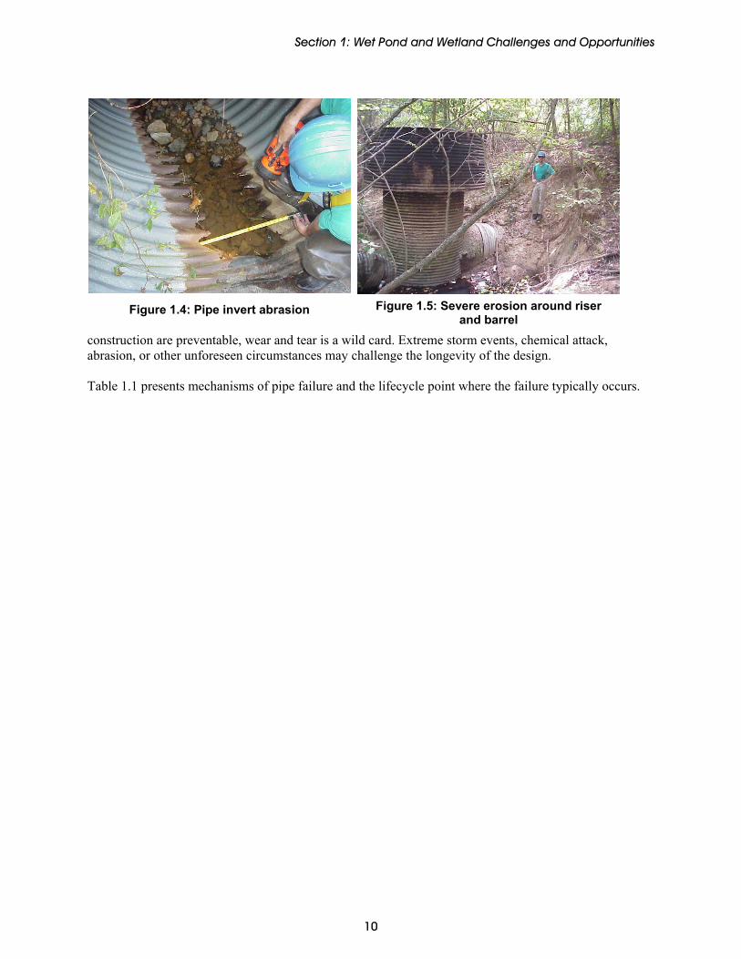
Pipe Repairs Pipes and riser structures are designed to convey stormwater safely and at a controlled rate. If pipes or risers are damaged, these functions will be affected. Often, risers are made from the same materials as pipes, and therefore can be treated as such with respect to maintenance and repair. Pipes through the embankment – the principal spillway and other utilities – are designed to be watertight. If damaged, pipes may leak water into the embankment through holes or separated joints (Figure 1.4). This can lead to piping of water along the pipe, which results in erosion (Figure 1.5) and can lead to embankment failure. Pipe damage can occur at any point in a pond or wetland lifecycle and can be caused by improper dpoor construction, inadequate maintenance, or wear and tear. While problems with design and
2 Low flow orifices or openings pass baseflow and control detention time in ponds and wetlands.
9
Section 1: Wet Pond and Wetland Challenges and Opportunities
Figure 1.5: Severe erosion around riser and barrel
Figure 1.4: Pipe invert abrasion
construction are preventable, wear and tear is a wild card. Extreme storm events, chemical attack, abrasion, or other unforeseen circumstances may challenge the longevity of the design. Table 1.1 presents mechanisms of pipe failure and the lifecycle point where the failure typically occurs.
10

Section 1: Wet Pond and Wetland Challenges and Opportunities
Table 1.1: Mechanisms of Pipe Failure
Lifecycle Point Mechanism Design Construction Wear and Tear
Joint Separation The physical separation of different sections of pipe along the barrel typically caused by differential settlement or improper pipe compaction.
Buoyancy Failure Failure occurs because trapped air in the pipe creates uplift forces. This force can cause the ends of the pipe to bend upward or the entire culvert to be displaced.
Static and Dynamic Loading Overburdening (placing too much static weight on the pipe) or inappropriate dynamic loading (e.g. driving a heavy piece of equipment over a pipe with insufficient backfill) causes failure.
Material Compatibility Designs with several pipe materials may not bond well, especially if dissimilar pipe materials are placed in pre-cast forms on holes, and then grouted to be water-tight. Most non-cementatious materials do not bond well to concrete or masonry as these materials tend to shrink over time. It is common to see leaks in the control structures where plastic or steel pipes enter through concrete.
Installation Technique See Section 2 for description.
Insufficient Compaction See Section 2 for description.
Vandalism Acts include filling with rubble and debris and crushing exposed ends of plastic and clay piping.
Corrosion Fatigue Fatigue type cracking of metal caused by repeated or fluctuating stresses in a corrosive environment is characterized by shorter life than would be encountered as a result of either the repeated or fluctuating stress alone or the corrosive environment alone.
U/V Deterioration Plastic piping is susceptible to deterioration from sunlight and even UV resistant material will become brittle and fracture given enough exposure.
Freezing and Cracking Water pockets in the pipes, which are constantly exposed to surface water, freeze and thaw several times each winter, stressing and weakening the pipe.
Internal Corrosion Corrosion that occurs inside a pipe because of the physical, chemical, or biological interactions between the pipe and the water.
Abrasion Deterioration of a surface by the abrasive action of moving fluids - this is accelerated by the presence of solid particles or gas bubbles in suspension
11

Section 1: Wet Pond and Wetland Challenges and Opportunities
Vegetation Management Vegetation management involves sustaining the landscaping as designed and preventing the growth of unwanted species. There are three primary types of vegetation that require management and maintenance in stormwater ponds and wetlands: turf and grasses, wetland plantings, and trees and forested areas.
Figure 1.6: Mowed dry pond bottom
Turf and Grasses Native and non-native grasses are the most common vegetative stabilization used in stormwater pond and wetland construction today for reasons of aesthetics, ease of maintenance, and price (Figure 1.6). The root system of any vegetative cover holds the surface soil in place and protects the slopes from wind and surface runoff erosion. A regularly scheduled program of cutting and trimming of grass at facilities during the growing season will help to maintain a tightly knit turf and will also help prevent diseases, pests and the intrusion of weeds. Wetland Plantings Native wetland plants promote biological uptake of pollutants (Figure 1.7). Though natural propagation is desirable, vegetation will still need to be managed to meet the design goals. Depending on the design of the system, vegetation harvesting3 and control of aquatic plants (such as cattails and phragmites) may be required.
Trees and Forested Areas
Figure 1.7: Wetland vegetation
Trees are often planted for aesthetic, stabilization, and temperature control reasons. They have to be maintained to prevent clogging of orifices with debris and the spread to unwanted areas.
Vegetation management is probably the most frequent maintenance activity that occurs in association with the upkeep of stormwater ponds and wetlands. While the activity requires little expertise or special equipment, there are still important site conditions to be aware of in order to maintain a properly functioning stormwater pond or wetland. Examples of common vegetative problems include:
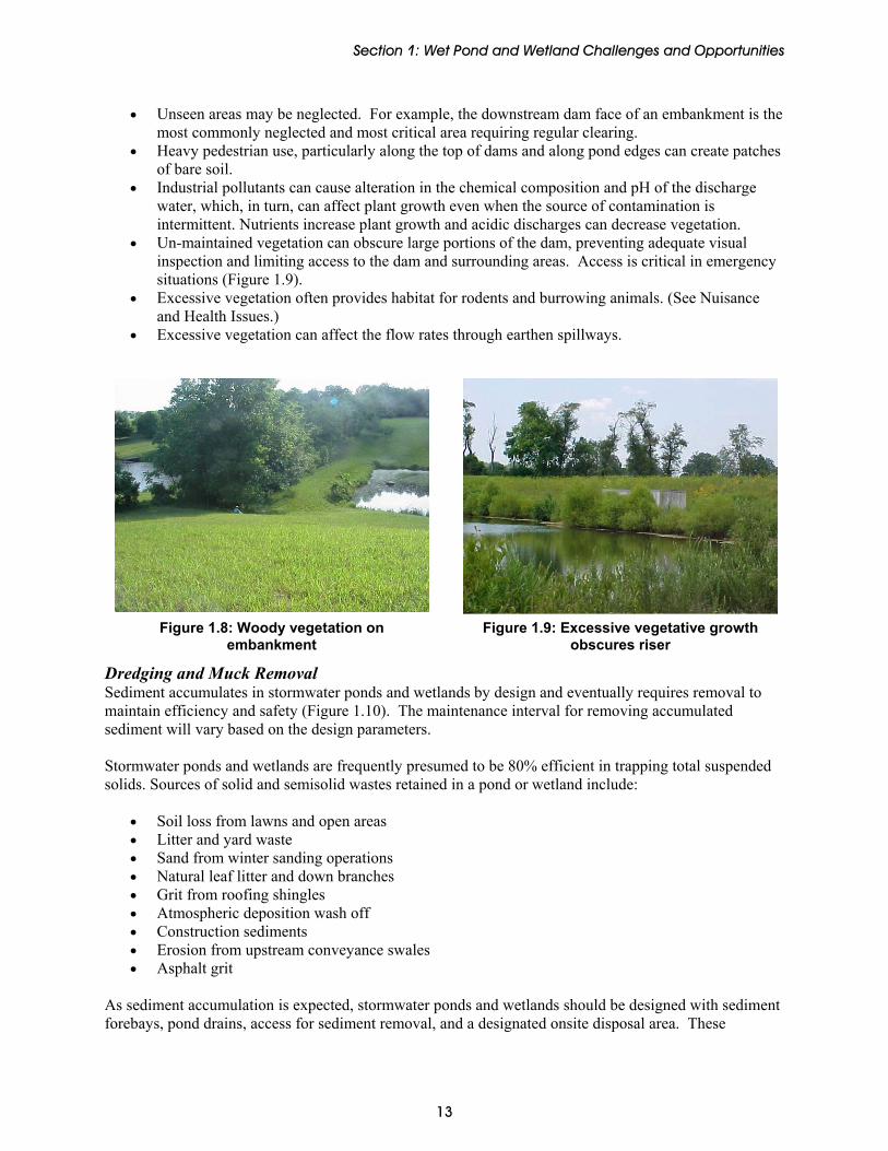
• Trees and brush with extensive woody root systems can destabilize dams, embankments, and side slopes due to the creation of seepage routes (Figure 1.8).
• Monolithic stands of cattails (Typha sp) and Common Reed (Phragmites australis) can take over shallow marsh wetlands and drainage swales, out-competing other useful native emergent plants that would otherwise establish more varied, mature marsh plant ecology. Nuisance aquatic weeds are like any other pest; they are opportunistic and invasive. Small shallow ponds provide optimal conditions for their proliferation.
• Misunderstanding of which areas of a stormwater pond or wetland require mowing or management can lead to under or over management.
3 Vegetation harvesting is removing vegetation on a routine basis and land applying it in an upland location. The purpose of harvesting is to remove plant material before winter die-off to prevent nutrients from reentering the water column and being flushed downstream.
12
Section 1: Wet Pond and Wetland Challenges and Opportunities
• Unseen areas may be neglected. For example, the downstream dam face of an embankment is the most commonly neglected and most critical area requiring regular clearing.
• Heavy pedestrian use, particularly along the top of dams and along pond edges can create patches of bare soil.
• Industrial pollutants can cause alteration in the chemical composition and pH of the discharge water, which, in turn, can affect plant growth even when the source of contamination is intermittent. Nutrients increase plant growth and acidic discharges can decrease vegetation.
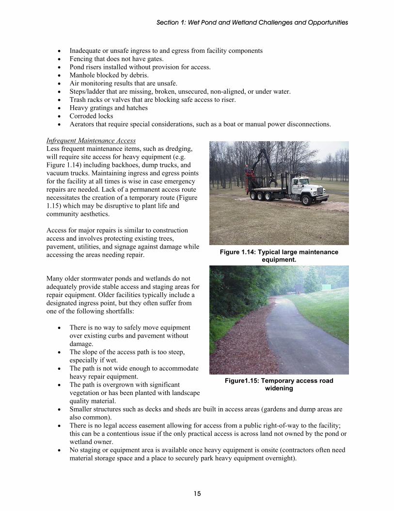
• Un-maintained vegetation can obscure large portions of the dam, preventing adequate visual inspection and limiting access to the dam and surrounding areas. Access is critical in emergency situations (Figure 1.9).
• Excessive vegetation often provides habitat for rodents and burrowing animals. (See Nuisance and Health Issues.)
• Excessive vegetation can affect the flow rates through earthen spillways.
Figure 1.8: Woody vegetation on embankment
Figure 1.9: Excessive vegetative growth obscures riser
Dredging and Muck Removal Sediment accumulates in stormwater ponds and wetlands by design and eventually requires removal to maintain efficiency and safety (Figure 1.10). The maintenance interval for removing accumulated sediment will vary based on the design parameters. Stormwater ponds and wetlands are frequently presumed to be 80% efficient in trapping total suspended solids. Sources of solid and semisolid wastes retained in a pond or wetland include:
• Soil loss from lawns and open areas • Litter and yard waste • Sand from winter sanding operations • Natural leaf litter and down branches • Grit from roofing shingles • Atmospheric deposition wash off • Construction sediments • Erosion from upstream conveyance swales • Asphalt grit
As sediment accumulation is expected, stormwater ponds and wetlands should be designed with sediment forebays, pond drains, access for sediment removal, and a designated onsite disposal area. These
13

Section 1: Wet Pond and Wetland Challenges and Opportunities
Figure 1.11: Muck removal and slope dressing by long reach backhoe
Figure 1.10: Sediment accumulation in a dry pond
considerations will reduce eventual costs of sediment removal, as major cost items in dredging include dewatering, transport of sediment for off-site disposal, re-establishment of wetland communities, and accessing the site (Figure 1.11). Ease of Access Access is needed to all parts of the stormwater treatment facility for inspection maintenance. Key access points include:
• Riser structure • Embankments • All outfalls and inlets • Forebays and pond bottoms • Aerators and electrical panels
Additionally, public access should be limited to only some pond or wetland components to prevent vandalism. Access for Regular Inspection and Maintenance: Frequent maintenance items usually involve small pieces of equipment such as mowers and light trucks. Access also involves facilitating inspector access to, into and through a stormwater pond or wetland to note items in need of repair. Figure 1.12 shows good maintenance access to a facility. Critical appurtenances should be easily and safely accessed for inspection and minor maintenance, such as lubricating a pond valve. Access must be provided to inspect for mosquito production and take appropriate actions when necessary. Figure 1.13 shows good manhole access.
Figure 1.12: Pond with good access to public road.
Typical problems that impede maintenance access include:
Figure 1.13: Ladder and steps in riser.
14
Section 1: Wet Pond and Wetland Challenges and Opportunities
• Inadequate or unsafe ingress to and egress from facility components • Fencing that does not have gates. • Pond risers installed without provision for access. • Manhole blocked by debris. • Air monitoring results that are unsafe. • Steps/ladder that are missing, broken, unsecured, non-aligned, or under water. • Trash racks or valves that are blocking safe access to riser. • Heavy gratings and hatches • Corroded locks • Aerators that require special considerations, such as a boat or manual power disconnections.
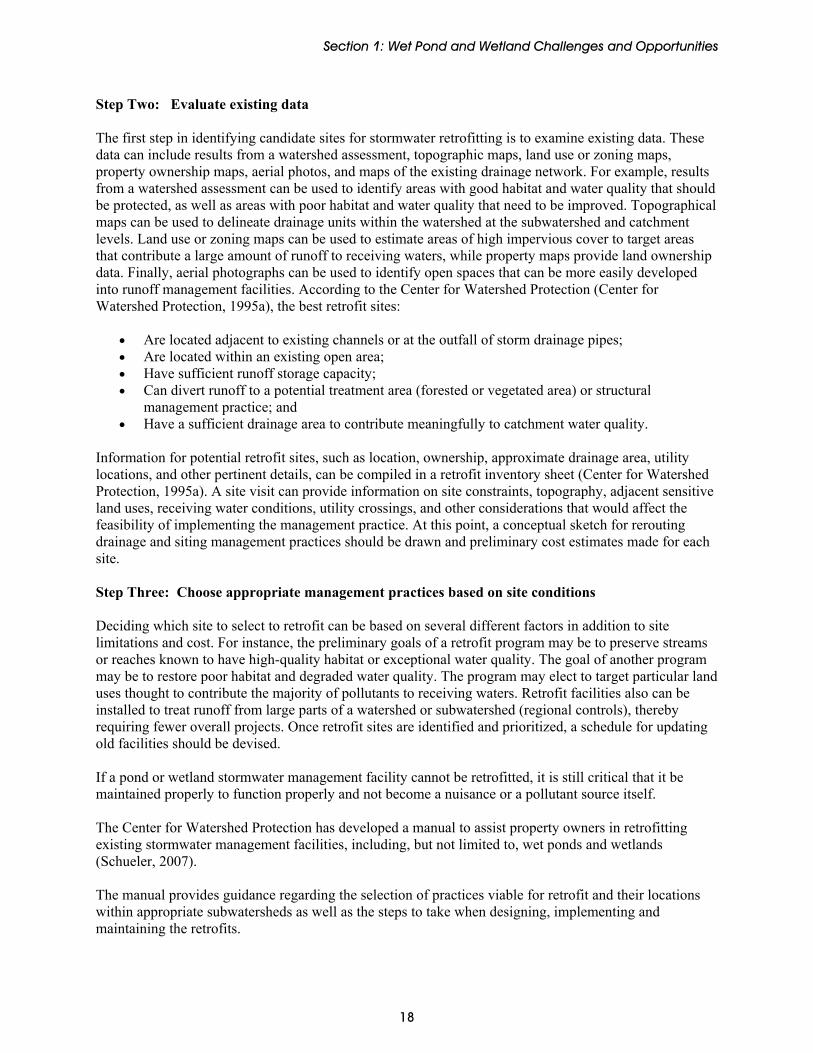
Infrequent Maintenance Access Less frequent maintenance items, such as dredging, will require site access for heavy equipment (e.g. Figure 1.14) including backhoes, dump trucks, and vacuum trucks. Maintaining ingress and egress points for the facility at all times is wise in case emergency repairs are needed. Lack of a permanent access route necessitates the creation of a temporary route (Figure 1.15) which may be disruptive to plant life and community aesthetics. Access for major repairs is similar to construction access and involves protecting existing trees, pavement, utilities, and signage against damage while accessing the areas needing repair. Figure 1.14: Typical large maintenance
equipment. Many older stormwater ponds and wetlands do not adequately provide stable access and staging areas for repair equipment. Older facilities typically include a designated ingress point, but they often suffer from one of the following shortfalls:
• There is no way to safely move equipment over existing curbs and pavement without damage.
• The slope of the access path is too steep, especially if wet.
• The path is not wide enough to accommodate heavy repair equipment. Figure1.15: Temporary access road
widening • The path is overgrown with significant vegetation or has been planted with landscape quality material.
• Smaller structures such as decks and sheds are built in access areas (gardens and dump areas are also common).
• There is no legal access easement allowing for access from a public right-of-way to the facility; this can be a contentious issue if the only practical access is across land not owned by the pond or wetland owner.
• No staging or equipment area is available once heavy equipment is onsite (contractors often need material storage space and a place to securely park heavy equipment overnight).
15

Section 1: Wet Pond and Wetland Challenges and Opportunities
Vandalism protection: Vandalism protection involves common sense measures such as chaining and locking mechanical components (valves and security manhole accesses). It also includes the use of well-designed trash racks to discourage vandalism and reduce clogging. Although there are many passive options to keep people away from a facility, including screening with vegetation and locating the pond or wetland out of eyesight, the most common method of exclusion is fencing. Fences can be damaged by many factors, including vandalism and storm events. Timely repair will maintain the security of the site and reduce potential liability. Appurtenances should be locked with key locks as opposed to more corrosion-prone combination locks. The design life of the typical lock left exposed to the elements is one to five years. They often become corroded and cannot be opened at time of inspection or maintenance. Therefore this often requires that the chain be cut and a new lock placed. For municipalities, one master key should open all stormwater facility locks to avoid confusion if keys are lost. Typical locations for locks include the following:
• Chaining all valves with hand wheels • Sluice gates • Entrance points through fencing
Damage of Mechanical Components Pond and wetland mechanical components tend to be simple and few in numbers. They include:
• Valves • Sluice gates and flap gates • Anti-vortex devices • Pumps • Access hatches • Aerators (fountains, bubblers, diffusers) • Electric control panels for aerators
These components should be inspected at least annually and repaired according to manufacturer’s recommendations. Mechanical components may be damaged as a result of:
Figure 1.16: Corroded plumbing and valve.
• Clogging • Sediment accumulation • Vandalism • Weathering or corrosion (Figure 1.16) • Extended use • Lack of preventative maintenance such as lubrication
Design considerations and preventative maintenance can address most of these issues. Failure to maintain these items could prevent the pond from functioning as designed, cause the problems described in the Clogging and Access sections, or, in the case of aerators, affect water quality.
16

Section 1: Wet Pond and Wetland Challenges and Opportunities
Nuisance Issues Rodents usually damage ponds or wetlands through burrowing or dam building. Burrowing may jeopardize embankment stability for dams and berms; beaver dam building reduces live storage and creates clogging problems. The following animals routinely cause destruction to embankments and berms: groundhogs/woodchucks, muskrats, prairie dogs, badgers, pocket gophers and Richardson ground squirrels. Animal burrows can deteriorate the structural integrity of dams, embankments and slopes (Figure 1.17). Muskrats in particular will burrow tunnels up to 6 inches in diameter.
Figure 1.17: Animal burrow in pond embankment.
Beaver activity in urban areas usually results in tree and vegetation mortality, flooding from dam building that causes water to encroach into unwanted areas, and impairment of stormwater management facilities. Beaver activity can be either an aesthetic issue that detracts from the visual appeal of the community, or a property damage issue that poses liability concerns. Management options for beaver control include trapping, dam and lodge removal, and the use of beaver “baffles.” Opportunities Owners of existing wet ponds or wetlands should evaluate them for retrofit opportunities to improve water quality benefits. Not all facilities can or should be retrofitted and the evaluation is based on a number of factors. Facilities that cannot be retrofit should be inspected and maintained to retain optimum performance with the least resource expenditure (see Section 2). The National Management Measures Guidance to Control Nonpoint Source Pollution from Urban Areas (EPA, 2005b) outlines the following steps for determining retrofit opportunities for existing ponds and wetlands: Step One: Identify, Prioritize, and Schedule Retrofit Opportunities In the watershed assessment phase of the urban runoff management cycle, watershed managers should identify waterbodies that have been degraded by urban runoff and prioritize them for restoration based on the costs and benefits for watershed stakeholders. One method to halt further degradation and initiate waterbody improvement is to retrofit existing runoff management practices or conveyance structures. It is important for watershed managers to have clear goals and realistic expectations for retrofitting existing structures. Each retrofit project should be planned in the context of a comprehensive watershed plan, and managers should have a clear set of objectives to ensure that the project results in measurable improvements in hydrologic, habitat, and/or water quality indicators.
17
Section 1: Wet Pond and Wetland Challenges and Opportunities
18
Step Two: Evaluate existing data The first step in identifying candidate sites for stormwater retrofitting is to examine existing data. These data can include results from a watershed assessment, topographic maps, land use or zoning maps, property ownership maps, aerial photos, and maps of the existing drainage network. For example, results from a watershed assessment can be used to identify areas with good habitat and water quality that should be protected, as well as areas with poor habitat and water quality that need to be improved. Topographical maps can be used to delineate drainage units within the watershed at the subwatershed and catchment levels. Land use or zoning maps can be used to estimate areas of high impervious cover to target areas that contribute a large amount of runoff to receiving waters, while property maps provide land ownership data. Finally, aerial photographs can be used to identify open spaces that can be more easily developed into runoff management facilities. According to the Center for Watershed Protection (Center for Watershed Protection, 1995a), the best retrofit sites:
• Are located adjacent to existing channels or at the outfall of storm drainage pipes; • Are located within an existing open area; • Have sufficient runoff storage capacity; • Can divert runoff to a potential treatment area (forested or vegetated area) or structural
management practice; and • Have a sufficient drainage area to contribute meaningfully to catchment water quality.
Information for potential retrofit sites, such as location, ownership, approximate drainage area, utility locations, and other pertinent details, can be compiled in a retrofit inventory sheet (Center for Watershed Protection, 1995a). A site visit can provide information on site constraints, topography, adjacent sensitive land uses, receiving water conditions, utility crossings, and other considerations that would affect the feasibility of implementing the management practice. At this point, a conceptual sketch for rerouting drainage and siting management practices should be drawn and preliminary cost estimates made for each site. Step Three: Choose appropriate management practices based on site conditions Deciding which site to select to retrofit can be based on several different factors in addition to site limitations and cost. For instance, the preliminary goals of a retrofit program may be to preserve streams or reaches known to have high-quality habitat or exceptional water quality. The goal of another program may be to restore poor habitat and degraded water quality. The program may elect to target particular land uses thought to contribute the majority of pollutants to receiving waters. Retrofit facilities also can be installed to treat runoff from large parts of a watershed or subwatershed (regional controls), thereby requiring fewer overall projects. Once retrofit sites are identified and prioritized, a schedule for updating old facilities should be devised. If a pond or wetland stormwater management facility cannot be retrofitted, it is still critical that it be maintained properly to function properly and not become a nuisance or a pollutant source itself. The Center for Watershed Protection has developed a manual to assist property owners in retrofitting existing stormwater management facilities, including, but not limited to, wet ponds and wetlands (Schueler, 2007). The manual provides guidance regarding the selection of practices viable for retrofit and their locations within appropriate subwatersheds as well as the steps to take when designing, implementing and maintaining the retrofits.

Section 2: Inspection and Maintenance of Existing Ponds and Wetlands
Section 2: Inspection and Maintenance of Existing Ponds and Wetlands Long-term functioning of stormwater BMPs requires periodic inspections, routine maintenance, and corrective actions. Often the efforts of both community stakeholders and stormwater management professionals are necessary to insure the management practices are operating as they were intended. Inspections Inspections help the stormwater manager monitor the safety, longevity, and effectiveness of these practices over time. This section outlines some tips for inspecting ponds and wetlands, focusing on the inspection frequency, inspection checklists, documentation photographs, and repair item documentation. Inspectors Ongoing post-construction inspections of stormwater ponds and wetlands can be conducted by a variety of stakeholders including:
Professional engineers and specialized contractors Municipal Inspectors and Maintenance Crews Commercial, Institutional, and Municipal Owners Concerned citizens and adjacent homeowners Homeowners Associations Property Managers
Property owners should reach an agreement with the property management, maintenance team or landscaping contractor to conduct frequent inspection and maintenance items such as mowing, checking for clogs, and debris removal. Clearly identify the expectations so that the landscaping design is preserved for optimal stormwater treatment. Attentive landscapers, adjacent homeowners, and homeowner associations can be the first to identify potential problems. A homeowner checklist is included in Appendix B. Several local maintenance guidebooks aimed at citizens are also available on the SMRC website (www.stormwatercenter.net) under Program Resources, STP Maintenance, STP Maintenance Educational Materials. The range of experience needed to diagnose a problem during inspection is quantified below in Table 2.1. These skill levels are used to describe the inspection items in Table 2.2. Table 2.1: Inspection Skill Level Descriptions
Skill Level Description
0 No special skills or prior experience required, but some basic training via manual, video, or other materials is necessary.
1 Inspector, maintenance crew member or citizen with prior experience with ponds and wetlands
2 Inspector or contractor with extensive experience with pond and wetland maintenance issues
3 Professional engineering consultant
19

Section 2: Inspection and Maintenance of Existing Ponds and Wetlands
Inspection Frequency Ponds and wetlands should ideally be inspected on a monthly basis for minor items, and annually for major inspection items, such as structural components. In reality, many communities are unable to inspect all of their ponds this frequently, and a more typical scenario is providing inspection once every three years. This less frequent full inspection can be supplemented with a routine inspection conducted by a property owner or contractor responsible for maintenance. In the case of wetlands, an additional inspection may be required after the first year to ensure that wetland plantings remain viable. Table 2.2 shows the frequency timeline with typical inspection and maintenance items at these times. Inspection frequency may be refined by the maintenance history of the practice as generated by ground crews charged with maintenance and mowing, or other interested parties. The profile sheets referenced under maintenance items are provided in Section 3.
Table 2.2: Typical Inspection/Maintenance Frequencies for Ponds And Wetlands Frequency Inspection Items
(Skill Level) Maintenance Items
(Related Profile Sheet)
One time - After First Year
Ensure that at least 50% of wetland plants survive (0)
Check for invasive wetland plants (0)
Replant wetland vegetation (See M-4 Vegetation Management)
Monthly to Quarterly or After Major
Storms (>1”)
Inspect low flow orifices and other pipes for clogging (0)
Check the permanent pool or dry pond area for floating debris, undesirable vegetation (0)
Investigate the shoreline for erosion (0) Monitor wetland plant composition and health (0-1)
Look for broken signs, locks, and other dangerous items (0)
Mowing – minimum Spring and Fall (See M-4 Vegetation Management)
Remove debris (M-2 Clogging) Repair undercut, eroded, and bare soil
areas (See M-4 Vegetation Management)
Several Times per Hot/Warm
Season
Inspect stormwater ponds and stormwater wetlands for possible mosquito production (0-1)
Inspect for mosquitoes (See M-8 Nuisance Issues)
Semi-annual to annual
Monitor wetland plant composition and health (0-1)
Identify invasive plants (0-1) Ensure mechanical components are functional (0-1)
Setup a trash and debris clean-up day Remove invasive plants (See M-4 Vegetation Management)
Harvest wetland plants (See M-4 Vegetation Management)
Replant wetland vegetation (See M-4 Vegetation Management)
Repair broken mechanical components if needed (See M-7 Mechanical Components)
Every 1 to 3 years
Complete all routine inspection items above (0)
Inspect riser, barrel, and embankment for damage (1-2)
Inspect all pipes (2) Monitor sediment deposition in facility and forebay (2)
Pipe and Riser Repair (See M-3 Pipe Repair)
Complete forebay maintenance and sediment removal when needed (See M-5 Dredging and Muck Removal)
2-7 years Monitor sediment deposition in facility and forebay (2)
Complete forebay maintenance and sediment removal when needed (See M-5 Dredging and Muck Removal)
20
Section 2: Inspection and Maintenance of Existing Ponds and Wetlands
Table 2.2: Typical Inspection/Maintenance Frequencies for Ponds And Wetlands Frequency Inspection Items Maintenance Items
(Skill Level) (Related Profile Sheet)
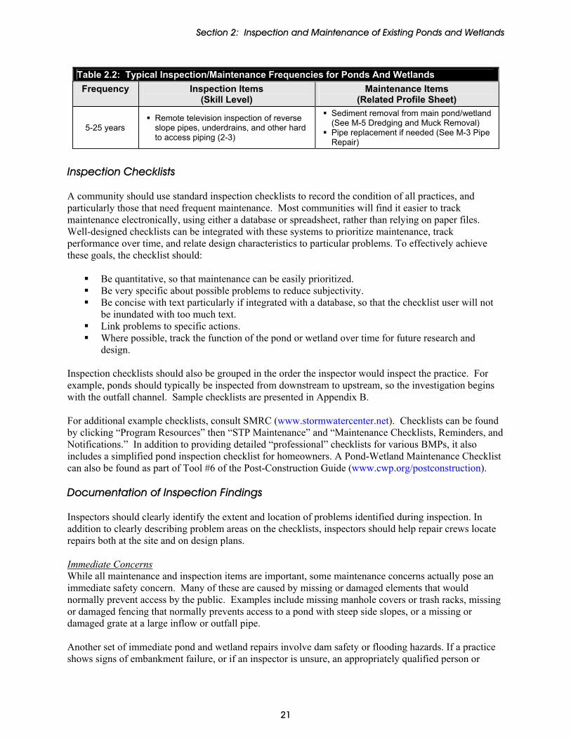
5-25 years Remote television inspection of reverse slope pipes, underdrains, and other hard to access piping (2-3)
Sediment removal from main pond/wetland (See M-5 Dredging and Muck Removal)
Pipe replacement if needed (See M-3 Pipe Repair)
Inspection Checklists A community should use standard inspection checklists to record the condition of all practices, and particularly those that need frequent maintenance. Most communities will find it easier to track maintenance electronically, using either a database or spreadsheet, rather than relying on paper files. Well-designed checklists can be integrated with these systems to prioritize maintenance, track performance over time, and relate design characteristics to particular problems. To effectively achieve these goals, the checklist should:
Be quantitative, so that maintenance can be easily prioritized. Be very specific about possible problems to reduce subjectivity. Be concise with text particularly if integrated with a database, so that the checklist user will not
be inundated with too much text. Link problems to specific actions. Where possible, track the function of the pond or wetland over time for future research and
design. Inspection checklists should also be grouped in the order the inspector would inspect the practice. For example, ponds should typically be inspected from downstream to upstream, so the investigation begins with the outfall channel. Sample checklists are presented in Appendix B. For additional example checklists, consult SMRC (www.stormwatercenter.net). Checklists can be found by clicking “Program Resources” then “STP Maintenance” and “Maintenance Checklists, Reminders, and Notifications.” In addition to providing detailed “professional” checklists for various BMPs, it also includes a simplified pond inspection checklist for homeowners. A Pond-Wetland Maintenance Checklist can also be found as part of Tool #6 of the Post-Construction Guide (www.cwp.org/postconstruction). Documentation of Inspection Findings Inspectors should clearly identify the extent and location of problems identified during inspection. In addition to clearly describing problem areas on the checklists, inspectors should help repair crews locate repairs both at the site and on design plans. Immediate Concerns While all maintenance and inspection items are important, some maintenance concerns actually pose an immediate safety concern. Many of these are caused by missing or damaged elements that would normally prevent access by the public. Examples include missing manhole covers or trash racks, missing or damaged fencing that normally prevents access to a pond with steep side slopes, or a missing or damaged grate at a large inflow or outfall pipe. Another set of immediate pond and wetland repairs involve dam safety or flooding hazards. If a practice shows signs of embankment failure, or if an inspector is unsure, an appropriately qualified person or
21

Section 2: Inspection and Maintenance of Existing Ponds and Wetlands
engineer should be called in to investigate the situation immediately. Similarly, cracks in a concrete riser that drains a large area may pose a dam safety threat. As-built Drawings The inspector should bring a copy of the as-built plan of the practice to mark potential corrections and problem areas on this plan. The marked up as-built plan should be stored either digitally or in a paper file system so that it can be brought out to confirm that maintenance was performed correctly on the follow-up inspection. Photographs Inspectors should take a core set of documentation photographs of practices being inspected. In addition, specific problem areas should be photo documented. A recommended set of core photographs for ponds and wetlands include:
• Vehicle access points. • Overview of practice. • Overview of principal spillway structure. • Upstream face of dam embankment. • Downstream face of dam embankment. • Outfall to practice and downstream outfall from practice. • Emergency spillway (if applicable).
In addition, because of the large number of photographs that will likely be generated, a digital camera should be used when possible to allow photographs to be stored electronically. (In advanced database programs, these photographs can be retrieved digitally). Finally, photographs should be named using a standard convention. The photograph name should indicate the practice identification number, feature (or problem) being photographed, and date of photograph. Field Marking Inspectors can highlight key areas of concern with spray paint or other marker. This is particularly useful for problems that may otherwise be difficult to find by others. Marking should be used as discretely as possible. For example, only dots sprayed at the base of trees should be used to mark limits of clearing for vegetation removal. Figures 2.1 to 2.4 show examples of helpful spray paint markings.
Figure 2.1: Marking outfall deficiencies. Figure 2.2: Marking trees to be removed.
22

Section 2: Inspection and Maintenance of Existing Ponds and Wetlands
Figure 2.3: Marking pipe joint separation
Figure 2.4: Marking a hole in gabion fabric
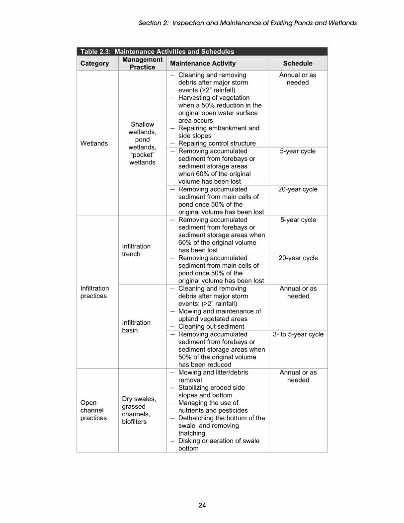
Routine Maintenance In addition to routine inspection, routine maintenance needs to be performed to maintain the function of the control structure. Runoff treatment controls require specific maintenance activities at varying schedules. The cost and time commitment should be planned for all maintenance activities delegated to a responsible party, regardless of whether it is a contractor, local municipality, or community stakeholder. Table 2.3 describes maintenance activities, and schedules for several categories of stormwater management strategies.
Table 2.3: Maintenance Activities and Schedules
Category Management Practice Maintenance Activity Schedule
— Cleaning and removing debris after major storm events (>2” rainfall)
— Harvesting of vegetation when a 50% reduction in the original open water surface area occurs
— Repairing embankment and side slopes
— Repairing control structure
Annual or as needed
— Removing accumulated sediment from forebays or sediment storage areas when 60% of the original volume has been lost
5-year cycle Ponds
Extended detention
ponds, wet ponds,
multiple pond systems, “pocket” ponds
— Removing accumulated sediment from main cells of pond once 50% of the original volume has been lost
20-year cycle
23
Section 2: Inspection and Maintenance of Existing Ponds and Wetlands
Table 2.3: Maintenance Activities and Schedules Management Category Maintenance Activity Schedule Practice
— Cleaning and removing debris after major storm events (>2” rainfall)
— Harvesting of vegetation when a 50% reduction in the original open water surface area occurs
— Repairing embankment and side slopes
— Repairing control structure
Annual or as needed
— Removing accumulated sediment from forebays or sediment storage areas when 60% of the original volume has been lost
5-year cycle Wetlands
Shallow wetlands,
pond wetlands, “pocket” wetlands
— Removing accumulated sediment from main cells of pond once 50% of the original volume has been lost
20-year cycle
— Removing accumulated sediment from forebays or sediment storage areas when 60% of the original volume has been lost
5-year cycle
Infiltration trench — Removing accumulated
sediment from main cells of pond once 50% of the original volume has been lost
20-year cycle
— Cleaning and removing debris after major storm events; (>2” rainfall)
— Mowing and maintenance of upland vegetated areas
— Cleaning out sediment
Annual or as needed
Infiltration practices
Infiltration basin — Removing accumulated
sediment from forebays or sediment storage areas when 50% of the original volume has been reduced
3- to 5-year cycle
Open channel practices
Dry swales, grassed channels, biofilters
— Mowing and litter/debris removal
— Stabilizing eroded side slopes and bottom
— Managing the use of nutrients and pesticides
— Dethatching the bottom of the swale and removing thatching
— Disking or aeration of swale bottom
Annual or as needed
24

Section 2: Inspection and Maintenance of Existing Ponds and Wetlands
Table 2.3: Maintenance Activities and Schedules Management Category Maintenance Activity Schedule Practice
— Scraping of swale bottom, and removal of sediment to restore original cross-section and infiltration rate
— Seeding or installing sod to restore ground cover (use proper erosion and sediment control)
5-year cycle
— Removing trash and debris from control openings
— Repairing leaks from the sedimentation chamber or deterioration of structural components
— Removing the top few inches of sand, and cultivation of the surface, when filter bed is clogged
Annual or as needed
Sand filters — Cleaning out the accumulated sediment from filter bed chamber once depth exceeds approximately ½ inch, or when the filter layer will no longer draw down within 24 hours
— Cleaning out the accumulated sediment from sedimentation chamber once depth exceeds 12 inches
3- to 5-year cycle
— Repairing eroded areas — Mulching of void areas — Removing and replacing all
dead and diseased vegetation
— Watering of plant material
Biannual or as needed
Bioretention
— Removing mulch and applying a new layer
Annual
Filtration practices
Filter strips
— Mowing and removing litter/debris
— Managing the use of nutrients and pesticides
— Aerating the soil on the filter strip
— Repairing eroded or sparse grass areas
Annual or as needed
25

Section 2: Inspection and Maintenance of Existing Ponds and Wetlands
26
Maintenance Activities Along with routine maintenance, specific activities for maintaining stormwater ponds and wetlands are detailed in the profile sheets in Section 3, which are organized by the top eight maintenance concerns introduced in Section 1. Each profile sheet provides the following:
Problems to Inspect For Corrective Actions Cautions and Safety Tips
In addition, a subjective rating of skill level is presented with many of the maintenance activities to aid the program managers and responsible parties in understanding the severity of the problems described. Ratings and descriptions of the required skill levels can be found in Table 2.4 below. Table 2.4: BMP Maintenance Skill Level Descriptions
Skill Level Description
0 No special skills are required but some basic training via manual, video, or other materials is necessary.
1 Ordinary maintenance crew skill level. 2 Contractor familiar with pond and wetland maintenance issues. 3 Professional engineering consultant.
Lastly, Appendix A provides useful unit cost information for specific maintenance activities along with typical maintenance frequencies to be expected.
Section 2: Maintenance Activity Profile Sheets M-1 Permanent Pool
Maintenance Activity Profile Sheets
M-1 PERMANENT POOL..................................................................................................................... 28 M-2 CLOGGING.................................................................................................................................. 31 M-3 PIPE REPAIRS ............................................................................................................................. 33 M-4 VEGETATION MANAGEMENT.................................................................................................... 38 M-5 DREDGING AND MUCK REMOVAL ............................................................................................ 42 M-6 ACCESS ....................................................................................................................................... 45 M-7 MECHANICAL COMPONENTS .................................................................................................... 47 M-8 NUISANCE ISSUES....................................................................................................................... 50
27

Section 2: Maintenance Activity Profile Sheets M-1 Permanent Pool
M-1 Permanent Pool
Problems to Inspect For
INSPECTION TIP: Stormwater ponds and wetlands often have higher than normal water surface elevations after storm events, sometimes for a number of days. This is a normal part of the design. Consider the last significant rainfall event when determining your inspection schedule. Try to avoid examining permanent pool levels within 2 to 3 days of a significant rainstorm to give the facility time to discharge the runoff temporarily stored in the pond. Exceptions to this rule apply if vortexing or another problem that may be more apparent at higher stage is suspected.
An important aspect of any pond or wetland inspection is having sufficient background information. In the absence of familiarity, a good set of as-built drawings can present a considerable amount of information about the way a pond was built and how it should function. Construction drawings or as-built drawings will include anticipated levels for permanent pools and sizes and locations of orifices. The best tool for confirming pool elevation fluctuation is familiarity. Abnormally high or low levels are more likely to be noticed in a pond that has been frequently inspected at normal levels. Signs that the permanent pool is too high include:
Water levels remain high for more than 2 or 3 days after a storm.
Pond edges normally visible are covered in water and plant species normally above permanent pool are now immersed in water.
If a stormwater pond or wetland is well constructed, with an adequately sized and protected low flow orifice, it will only suffer from an abnormally high pool when outside forces act on it. Examples are clogging, vandalism (damaged riser or low flow valve being opened), or rodent activity. Signs that the permanent pool is too low include:
Stain marks on the riser or flow control structure. Exposure of a non-vegetated pond bottom around the pool perimeter.
To review a dam embankment for possible seepage, look at the color of the vegetation as well as changes in the plant species present and their density, particularly in dry weather. These changes may indicate seepage or leaking on the downstream dam face. Embankment leaks on the downstream side of a berm or dam are usually easily discovered if the vegetative cover has been recently mowed and the slope is not too steep (generally, 2H:1V or flatter). Leaks on the upstream dam face are usually impossible to locate visually, unless it is at the surface (such as a flooded animal burrow) or there is an active vortex. Slow leaks that are only apparent over long time periods are particularly difficult to observe and may require a dye test or complete pond dewatering. Often, inspections of stormwater ponds and wetlands falsely report leaks during warm weather when droughts or improper water budget analysis may be the problem. This latter scenario makes a pond prone to frequent lowered pools due to natural evaporation.
28

Section 2: Maintenance Activity Profile Sheets M-1 Permanent Pool
Conversely, larger facilities or facilities fed by constant inflow (surface streams, springs, or seeps) may have leaks or excessive seepage that is masked by the apparent normal permanent pool supported by a strong water source. Recorded measurements over time are the best way to confirm this problem. Corrective Actions Fixing the problems associated with permanent pool fluctuation can vary in difficulty, from relatively simple to complex and expensive. Regardless of the level of skill required for fixing the problem, only properly trained and authorized personnel should perform the maintenance. Table M1.1 includes a list of problems, potential solutions, a subjective analysis of problem classification, and an estimate of the skill level recommended to correct problems associated with permanent pool issues. Estimated costs to fix the types of problems outlined here are included in the Maintenance Cost / Frequency Table in Appendix A. Table M1.1: Permanent Pool Fluctuation Diagnoses
Finding Solution Classification Level of Skill Recommended
Clogged low flow Clear low flow, install trash rack if not present or inadequate. See M-2 – Clogging.
Minor maintenance
(0) See cautions in
M-2.
Low flow or pond drain valve opened
Shut valve and lock shut with chain and lock. See M-2 – Clogging.
Minor maintenance
(0) See cautions in
M-2. Rodent activity (dams, lodges, burrows)
Fill burrows. See M-8 – Nuisance Issues Minor to major repair (1)
Leak in riser Seal leak. See M-3 – Pipe Repairs. Major repair (2)
Leak in barrel Seal leak. See M-3 – Pipe Repairs. Major repair (2)
Leak in upstream dam face or pond bottom
Drain remainder of permanent pool and install waterproof liner; dye test recommended.
Major repair (2)
Leak or seepage in downstream dam face
Dye test recommended; seal leak source if found; liner may need to be installed and dam or principal spillway repair or replacement may be required depending on leak severity.
Major repair (3)
Vortexing1
Consider a call to civil authorities immediately as dam failure may be imminent and down stream evacuation may be necessary; do not attempt to repair without professional help.
Usually major repair (3)
Inspection frequency beyond typical annual inspection should be set by the pond or wetland maintenance history and/or its use. For example, ponds with chronic clogging due to beaver activity should be put on a more frequent inspection schedule.
1 Swirling action of water caused by submerged orifice flow, usually in the vicinity of the dam, riser or principal spillway.
29
Section 2: Maintenance Activity Profile Sheets M-1 Permanent Pool
30
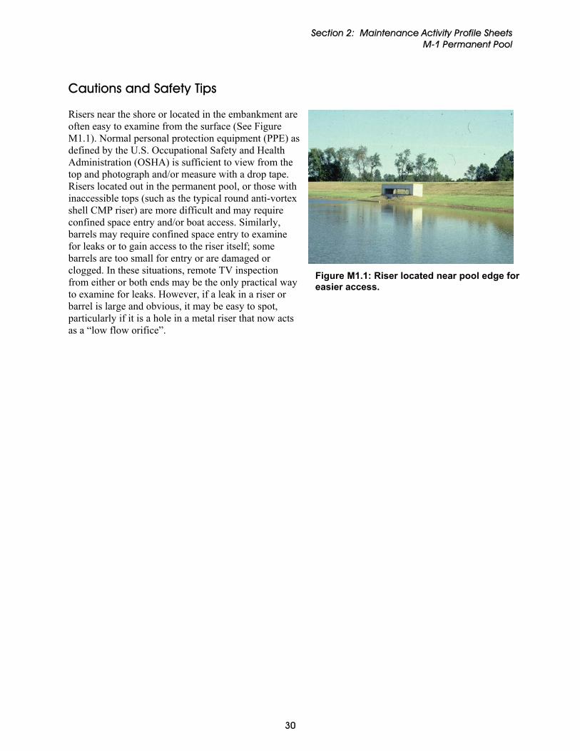
Cautions and Safety Tips Risers near the shore or located in the embankment are often easy to examine from the surface (See Figure M1.1). Normal personal protection equipment (PPE) as defined by the U.S. Occupational Safety and Health Administration (OSHA) is sufficient to view from the top and photograph and/or measure with a drop tape. Risers located out in the permanent pool, or those with inaccessible tops (such as the typical round anti-vortex shell CMP riser) are more difficult and may require confined space entry and/or boat access. Similarly, barrels may require confined space entry to examine for leaks or to gain access to the riser itself; some barrels are too small for entry or are damaged or clogged. In these situations, remote TV inspection from either or both ends may be the only practical way to examine for leaks. However, if a leak in a riser or barrel is large and obvious, it may be easy to spot, particularly if it is a hole in a metal riser that now acts as a “low flow orifice”.
Figure M1.1: Riser located near pool edge for easier access.

Section 2: Maintenance Activity Profile Sheets M-2 Clogging
M-2 Clogging
Problems to Inspect For External clogging can easily be identified through routine visual inspection. Clogging within low flow pipes and underdrains can be more difficult to find. A well functioning opening and trash rack should be clear of debris. Trash racks should show little or no corrosion and should be completely visible. Examine design or as-built records to determine which weir/orifice is supposed to set the permanent pool.
Figure M2.1: Clogged valve.
Record water surface elevations by leaving a stake or marker at a high water mark and recheck at regular intervals to determine if pond or wetland permanent pool levels are staying higher than designed for longer periods than expected following a rainfall event (see Profile Sheet M-1). If pool levels are higher than expected for long durations, then a clogged low flow pipe or orifice, or internal clogging of a low flow drain may be the problem. Corrective Actions Trash and debris removal should occur during the regularly scheduled inspection and maintenance to reduce the chance of outlet structures, trash racks, and other components becoming clogged and inoperable during storm events. Proper preventative maintenance includes removal of debris from pond bottoms, embankments and side slopes, perimeter areas, and access areas that can lead to clogging, as well as debris jams at outlet structures and trash racks.
Figure M2.2: Clogged low flow orifice (before maintenance).
Metal trash racks should be inspected, and any exposed steel should be brushed free of corrosion andcoated or spray coated with protectant or water sealant.
31
Section 2: Maintenance Activity Profile Sheets M-2 Clogging
32
Techniques for removing clogs depend on the accessibility and severity of the clog. They include:
Manual removal of debris by hand or by machine Jetting, back flushing, or routing a clogged pipe. High velocity spray and hydraulic head pressure
devices include high velocity jet cleaners, cleaning balls, and hinged disc cleaners. Sediment or muck removal around the low flow structure, to locate the opening and return it to
design conditions. (See M-5 – Dredging and Muck Removal) A professional diver may be needed for deeply clogged facilities. Dewatering of facility via pumping or other means to reveal the source of clogging and allow
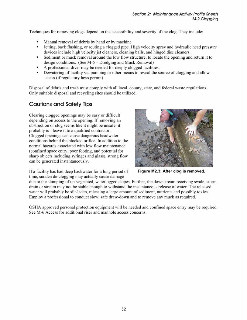
access (if regulatory laws permit). Disposal of debris and trash must comply with all local, county, state, and federal waste regulations. Only suitable disposal and recycling sites should be utilized. Cautions and Safety Tips Clearing clogged openings may be easy or difficult depending on access to the opening. If removing an obstruction or clog seems like it might be unsafe, it probably is - leave it to a qualified contractor. Clogged openings can cause dangerous headwater conditions behind the blocked orifice. In addition to the normal hazards associated with low flow maintenance (confined space entry, poor footing, and potential for sharp objects including syringes and glass), strong flow can be generated instantaneously. If a facility has had deep backwater for a long period of time, sudden de-clogging may actually cause damage due to the slumping of un-vegetated, waterlogged slopes. Further, the downstream receiving swale, stormdrain or stream may not be stable enough to withstand the instantaneous release of water. The released water will probably be silt-laden, releasing a large amount of sediment, nutrients and possibly toxics. Employ a professional to conduct slow, safe draw-down and to remove any muck as required.
Figure M2.3: After clog is removed.
OSHA approved personal protection equipment will be needed and confined space entry may be required. See M-6 Access for additional riser and manhole access concerns.
Section 2: Maintenance Activity Profile Sheets M-3 Pipe Repairs
M-3 Pipe Repairs
Problems to Inspect For Pipes are the most challenging feature of ponds and wetlands to thoroughly inspect. Repairs are often expensive and require specialized equipment. Table M3.1 presents a summary of maintenance concerns typical for different pipe materials. Following Table M3.1 are a number of inspection tips to inform an inspector or lay person about things to look for with respect to pipes when inspecting stormwater ponds and wetlands:
Table M3.1: Common Pipe Uses, Material, and Maintenance Concerns Use Most Common Material Typical Maintenance Concerns
Principal spillway or barrel CSP and RCP Scour damage, leaking joints, misaligned joints
Under drains, internal drains PVC, HDPE and Clay Filter media failure, crushing
Inlets RCP and CSP Blockages, frost heave, undercutting
Hydraulic control All types Clogging, corrosion, vandalism
Quantity control CSP Construction rips and tears, misalignments and non-soil-tight joints
Notes: CSP – corrugated steel pipe; RCP – reinforced concrete pipe; PVC - polyvinyl chloride pipe; HDPE – high density polyethylene pipe
Figure M3.1: Improper pipe joint but rubber seal is visible.
Joint Tightness: All pipe sections should abut evenly with little or no gap. In particular, no barrel should leak. Barrel pipes for ponds should not pass soil or water. Corrugated steel pipe (CSP) joints should meet smoothly, be free of rough or jagged edges, and have a butyl rubber seal surrounding the outside of the joint (Figure M3.1). The seal should not be torn, dry-rotted or bulging. CSP joints are not expected to be watertight (only soil tight1) except when used as principal spillways. Figure M3.2 illustrates a joint that is neither soil nor watertight. Concrete bell and spigot pipe joints may have a gap up to the allowable dimension as described by local ordinance or as determined by the manufacturer. Joints are usually parged with high strength non-shrink grout, but this does not guarantee water
1 Soil tight means that pipe joints can pass water but they do not allow soil intrusion.
33

Section 2: Maintenance Activity Profile Sheets M-3 Pipe Repairs
tightness. The tongue and groove end sections of individual pipe sections should be free from damage, especially damage that exposes the underlying re-enforcing steel. Plastic and clay piping are used in small diameter applications such as underdrains and splitter pipes. high density polyethylene pipe (HDPE) piping is usually installed in long sections without joints but polyvinyl chloride pipe (PVC) is usually installed with a rubber-coated bell and spigot connections similar to reinforced concrete pipe (RCP). The use of clay pipes for the principal spillway is discouraged as clay joints are not watertight. Misalignment: One of the most common causes for repair is pipe misalignment (Figure M3.3). Misalignment is often apparent at or shortly after construction. Otherwise, alignment changes occur due to differential settlement, freeze-thaw cycles, or dynamic loads such as traffic.
Figure M3.2: Soil entering open pipe joint.
Figure M3.3: Misalignment in RCP (left and right) and CSP (center) applications.
Pitting and corrosion: Unprotected CSP usually has a relatively long design life on its soil side but is very susceptible to erosive scour, pitting and corrosion on its flow side, particularly along the invert of the pipe. Pitting is highly localized corrosion causing perforations large enough to infiltrate or exfiltrate water. Soil side design life often exceeds 50 years, but flow side design life is usually between 20 and 35 years before the first pitting appears. CSP manufacturers coat piping with various substances to lengthen design life such as bituminous asphalt, aluminum, or concrete poured along the invert of the pipe. Staining and Calcification: Rust stains inside RCP often indicate that acidic groundwater is leaching in through a crack or hole, slowly dissolving the steel rebar and precipitating it back into a form of ferrous oxide on the inside of the pipe (Figure M3.4). Once the anaerobic water comes in contact with the oxygen within the pipe interior the reaction occurs. These stains usually indicate that repairs should be made
Figure M3.4: Rust intrusion demonstrates improper
pipe joint. Figure M3.5: Calcification..
34

Section 2: Maintenance Activity Profile Sheets M-3 Pipe Repairs
to the pipe to stop the water from infiltrating the pipe. Calcification occurs when acidic water enters concrete cracks from the inside of the pipe, dissolving and reconstituting the hydrated Portland cement in the RCP (Figure M3.5). Calcification may or may not mean that a crack has breached the entire thickness of the pipe and adequate experience is necessary to determine when repairs are truly necessary. Root Intrusion: Root intrusion into pipe systems is an especially difficult and damaging phenomenon but fortunately is relatively easy to observe. Roots typically enter loose pipe joints and can cause clogging by snagging debris. Willows (Salix sp.) are notorious for root intrusion. By following the described pipe inspection tips above, the lay person or inspector can better understand the types of problems likely to be encountered during stormwater pond and wetland maintenance inspection. Once experience is gained in performing inspections, inspectors can foresee potential problems and plan preventive maintenance. Corrective Actions Fixing pipe problems can be approached from two directions: repair or replacement. Different methods for pipe repair and replacement are presented below, as well as a recommended skill level. All involve the need for professional contractor or engineer assistance. Consult an engineer to determine the most appropriate technique. Common pipe repair methods include: • Joint Sealing: In the injection grouting method, RCP leaking joints and concrete cracks can be sealed
with high strength non-shrink grout or epoxy. Holes are drilled all the way through the pipe to the soil beyond. The grout is injected to the other side where it reacts with groundwater and hardens. This method is often used for difficult access areas such as a buried concrete pipe barrel joints. OSHA confined space entry training may be required. CSP joints are similarly sealed, except polyurethane foam water stop material is injected. Recommended skill level (3).
• Another joint sealing method utilizes an inflatable packer inserted into a pipeline to span a leaking
joint. Resin or grout is then injected into cracks and cavities until the joint is sealed, after which the packer is removed. This localized repair of pipes prevents leakage and further deterioration and may increase the structural strength of the pipeline. Recommended skill level (3).
• Invert Protection: This method involves protecting the lower segment of a corrugated metal pipe by
lining it with a smooth bituminous or concrete material that completely fills the corrugations. This approach is intended to give resistance to scour/erosion and to improve flow. Recommended skill level (2).
• Chemical Stabilization: Chemical stabilization involves isolating a length of pipeline between two
access points by sealing the access points. One or more compounds in solution are introduced into the pipe, and the surrounding ground produces a chemical reaction that forms a stable protective coating over cracks and cavities. Recommended skill level (3).
Pipe rehabilitation typically involves more intensive and comprehensive correction of pipe problems aimed at restoring or upgrading the performance of an existing pipe system. Often, rehabilitation is
35

Section 2: Maintenance Activity Profile Sheets M-3 Pipe Repairs
needed when there is major structural and/or hydraulic weakness. Common pipe rehabilitation methods, all involving the need for professional contractor or engineer assistance, include: • Folded Liners: A PVC or HDPE liner is folded to reduce its cross sectional area. The liner is pulled
into a failing pipe system and reverted to its original size using pressure and heat to form a tight fit with the host pipe wall. Recommended skill level (3).
• Cured-in-place pipe (CIPP): CIPP is a thin flexible tube of polymer or glass fiber fabric that is impregnated with thermoset resin and expanded by means of fluid pressure onto the inner wall of a defective pipeline before curing the resin to harden the material. Recommended skill level (3).
• Ferro-cement: Steel fabric mesh, usually in multiple layers, is fixed to the existing pipe, then covered in high strength grout. It is either placed in situ to form a structural lining (in large diameter pipes with human access) or pre-formed into segments for later installation. Recommended skill level (3).
• Pipe bursting: Also known as in-line expansion, this is a method by which the existing pipe is demolished and a new pipe is installed in its void. Recommended skill level (3).
• Pipe eating: A pipe replacement technique usually based on micro tunneling to excavate defective pipe with the surrounding soil as for a new installation. Recommended skill level (3).
• Pipe pulling: Method of replacing small diameter pipes where a new product pipe is attached to the existing pipe which is then pulled out of the ground. Recommended skill level (3).
• Slip-lining: Insertion of a new pipe by pulling or pushing it into the existing pipe and grouting the annular space. The new pipe may be continuous or a string of discrete pipe sections. The latter is also referred to as segmental slip-lining. Recommended skill level (3).
• Modified slip-lining: A range of techniques in which the liner is reduced in diameter before insertion into the carrier pipe, then restored to its original diameter, forming a close fit with the original pipe. Recommended skill level (3).
• Spray lining: A technique for applying a lining of cement mortar or resin by rotating a spray head, which is winched through the existing pipeline. Recommended skill level (3).
36

Section 2: Maintenance Activity Profile Sheets M-3 Pipe Repairs
37
Table M3.2 summarizes the limitations of the different types of pipe rehabilitation methods mentioned above. Table M3.2: Limitations of common pipe rehabilitation methods
Method Limitations
CIPP
• Bypass or diversion of flow required • Curing can be difficult for long pipe segments • Must allow adequate curing time • Defective installation may be difficult to rectify • Resin may clump together on bottom of pipe • Reduces pipe diameter
Pipe bursting
• Bypass or diversion of flow required • Insertion pit required • Percussive action can cause significant ground movement • May not be suitable for all materials
Slip-lining • Insertion pit required • Reduces pipe diameter • Not well suited for small diameter pipes
Modified Slip-lining
• Bypass or diversion of flow required • Cross section may shrink or unfold after expansion • Reduces pipe diameter • Infiltration may occur between liner and host pipe unless sealed • Liner may not provide adequate structural support
Cautions and Safety Tips Most stormwater pond and wetland pipe work can be visually inspected from a daylighted end or manhole access. However, some piping is difficult to inspect due to being buried, flooded, cramped, or deteriorated. In this case, inspection work should be left to qualified professionals who are versed in confined space entry and exit as defined and regulated by state and federal OSHA standards. Some piping is impossible to inspect manually (such as a 6-inch underdrain), and remote TV video inspection or complete unearthing are the only options.

Section 2: Maintenance Activity Profile Sheets M-4 Vegetation Management
M-4 Vegetation Management
Problems to Inspect For Vegetation management is the most frequent type of maintenance conducted on stormwater ponds and wetlands. In most instances, vegetation management is straightforward and does not require special expertise or equipment. However, if facilities have gone long periods of time without proper vegetation maintenance, then the level of effort and complexity of the activity can become significant. Telltale signs of vegetative problems include the following:
Standing water and emergent plant growth where none should be present
Monoculture vegetation in wetland
Poor or spotty grass growth or completely bare areas (Figure M4.1)
Soggy surfaces Excessive sedimentation at pond inlets or
outfalls with corresponding emergent plant growth (Figure M4.2)
Limited visibility or access to the principal spillway or embankment areas due to vegetation
Deep-rooted woody vegetation (trees and shrubs) on any areas of a dam
Woody vegetation growing in riprap on slope areas meant for erosion protection
Figure M4.1: Bare soils on embankment and slopes.
Signs of seepage around any tree stumps or decaying root systems on embankment areas
Changes in vegetative color, species or height due to possible groundwater or seepage problems
Areas where local residents have been dumping yard waste
Pond embankments with newly planted ornamental trees or shrubs not originally included in the design
Damaged or torn erosion control matting (ECM) Ruts or erosion channels in vegetated swales or
level spillways Tree or shrub growth in or around major pond
appurtenances such as the principal spillway
Figure M4.2: Excessive vegetation near an outfall.
38

Section 2: Maintenance Activity Profile Sheets M-4 Vegetation Management
Corrective Actions The following describe specific activities associated with maintaining the vegetation in and around stormwater ponds and wetlands as well as the recommended skill level of the person performing the maintenance in parentheses (reference Table 2.4): Grass and Turf
Figure M4.3: Representative mowing for wetland.
Consistent mowing and monitoring should control any unwanted vegetation. Typical mowing areas include pond bottoms (dry ponds), embankments, side slopes, perimeter areas, and access areas (Figure M4.3). The actual mowing requirements of an area should be tailored to the specific condition and grass type. Other actions to maintain grassed areas include de-thatching, soil conditioning, re-seeding, and periodic fertilization as necessary. Most grass is hardiest when maintained as an upland meadow, cut no shorter than 6 to 8 inches. If a more manicured look is desired, special attention to the health of the turf is needed. Grass should not be cut below 4 inches. Typical mowing schedules for grass on embankments are at least twice during both the spring and fall growing seasons and once during the summer. Recommended skill level (0). Vegetated Buffer A 10-foot unmowed vegetated buffer around the perimeter of the pond or wetland (exclusive of the dam embankment) may be established to filter pollutants from adjacent properties and help prevent shoreline erosion (Figure M4.4). Areas set aside for pond access such as fishing can be secured with stone, timber wall or one of many commercially available plastic retaining wall products. Recommended skill level (0). Vegetation Harvesting In stormwater wetlands, vegetation harvesting1 may be required. To perform wetland harvesting, selected plant materials are tagged for removal by a qualified professional, then cut and hauled to a disposal location. Recommended skill level (1 - 2).
Figure M4.4: Vegetated buffer.
1 Vegetation harvesting is removing vegetation on a routine basis and land applying it in an upland location. The purpose for vegetation harvesting is to remove plant material before winter die-off to prevent nutrients from reentering the water column and being flushed downstream.
39

Section 2: Maintenance Activity Profile Sheets M-4 Vegetation Management
Bare areas Vegetation can be established by any of five methods: mulching; allowing volunteer vegetation to become established; planting nursery vegetation; planting underground dormant parts of a plant; and seeding. Seeding can come in the form of broad-cast seeding, hydro-seeding or sodding. Donor soils from existing wetlands can be used to establish vegetation within a wetland. If the soil has become compacted, it will require aeration. Areas without grass or vegetation should be vigorously raked, backfilled if needed, and covered with topsoil. Disturbed areas should be seeded and mulched if necessary. A tall fescue grass seed is often recommended; however consult the local Natural Resources Conservation Service (NRCS) office for the best native mixes for the project location. Recommended skill level (0). Bare or monoculture stormwater pond and wetland slopes and bottoms offer the best opportunities to enhance areas with native trees, shrubs, and groundcovers to help the water soak into the ground. Select species that need little fertilizer or pest control and are adapted to specific site conditions. Again, contact your local NRCS office for guidance.
Figure M4.5: Unwanted vegetation - tree on embankment.
Unwanted vegetation Some vegetation, such as that on embankments (Figure M4.5), requires complete removal, including root masses, to ensure that it does not return; this is often best done with landscaping Brush HogsTM or small earthmoving equipment. Stump removal may also require tractor and chain. The removal of large trees may require the skills of a professional arborist. The use of herbicides should be avoided; however if deemed necessary, they must be applied by a state-licensed herbicide applicator. Recommended skill level range (0 - 2). Root removal Roots should be removed in the designated sections where root intrusion is a problem. To remove roots from a pipe, use mechanical devices such as rodding machines, bucket machines, and winches using root cutters and ‘porcupines’ or equipment such as high-velocity jet cleaners. Chemical root treatment is available but discouraged and herbicides must be applied by licensed applicators. Roots should be removed from the embankment to prevent their decomposition within the embankment. Excavate to remove roots, then plug or cap root voids. Recommended skill level (2). Dumping areas Grass clippings, leaves, soil and trash are often dumped directly into storm drain inlets or stormwater ponds and wetlands. Any of these items can lead to clogging, and leaves and grass clippings release bacteria, oxygen consuming materials, and nutrients. Removal is easy assuming a suitable disposal area or trash pickup location is available. Posting signage explaining the importance of not dumping will help dissuade the good intentioned. Signage may also advise natural lawn care to minimize the use of chemicals and pesticides. Recommended skill level (0). Inadequate drainage slopes To promote proper conveyance and to prevent standing water, conveyances to and from ponds and wetlands should have a minimum slope of one to two percent. Inadequate slopes typically result in the conveyances filling with sediment and vegetation (Figure M4.6). Removal of muck and vegetation from
40
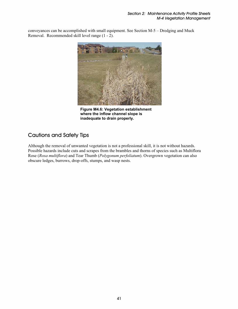
Section 2: Maintenance Activity Profile Sheets M-4 Vegetation Management
41
conveyances can be accomplished with small equipment. See Section M-5 – Dredging and Muck Removal. Recommended skill level range (1 - 2).
Figure M4.6: Vegetation establishment where the inflow channel slope is inadequate to drain properly.
Cautions and Safety Tips Although the removal of unwanted vegetation is not a professional skill, it is not without hazards. Possible hazards include cuts and scrapes from the brambles and thorns of species such as Multiflora Rose (Rosa multiflora) and Tear Thumb (Polygonum perfoliatum). Overgrown vegetation can also obscure ledges, burrows, drop-offs, stumps, and wasp nests.

Section 2: Maintenance Activity Profile Sheets M-5 Dredging and Muck Removal
M-5 Dredging and Muck Removal
Problems to Inspect For The need for dredging may be indicated by sediment plumes or deltas at storm drain inlets that feed stormwater ponds and wetlands, as most sediment falls to the pond floor quickly and within a short distance from storm drain inflow points (Figure M5.1). Alternatively, accumulated sediment can be measured through use of 1 a staff gauge .
t ater
ve
dredged for aesthetic value.
The best way to determine if a pond or wetland needs dredging is to perform a bathymetric study, which involves taking field measurements to calculate the volume of water within a pond or lake. The survey is similar to a topographic measurement of the contours below the permanent pool surface of a pond. The end result of the survey is a two-dimensional map indicating depth contours at all locations within the permanent pool. Bathymetric surveys indicate the amount of silor muck that has accumulated within a pond or lake; consequently, estimates of remaining stormwpond life, dredging volumes and associated costs can be made. A pond that appears full may still haadequate volume for settling suspended solids and for meeting stormwater management design criteria purposes, yet the owner may wish to have the pond
Figure M5.1 Sediment delta.
Bathymetric surveys require use of level rods, electric distance measurement equipment (EDM), small watercraft, sediment probes or depth finders to gather pond depth information (Figure M5.2). Usually a staff person measures the pond depth while in a canoe or johnboat. On shore, another staff uses EDM equipment to determine distance and azimuth (angle) measurements to the test location. Existing volume measurements can be compared against design volumes to determine the amount of muck requiring removal (Figure M5.3). If no previous design records exist, the procedure is basically the same, but additional sediment depth probing must be done to measure muck levels.
Figure M5.2: Measuring pond depth from canoe.
1 A staff gauge is a fixed marker rod that enables easy reading of sediment levels in a pond once the pond has been drained.
42

Section 2: Maintenance Activity Profile Sheets M-5 Dredging and Muck Removal
BATHYMETRIC STORAGE CURVE
118
120
122
124126
128
130
132
0 500 1000 1500 2000 2500
storage in cubic yards
wat
er s
urfa
ce e
leva
tion
(MSL
)
design storage bathymetric storage
Figure M5.3: Plot of elevation vs. storage for existing and design conditions.
Dredging needs for dry ponds are easier to identify. There may be a profusion of vegetation, particularly wetland species, at the bottom of the facility. Pilot channels may disappear due to the accumulation of sediment and trash. An obvious sign for quick action is a buried low flow opening. Sediment in a dry pond can also be measured with a preset staff gauge; but hand-taped or simple field surveys can also suffice. Corrective Actions In smaller ponds and wetlands, the pond water may be drawn down to a point where the residuals can begin to dry in place. After the material is dried, heavy equipment can remove the sediment from the bottom of the pond, a process referred to as mechanical dredging. Mechanical dredging may be accomplished with a standard or long reach backhoe, front end loader, dipper, bucket dredge, drag line or clamshell dredge (Figure M5.4). Care should be taken to minimize soil compaction around the pond or wetland that can be caused by the heavy machinery. Where dredging cannot be accomplished mechanically from the shore, it may be necessary to remove sediment using hydraulic dredging methods2. Larger ponds that cannot be drained are
Figure M5.4: Mechanical dredging with backhoe.
2 Hydraulic dredging uses a combination of water jet and vacuum to resuspend settled material and pump it to an upland location or other place for dewatering.
43

Section 2: Maintenance Activity Profile Sheets M-5 Dredging and Muck Removal
44
WETLAND DREDGING TIP: Maintenance dredging of a stormwater wetland can significantly damage the wetland community that has developed over the life of the practice, and may be met with resistance from regulators and adjacent property owners. Typically, if a wetland was constructed specifically for stormwater treatment and not as mitigation for other wetland impacts, owners can maintain them without permits. However, permitting authorities that have jurisdiction over the site should be informed prior to disturbing any wetland area for maintenance or other purposes. If a diverse native wetland plant community is present in a stormwater wetland, for maintenance purposes it may be advisable to scrape and stockpile the surface soil layer in a designated location for future reapplication. The surface layer may contain a variety of seeds thatcan be reapplied to help the wetland plant material reestablish after the excess sediment has been removed. If a non-native or invasive wetland plant community has been established, conduct removal with care or during a dormant season to discourage seed distribution.
often de-mucked via hydraulic suction or with the use of draglines operated from barges. In ponds not large enough to warrant hydraulic dredging, mechanical dredge methods are used and removed material is de-watered to minimize trucking requirements and potential spilling. Sediments from ponds and wetlands are usually dewatered and then disposed of onsite or land filled. It is typical to spread this material out on a site for use as a soil amendment. Onsite disposal usually entails digging a pit, wasting the muck material, covering the pit with previously removed topsoil and planting the appropriate native plantings. Once a dredge area disposal site is established, it cannot be used for structural support or building foundations as long-term settlement will occur. If on-site storage is not specified, sediment can typically be landfilled. Wet sediment is not accepted at many disposal sites; therefore, the material must be dewatered prior to disposal. This extra step adds to the cost and requires a location where wet material can be temporarily and safely placed to dry. If the practice drains a stormwater hotspot, such as a gas station, a Toxic Contaminant Leachate Procedure (TCLP) or other analytical analysis should be performed in accordance with receiving landfill requirements to determine if the removed sediment should be considered a hazardous waste. If the residual solids are determined to be hazardous, they must be managed according to Resource Conservation and Recovery Act of 1976 (RCRA), which requires either treatment to decrease the concentration of the hazardous constituent or disposal in a hazardous waste landfill. Cautions and Safety Tips Dredging and muck removal involve additional costs and safety considerations including proper disposal, confined space work, permitting and utility damage. This work is best left to general contractors and specialty maintenance companies with adequate training and bonding. The recommended skill level range for all dredging issues is (3)

Section 2: Maintenance Activity Profile Sheets M-6 Access
M-6 Access
Problems to Inspect For Inadequate access is typically discovered by inspectors or maintenance contractors who cannot enter a site or particular site features (e.g. risers). Inspectors should be cognizant of the types of equipment needed to maintain a stormwater pond or wetland, so they can note potential access issues (Figure M6.1). If potential access issues are noted up front, the maintenance contractor can be warned and can plan accordingly. Risers and manhole access can be particularly challenging and dangerous, particularly when access steps are missing (Figure M6.2) or no manhole access has been provided. In these cases, it is necessary to lower staff by winch once the atmosphere has been tested. Therefore, mandatory fall protection should be used when accessing risers or manholes.
Figure M6.1: Poor vehicle access.
If no manhole access is provided and water enters a riser through weirs or orifices that are too small to allow direct access, the riser may still be entered safely through the barrel (principal spillway) under certain conditions. In Howard and Montgomery Counties, Maryland, safe barrel access is defined by the following conditions:
Access is conducted by qualified confined space entry-trained staff (team of two with proper equipment).
Figure M6.2: Missing manhole step.
The barrel is open to daylight at both ends and no atmospheric dangers are present.
The diameter of the barrel is 36 inches or greater. There is little to no tailwater making access
unsafe, defined as blocking more than a third of the opening (Figure M6.3).
Given these conditions, the barrel may be crawled. Verbal contact should be kept with the crawler at all times. Each joint may be examined by hand for leaks and discontinuities. The inspector may enter the riser to inspect it once he or she has traversed the barrel.
Figure M6.3: Forced access location.
45

Section 2: Maintenance Activity Profile Sheets M-6 Access
46
Corrective Actions Many access issues are best addressed during the design of ponds and wetlands. However, there are routine maintenance activities that will also be required. Most notably, it is important and advisable to maintain primary access features as they were designed. This typically involves removal of woody vegetation from access roads and the upkeep of gravel areas. Risers with missing steps, manhole covers, or trash racks that present unsafe situations should also be repaired so that future access for inspection is not compromised. In some cases, where major work needs to be performed, temporary construction access for large, heavy equipment will need to be provided. In these situations, special
provisions should be taken to minimize impacts to adjacent areas, particularly if they are forested. Common tree protection measures include fencing that is sufficiently set off to provide protection of the critical root zone and protective sheathing (Figure M6.4).
Figure M6.4: Tree scar protection.
Heavy vehicle access can also impact areas with paving, curbs, and decking (Figure M6.5). It may also compact unpaved soil. For the mutual protection of both the owner and contractor, these access points should be clearly marked or flagged and then photographed prior to equipment arrival onsite. Temporary pavement protection devices include: Figure M6.5: Paved access road.
Steel sheeting Timbering and mats Stabilized stone and gravel construction accesses and mountable berms Unloading and ‘walking’ equipment in on rubber tires
If a fenced pond or wetland does not have vehicle gates large enough to accommodate heavy equipment, sections of fence will need to be temporarily removed to allow access. Cautions and Safety Tips Mandatory fall protection should be used when accessing risers or manholes. Risers and manholes may be missing access steps, and lowering staff by winch may be required once the atmosphere has been tested.
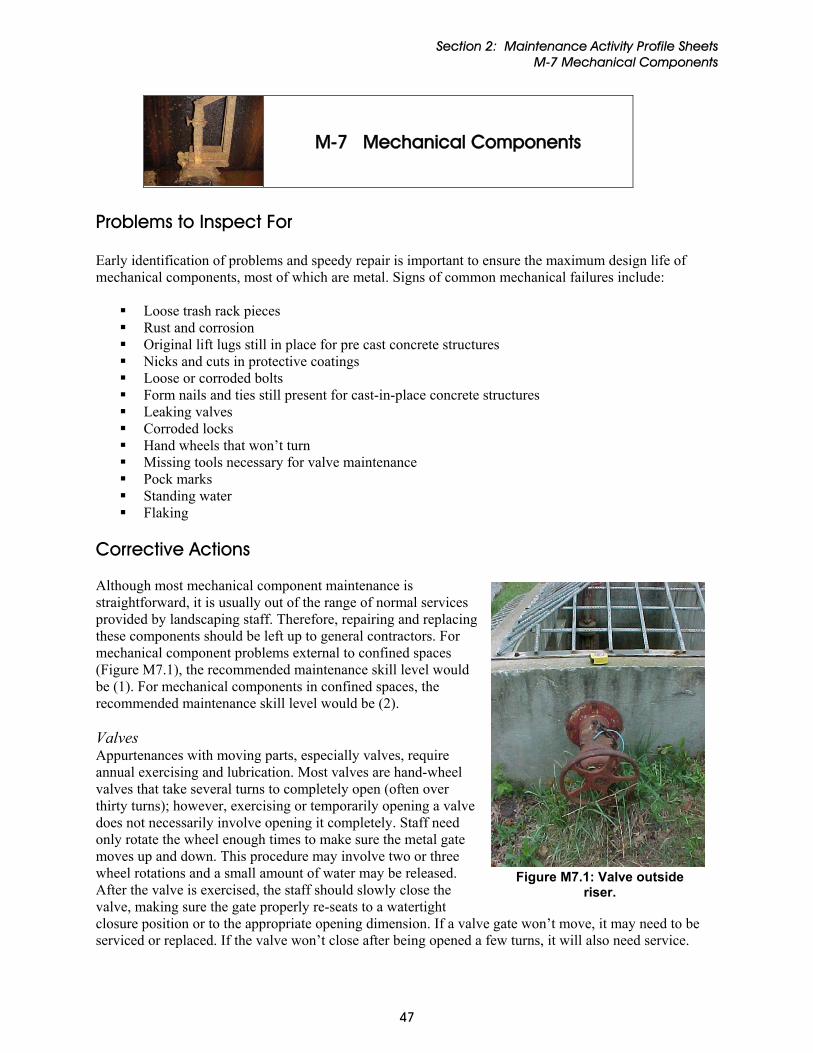
Section 2: Maintenance Activity Profile Sheets M-7 Mechanical Components
M-7 Mechanical Components
Problems to Inspect For Early identification of problems and speedy repair is important to ensure the maximum design life of mechanical components, most of which are metal. Signs of common mechanical failures include:
Loose trash rack pieces Rust and corrosion Original lift lugs still in place for pre cast concrete structures Nicks and cuts in protective coatings Loose or corroded bolts Form nails and ties still present for cast-in-place concrete structures Leaking valves Corroded locks Hand wheels that won’t turn Missing tools necessary for valve maintenance Pock marks Standing water Flaking
Corrective Actions Although most mechanical component maintenance is straightforward, it is usually out of the range of normal services provided by landscaping staff. Therefore, repairing and replacing these components should be left up to general contractors. For mechanical component problems external to confined spaces (Figure M7.1), the recommended maintenance skill level would be (1). For mechanical components in confined spaces, the recommended maintenance skill level would be (2). Valves Appurtenances with moving parts, especially valves, require annual exercising and lubrication. Most valves are hand-wheel valves that take several turns to completely open (often over thirty turns); however, exercising or temporarily opening a valve does not necessarily involve opening it completely. Staff need only rotate the wheel enough times to make sure the metal gate moves up and down. This procedure may involve two or three wheel rotations and a small amount of water may be released. After the valve is exercised, the staff should slowly close the valve, making sure the gate properly re-seats to a watertight closure position or to the appropriate opening dimension. If a valve gate won’t move, it may need to be serviced or replaced. If the valve won’t close after being opened a few turns, it will also need service.
Figure M7.1: Valve outside riser.
47

Section 2: Maintenance Activity Profile Sheets M-7 Mechanical Components
Valve service typically means applying lubrication. Lubrication involves greasing the valve corkscrew stem and should only be done once it is determined that the valve will safely close again. Water will be released during this 5 to 15 minute operation as most valves must be completely open during lubrication. Most valves draw water from, at, or near the pond bottom where sediment accumulates. Avoid the quick opening of valves as water released will be turbid and sediment will be introduced to downstream receiving areas. Open the valve slowly and allow the conditions at the permanent pool end to stabilize prior to complete opening. Extended length and non-hand wheel valves Some valves are installed with extended stems to allow safer opening from well-above the actual valve itself. Some valve types do not have hand wheels and are more vandal-resistant but require either a cog or ‘T’ key to open. The key may or may not be present in the riser box. If it is, it should be securely stored in a place where it cannot be removed and preferably as far removed from running water as possible. If the key is stored off-site, this may pose a problem if the pond needs to be dewatered in an emergency. Rust-proofing Although some plastic, aluminum, or PVC appurtenances are available, most mechanical components are galvanized metal. Metal oxidization is an inherent maintenance concern in stormwater pond and wetland environments. Therefore, several methods of rust protection should be employed including painting with zinc-rich or galvanizing paint, coating with bituminous tar or rubber and using stainless steel. Water chemistry, temperature extremes, clogging, and vandalism will speed oxidization. Repair work usually involves the removal of all rust with a wire brush to expose clean metal, if still present. Exposed metal is painted with a rust-proofing agent. Metal that has rusted through should be patch welded or replaced. Securing bolts Usually the bolts securing the metal to a concrete wall are the weakest metal components. An under-strength or under-protected bolt may meet temperature and shear stress extremes, as well as the concrete chemistry or other potential chemical attack. Often, bolts securing a trash rack or orifice plate fail long before the appurtenance fails. Once bolts have rusted through, they must be replaced. Usually the original drill hole has been compromised and a new drill hole must be made.
Figure M7.2: Surface aerator / fountain.
Aerators Aerators will be wired to an outside electricity source and they will most likely have an air hose running out to the underwater diffuser head (Figure M7.2). Both types of lines (electrical and air) should be inspected for kinks, exposed wire, and dry rot and replaced as necessary. Ponds having bubblers, aerators, fountains or diffusers may require specialty contractors or manufacturer representatives for repairing severe maintenance problems. Pump clogging, air hose deterioration or diffuser head clogging may be simple repair items, but an assessment of the difficulty must be made prior to making a judgment call about who is suited to perform the maintenance activity.
48

Section 2: Maintenance Activity Profile Sheets M-7 Mechanical Components
49
Cautions and Safety Tips The opening of valves is an inherently risky procedure, especially when in confined space conditions. There is a small potential that opening a valve may cause an uncontrolled quick release of ponded water, which will flood the access area. Therefore, it is critical that correct confined space procedures be adhered to and suitable removal gear (such as a winch and harness system) be employed for emergency retrieval of maintenance staff that may be momentarily overcome by water under high pressure flow, slick, or cold conditions. Servicing of electrical components and welding repairs should be performed by professional contractors. Inherent wet conditions can pose safety threats to inexperienced inspectors and maintenance crews where electricity is involved. When inspecting electric-dependent mechanical components, power should be shut off prior to inspection and full body rubber coverage, including gloves, should be used.
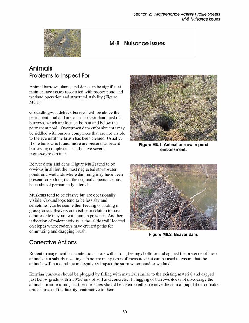
Section 2: Maintenance Activity Profile Sheets M-8 Nuisance Issues
M-8 Nuisance Issues
Animals Problems to Inspect For
Figure M8.1: Animal burrow in pond embankment.
Animal burrows, dams, and dens can be significant maintenance issues associated with proper pond and wetland operation and structural stability (Figure M8.1). Groundhog/woodchuck burrows will be above the permanent pool and are easier to spot than muskrat burrows, which are located both at and below the permanent pool. Overgrown dam embankments may be riddled with burrow complexes that are not visible to the eye until the brush has been cleared. Usually, if one burrow is found, more are present, as rodent burrowing complexes usually have several ingress/egress points. Beaver dams and dens (Figure M8.2) tend to be obvious in all but the most neglected stormwater ponds and wetlands where damming may have been present for so long that the original appearance has been almost permanently altered.
Figure M8.2: Beaver dam.
Muskrats tend to be elusive but are occasionally visible. Groundhogs tend to be less shy and sometimes can be seen either feeding or loafing in grassy areas. Beavers are visible in relation to how comfortable they are with human presence. Another indication of rodent activity is the ‘slide trail’ located on slopes where rodents have created paths for commuting and dragging brush. Corrective Actions Rodent management is a contentious issue with strong feelings both for and against the presence of these animals in a suburban setting. There are many types of measures that can be used to ensure that the animals will not continue to negatively impact the stormwater pond or wetland. Existing burrows should be plugged by filling with material similar to the existing material and capped just below grade with a 50/50 mix of soil and concrete. If plugging of burrows does not discourage the animals from returning, further measures should be taken to either remove the animal population or make critical areas of the facility unattractive to them.
50

Section 2: Maintenance Activity Profile Sheets M-8 Nuisance Issues
Management options for beaver control include complete tolerance, evaluation on a site-by-site basis, and complete removal. Beaver populations typically will only respond to trapping, dam and lodge removal, or the use of beaver “baffles”. Beavers usually do not remain in unsuitable areas. If their dams are breached and their lodges are damaged on a regular basis, the animals typically move on to another location. For instance, their lodges and dams may be removed by simple mechanical methods over two to three seasons. Once these structures are destroyed, regular maintenance of the facilities is often adequate to prevent their activity from becoming a future problem. However, maintenance staff should be prepared for the displaced animals to be persistent in their efforts to maintain their dams and lodges. Monthly site checks are recommended to ensure that dams and lodges are not rebuilt in the weeks after the initial removal. Once there is no evidence of recent beaver activity, normal less frequent maintenance usually suffices to keep the facility functioning properly. If there can be no tolerance of beaver activity, then the parties responsible for beaver control must consider relocating or trapping the unwanted animals. It is important to keep in mind that whatever features make the community appealing to one beaver will also make the area desirable to other beavers. Once one animal or family is removed, the pond or wetland will likely be re-occupied by other beavers, as young males are forced to find their own habitat areas each spring. Animal specialists perform trapping. If removal or trapping is utilized as a management tool, expect to continue trapping the area on a regular (i.e., seasonal) basis to maintain the level of control desired by the community. There are two additional points to consider concerning trapping:
Beaver relocation is much more expensive and challenging than straight trapping (killing beaver with standard beaver traps).
The existence of jurisdictions willing to accept relocated beavers is limited. The final option for minimizing the impact of beaver activity is the use of proprietary beaver baffles. The baffles do not eliminate the beaver impoundments, but are intended to minimize their size. The purpose of the baffle is to reduce the impact of rising water levels on real property (bridges, open areas, private property, pathways, etc.) by providing a manual method for changing the water level in the ponds (thus, making dam building more difficult). Waterfowl Problems to Inspect For Waterfowl damage usually takes the form of either reduced vegetative species due to overgrazing, or poor water quality due to high fecal coliform counts. Waterfowl issues usually involve the overpopulation of year-round duck (Figure M8.3) and geese populations (usually Canadian Geese, Branta canadensis). Geese and duck droppings on asphalt paths, pond side slopes, docks and cart ways are also easy aesthetic nuisances to spot.
Figure M8.3: Duck family.
51

Section 2: Maintenance Activity Profile Sheets M-8 Nuisance Issues
Corrective Actions The following actions can control waterfowl impacts:
Adding shoreline vegetation and no-mow zones. Using proprietary products for managing/discouraging waterfowl/goose populations Using trained canines to intimidate geese - Border Collies are the most common species used. Addling eggs - shaking the eggs of nesting geese to make the eggs nonviable while still allowing
the female goose to perform her breeding duties. Introducing predators such as snapping turtles.
Mosquitoes Problems to Inspect For Mosquito problems are usually brought to the attention of the maintenance authority by adjacent homeowners, or where organized mosquito control programs exist, by mosquito control or abatement districts. In some locations, the primary cause of a mosquito infestation may be a stormwater structure(s), but in other areas the primary cause may be natural or other man-made habitats. Sometimes, it will be both. Stormwater structures should be periodically checked to determine if there are excessive amounts of mosquitoes. Stormwater ponds typically will not have mosquito production problems in a central pool that’s 6-8 ft. deep, as long as it never dries out or becomes so depleted that water quality is impaired. A relatively large, deep pool helps promote and maintain aquatic predators of mosquito larvae (e.g. larvivorous fishes, dragonfly naiads, predacious diving beetles, water boatmen, backswimmers, salamander larvae). However, in some locations, even an abundance of natural predators may not be enough to control mosquito populations. A deep central pool also inhibits vegetation colonization within the pool, allowing wind to agitate the surface water, which discourages mosquito egg-laying. The primary areas of mosquito production are in the shallow aquatic bench areas that form the pond’s periphery and margins. Fluctuation in the pond’s water levels can cause isolated areas or pockets within the aquatic bench to cycle in a wet-dry-wet manner, creating conditions under which peripheral low spots, swales or potholes may become mosquito-rearing habitats. Sites like these that have fluctuating water levels (i.e. wet-dry-wet) for extended periods of time can favor the production of floodwater or temporary water mosquito species, many of which can fly long distances. Maintaining relatively high and stable water levels over the aquatic bench helps reduce floodwater mosquito populations. In many locations, however, (and for the best water quality functioning of the pond) it may be impossible to achieve or maintain such high water level stability. In some cases, thick mats of vegetation that cover aquatic and safety benches, emergent plants, submerged aquatic vegetation, or floating algae, can also promote mosquito production. Thick vegetation can inhibit access of mosquito predators to mosquito rearing sites, creating a refuge within the aquatic or safety benches where either permanent (“standing”) water mosquitoes or more ephemeral floodwater mosquitoes can develop and emerge. As such, without unduly sacrificing water quality goals, the aquatic and safety benches should not be allowed to develop excessively thick screens or layers of aquatic vegetation. In some situations, mosquito production may still be high despite these precautions. Insecticides may need to be applied in limited quantities to control mosquito larvae. Like stormwater ponds, stormwater wetlands have similar concerns and remedies with mosquito production. Of particular concern is a stormwater wetland’s smaller and possibly shallower central micro-pool, and an expanded high marsh pond periphery containing less than 6 inches of water. Even the
52

Section 2: Maintenance Activity Profile Sheets M-8 Nuisance Issues
wetland’s low marsh zone, being only 6-18 inches deep, could form problematic breeding spots during times of drought and subsequent rewetting. In some instances, limited amounts of larvicides may need to be used. Corrective Actions The most effective mosquito control program is one that eliminates potential breeding habitats. Most stagnant pools of water can be attractive to mosquitoes and the source of a large mosquito population. Ponded water such as open cans and bottles, debris and sediment accumulations, and areas of ground settlement provide ideal locations for mosquito breeding. A maintenance program dedicated to eliminating potential breeding areas is preferable to controlling flying mosquitoes. Whenever excessive mosquito production is encountered in a stormwater structure, a state, county, or local mosquito control or abatement district should be contacted to request appropriate control actions. In areas where such organized mosquito control programs do not exist, contract with a private company for control actions. Alternatively, a knowledgeable homeowner or homeowner’s association might be able to undertake some limited control actions on their own. Quite often, it might be a matter of contacting a local stormwater management agency to undertake needed or neglected maintenance activities within a stormwater structure. Organized mosquito control or abatement districts typically provide comprehensive, integrated pest management remedies for addressing excessive mosquito production, involving source reduction, larviciding and adulticiding techniques. Private companies tend to be restricted to larviciding efforts, and wherever they might attempt some source reduction remedies in a stormwater structure, they should only do so in consultation with the local stormwater management agency. Larvicide efforts target potential or actual breeding areas and treat them with insecticides that include bacterially-produced products, juvenile growth hormone mimics, and organophosphates. Adulticides that are applied to more widespread areas by aircraft or truck-mounted sprayers include organophosphates and synthetic pyrethroids and should be used only when source reduction or larviciding efforts are not working. Application of any pesticides must be in accordance with the requirements specified on the labels. Seasonal stocking of predatory fish that eat mosquito larvae is also undertaken in many areas by mosquito control or abatement districts, relying upon mosquitofish (Gambusia spp.) in warmer climates, and on the black-striped topminnow (Notrophus fundulus), in colder climates. Private companies or homeowners should not undertake fish stocking on their own without first consulting with their state fish and wildlife management agency and/or their state nongame or natural heritage programs to be sure that such fish stocking is permissible and that all pertinent regulations are followed. Undesirable Plant Communities Problems to Inspect For Diverse plant communities support diverse and balanced aquatic communities that host beneficial species such as mosquito predators. Poorly maintained ponds and wetlands are particularly susceptible to the establishment of undesirable plant communities that include monocultures and non-native invasive species. Aquatic plant species such as cattails and common reed are typical monocultures seen in ponds and wetlands, and as previously mentioned cattail stands in particular can produce the very difficult to control Coquilletidia perturbans mosquito, an aggressive biter. Similarly, side slopes and embankments are susceptible to rapid colonization by non-natives such as multiflora rose, kudzu (southeastern states), purple loosestrife, and porcelain berry.
53

Section 2: Maintenance Activity Profile Sheets M-8 Nuisance Issues
Corrective Actions Management of monolithic plant communities and weeds requires a long-term commitment to action to prevent large-scale problems. Mechanical and hand removal of monocultures such as cattails and common reed is often necessary in conjunction with replanting with other appropriate native emergent species. Algaecides and herbicides are often used to eradicate existing weed species. This method treats the problem as an ongoing maintenance issue and generally requires multiple treatments throughout the growing season. It is often the most effective method of maintaining the desired aesthetic standard for a pond. Caution should be exercised in performing chemical applications in that some applications may have the desired affect of removing unwanted vegetation, but may increase toxic risks to other resident species. The removal of one weed species creates an opportunity for the growth of another. Once the initial weed is eliminated, the ecological niche previously occupied by the species becomes available to other opportunistic species. Note that multiple applications may be necessary to maintain the desired aesthetic standard for a stormwater pond or wetland. Maintaining and/or planting upland buffer zones can help to reduce the introduction of nuisance plant species. Planting emergent vegetation may also reduce nuisance algae blooms and waterfowl access. These plants compete with the algae for the available nutrients stored in the pond substrate. As fewer nutrients are available for the algae, their prolific growth potential can be suppressed. Another vegetation management technique is through the establishment of buffer strips or “no mow areas” around the perimeter of stormwater wet ponds and wetlands. These zones help intercept and filter nutrient laden runoff as well as stabilize pond banks. Therefore a mixture of plants with varying heights is recommended. Water Quality Degradation Problems to Inspect For Stormwater ponds and wetlands are susceptible to poor water quality when upland land uses are highly urbanized, deliver large quantities of nutrients, or contain illicit discharges with high concentrations of bacteria and other pollutants. Pond and wetland designs with inefficient turn over (i.e., poor flow circulation) also contribute to water quality degradation. Common indications of poor water quality include an off color (e.g., bright green sheen from algae) or unpleasant odor (e.g., presence of bacteria). Poor water quality, including low dissolved oxygen and organic over-enrichment can also undesirably promote mosquito production by reducing mosquito predators and providing food for mosquito larvae. Corrective Actions Maintaining water quality in stormwater ponds and wetlands is challenging, as they are designed to retain constituents in stormwater that can degrade receiving waters. However, a number of water quality related fixes are noted below: • Bacterial Improvements
Excessive sediments in a pond can contribute to algae problems. If sediment layers become anaerobic, harmful chemicals, noxious odors, and phosphorus can be released into the water column. These conditions can be minimized through the introduction of bacteria in the pond. The bacteria, in the presence of adequate aeration, “digest” the muck layer without producing the harmful side effects,
54

Section 2: Maintenance Activity Profile Sheets M-8 Nuisance Issues
55
such as odor, associated with anaerobic decomposition. Through the reduction of available phosphorus, algae growth can be limited. Treatments usually start in early April and continue through September.
• Diffusers and surface aerators
Air can be introduced into the pond or wetland through various systems to facilitate biological decomposition of pond muck, de-stratify thermal layers in the water and improve the ecological health of the system. In general air promotes biological activity, which reduces the amount of available nutrients for algae.
Diffusers use an air compressor and hoses to bring air into the water column of the pond or wetland. Diffuser systems are low maintenance and are often compared to aquarium compressors on a larger scale. They require annual maintenance and are not recommended for permanent pools less than eight feet deep.
Aerators resemble fountains in their appearance. They require a motor mounted to an impeller or other type of agitator to “splash” the water. This physical action introduces air to the water. They should be removed from the pond in the late fall to prevent freeze damage and returned to the pond in the spring, after the last freeze. Trash, debris, algae, pond weeds and aquatic plants can bind up moving parts, causing excessive wear and generally cause motors to burn out prematurely. Because these aerators typically draw from the surface of the pond, they are generally not recommended for reducing algae bloom potential or increasing dissolved oxygen in the system, but may provide visual enhancement.
• Flocculants
Flocculants are chemicals applied to ponds to act indirectly on the algae through promotion of settling. The application of flocculates of buffered alum products to the water causes phosphorus and other materials suspended in the water column to settle. Removal of phosphorus from the water column limits the amount of this nutrient available to support algal growth. This works best when water clarity is greater than 24 inches. However, soils with excessive nutrients introduce phosphorous with every rain event and as a result, phosphorus levels are quickly recharged and the value of floccing the pond is minimized. The application of flocculants may require a permit. Therefore check with local authorities prior to application.
Cautions and Safety Tips Addressing nuisance issues has few associated safety hazards when appropriately trained individuals conduct the specific tasks (e.g., trapping, chemical application).
References
References Brown, Ted and Jon Simpson. 2002. “Determining the Trophic State of Your Lake.” Watershed
Protection Techniques, Volume 3 No. 4. Center for Watershed Protection. Brown, W. and T. Schueler. 1997. The Economics of Stormwater BMPs in the Mid-Atlantic Region.
Prepared for: Chesapeake Research Consortium. Edgewater, MD. Center for Watershed Protection. Ellicott City, MD.
Center for Watershed Protection. 2001. The Economic Benefits of Protecting Virginia’s Streams, Lakes,
and Wetlands and The Economic Benefits of Better Site Design in Virginia. Prepared for Virginia Department of Conservation and Recreation. Richmond, VA.
Center for Watershed Protection. Stormwater Manager’s Resource Center. On-Line at:
www.stormwatercenter.net Schueler, et al. 2007. Urban Subwatershed Restoration Manual No. 3: Urban Stormwater Retrofit
Practices. Center for Watershed Protection. Prepared for Office of Wastewater Management, USEPA. Washington, D.C.
Environmental Protection Agency. 2005a. Maryland-Delaware Stormwater Management/Mosquito
Control Workshop (Salisbury, MD., Feb. 9, 2005). Posting of PowerPoint presentations from EPA-sponsored workshop at http://www.epa.gov/maia/html/swmprog.html
Environmental Protection Agency. 2005b. National Management Measures to Control Nonpoint Source
Pollution from Urban Areas. Office of Wetlands, Oceans and Watersheds. Publication Number EPA 841-B-05-004, November 2005
Metzger, M.E. 2004. Managing Mosquitoes in Stormwater Treatment Devices. Univ. Calif ANR Publ.
8125. 11 pp. Natural Resources Conservation Service. 1987. Natural Resources Conservation Handbook.
Washington, D.C. Newman, Jonathan. 1997. “Information Sheet 3: Control of Algae with Straw.” IACR-Centre for
Aquatic Plant Management. Aquatic Systems Inc. Web Page (http://www.execpc.com/~aqsys/barley.html)
Robert L. Knight a, William E. Walton b, George F. O’Meara c, William K. Reisen d, Roland Wass e
2003, Strategies for effective mosquito control in constructed treatment wetlands Santana, F., J. Wood, R. Parsons, and S. Chamberlain. 1994. Control of Mosquito Breeding in Permitted
Stormwater Systems. For: Southwest Florida Water Management District. Brooksville, FL. Walton, W.E. 2003. Managing Mosquitoes in Surface-Flow Constructed Treatment Wetlands. Univ.
Calif. ANR Publ. 8117. 11 pp. Watershed Management Institute (WMI). 1997. Operation, Maintenance, and Management of
Stormwater Management Systems. Prepared for: US EPA Office of Water. Washington, DC.
56

References
57
Winer, Rebecca. 2000. National Pollutant Removal Performance Database. Center for Watershed Protection.

Appendix A
Appendix A:
Unit Costs for Pond and Wetland Maintenance
Stormwater Wet Pond and Wetland Management Guidebook

Stormwater Wet Pond and Wetland Management Guidebook Appendix A
TABLE A-1. UNIT COSTS FOR POND AND WETLAND MAINTENANCE1
Maintenance Item
Unit Price ($)
Unit
Mobilization
Cost ($)2
Maintenance Interval
(yrs)3 Permanent Pool Issues
Dam/ Embankment unclog internal drains for embankments
10
lf
1,500
R (10)
repair low spots in dam or berm
170
cy
1,500
R (5)
Clogging
debris removal (preventative)
350
event
0
0.25-1 clear outfall channel of sediment
130
cy
0
5-15
clogged low flow
750
event
800
0.25-1 Pipe Repairs
Structural - Riser and Barrel re-tar CMP barrel
11
sf
800
15-20
install new elbow underground
1,200
ea
800
R
repair CMP barrel joint leak
530
ea
800
R (3-5)
repair leaking concrete principal spillway joint
1,200
ea
0
R (5-10)
replace riser (CMP)
12,000
ea
>2,500
R (25)
replace riser (concrete)
20,000
ea
>2,500
R (50)
replace barrel
1,000
lf
>2,500
R (25-50)
1) These costs were largely derived from data from the Maryland region, based on bid proposal and actual 2005 project data. 2) Cost at four levels: $0 for no mobilization; $800 for minimal mobilization; $1,500 for small project mobilization; >$2,500 for large project
mobilization. Note that these are approximations. For items with no mobilization cost, it is assumed that the mobilization cost is incorporated into the overall unit cost, or that the maintenance can be completed during inspection.
3) Bottom number in range represents ideal maintenance interval. Top number represents maximum interval between maintenance activities. R indicates repair items, whose frequency is somewhat unpredictable. The frequencies sometimes reported in parentheses represent an estimate of typical repair frequency.
Page A-1
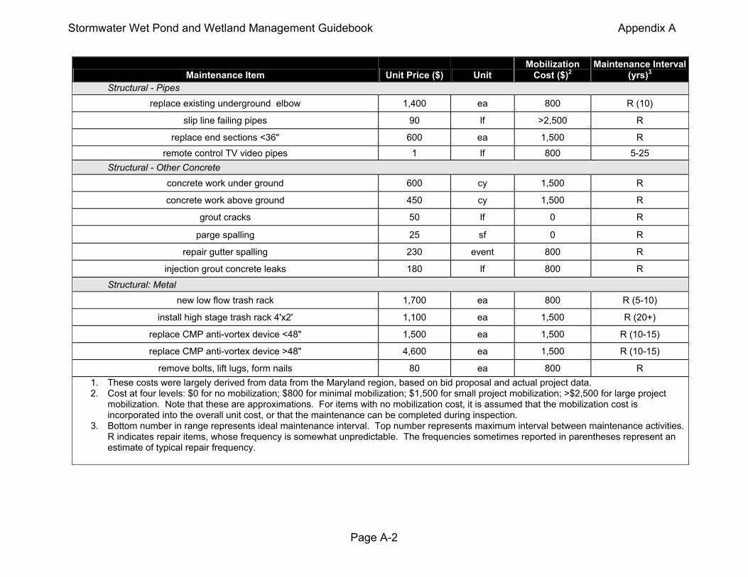
Stormwater Wet Pond and Wetland Management Guidebook Appendix A
Maintenance Item
Unit Price ($)
Unit
Mobilization
Cost ($)2
Maintenance Interval
(yrs)3 Structural - Pipes
replace existing underground elbow
1,400
ea
800
R (10)
slip line failing pipes
90
lf
>2,500
R
replace end sections <36"
600
ea
1,500
R
remote control TV video pipes
1
lf
800
5-25
Structural - Other Concrete
concrete work under ground
600
cy
1,500
R
concrete work above ground
450
cy
1,500
R
grout cracks
50
lf
0
R
parge spalling
25
sf
0
R
repair gutter spalling
230
event
800
R
injection grout concrete leaks
180
lf
800
R
Structural: Metal
new low flow trash rack
1,700
ea
800
R (5-10)
install high stage trash rack 4'x2'
1,100
ea
1,500
R (20+)
replace CMP anti-vortex device <48"
1,500
ea
1,500
R (10-15)
replace CMP anti-vortex device >48"
4,600
ea
1,500
R (10-15)
remove bolts, lift lugs, form nails
80
ea
800
R 1. These costs were largely derived from data from the Maryland region, based on bid proposal and actual project data. 2. Cost at four levels: $0 for no mobilization; $800 for minimal mobilization; $1,500 for small project mobilization; >$2,500 for large project
mobilization. Note that these are approximations. For items with no mobilization cost, it is assumed that the mobilization cost is incorporated into the overall unit cost, or that the maintenance can be completed during inspection.
3. Bottom number in range represents ideal maintenance interval. Top number represents maximum interval between maintenance activities. R indicates repair items, whose frequency is somewhat unpredictable. The frequencies sometimes reported in parentheses represent an estimate of typical repair frequency.
Page A-2

Stormwater Wet Pond and Wetland Management Guidebook Appendix A
Maintenance Item
Unit Price ($)
Unit
Mobilization
Cost ($)2
Maintenance Interval
(yrs)3
Vegetation Management sod 3.30
sy 800 1-2
seed and top soil bare areas (3 inch depth)
4.40
sy
800
1-2 plant 1.5 inch tree
84
ea
0
R3
plant shrub
15
ea
0
R
mowing
300
ac
0
0.5-1
clear outfall and channel of trees
5.50
sy
800
0.5-1 clear embankment of small trees by hand
3.30
sy
800
0.5-1
clear embankment trees with Ambusher or Brushhog
0.90
sy
800
0.5-1 remove live tree (<12 inches)
130
ea
800
R (1-10)
remove live trees larger than 12 inches, <24 inches
250
ea
800
R (10-25)
remove downed timber (up to 40 cy of material)
2,200
event
0
0.25-1
remove dumped vegetative material (up to 40 cy)
2,600
event
0
0.25-1 install wetland plant
6
ea
800
R (3-5)
remove invasive wetland vegetation (machine remove phragmites)
(up to 40 cy)
3,000
event
0
R spray for algae (0.25 ac pond) 600
ea 0 R
spray for cattails (0.25 ac pond) 330
ea 0 R repair low spots in dry pond bottom 25
sy 1,500 R
remove woody vegetation from dry pond bottom
1,700
event
0
5-10 1. These costs were largely derived from data from the Maryland region, based on bid proposal and actual project data. 2. Cost at four levels: $0 for no mobilization; $800 for minimal mobilization; $1,500 for small project mobilization; >$2,500 for large project
mobilization. Note that these are approximations. For items with no mobilization cost, it is assumed that the mobilization cost is incorporated into the overall unit cost, or that the maintenance can be completed during inspection.
3. Bottom number in range represents ideal maintenance interval. Top number represents maximum interval between maintenance activities. R indicates repair items, whose frequency is somewhat unpredictable. The frequencies sometimes reported in parentheses represent an estimate of typical repair frequency.
Page A-3

Stormwater Wet Pond and Wetland Management Guidebook Appendix A
Maintenance Item
Unit Price ($)
Unit
Mobilization
Cost ($)2
Maintenance Interval
(yrs)3 Dredging and Mucking
dredge wet ponds (jobs larger than 1000 cy) haul offsite
60
cy
>2,500
5-15 dry pond sediment removal
7,600
event
0
15-25
dewater pond
900
event
0
15-25 muck out undergrounds
390
cy
0
0.5-1
dewater and remove sludge from underground facilities
1
gal
0
0.25-1 typical sediment dump fee (not including trucking)
66
ton
0
NA
truck day for landfill to transport underground dredge materials (minimum, assume 2 to 4 trips in one day)
800
trip-day
0
NA
Access/ Safety install warning signs
210
ea
0
R
add manhole steps
100
ea
800
R
new manhole cover
250
ea
0
R
create 12' access road (permanent, cut/fill balances)
40
lf
1,500
R
create 12' access road (permanent, cut/fill non-balance)
65
lf
1,500
R
create 12' access road (temp)
12
lf
1,500
R
install chainlink fence
26
lf
800
R
install ladder (8 foot)
220
each
800
R
install three rail fence
15
lf
800
R
repair asphalt path
26
cy
800
R
supply lock and chain for first one (additional at $30 apiece)
130
ea
0
4-8 1. These costs were largely derived from data from the Maryland region, based on bid proposal and actual project data. 2. Cost at four levels: $0 for no mobilization; $800 for minimal mobilization; $1,500 for small project mobilization; >$2,500 for large project
mobilization. Note that these are approximations. For items with no mobilization cost, it is assumed that the mobilization cost is incorporated into the overall unit cost, or that the maintenance can be completed during inspection.
3. Bottom number in range represents ideal maintenance interval. Top number represents maximum interval between maintenance activities. R indicates repair items, whose frequency is somewhat unpredictable. The frequencies sometimes reported in parentheses represent an estimate of typical repair frequency.
Page A-4

Stormwater Wet Pond and Wetland Management Guidebook Appendix A
Page A-5
Maintenance Item
Unit Price ($)
Unit
Mobilization
Cost ($)2
Maintenance Interval
(yrs)3 Mechanical Components
remove old valve
300
ea
800
R (10)
install new valve (<36 inches)
4,600
ea
1,500
R
install new valve (< 24 inches)
3,100
ea
1,500
R
install new valve (<11 inches)
1,300
ea
1,500
R
install new valve (<7 inches)
460
ea
800
R
lubricate valves (same price for first four)
300
ea
0
1-2 Nuisance Issues
pond/ wetland aeration
560
ea
0
1 treat pond for mosquitoes
1,000
acre
0
R
trap beavers (one week, one location, family of 6)
1,000
event
0
R fill animal burrows
23
sy
800
R (5-10)
remove graffiti
310
day
800
1-3
Erosion/ Channel Maintenance establish new riprap pilot channels (8' wide, 1' deep)
38
lf
1,500
5-15
remove and replace rip rap or pea gravel
160
sy
1,500
15-25
shoreline protection
50
lf
1,500
R
new riprap (general)
80
cy
1,500
R (5-10)
erosion repair
1,100
event
0
R (2-5)
jet clean rip rap (6X 15, 1' silt)
2,500
event
0
15-25
4) These costs were largely derived from data from the Maryland region, based on bid proposal and actual project data. 5) Cost at four levels: $0 for no mobilization; $800 for minimal mobilization; $1,500 for small project mobilization; >$2,500 for large project
mobilization. Note that these are approximations. For items with no mobilization cost, it is assumed that the mobilization cost is incorporated into the overall unit cost, or that the maintenance can be completed during inspection.
6) Bottom number in range represents ideal maintenance interval. Top number represents maximum interval between maintenance activities. R indicates repair items, whose frequency is somewhat unpredictable. The frequencies sometimes reported in parentheses represent an estimate of typical repair frequency.
Appendix B
Appendix B:
Pond and Wetland Checklists
Stormwater Wet Pond and Wetland Management Guidebook

Adapted from WMI, 1997 Page 1 of 5
STORMWATER POND / STORMWATER WETLAND CONSTRUCTION INSPECTION CHECKLIST
Date: Time:
Project:
Location:
Site Status (active, inactive, completed):
Inspector(s):
Type of Practice:
G Micropool ED Pond G Shallow Wetland
G Wet Pond G Shallow ED Wetland
G Multiple Pond System G Pond / Wetland System
G Pocket Pond G Pocket Wetland
Construction Sequence Satisfactory Unsatisfactory Comments
I. Pre-Construction / Materials and Equipment
Pre-construction meeting
Pipe and appurtenances on-site prior to constructionand dimensions checked
1. Material (including protective coating, if specified)
2. Diameter
3. Dimensions of metal or pre-cast concrete riser
4. Required dimensions between water controlstructures (orifices, weirs, etc.) are in accordancewith approved plans
5. Barrel stub for prefabricated pipe structures atproper angle for design barrel slope
6. Number and dimensions of prefabricated anti-seepcollars
7. Watertight connectors and gaskets
8. Outlet drain valve
Project benchmark near pond site
Equipment for temporary de-watering / sediment anderosion control
II. Subgrade Preparation
Area beneath embankment stripped of all vegetation,topsoil, and organic matter
Core trench excavated and backfilled
III. Pipe Spillway Installation
Method of installation detailed on plans
A. Bed preparation
Installation trench excavated with specified sideslopes
Stable, uniform, dry subgrade of relativelyimpervious material (If subgrade is wet, contractorshall have defined steps before proceeding withinstallation)
Invert at proper elevation and grade

STORMWATER POND / STORMWATER WETLAND CONSTRUCTION INSPECTION CHECKLIST
Construction Sequence Satisfactory Unsatisfactory Comments
Adapted from WMI, 1997 Page 2 of 5
B. Pipe placement
Metal / plastic pipe
1. Watertight connectors and gaskets properlyinstalled
2. Anti-seep collars properly spaced and havingwatertight connections to pipe
3. Backfill placed and tamped by hand under“haunches” of pipe
4. Remaining backfill placed in max. 8 inch liftsusing small power tamping equipment until 2 feetcover over pipe is reached
Concrete pipe
1. Pipe set on blocks or concrete slab for pouring oflow cradle
2. Pipe installed with rubber gasket joints with nospalling in gasket interface area
3. Excavation for lower half of anti-seep collar(s)with reinforcing steel set
4. Entire area where anti-seep collar(s) will come incontact with pipe coated with mastic or otherapproved waterproof sealant
5. Low cradle and bottom half of anti-seep collarinstalled as monolithic pour and of an approvedmix
6. Upper half of anti-seep collar(s) formed withreinforcing steel set
7. Concrete for collar of an approved mix andvibrated into place (protected from freezing whilecuring, if necessary)
8. Forms stripped and collar inspected forhoneycomb prior to backfilling. Parge ifnecessary.
C. Backfilling
Fill placed in maximum 8 inch lifts
Backfill taken minimum 2 feet above top of anti-seepcollar elevation before traversing with heavyequipment
IV. Riser / Outlet Structure Installation
Riser located within embankment
A. Metal riser
Riser base excavated or formed on stable subgradeto design dimensions
Set on blocks to design elevations and plumbed
Reinforcing bars placed at right angles andprojecting into sides of riser
Concrete poured so as to fill inside of riser to invertof barrel
B. Pre-cast concrete structure
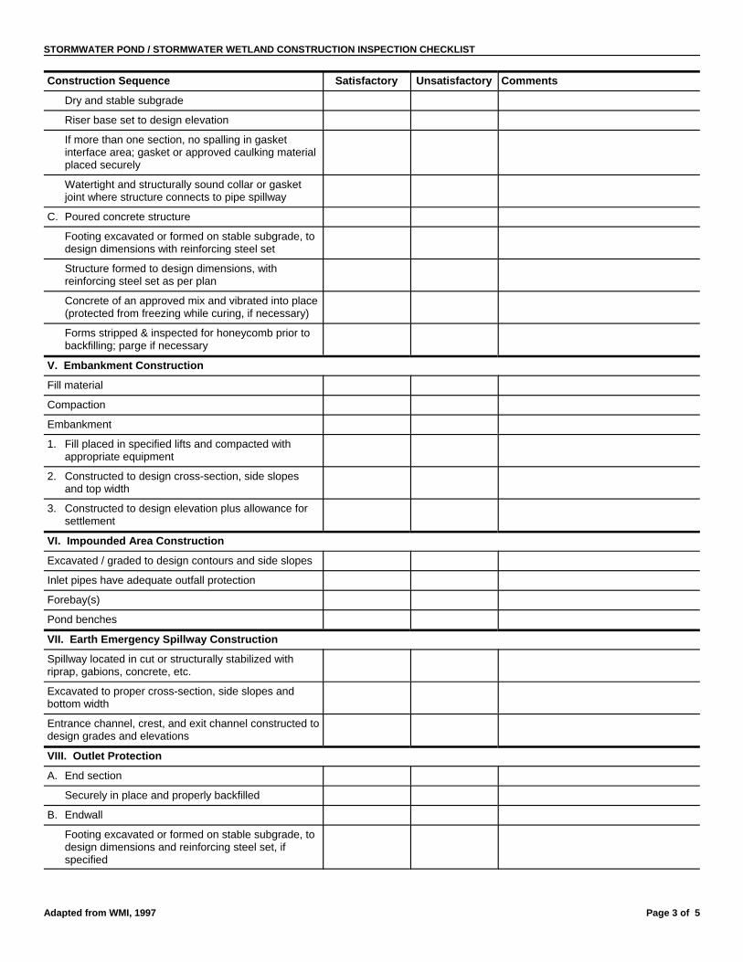
STORMWATER POND / STORMWATER WETLAND CONSTRUCTION INSPECTION CHECKLIST
Construction Sequence Satisfactory Unsatisfactory Comments
Adapted from WMI, 1997 Page 3 of 5
Dry and stable subgrade
Riser base set to design elevation
If more than one section, no spalling in gasketinterface area; gasket or approved caulking materialplaced securely
Watertight and structurally sound collar or gasketjoint where structure connects to pipe spillway
C. Poured concrete structure
Footing excavated or formed on stable subgrade, todesign dimensions with reinforcing steel set
Structure formed to design dimensions, withreinforcing steel set as per plan
Concrete of an approved mix and vibrated into place(protected from freezing while curing, if necessary)
Forms stripped & inspected for honeycomb prior tobackfilling; parge if necessary
V. Embankment Construction
Fill material
Compaction
Embankment
1. Fill placed in specified lifts and compacted withappropriate equipment
2. Constructed to design cross-section, side slopesand top width
3. Constructed to design elevation plus allowance forsettlement
VI. Impounded Area Construction
Excavated / graded to design contours and side slopes
Inlet pipes have adequate outfall protection
Forebay(s)
Pond benches
VII. Earth Emergency Spillway Construction
Spillway located in cut or structurally stabilized withriprap, gabions, concrete, etc.
Excavated to proper cross-section, side slopes andbottom width
Entrance channel, crest, and exit channel constructed todesign grades and elevations
VIII. Outlet Protection
A. End section
Securely in place and properly backfilled
B. Endwall
Footing excavated or formed on stable subgrade, todesign dimensions and reinforcing steel set, ifspecified

STORMWATER POND / STORMWATER WETLAND CONSTRUCTION INSPECTION CHECKLIST
Construction Sequence Satisfactory Unsatisfactory Comments
Adapted from WMI, 1997 Page 4 of 5
Endwall formed to design dimensions withreinforcing steel set as per plan
Concrete of an approved mix and vibrated into place(protected from freezing, if necessary)
Forms stripped and structure inspected forhoneycomb prior to backfilling; parge if necessary
C. Riprap apron / channel
Apron / channel excavated to design cross-sectionwith proper transition to existing ground
Filter fabric in place
Stone sized as per plan and uniformly place at thethickness specified
IX. Vegetative Stabilization
Approved seed mixture or sod
Proper surface preparation and required soilamendments
Excelsior mat or other stabilization, as per plan
X. Miscellaneous
Drain for ponds having a permanent pool
Trash rack / anti-vortex device secured to outletstructure
Trash protection for low flow pipes, orifices, etc.
Fencing (when required)
Access road
Set aside for clean-out maintenance

STORMWATER POND / STORMWATER WETLAND CONSTRUCTION INSPECTION CHECKLIST
Adapted from WMI, 1997 Page 5 of 5
Additional Comments:
Action to be Taken:
No action necessary. Continue routine inspections.
Correct noted site deficiencies by
1st notice
2nd notice
Submit plan modifications as noted in written comments by
Notice to Comply issued
Final inspection, project completed

N/A = Not Applicable 1 = Monitor for Future RepairsN/I = Not Investigated 2 = Routine Repairs Needed0 = Not a Problem 3 = Immediate Repair Needed Page 1 of 6
POND / WETLAND MAINTENANCE INSPECTION FORM
Facility Number: Date: Time:
Subdivision Name: Watershed:
Weather: Inspector(s):
Date of Last Rainfall: Amount: Inches Streets:
Mapbook Location: GPS Coordinates:
Property Classification: Residential 9 Government 9 Commercial 9 Other:
Type of Practice: Wet Pond 9 Dry Pond 9 Micropool ED 9 Multiple Pond System 9 Pocket Pond 9
Shallow Wetland 9 Shallow ED 9 Pond/ Wetland 9 Pocket Wetland 9
Confined 9 Unconfined 9 Barrel Size As-built Plan Available? Yes 9 No 9
Is Facility Inspectable? Yes 9 No 9 Why? Comments Specific Location(s):
Scoring Breakdown:
N/A = Not Applicable 1 = Monitor (potential for future problem exists) * Use open space in each section tofurther explain scoring as needed
N/I = Not Investigated 2 = Routine Maintenance Required
0 = Not a Problem 3 = Immediate Repair Necessary
1. Outfall Channel(s) from Pond
Woody growth within 5’ of outfall barrel N/A N/I 0 1 2 3
Outfall channel functioning N/A N/I 0 1 2 3
Manholes, Frames and Covers N/A N/I 0 1 2 3
Released water undercutting outlet N/A N/I 0 1 2 3
Erosion N/A N/I 0 1 2 3
Displaced rip rap N/A N/I 0 1 2 3
Excessive sediment deposits N/A N/I 0 1 2 3
Other: N/A N/I 0 1 2 3
2. Downstream Dam Bank
Cracking, bulging, or sloughing of dam N/A N/I 0 1 2 3
Erosion and/or loss of dam material N/A N/I 0 1 2 3
Animal burrows N/A N/I 0 1 2 3
Soft spots or boggy areas N/A N/I 0 1 2 3
Woody growth or unauthorized plantings on dam N/A N/I 0 1 2 3
Other: N/A N/I 0 1 2 3
3. Upstream Dam Bank
Cracking, bulging, or sloughing of dam N/A N/I 0 1 2 3
Erosion and/or loss of dam material N/A N/I 0 1 2 3
Animal Burrows N/A N/I 0 1 2 3
Soft spots or boggy areas N/A N/I 0 1 2 3
Woody growth or unauthorized plantings on dam N/A N/I 0 1 2 3
Other: N/A N/I 0 1 2 3

POND / WETLAND MAINTENANCE INSPECTION FORM
N/A = Not Applicable 1 = Monitor for Future RepairsN/I = Not Investigated 2 = Routine Repairs Needed0 = Not a Problem 3 = Immediate Repair Needed Page 2 of 6
4. Emergency Spillway
Woody growth or unauthorized plantings N/A N/I 0 1 2 3
Erosion or back cutting N/A N/I 0 1 2 3
Soft or boggy areas N/A N/I 0 1 2 3
Obstructions / debris N/A N/I 0 1 2 3
5. Principal Spillway Built to Plans
# of Barrels: Size: RCP CMP PVC STEEL or MASONRY (Circle One)
Confined space entry permit required for entry into all riser and barrels Entry Approved 9 Entry Denied 9
Minor spalling or parging (<1”) N/A N/I 0 1 2 3
Major spalling (exposed rebar) N/A N/I 0 1 2 3
Joint failure N/A N/I 0 1 2 3
Loss of joint material N/A N/I 0 1 2 3
Leaking N/A N/I 0 1 2 3
Corrosion N/A N/I 0 1 2 3
Protective material deficient N/A N/I 0 1 2 3
Misalignment or split seams / joints N/A N/I 0 1 2 3
Other: N/A N/I 0 1 2 3
6. Riser Built to Plans
Size: CONC CMP or MASONRY (Circle One)
Minor spalling or parging (<1”) N/A N/I 0 1 2 3
Major spalling (exposed rebar) N/A N/I 0 1 2 3
Joint failure N/A N/I 0 1 2 3
Loss of joint material N/A N/I 0 1 2 3
Leaking N/A N/I 0 1 2 3
Manhole access and steps acceptable N/A N/I 0 1 2 3
Corrosion N/A N/I 0 1 2 3
Protective material deficient N/A N/I 0 1 2 3
Misalignment or split seams / joints N/A N/I 0 1 2 3
Anti-vortex device secure / acceptable N/A N/I 0 1 2 3
Sediment Accumulation within riser N/A N/I 0 1 2 3
Woody or vegetative growth within 25’ of riser N/A N/I 0 1 2 3
Safety Rebar/pipes in place N/A N/I 0 1 2 3
Safety Rebar/pipes corroded N/A N/I 0 1 2 3
Other: N/A N/I 0 1 2 3
7. Low Flow Built to Plans
Orifice and/or trash rack obstructed N/A N/I 0 1 2 3
Trash Rack Corrosion N/A N/I 0 1 2 3
Other: N/A N/I 0 1 2 3
8. Weir Trash Rack
Structurally sound N/A N/I 0 1 2 3
Debris removal necessary N/A N/I 0 1 2 3
Corrosion N/A N/I 0 1 2 3
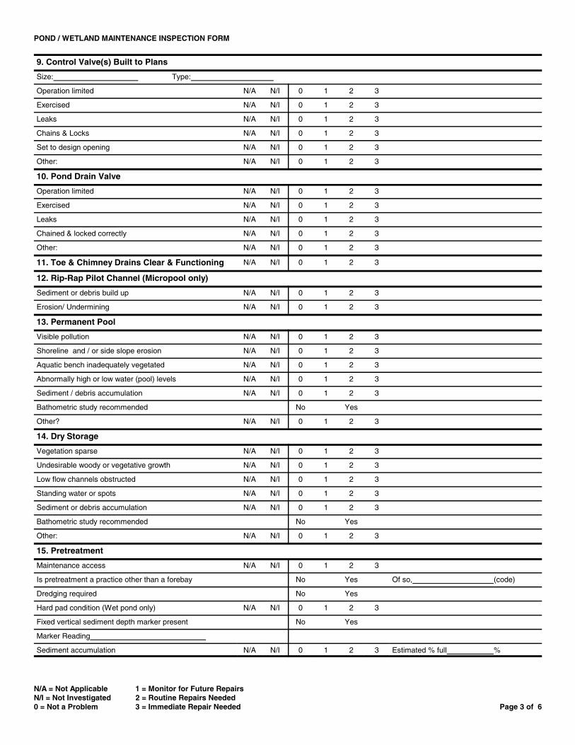
POND / WETLAND MAINTENANCE INSPECTION FORM
N/A = Not Applicable 1 = Monitor for Future RepairsN/I = Not Investigated 2 = Routine Repairs Needed0 = Not a Problem 3 = Immediate Repair Needed Page 3 of 6
9. Control Valve(s) Built to Plans
Size: Type:
Operation limited N/A N/I 0 1 2 3
Exercised N/A N/I 0 1 2 3
Leaks N/A N/I 0 1 2 3
Chains & Locks N/A N/I 0 1 2 3
Set to design opening N/A N/I 0 1 2 3
Other: N/A N/I 0 1 2 3
10. Pond Drain Valve
Operation limited N/A N/I 0 1 2 3
Exercised N/A N/I 0 1 2 3
Leaks N/A N/I 0 1 2 3
Chained & locked correctly N/A N/I 0 1 2 3
Other: N/A N/I 0 1 2 3
11. Toe & Chimney Drains Clear & Functioning N/A N/I 0 1 2 3
12. Rip-Rap Pilot Channel (Micropool only)
Sediment or debris build up N/A N/I 0 1 2 3
Erosion/ Undermining N/A N/I 0 1 2 3
13. Permanent Pool
Visible pollution N/A N/I 0 1 2 3
Shoreline and / or side slope erosion N/A N/I 0 1 2 3
Aquatic bench inadequately vegetated N/A N/I 0 1 2 3
Abnormally high or low water (pool) levels N/A N/I 0 1 2 3
Sediment / debris accumulation N/A N/I 0 1 2 3
Bathometric study recommended No Yes
Other? N/A N/I 0 1 2 3
14. Dry Storage
Vegetation sparse N/A N/I 0 1 2 3
Undesirable woody or vegetative growth N/A N/I 0 1 2 3
Low flow channels obstructed N/A N/I 0 1 2 3
Standing water or spots N/A N/I 0 1 2 3
Sediment or debris accumulation N/A N/I 0 1 2 3
Bathometric study recommended No Yes
Other: N/A N/I 0 1 2 3
15. Pretreatment
Maintenance access N/A N/I 0 1 2 3
Is pretreatment a practice other than a forebay No Yes Of so, (code)
Dredging required No Yes
Hard pad condition (Wet pond only) N/A N/I 0 1 2 3
Fixed vertical sediment depth marker present No Yes
Marker Reading
Sediment accumulation N/A N/I 0 1 2 3 Estimated % full %
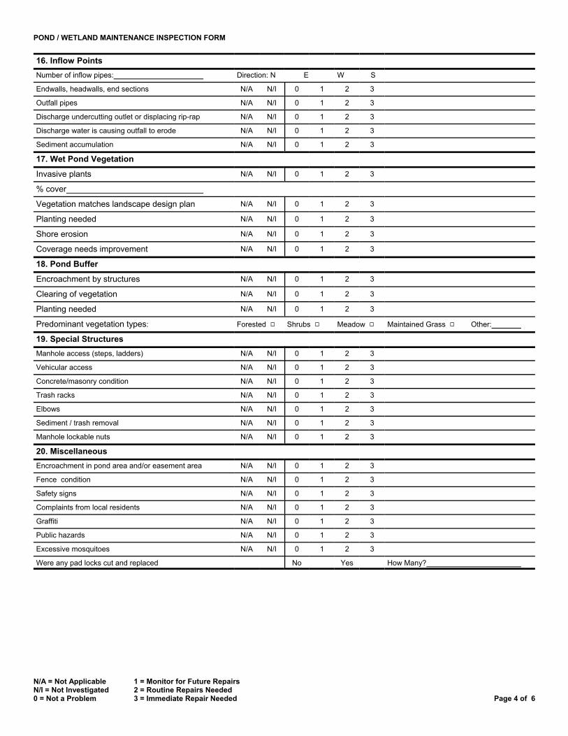
POND / WETLAND MAINTENANCE INSPECTION FORM
16. Inflow Points Number of inflow pipes: Direction: N E W S
Endwalls, headwalls, end sections N/A N/I 0 1 2 3
Outfall pipes N/A N/I 0 1 2 3
Discharge undercutting outlet or displacing rip-rap N/A N/I 0 1 2 3
Discharge water is causing outfall to erode N/A N/I 0 1 2 3
Sediment accumulation N/A N/I 0 1 2 3
17. Wet Pond Vegetation
0 1 2 3Invasive plants N/A N/I
% cover
Vegetation matches landscape design plan N/A N/I 0 1 2 3
Planting needed N/A N/I 0 1 2 3
Shore erosion N/A N/I 0 1 2 3
Coverage needs improvement N/A N/I 0 1 2 3
18. Pond Buffer
Encroachment by structures N/A N/I 0 1 2 3
Clearing of vegetation N/A N/I 0 1 2 3
Planting needed N/A N/I 0 1 2 3
Predominant vegetation types: Forested 9 Shrubs 9 Meadow 9 Maintained Grass 9 Other:
19. Special Structures Manhole access (steps, ladders) N/A N/I 0 1 2 3
Vehicular access N/A N/I 0 1 2 3
Concrete/masonry condition N/A N/I 0 1 2 3
Trash racks N/A N/I 0 1 2 3
Elbows N/A N/I 0 1 2 3
Sediment / trash removal N/A N/I 0 1 2 3
Manhole lockable nuts N/A N/I 0 1 2 3
20. Miscellaneous Encroachment in pond area and/or easement area N/A N/I 0 1 2 3
Fence condition N/A N/I 0 1 2 3
Safety signs N/A N/I 0 1 2 3
Complaints from local residents N/A N/I 0 1 2 3
Graffiti N/A N/I 0 1 2 3
Public hazards N/A N/I 0 1 2 3
Excessive mosquitoes N/A N/I 0 1 2 3
Were any pad locks cut and replaced No Yes How Many?
N/A = Not Applicable N/I = Not Investigated 0 = Not a Problem
1 = Monitor for Future Repairs 2 = Routine Repairs Needed 3 = Immediate Repair Needed Page 4 of 6
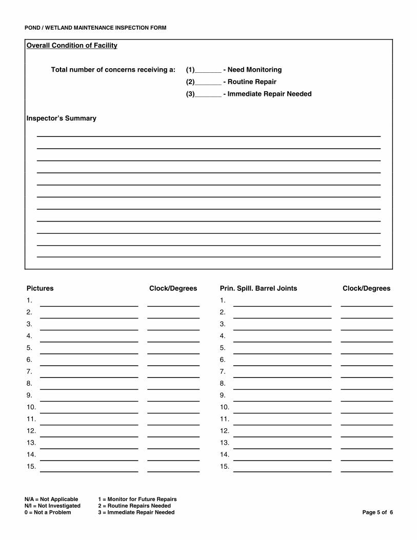
POND / WETLAND MAINTENANCE INSPECTION FORM
N/A = Not Applicable 1 = Monitor for Future RepairsN/I = Not Investigated 2 = Routine Repairs Needed0 = Not a Problem 3 = Immediate Repair Needed Page 5 of 6
Overall Condition of Facility
Total number of concerns receiving a: (1)_______ - Need Monitoring
(2)_______ - Routine Repair
(3)_______ - Immediate Repair Needed
Inspector’s Summary
Pictures Clock/Degrees Prin. Spill. Barrel Joints Clock/Degrees
1. 1.
2. 2.
3. 3.
4. 4.
5. 5.
6. 6.
7. 7.
8. 8.
9. 9.
10. 10.
11. 11.
12. 12.
13. 13.
14. 14.
15. 15.

POND / WETLAND MAINTENANCE INSPECTION FORM
N/A = Not Applicable 1 = Monitor for Future RepairsN/I = Not Investigated 2 = Routine Repairs Needed0 = Not a Problem 3 = Immediate Repair Needed Page 6 of 6
Sketches, If Necessary:

Home Owner Pond Inspection Checklist
We encourage you to copy this checklist and maintain record of your inspections. (Adapted from Hampton Roads: A Guide for Maintaining and Operating BMPs.) Answering YES to any of these questions indicates a need for corrective action or consultation with a professional inspector.
Date:______________ Inspected by:______________________________________
What to look for . . . Yes No
° Does the facility show signs of settling, cracking, bulging, misalignment or other ‘ ‘ structural deterioration?
° Do the embankments, emergency spillways, side slopes or inlet/outlet structures show ‘ ‘ signs of erosion?
° Are the pipes going into and/or out of the pond clogged or obstructed? ‘ ‘
° Do the impoundment and inlet areas show erosion, low spots or lack of stabilization? ‘ ‘
° Are there trees present on the banks? ‘ ‘
° Is there evidence of animal burrows? ‘ ‘
° Are contributing areas unstabilized with evidence or erosion? ‘ ‘
° Do vegetated areas need mowing or is there a build up of clippings that could clog the ‘ ‘ facility?
° Does sedimentation greatly decrease the BMPs capacity to hold water within the ‘ ‘ structure?
° Is there standing water in appropriate or inappropriate areas? ‘ ‘
° Is there accumulation of trash or debris? ‘ ‘
° Is there evidence of encroachment or improper use of the impounded areas? ‘ ‘
° Are there signs of vandalism? ‘ ‘
° Do any safety devices such as fences, gates or locks need repair? ‘ ‘
° Is there excessive algae or dominance of one type of vegetation? ‘ ‘
° Is there evidence of automotive fluids entering or clogging the facility? ‘ ‘
° Is there evidence of a fish kill? ‘ ‘
° Do you see a lot of mosquito larvae (small “wigglers” or “tumblers”) in the water? ‘ ‘
° Is there evidence of excessive amounts of mosquitoes? ‘ ‘
Additional Observations: