STI Operational Manual - avt-nbg.de Software Description.pdf · l MUX ØWill be indicated and...
92
Software STI SERVICE MULTIPLEXER SERVICE CONTROLLER Operational Manual
Transcript of STI Operational Manual - avt-nbg.de Software Description.pdf · l MUX ØWill be indicated and...

So
ftware
ST
IS
ER
VIC
E M
UL
TIP
LE
XE
R
SE
RV
ICE
CO
NT
RO
LL
ER
Operational M
anual

ST
I Service M
ultip
lexerS
TI S
ervice Co
ntro
ller
SO
FT
WA
RE
DE
SC
RIP
TIO
N

A P
ublication of:
AV
T A
udio Video T
echnologies Gm
bH
Rathsbergstrasse 17
D-90411 N
uernbergT
elephone +49-911-5271-0
Telefax +
49-911-5271-100
http://ww
w.avt-nbg.de
Em
ail: [email protected]
Printed in G
ermany, January 2001
A
VT
Audio V
ideo Technologies G
mbH
2001
All rights are reserved. R
eproduction in whole or in parts is
prohibited without the w
ritten consent of the copyright owner.
The inform
ation contained in this publication is accurate to the bestof our know
ledge. How
ever, we disclaim
any liability resulting fromthe use of this inform
ation and reserve the right to make changes
without notice.
Version
1.0

CO
NT
EN
T1H
ardw
are Installatio
n1 - 7
2S
oftw
are Installatio
n8 - 17
3B
asic Co
nfig
uratio
n18 - 27
4M
ain M
anag
er28 - 35
5C
on
figu
ring
of an
Au
dio
Stream
36 - 42
6G
eneratio
n o
f anM
CI o
ver CF
M43 - 55
7R
e-Co
nfig
uratio
n56 - 60
8S
etting
up
a FIG
File
61 - 77
9In
sertion
of S
TI-D
78 - 80
10A
larm an
d E
rror D
etection
81 - 85
11R
edu
nd
ancy
86 - 93
12M
on
itorin
g S
ystems
94 - 95
132-M
bit/s M
ultip
lexers96
14 P
AD
Inserter
97
15M
ultim
edia D
ata Server
98
16 S
up
po
rt99

1 © AVT GmbH
InstallationInstallationInstallationInstallation
The following 5 pages of this document describe theinstallation of MAGIC DAB Systems.
2 © AVT GmbH
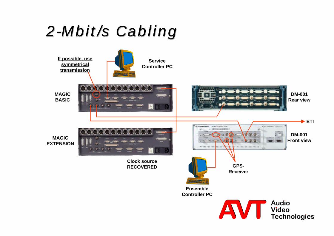
2-Mbit/s Cabling2-Mbit/s Cabling2-Mbit/s Cabling2-Mbit/s Cabling
ETI
MAGICBASIC
MAGICEXTENSION
DM-001Rear view
DM-001Front view
If possible, usesymmetricaltransmission
ServiceController PC
EnsembleController PC
GPS-Receiver
Clock sourceRECOVERED
3 © AVT GmbH
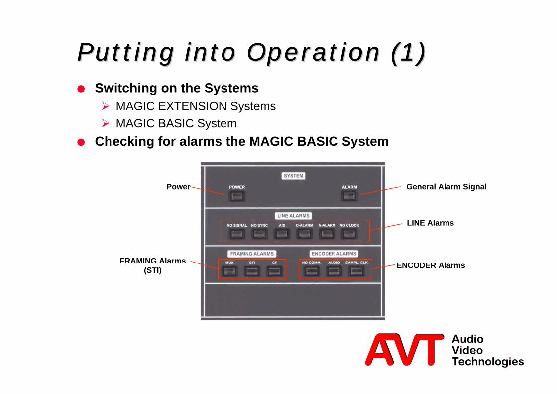
Putting into OperationPutting into OperationPutting into OperationPutting into Operation (1) (1) (1) (1)l Switching on the SystemsØ MAGIC EXTENSION SystemsØ MAGIC BASIC System
l Checking for alarms the MAGIC BASIC System
LINE Alarms
ENCODER AlarmsFRAMING Alarms(STI)
Power General Alarm Signal

4 © AVT GmbH
Putting into Operation (2)Putting into Operation (2)Putting into Operation (2)Putting into Operation (2)LINE Alarms: is the physical connection to EMUX correct?l NO SIGNALØ No 2-Mbit/s Signal (STI-C) is detected
l NO SYNCØ The 2-Mbit-Signal is present, but no framing is detected
l AISØ Alarm Indication Signal is being received from the adjacent 2-Mbit/s
Multiplexer
l D-ALARMØ Bit error rate ò10e-03: No transmission possible
l N-ALARMØ Bit error rate ò 10e-06: Should clear after 4 minutes
l NO CLOCKØ External clock not present or faulty (only if external source clock is selected)

5 © AVT GmbH
Putting into operation (3)Putting into operation (3)Putting into operation (3)Putting into operation (3)Checking for Framing Alarms:l MUXØ Will be indicated and cleared by the STI Software. Indicates, that the File
Manager is unable to establish a connection to the Ensemble-Multiplexer. Isalso displayed if the PC Software is not running.
l STIØ STI framing error in the bitstream of the STI-D Data source connected to the
LSD or HSD interface. When the interfaces are deactivated no error signalwill be indicated.
l CFØ Error in the STI back channel signal. STI framing not found.

6 © AVT GmbH
Putting into operation (4)Putting into operation (4)Putting into operation (4)Putting into operation (4)Checking for ENCODER Alarms:l NO COMMunication (collected alarm of all Encoders)Ø The Service Multiplexer Board polls all Encoder Boards found in the System.
If this alarm persists, one or more Encoder is faulty. Short duration indicationis possible.
l AUDIO (collected alarm of all Encoders)Ø The Service Multiplexer monitors the ISO/MPEG framing of all Encoders in
the System. An alarm is displayed when a missing frame is detected or faulty.
l SAMPLing CLocK (collected alarm of all Encoders)
Ø The accuracy of the incoming 2-Mbit/s clock is insufficient to the 48-kHzsampling clock of the Encoder boards.

8 © AVT GmbH
Service ControllerService ControllerService ControllerService ControllerSoftwareSoftwareSoftwareSoftware
This chapter describes the control of the MAGIC DABSystem with a Service Controller PC.

9 © AVT GmbH
Software Installation (1)Software Installation (1)Software Installation (1)Software Installation (1)l PC Hardware Requirements
Ø IBM PC AT, IBM PS/2 or 100% compatible
Ø Pentium Processor (>133 MHz) recommended
Ø Windows NT 4.0 with Service Pack 4.0 or higher
Ø approx.. 600-kByte free operating memory
Ø 20 MB free Hard Disc space
Ø IBM SVGA video card with 1024 x 768 resolution
Ø CD-ROM drive
Ø Minimum one free serial port RS-232
Ø For redundant working a second RS232 port is necessary
Ø Microsoft, IBM PS/2 or 100% software compatible Mouse
10 © AVT GmbH
Software Installation (2)Software Installation (2)Software Installation (2)Software Installation (2)l Connect the MAGIC BASIC to the RS232 port on the PC.
l Select SETUP on the delivered CD to install the program, than followthe onscreen instruction
l Important:Ø If a previous version of the STI Software is installed, this should be removed
before loading the new software.

11 © AVT GmbH
Software Installation (3)Software Installation (3)Software Installation (3)Software Installation (3)l Entering the licence number (Submenu Administration)Ø A STI licence password supplied with each MAGIC BASIC DAB SystemØ This password is only valid for the MAGIC System with the displayed serial
number of the Service Multiplexer board
Activated Features:? STI Basic Function? STI-D Inputs
12 © AVT GmbH
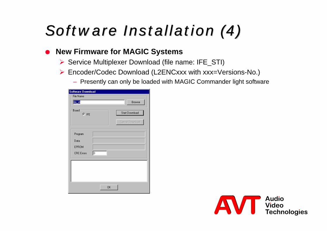
Software Installation (4)Software Installation (4)Software Installation (4)Software Installation (4)l New Firmware for MAGIC SystemsØ Service Multiplexer Download (file name: IFE_STI)Ø Encoder/Codec Download (L2ENCxxx with xxx=Versions-No.)
– Presently can only be loaded with MAGIC Commander light software

13 © AVT GmbH
Software Overview (1)Software Overview (1)Software Overview (1)Software Overview (1)
Service-Controller
PC
STI
Lineinterface:2 Mbit/s
ISDNX.21
STI Dataor
PM Data
UserInput
Control+
Control File
Conditional.FIGs
Audio+
PAD
MAGIC BASIC
DAB-Encoder
DAB-Encoder
STI-Multiplexer +Line interfaces
FIG Fast Information GroupsSTI Service Transport InterfacePM Packet ModePAD Program Associated DataCF Control File
Configuration-Data Base
Configuration-Manager
Scheduler
MAGICConfigu-
ration
CFManager
FIGEncoder
Service Multiplexer Interface (RS232C)
Control File
Main Manager
Control FIG Stream
Conditional FIGs
ServiceProviderProfile

14 © AVT GmbH
Software Overview (2)Software Overview (2)Software Overview (2)Software Overview (2)l Software ModuleØ Main Manager
– Configuration and monitoring of the System, „Main Program of the Software“
Ø Control File Manager– Module for generating and evaluating the STI-C channel to and from the Ensemble
Multiplexer
Ø FIG Encoder– Editor for generating FIG-Files (Fast Information Groups)
Ø Scheduler– Simple program flow control for reconfiguration
Ø (STI Firmware consisting of Service Multiplexer and Encoder Firmware)

15 © AVT GmbH
Software Overview (3)Software Overview (3)Software Overview (3)Software Overview (3)l For the basic configuration of the system it is necessary to enter the
Service Provider Profile (SPP) into the Ensemble-Multiplexer.Ø All necessary information about the number of possible Streams, FIG Files,
max. Data Rate etc. is in the SPP.
Ø The Service Provider can only operate within the limits of this configuration.Ø After connection set up the SPP will be exchanged between Service
Multiplexer and Ensemble Multiplexer.Ø To be able to set up a connection the Service Provider must have the
following information available:– Ensemble Multiplexer ID– Service Provider ID– Time slots to be used

16 © AVT GmbH
Software OverviewSoftware OverviewSoftware OverviewSoftware Overview (4) (4) (4) (4)l The STI Service Controller Software is implemented in accordance
with the STI Standard.Ø A complete description of all DAB features which are implemented in the STI
Software can be found in the DAB standard documentation.
l Important Standards and Documents:Ø ETSI 300 401: Radio Broadcasting Systems; Digital Audio Broadcasting
(DAB) to mobile, portable and fixed receiversØ EN 300 797: Digital Audio Broadcasting (DAB); Distribution interfaces;
Service Transport Interface (STI)Ø TR 101 496-1/2/3: DAB System: Guidelines and Rules for Implementation
and Operation Volume 1-3Ø List of all DAB Documents under (downloadable as PDF files)
http://www.eurekadab.org/Standards.htm

18 © AVT GmbH
BASIC ConfigurationBASIC ConfigurationBASIC ConfigurationBASIC Configuration (1) (1) (1) (1)COM SETTINGSl First start the Software by clicking on the icon
Main Manager Initial Configuration
l Selection of the COM port and the Baud ratel For optional redundant operation activate the Redundancy Mode
and configure the second COM port.
19 © AVT GmbH
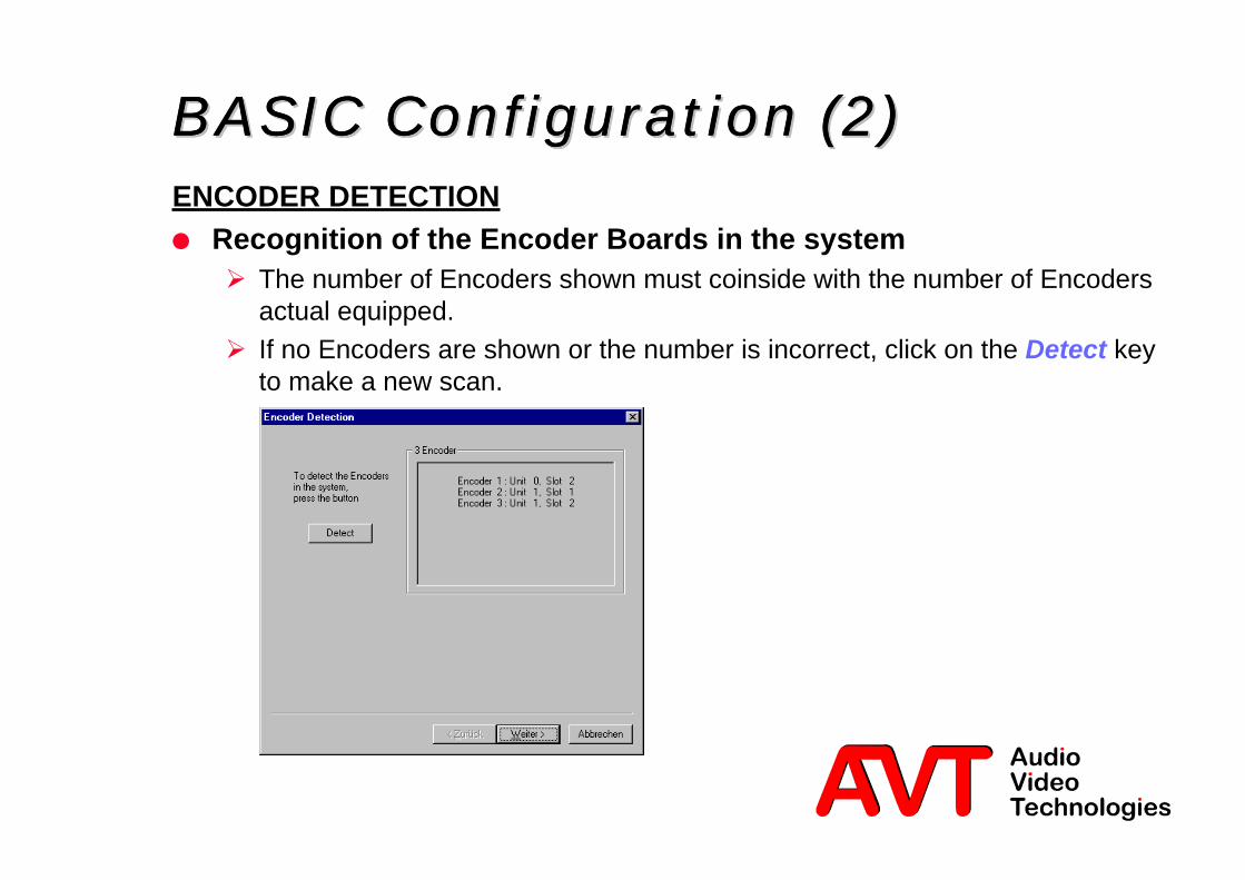
BASIC ConfigurationBASIC ConfigurationBASIC ConfigurationBASIC Configuration (2) (2) (2) (2)ENCODER DETECTIONl Recognition of the Encoder Boards in the systemØ The number of Encoders shown must coinside with the number of Encoders
actual equipped.Ø If no Encoders are shown or the number is incorrect, click on the Detect key
to make a new scan.
20 © AVT GmbH
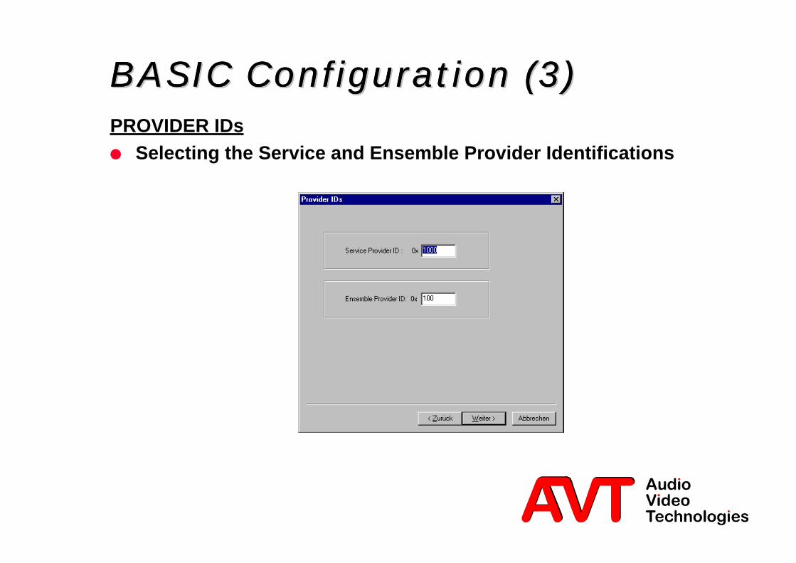
BASIC ConfigurationBASIC ConfigurationBASIC ConfigurationBASIC Configuration (3) (3) (3) (3)PROVIDER IDsl Selecting the Service and Ensemble Provider Identifications

21 © AVT GmbH
BASIC ConfigurationBASIC ConfigurationBASIC ConfigurationBASIC Configuration (4) (4) (4) (4)STI OUTPUTl Configuration of the network interface and the time slot allocation in
the transmit direction to the Ensemble Multiplexer
Must correspond with thetime slot allocation in the
EMUX
Format depends on thetransmission network

22 © AVT GmbH
BASIC Configuration (5)BASIC Configuration (5)BASIC Configuration (5)BASIC Configuration (5)STI INPUTSl Configuration of the STI-C back channell Configuration of the external STI-D data sources (MMDS, SI-MUX)
STI-C back channel can be inany of the 2-Mbit/s timeslots!
23 © AVT GmbH
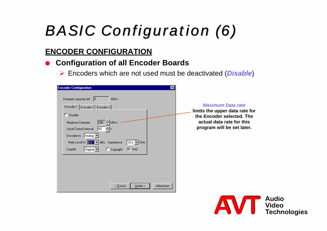
BASIC ConfigurationBASIC ConfigurationBASIC ConfigurationBASIC Configuration (6) (6) (6) (6)ENCODER CONFIGURATIONl Configuration of all Encoder BoardsØ Encoders which are not used must be deactivated (Disable)
Maximum Data ratelimits the upper data rate for
the Encoder selected. Theactual data rate for this
program will be set later.
24 © AVT GmbH
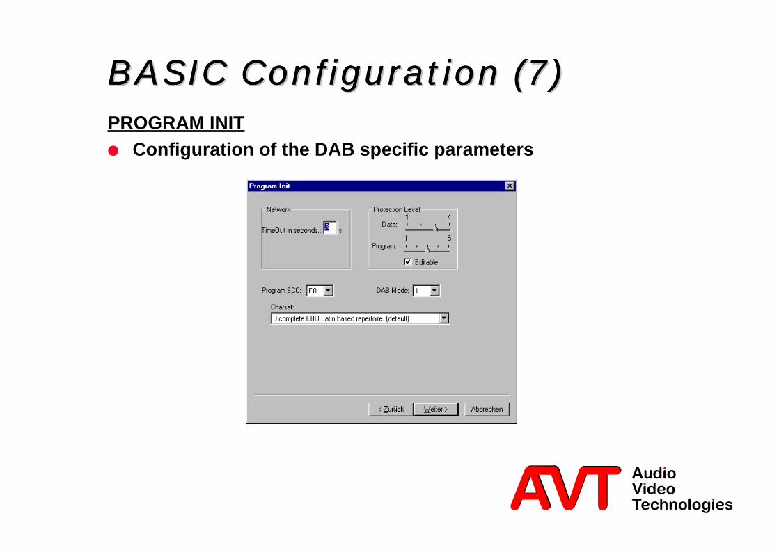
BASIC Configuration (7)BASIC Configuration (7)BASIC Configuration (7)BASIC Configuration (7)PROGRAM INITl Configuration of the DAB specific parameters

25 © AVT GmbH
BASIC ConfigurationBASIC ConfigurationBASIC ConfigurationBASIC Configuration (8) (8) (8) (8)
Ø PC parallel interface
Ø TTL-Input:– Mode 1: all FIG types can be
activated over additionalexternal hardware
– Mode 2: up to three FIGtypes can be assigned
Ø TTL-Output:– up to three FIG types can be
signalled externally
CONDITIONAL FIG FILESl Configuration of which hardware
will activate the FIGs
26 © AVT GmbH
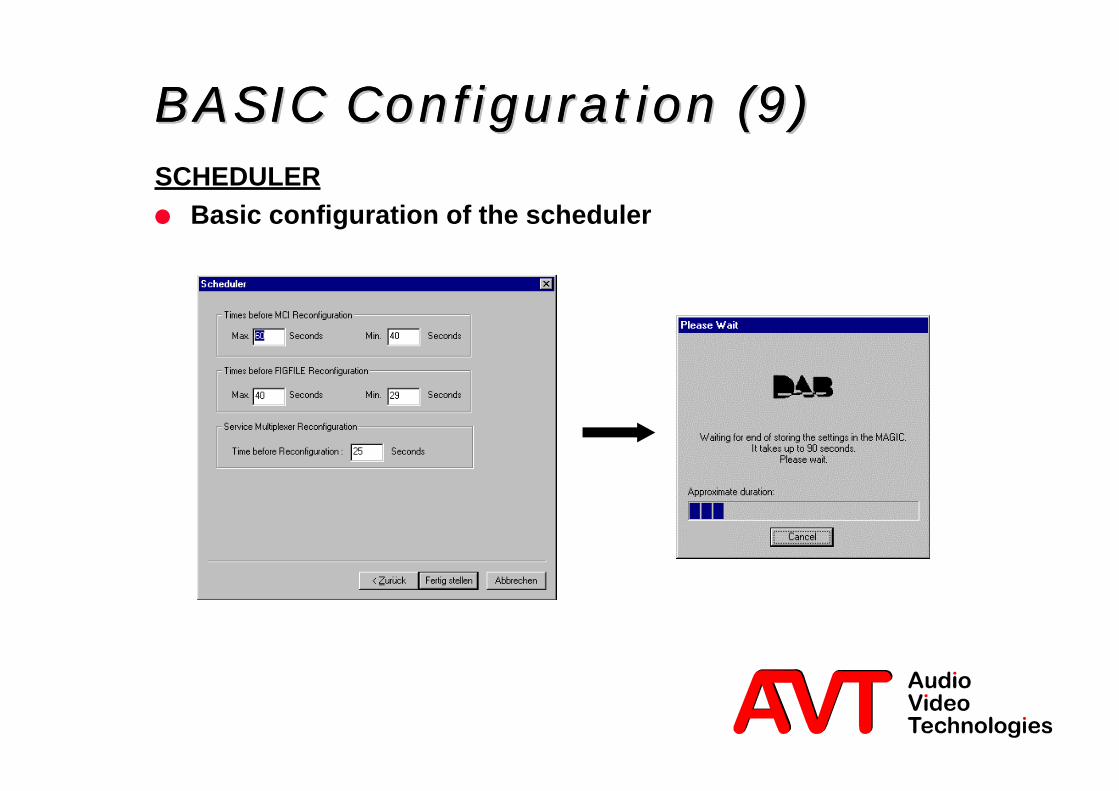
BASIC ConfigurationBASIC ConfigurationBASIC ConfigurationBASIC Configuration (9) (9) (9) (9)SCHEDULERl Basic configuration of the scheduler

28 © AVT GmbH
Main Manager (1)Main Manager (1)Main Manager (1)Main Manager (1)
Stream Window
FIG File Window
SPP select
Stream add/delete
„Working configuration“
„Next Configuration“
„Present Configuration“
Activate CFMService Multiplexer Status
Activate FIG Encoder
MCIs and FIGs stored in the EMUX
Scheduled re-configuration
Express re-configuration
Activate Message Browser
Status bar:EMUXEncoderSTI inputPC connection

29 © AVT GmbH
Main Manager (2)Main Manager (2)Main Manager (2)Main Manager (2)l System StatusØ Additional alarms are displayed with redundant operation
Present SPP
Present Configuration
Next Configuration
Implementation time of next re-configuration
Time remaining untilnext re-configuration
Cancel re-configurationSoftware control
for FIG files
Alarms as displayedin the MAGIC Basic
Further alarms fromEncoders

30 © AVT GmbH
Main Manager (3)Main Manager (3)Main Manager (3)Main Manager (3)l Symbols in the Task BarØ Displays the status of the complete system
Present display ofService Provider Profile
(Display with double click).
Status of theService Controller
connection (Software)with the Ensemble
Multiplexer. With an errordisplay flashes red.
Shows softwareactivity of the
Control File Manager.
Shows whether theScheduler
is active or not.
Shows whether theFIG Encoder
is loaded or not.

31 © AVT GmbH
Main Manager (4)Main Manager (4)Main Manager (4)Main Manager (4)l Special Menu Items (1)
Synchronisesthe PC time of
the servicecontroller withthe EnsembleMultiplexer.
Should alwaysbe activated.
Requests thepresent countervalue from theEMUX. Will runautomatically inevery case and
is only forservice
purposes.
Re-initialises theconnectionbetween theEnsemble
Multiplexer andthe ServiceMultiplexer.
Useful when theconnection has
errors over along period.

32 © AVT GmbH
Main Manager (5)Main Manager (5)Main Manager (5)Main Manager (5)l Setting up of a Log File
Activation of the recording

33 © AVT GmbH
Main Manager (6)Main Manager (6)Main Manager (6)Main Manager (6)
Shows the MCI configurationpresently stored in the Ensemble
Multiplexer associated ServiceProvider Profile.

34 © AVT GmbH
Main Manager (7)Main Manager (7)Main Manager (7)Main Manager (7)
Displays the MCIs and FIG files storedin the Ensemble Multiplexer in relation
to its own Service Provider Profile.
The list can be requested again andunused configurations can be deleted.

36 © AVT GmbH
Multiplex Configuration Information (MCI)Multiplex Configuration Information (MCI)generated under Control File Manager (CFM)generated under Control File Manager (CFM)
Setting up Auto Streams - OverviewSetting up Auto Streams - OverviewSetting up Auto Streams - OverviewSetting up Auto Streams - Overview
Service Provider Profile (SPP)Service Provider Profile (SPP)selection (only with first stream)selection (only with first stream)
Audio-Stream assignmentAudio-Stream assignment (Mode, data rate, etc.) (Mode, data rate, etc.)
ReconfigurationReconfigurationimplementationimplementation
(scheduled or Express)(scheduled or Express)
Setting up furtheraudio streams until every
Encoder has its ownaudio stream.

37 © AVT GmbH
Setting up an Audio Stream (1)Setting up an Audio Stream (1)Setting up an Audio Stream (1)Setting up an Audio Stream (1)l Selection of the Service Provider Profile (SPP) for the actual
working configuration.
Assigned SPPs are time anddate marked.For example:2000091916_19_13 means:The SPP was set up on19.09.2000 at 16:19:13 hours.Always only one SPP is valid.However configurations forother SPPs can be prepared.

38 © AVT GmbH
Setting up an Audio-Stream (2)Setting up an Audio-Stream (2)Setting up an Audio-Stream (2)Setting up an Audio-Stream (2)l A new audio stream can be assigned by clicking „+“
Workingconfiguration
activated!
Reconfigurationcannot yet be
activated!
Control FileManager cannot
be called up!

39 © AVT GmbH
Setting up an Audio Stream (3)Setting up an Audio Stream (3)Setting up an Audio Stream (3)Setting up an Audio Stream (3)l Two types of streams are possibleØ AudioØ Data (externally provided)

40 © AVT GmbH
Setting up an Audio Stream (4Setting up an Audio Stream (4Setting up an Audio Stream (4Setting up an Audio Stream (4))))l Selecting the Encoder to which the audio stream is to be alignedl Selection of the coding algorithml Option: Low Sample Frequency (24-kHz sample frequency)Ø Only useful for low data rates

41 © AVT GmbH
Setting up an Audio Stream (5)Setting up an Audio Stream (5)Setting up an Audio Stream (5)Setting up an Audio Stream (5)l Selection of the Audio data rateØ The maximum data rate that can be set is dependent on the basic
configuration of the Encoder
l Further audio streams can be assigned

43 © AVT GmbH
Generating the MCI (1)Generating the MCI (1)Generating the MCI (1)Generating the MCI (1)l Generation of the MCI is done by calling up the Control File Manager
(CFM)
44 © AVT GmbH
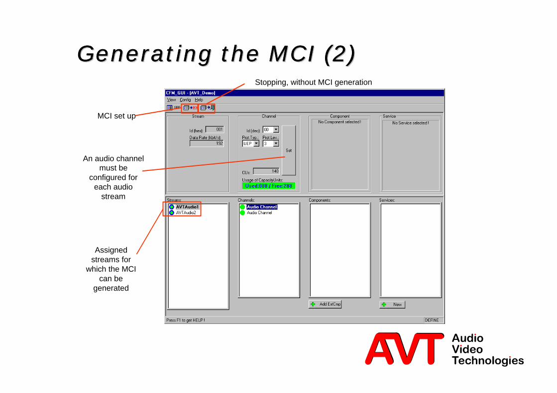
Generating the MCI (2)Generating the MCI (2)Generating the MCI (2)Generating the MCI (2)
Assignedstreams for
which the MCIcan be
generated
Stopping, without MCI generation
MCI set up
An audio channelmust be
configured foreach audio
stream
45 © AVT GmbH
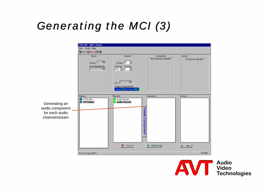
Generating the MCI (3)Generating the MCI (3)Generating the MCI (3)Generating the MCI (3)
Generating anaudio component
for each audiochannel/stream

46 © AVT GmbH
Generating the MCI (4)Generating the MCI (4)Generating the MCI (4)Generating the MCI (4)

47 © AVT GmbH
Generating the MCI (5)Generating the MCI (5)Generating the MCI (5)Generating the MCI (5)
Assign newService

48 © AVT GmbH
Generating the MCI (6)Generating the MCI (6)Generating the MCI (6)Generating the MCI (6)
A label must be given for the service.This will be displayed on the receiver.
Letters marked in black are shown asshort labels on the receiver.
Short Label (max. 8 characters) markwith the mouse (black background)
49 © AVT GmbH
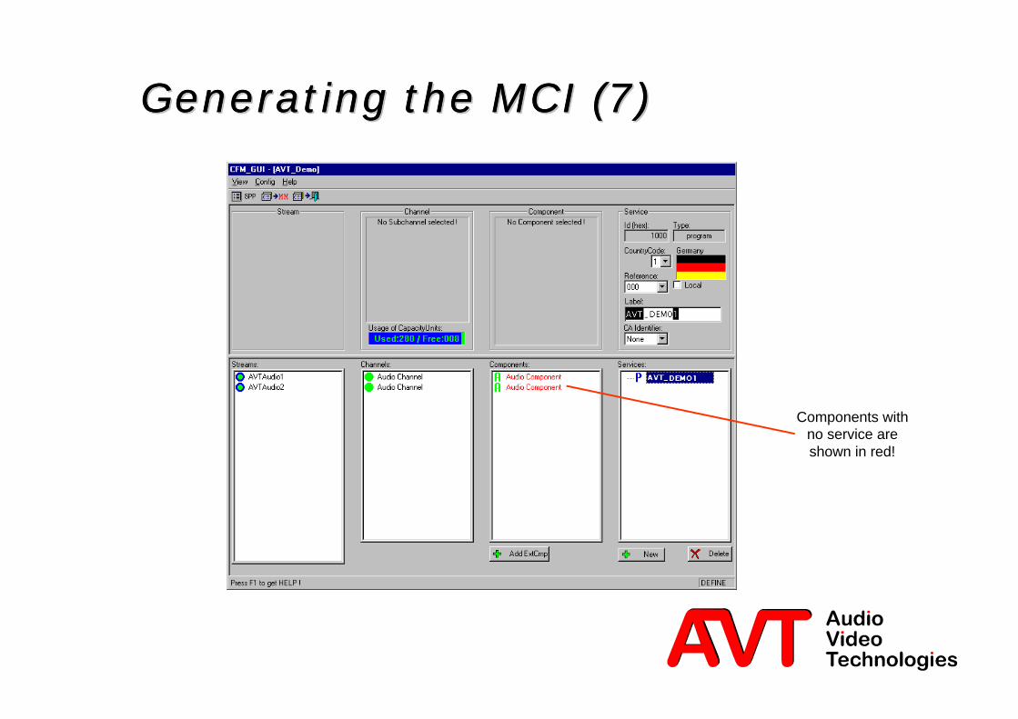
Generating the MCI (7)Generating the MCI (7)Generating the MCI (7)Generating the MCI (7)
Components withno service areshown in red!

50 © AVT GmbH
Generating the MCI (8)Generating the MCI (8)Generating the MCI (8)Generating the MCI (8)
Componentselection
Componentsadded to the
service

51 © AVT GmbH
Generating the MCI (9)Generating the MCI (9)Generating the MCI (9)Generating the MCI (9)
Components added to the service
Component can be given labels. Thismakes sense when multiple
components are defined in oneservice.
Short Label (8 characters). Mark withthe mouse (black background)

52 © AVT GmbH
Generating the MCI (10)Generating the MCI (10)Generating the MCI (10)Generating the MCI (10)
Set up further servicefor the next audio
component.
Only for multiplelanguage programsmust the next audio
component be set-upunder the same
service.

53 © AVT GmbH
Generating the MCI (11)Generating the MCI (11)Generating the MCI (11)Generating the MCI (11)

54 © AVT GmbH
Generating the MCI (12)Generating the MCI (12)Generating the MCI (12)Generating the MCI (12)Exports the MCI to
theMain Manager

56 © AVT GmbH
Reconfiguration (1)Reconfiguration (1)Reconfiguration (1)Reconfiguration (1)l Activating Scheduled (R) or Express Reconfiguration (ER)
Configuration definedbut not yet activated

57 © AVT GmbH
Reconfiguration (2)Reconfiguration (2)Reconfiguration (2)Reconfiguration (2)l Selection of FIG files to be activated

58 © AVT GmbH
Reconfiguration (3)Reconfiguration (3)Reconfiguration (3)Reconfiguration (3)l Audio programs can now be heard on a DAB receiver
Activatedconfiguration

59 © AVT GmbH
Reconfiguration (4)Reconfiguration (4)Reconfiguration (4)Reconfiguration (4)l Reconfiguration with the scheduler functions is identicallyØ A configuration previously stored can be activated at a particular time
(daily, weekly, date)
A scheduledreconfiguration
Starts and stops thescheduler

61 © AVT GmbH
Setting up a FIG FileSetting up a FIG FileSetting up a FIG FileSetting up a FIG Filefor examplefor examplefor examplefor example
Traffic AnnouncementTraffic AnnouncementTraffic AnnouncementTraffic Announcement
62 © AVT GmbH
FIG: Traffic AnnouncementFIG: Traffic AnnouncementFIG: Traffic AnnouncementFIG: Traffic Announcementl Information on the FIG taken from
TR 101 496-1/2/3: DAB System: Guidelines and Rules for Implementation and Operation, Volume 2– here chapter 3.6.8
l Classification of the following items:Ø Are the FIGs available (released through the Ensemble Provider)?
Ø Which FIGs are dependent on one another?– Announcement Support (FIG 0/18)– Announcement Switch (FIG 0/19)

63 © AVT GmbH
Setting up a FIG File (1)Setting up a FIG File (1)Setting up a FIG File (1)Setting up a FIG File (1)l FIG Files = Fast Information GroupØ Will be used for the signalling of specific information, as e.g. Announcements,
TMC, Frequency Linking etc.
Ø 2 Types– Static, e.g. the MCI with included labels– Conditional, e.g. Traffic announcements Calls up the FIG
Encoder in thepresent configuration
allows only thedisplay of the FIG.
Usefully the presentconfiguration can bestored and changed
to the workingconfiguration. The
present configurationcan be loaded there
and revised.

64 © AVT GmbH
Setting up a FIG File (2)Setting up a FIG File (2)Setting up a FIG File (2)Setting up a FIG File (2)For a Traffic
Announcement theAnnouncement
Support must first ofall be defined for eachservice (Compare TPwith RDS). This FIG is
static.
Afterwards theAnnouncement
Switch can be set up(Compare TA withRDS). This FIG is
dynamic thusconditional.
Start FIG Encoderor
double click on FIG

65 © AVT GmbH
Setting up a FIG File (3)Setting up a FIG File (3)Setting up a FIG File (3)Setting up a FIG File (3)
Interrupting the FIGEncoder
Exports the FIG to theMain Manager
Starts the FIGBrowser
Starts theFIG List
Displays Mode
Same function onlydifferent display

66 © AVT GmbH
Setting up a FIG File (4)Setting up a FIG File (4)Setting up a FIG File (4)Setting up a FIG File (4)FIG ListFIG Browser

67 © AVT GmbH
Setting up a FIG File (5)Setting up a FIG File (5)Setting up a FIG File (5)Setting up a FIG File (5)
Selects for whichservice the
AnnouncementSupport
should be valid
Announcement TypesAnnouncements whichare not limited to any
program (compare withEON on RDS)

68 © AVT GmbH
Setting up a FIG File (6)Setting up a FIG File (6)Setting up a FIG File (6)Setting up a FIG File (6)
Multiple Announcement typescan be selected simultaneously
Service selection
69 © AVT GmbH
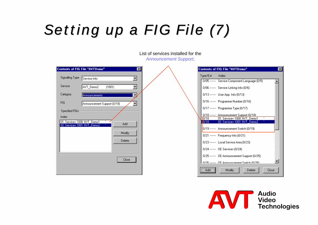
Setting up a FIG File (7)Setting up a FIG File (7)Setting up a FIG File (7)Setting up a FIG File (7)List of services installed for the
Announcement Support.

70 © AVT GmbH
Setting up a FIG File (8)Setting up a FIG File (8)Setting up a FIG File (8)Setting up a FIG File (8)
Export to the Main Manager
Restart the FIG Encoder toselect Announcement Switching

71 © AVT GmbH
Setting up a FIG-File (9)Setting up a FIG-File (9)Setting up a FIG-File (9)Setting up a FIG-File (9)l Giving the FIG file a namel Defining whether a static or a conditional FIG file should be set up

72 © AVT GmbH
Setting up a FIG File (10Setting up a FIG File (10Setting up a FIG File (10Setting up a FIG File (10))))l Starting the FIG Encoderl Operating the FIG with the FIG List
Set up anAnnouncement

73 © AVT GmbH
Setting up a FIG File (11Setting up a FIG File (11Setting up a FIG File (11Setting up a FIG File (11))))
Only oneAnnouncement Typeshould be selected!
External Trigger, i.e.by Software or
Hardware
Arrangement of theaudio programs
Value will begenerated
automatically.
Indicates whether theAnnouncement is new
or repeated.
optional

74 © AVT GmbH
Setting up a FIG File (12)Setting up a FIG File (12)Setting up a FIG File (12)Setting up a FIG File (12)
Export to the Main Manager
FIGs are now defined and mustthen be transmitted as a
reconfiguration to the EnsembleMultiplexer.

75 © AVT GmbH
Setting up a FIG File (13)Setting up a FIG File (13)Setting up a FIG File (13)Setting up a FIG File (13)
Selection of thedesired FIGs
FIG can now beactivated ordeactivated

76 © AVT GmbH
Setting up a FIG File (14)Setting up a FIG File (14)Setting up a FIG File (14)Setting up a FIG File (14)
FIG can only be activated or deactivated bysoftware.
(Observe the conditional FIG setting in thebasic configuration (8). The input must be
deactivated.)
78 © AVT GmbH
Insertion of external dataInsertion of external dataInsertion of external dataInsertion of external data

79 © AVT GmbH
STI-D InsertionSTI-D InsertionSTI-D InsertionSTI-D Insertionl The MAGIC Systems support (chargeable option) the insertion of
two STI-D data streamsl Up to 10 STI streams can be handledØ Packet Mode DataØ FIG streams
l X.21 interface (HSD) for e.g.Ø Multimedia Data Server from FhG Erlangen
Ø External FIG input
l RS232 interface (LSD) for e.g.Ø Service Information Multiplexer
from IRT Munich

81 © AVT GmbH
Error detectionError detectionError detectionError detection

82 © AVT GmbH
Alarms and Error DetectionAlarms and Error DetectionAlarms and Error DetectionAlarms and Error Detectionl Calling up the Service Multiplexer Alarms
Present status of the ISO/MPEG Encoder:? Synchronised: Encoder is ok? Not synchronised: Encoder is incorrectly configured? Deactivated: Encoder is deactivated
Present status of the complete system:? A and B alarms, classification given at present by files.? A and B alarms can be outputted at USER I/O interface(Pin 2 and Pin 3)
83 © AVT GmbH
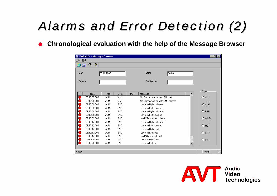
Alarms and Error Detection (2)Alarms and Error Detection (2)Alarms and Error Detection (2)Alarms and Error Detection (2)l Chronological evaluation with the help of the Message Browser

84 © AVT GmbH
Alarms and Error DetectionAlarms and Error DetectionAlarms and Error DetectionAlarms and Error Detection (3) (3) (3) (3)l Overview of system set-ups

86 © AVT GmbH
RedundancyRedundancyRedundancyRedundancy

87 © AVT GmbH
Redundancy - System DescriptionRedundancy - System DescriptionRedundancy - System DescriptionRedundancy - System DescriptionService
Controller PC
2-Mbit/s Splitter/2-Mbit/s Splitter/SwitcherSwitcher
USER I/O USER I/O
COM 1 COM 2
2-M
bit
/s S
TI-
D/C
2-M
bit
/s S
TI-
D/C
2-M
bit
/s S
TI-
C
2-M
bit
/s S
TI-
C
Sig
nal
ling
Co
ntr
ol
(Ctr
l.)
2-M
bit
/s S
TI-
C
2-M
bit
/s S
TI-
D/C
MAGIC DAB System MAGIC DAB System
2-Mbit/s ETI
2-Mbit/s STI-D/C
STI monitoring decoder
ETI monitoring decoder
DAB Ensemble-Multiplexer
Monitoring
88 © AVT GmbH
Redundant OperationRedundant OperationRedundant OperationRedundant Operationl Redundant operation must consist of two complete identical
Service Multiplexers and Encoders.l The configuration of both systems will be simultaneously activated.l Only one Service Controller PC with one STI Licence is
recommended.l A central element of a redundant system is the 2-Mbit/s
Splitter/Switcher.l The switcher is bistable, therefore both systems have equal priority.l Interruption time of the audio signal on switching: approx. 3 sec.l By exchanging one system the complete configuration of the active
system can be transferred to the new system.

89 © AVT GmbH
Redundancy - ConfigurationRedundancy - ConfigurationRedundancy - ConfigurationRedundancy - Configuration
Redundancy Mode will beset in the „COM Settings“
menu

90 © AVT GmbH
Redundancy - System StatusRedundancy - System StatusRedundancy - System StatusRedundancy - System Status
Redundancy status:? Active: displays active system (flashing green)? PC Disconnected: system switched off or PC connection faulty? Alarm: collected system alarms? Keep alive of MAGIC N: Both systems monitoring themselves by evaluating the clock signal? 2-Mbit/s Switch: Status of the 2-Mbit/s Splitter/Switch (AIS and no Signal)
91 © AVT GmbH
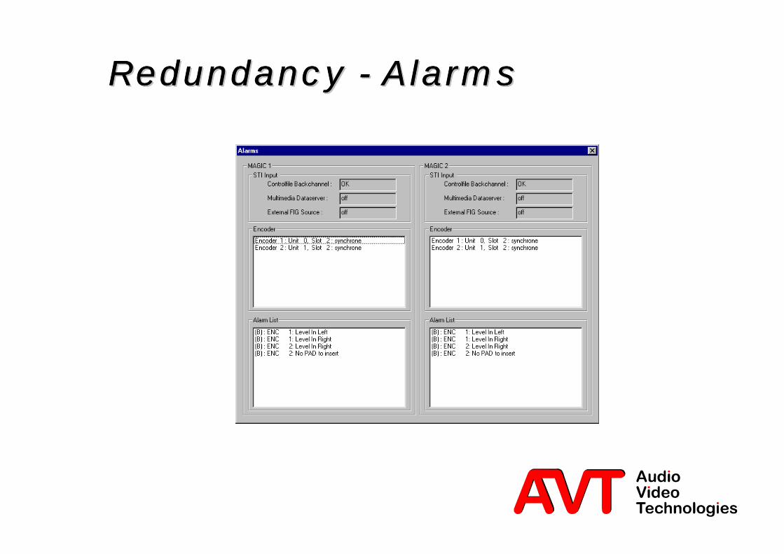
Redundancy - AlarmsRedundancy - AlarmsRedundancy - AlarmsRedundancy - Alarms

92 © AVT GmbH
Redundancy - Data TransferRedundancy - Data TransferRedundancy - Data TransferRedundancy - Data Transfer
Upon changingone system the
completeconfiguration of
the activesystem can betransferred to
the newsystem.

94 © AVT GmbH
OptionsOptionsOptionsOptions

95 © AVT GmbH
Monitoring SystemsMonitoring SystemsMonitoring SystemsMonitoring Systemsl STI and ETI Audio DecoderØ Simultaneous monitoring of all ISO/MPEG audio data streamsØ Listening to an ISO/MPEG audio signal, delivery analogue audio for cable
head-end stations.Ø 3 Relay outputs for Quality Monitoring System
– Power supply
– 2-Mbit Alarms– MPEG Alarms
ETI Audio Decoder
Audio
STI Audio Decoder
Audio + PAD
Service Provider
Audio + PAD
Audio + PAD
Audio + PAD
Audio + PAD
STI-D Data stream
NetworkNetwork
Ensemble Provider2-Mbit/s(STI-C)
2-Mbit/s (1)(STI-D&C)
2-Mbit/s (1)(STI-D&C)
ETI
2-Mbit/s(STI-C)

96 © AVT GmbH
Multiplex ofService Provider I + II
Service Provider II
Audio + PAD
Service Provider I
Audio + PAD
NetworkNetwork
2-Mbit/s (1)
2-Mbit/s (1)(STI-D&C)
(NON-STI)
2-Mbit/s (1+2)
NON-STI)
2-Mbit Drop&Insert Multiplexer2-Mbit Drop&Insert Multiplexer2-Mbit Drop&Insert Multiplexerl Mini Cross Connector for 2-Mbit linesl Up to 10 systems can be cascadedl 2-Mbit/s output signal may consist of various timeslots from different input
signals
97 © AVT GmbH
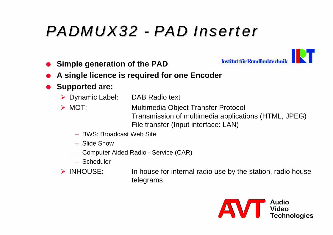
PADMUX32 - PADPADMUX32 - PADPADMUX32 - PADPADMUX32 - PAD Inserter Inserter Inserter Inserter
l Simple generation of the PADl A single licence is required for one Encoderl Supported are:Ø Dynamic Label: DAB Radio text
Ø MOT: Multimedia Object Transfer ProtocolTransmission of multimedia applications (HTML, JPEG)File transfer (Input interface: LAN)
– BWS: Broadcast Web Site
– Slide Show– Computer Aided Radio - Service (CAR)– Scheduler
Ø INHOUSE: In house for internal radio use by the station, radio housetelegrams

98 © AVT GmbH
MMDS - Multimedia Data ServerMMDS - Multimedia Data ServerMMDS - Multimedia Data ServerMMDS - Multimedia Data Serverl Two variations are available:Ø MMDS PAD System
– max. 10 PAD channels or 2 x 5 for redundant operation– simple computer hardware– LINUX operating system
Ø MMDS PAD and Packet Mode System (N-PAD)– System contents:
l 19'' computer with 5" TFT-Display
l 8-way RS232 Multiport
l X.21 card (only N-PAD Version)
l LINUX operating system
l ISDN TA or analogue modem
l MMDS Basic Softwarel PAD Software (only PAD Version)
l Packet Mode Software (only N-PAD Version)

99 © AVT GmbH
SupportSupportSupportSupportl New software can be downloaded free of charge from our Home
Page (from end Feb. 2001)Ø http://www.avt-nbg.de
l STI Training Course are provided by AVT technical staff
l Service Contracts for a duration of 6 months:Ø with previous training courseØ without previous training course