Sterling Manual. rev 9.24.04 - TEC Infrared Grills Sterling® OWNER’S MANUAL Thermal Engineering...
31
INFRA-RED Sterling ® OWNER’S MANUAL Thermal Engineering Corporation P.O. Box 868, Columbia, South Carolina 29202-0868 2741 The Boulevard, Columbia, South Carolina 29209 Telephone: (803) 783-0750 Toll-free (800) 331-0097 Fax : (803) 783-0756 Toll-free fax: (888) 581-0286 Website: www.tecinfrared.com
Transcript of Sterling Manual. rev 9.24.04 - TEC Infrared Grills Sterling® OWNER’S MANUAL Thermal Engineering...

INFRA-RED
Sterling®
OWNER’S MANUAL
Thermal Engineering Corporation
P.O. Box 868, Columbia, South Carolina 29202-0868
2741 The Boulevard, Columbia, South Carolina 29209
Telephone: (803) 783-0750 Toll-free (800) 331-0097
Fax : (803) 783-0756 Toll-free fax: (888) 581-0286
Website: www.tecinfrared.com

1
Notice to CustomerPRIOR TO INSTALLING AND USING THIS APPLIANCE,
READ THIS MANUAL FULLY AND CAREFULLY. RETAIN
THIS MANUAL FOR FUTURE REFERENCE AND HAVE
AVAILABLE AT ALL TIMES. ENSURE THAT ALL
PERSONS OPERATING THIS EQUIPMENT CAREFULLY
READ AND BECOME FAMILIAR WITH THE
INFORMATION IN THIS MANUAL.
THIS UNIT HAS BEEN CAREFULLY INSPECTED AND
PACKAGED AT THE FACTORY PRIOR TO SHIPMENT.
UPON ARRIVAL, INSPECT THE APPLIANCE
CAREFULLY FOR ANY CONCEALED DAMAGE.
IMMEDIATELY REPORT ANY DAMAGE TO YOUR
AUTHORIZED DEALER.
SHOULD YOU HAVE ANY QUESTIONS REGARDING
OPERATION OR USE OF THIS APPLIANCE, CONTACT
THERMAL ENGINEERING CORPORATION AT
(803) 783-0750 OR 1-800-331-0097.
Notice to InstallerINSTALLATION MUST CONFORM TO LOCAL CODES OR
THE NATIONAL FUEL GAS CODE, ANSI Z223.1/NFPA 54.
IN CANADA, INSTALLATION OF THIS PRODUCT
SHOULD BE IN ACCORDANCE WITH THE CAN/CGA-
B149.1 NATURAL GAS AND PROPANE INSTALLATION
CODE. FOLLOWING INSTALLATION, LEAVE THIS
OPERATIONS MANUAL WITH THE CONSUMER FOR
FUTURE REFERENCE. THIS APPLIANCE IS NOT
INTENDED FOR USE ON RECREATIONAL VEHICLES
AND/OR BOATS.
FOR YOUR SAFETYIF YOU SMELL GAS:
1. SHUT OFF GAS TO THE APPLIANCE.
2. EXTINGUISH ANY OPEN FLAME.
3. OPEN LID.
4. IF ODOR CONTINUES, IMMEDIATELY CALL YOURGAS SUPPLIER OR YOUR FIRE DEPARTMENT.
FOR YOUR SAFETY1. DO NOT STORE OR USE GASOLINE OR OTHER
FLAMMABLE VAPORS OR LIQUIDS IN THEVICINITY OF THIS OR ANY OTHERAPPLIANCE.
2. AN LP CYLINDER NOT CONNECTED FOR USESHALL NOT BE STORED IN THE VICINITY OFTHIS OR ANY OTHER APPLIANCE.
Warnings Notices
Warnings to CustomerDO NOT INSTALL OR OPERATE THIS APPLIANCE
WITHOUT HAVING CAREFULLY READ THIS MANUAL.
FOR FUTURE REFERENCE, HAVE THIS MANUAL
AVAILABLE WHILE USING THIS APPLIANCE AND
ALWAYS FOLLOW THE INSTRUCTIONS PROVIDED.
NEVER ATTEMPT TO MAKE CONVERSIONS OR
MODIFICATIONS TO YOUR GRILL WITHOUT FIRST
OBTAINING WRITTEN INSTRUCTIONS FROM THERMAL
ENGINEERING CORPORATION.
DO NOT STORE A SPARE GAS CYLINDER UNDER OR
WITHIN 15 FEET OF THIS GRILL, ANY OTHER OPEN
FLAME, HEAT PRODUCING APPLIANCE OR HEAT
SOURCE. FAILURE TO FOLLOW THESE INSTRUCTIONS
CAN RESULT IN A FIRE CAUSING DEATH OR SERIOUS
INJURY OR PROPERTY DAMAGE.
DO NOT ALLOW YOUR LP GAS CYLINDER TO BE FILLED
BEYOND 3/4 FULL.
NATIONALLY REGISTERED TESTING LABORATORY
U.S. Patent # 4886044
U.S. Patent # 4321857
Des. 266,050© Thermal Engineering Corporation
Revision (08/04)

Lifetime Limited Warranty
2 Revised 08/04
EXPRESS WARRANTIES
Thermal Engineering Corporation (TEC) warrants this grill to be free of defects in material andworkmanship when subjected to normal domestic use and service from the date of purchase.
LIFETIME
All stainless steel components other than cooking grids and stainless steel burner components arewarranted indefinitely. This includes the hood, cooking unit structure, side-shelf, pedestal and cabinet.
TEN (10) YEARS
All components not covered by the lifetime warranty above are warranted for ten (10) years.
UNDER THIS WARRANTY
We will, at our option, repair or replace any component part deemed by TEC to be defective whenreturned to the TEC factory, freight prepaid, within the warranty period. Prior to authorization ofrepair or replacement, you must supply the date of original purchase and serial number of your grill.
This warranty excludes damage caused by failure to follow the instructions in your Owner’s Manual oralteration of the grill’s structure or components, or from operator abuse, negligence or accident.
DISCLAIMER OF IMPLIED WARRANTIES
This warranty excludes incidental and consequential damages. Except as stated above, all otherwarranties, including implied warranties of merchantability and fitness for a particular purpose, areexcluded.
If you have questions concerning this warranty, please call your local authorized TEC dealer or call usat (803) 783-0750 or 1-800-331-0097.
MODEL #:
SERIAL #:
(See rating plate found under Drip Tray, back right corner of grill.)
DEALER NAME:
DEALER TELEPHONE:
(Complete the above information for future reference.)
THERMAL ENGINEERING CORPORATIONP.O. Box 868, Columbia, South Carolina 29202-0868
2741 The Boulevard, Columbia, South Carolina 29209
Telephone: (803) 783-0750 Toll-free (800) 331-0097
Facsimile: (803) 783-0756 Toll-free (888) 581-0286
Website: www.tecinfrared.com

3
Dear TEC Infra-Red Grill Owner:
Congratulations on selecting a TEC Infra-Red as your grill of choice. You’re among a select groupwho truly appreciate fine cooking and demand the best.
I know you’ll be pleased with your grill’s performance.
Over the years, we’ve invested great resources in developing a grill that’s truly unique — from thesturdy, long-lasting construction to the unparalleled infra-red cooking process. But I’m sure that’s whyyou selected a TEC grill over all others. You must have seen that our commitment to quality andinnovation would provide you with years of satisfying use.
We’ve developed this manual to give you an overview of your grill and to help you get the most fromit. We’ve included some cooking guidelines for you to use until you develop your own techniques.We’ve also included vital information about how to set up, operate and maintain your grill safely andcorrectly, so I urge you to read it carefully before first using your grill. If, after reviewing thisinformation, you have any questions whatsoever, please call your Authorized TEC Dealer or ourCustomer Service Department for help.
As I’m sure you know, we also offer a complete line of accessories that afford you a wide range ofopportunities for new and interesting uses of your grill. Some of them, like our rotisserie, are optionsfamiliar to everyone. Others, like our deep fryer and wok, are truly unique enhancements that allowyou to be adventuresome and inventive with your grill. Your dealer can tell you more about all theaccessories we offer and their many uses.
If you have comments, suggestions, or even compliments, please pass them along to us. We arecontinually in search of ways we can improve our customers’ experiences with their grills, startingwhen they first remove them from the box and continuing as they use them over the years. Hearingwhat you feel we could improve, as well as what you especially like about our products and services, isessential to this effort. I hope you’ll agree that the product registration form is a convenient, easy wayto accomplish this.
Thanks for selecting TEC — I wish you years of great grilling!
Best regards,
THERMAL ENGINEERING CORPORATION
W.H. “Bill” BestChairman and CEO

4 Revised 08/04
Installation..................................................4General OverviewPermanent Installation
Assembly ....................................................5General OverviewTools RequiredSide-shelfPedestal BaseIn-ground Post Base and Bolt-down Post BaseCabinet BaseRoll Back HoodCooking Grids and Baking Rack
Gas Connection......................................................8General OverviewLP Gas Cylinder SafetyInstalling Your LP Gas CylinderRemoving Your LP Gas CylinderQuick Disconnect InstructionsPermanent InstallationGas Leak Test
Operation............................................................11General OverviewBurner IgnitionBurner Ignition Without PilotLow Heat AdjustmentPilot Flame AdjustmentBase BrakeHazardous Locations and Conditions
Infra-red Cooking ..................................................14General OverviewInfra-red Searing MethodHelpful Hints in CookingFlame Flare-up ControlSample Cooking Methods
Maintenance and Cleaning ......................................16General OverviewProtection of BurnersCleaningMaintenanceReplacement Parts
Appendix A: Build-in Specifications............................18
Appendix B: Accessories ........................................20RotisserieBar-B-Que TrayWood Chip SmokerDeep Fryer/SteamerGriddleWokSterling® Side-burner
Appendix C - Replacement Parts................................28
Appendix D - Troubleshooting ..................................29
General OverviewWARNING: THIS GRILL IS DESIGN CERTIFIED FOR USE
OUTDOORS ONLY.
THIS GRILL SHOULD NOT BE USED IN A BUILDING,
GARAGE OR OTHER ENCLOSED AREA AND IS NOT
INTENDED FOR USE ON RECREATIONAL VEHICLES OR
BOATS.
The Sterling® is designed for permanent installation on afree-standing masonry or other suitable patio fixture. SeeAppendix A for complete build-in specifications.
The Sterling can also be attached to the optional pedestalor cabinet base, which have casters for easy movement. Itcan be locked in place by using the brake mechanism,WHICH SHOULD BE ENGAGED AT ALL TIMES located nearthe back left corner of the pedestal base or inside thecabinet base at the back left corner. (See BASE BRAKE
section on page 13 for more information.)
Figure 1 (see page 5) represents the minimum clearanceof a mobile grill to any adjacent combustibleconstruction.
WARNING: THIS OUTDOOR COOKING GAS APPLIANCE
SHALL NOT BE USED UNDER OVERHEAD
COMBUSTIBLE CONSTRUCTION.
Permanent InstallationIf you are installing your grill as a build-in or on theoptional Post Base (Sterling II only), it should be locatedso the ventilation louvers remain clear of all obstructions.The louvers are located in the front surface of the Grill’sHousing and at the rear of the Roll Back Hood. Anyaccumulation of debris will restrict the flow ofcombustion and/or ventilation air, and may result inimproper burner operation or overheating. See Table A.1for clearance specifications. Installation proceduresrelating to gas connections for permanent installationscan be found in the Gas Connection section of thismanual. Build-in opening specifications can be found inAppendix A of this manual.
Table A.1 Clearance Specifications
COMBUSTIBLE NON-COMBUSTIBLE
CONSTRUCTION CONSTRUCTION
Sides 12" 0"
Back 12" 0"
Contents Installation

5
The Post Base (Sterling II only) is designed to be installedin a bed of concrete to a depth of 17 1/2". The height ofthe grill cooking surface should be roughly 38 1/2" fromthe ground. (See Figure 4 & 5.) The line gas connectionis located on the left side of the post. The gas connectionis SAE 45° female flare.
The Post Base is constructed of stainless steel, which ishighly corrosion resistant. However, a suitable means ofcorrosion protection should be used, as necessary, due tocorrosion conditions at the installation site.
The installation of your grill must conform to local codesor, in absence of local codes, the National Fuel Gas CodeANSI Z223.1/NFPA 54. In Canada, the installationmust conform to local codes and/or the Natural Gas andPropane Installation Code CAN/CGA-B149.1.
Figure 1. Clearance To Combustible Construction
WARNING: THIS OUTDOOR COOKING GAS APPLIANCE
SHALL NOT BE USED UNDER OVERHEAD
COMBUSTIBLE CONSTRUCTION.
General OverviewSterling grills are designed for easy assembly. Both theSterling II and Sterling III are available with assembledhood. You can choose from our optional bases and side-shelves to customize your grill. Assembly procedures foreach of these options follow.
Tools Required■ Flat head screwdriver
■ Phillips screwdriver (#2)
■ Ratchet with 7/16" socket or 7/16" end wrench
Side-shelf1. Use the four (4) 1/4 - 20 x 1/2"L Phillips-head screws
from the plastic bag that contained this Owner’sManual and the TEC® Cookbook.
2. Thread two (2) Phillips-head screws approximately1/4" into the two (2) top threaded holes of the grillside panel.
3. Using the keyholes on the Side-shelf, place the Side-shelf on the 1/4" screws. Ensure that the screws slideto the top of the keyhole slots.
4. Tighten the two (2) top screws until the Side-shelf isflush but not tight against the grill side panel of theSterling gas grill.
5. Connect the remaining two (2) screws through theSide-shelf and into the bottom two (2) threadedholes of the grill side panel.
6. Tighten all four (4) screws firmly.
Figure 2. Side-shelf Attachment
Installation continued Assembly

Revised 08/046
Pedestal Base (Sterling II and III)1. Remove the Pedestal Base from the packaging
materials and set it on a level surface.
2. Place the Grill Housing on the Pedestal Base andalign the round mounting holes in the Base with thethreaded inserts in the Housing.
3. Fasten the Housing to the Base with the suppliedhardware. (Hardware needed: Four (4) each 1/4 - 20 x1/2"L hex head bolts and flat washers.) (See Figure 3.)
Figure 3. Pedestal Base
In-ground Post Base and Bolt-down Post Base(Sterling II Only)1. Install the In-ground or Bolt-down Post Base in
accordance with the instructions accompanying PostBase.
2. Fasten the Housing to the Base with the suppliedhardware. (Hardware needed: Four (4) each 1/4 - 20x 1/2 L hex head bolts and flat washers.) (See Figures4 & 5.)
Figure 4. In-ground Post (Sterling II Only)
Figure 5. Bolt-down Post (Sterling II Only)
Assembly continued
261/2"
171/2"
21/2"
GROUND
1/4 - 20 HEX. BOLT
W/ FLAT WASHER
(TYP. BOTH ENDS)
1/4 - 20 HEX. BOLTW/ FLAT WASHER(TYP. BOTH ENDS)

7
Cabinet Base (Sterling II and III)1. Remove the Cabinet Base from the packaging
materials and set it on a level surface.
2. Place the Grill Housing on the Cabinet Base andalign the round mounting holes in the Base with thethreaded inserts in the Housing.
3. Fasten the Housing to the Base with the suppliedhardware. (Hardware needed: Four (4) each 1/4-20 x1/2"L hex head bolts and flat washers.) (See Figure 6.)
Figure 6. Cabinet Base
Roll Back Hood (Sterling II and III)1. Remove the Roll Back Hood from the packaging
materials.
2. Remove the Heat Shield from the Grill Housing.(See Figure 7.)
3. Set the Hood in place on the Grill Housing.
4. Fasten the Hood to the Grill Housing with thesupplied hardware. (Hardware needed: Four (4) each#10-24 x 1/2"L screws and nuts.) (See Figure 8.)
5. Replace the Heat Shield.
Cooking Grids and Baking Rack(Sterling II and III)1. Remove the Cooking Grids and Baking Rack from
the packaging materials.
2. Set the Cooking Grids in place with the open side ofthe channels facing up and the holes toward the rearof the grill. Set the Baking Rack in place inside theRoll Back Hood.
Assembly continued
1/4 - 20 HEX. BOLTW/ FLAT WASHER(TYP. BOTH ENDS)
10-24 SCREWW/ #10 KEP NUT(TYP. BOTH ENDS)
HEAT SHIELD
Figure 7. Heat Shield
Figure 8. Roll Back Hood

Revised 08/048
Gas Connection
General OverviewWARNING: THE GAS SUPPLY HOSE SHOULD BE
INSPECTED PRIOR TO EACH USE. DO NOT USE A GAS
HOSE THAT HAS ABRASION, CUTS OR EXCESSIVE
WEAR. IF ABRASION, CUTS OR EXCESSIVE WEAR IS
EVIDENT, THE GAS SUPPLY HOSE MUST BE REPLACED
BEFORE USE. REPLACEMENT ASSEMBLY MUST BE
SPECIFIED BY TEC.
WARNING: WHEN YOUR GRILL IS STORED INDOORS,
REMOVE AND STORE THE LP GAS CYLINDER
OUTDOORS IN A PROTECTED, COOL AND DRY
LOCATION OUT OF REACH OF CHILDREN. THE
CYLINDER SHOULD NOT BE STORED IN A BUILDING,
GARAGE OR ANY OTHER ENCLOSED AREA.
Follow the procedures outlined in this section closely toensure safe and proper grill operation. The Sterling grill isoffered in one of two gas configurations: LP or Naturalgas. The pressure regulator and hose used for the LP gasconfiguration varies depending on the type of base used.Reference Table A.2 below for regulator specifications.Grills that do not use LP gas with standard 20 lb. LPcylinder must be installed by qualified personnel. Thisincludes all Natural gas and permanently installed units.Gas regulators specified by TEC should be used at alltimes.
PLEASE NOTE: When any burner using propane fuelexceeds the capacity of the propane cylinder to vaporizethe fuel, the cylinder pressure can decrease to the extentthat the appliance will not burn properly.
Refer to Table A.2 below for gas supply specifications orsee rating plate located at the grill’s right rear cornerbelow Drip Tray.
LP Gas Cylinder SafetyWARNING: WHEN PURCHASED FOR USE WITH LP
GAS, THE STERLING GRILL COMES WITH A
REGULATOR ASSEMBLY THAT USES A TYPE I CYLINDER
CONNECTION DEVICE. THIS DEVICE SHOULD ONLY BE
USED WITH A TYPE I TANK VALVE CYLINDER
CONNECTION.
NOTICE: AN LP GAS CYLINDER IS NOT PROVIDED
FROM THE FACTORY WITH THIS GRILL. HOWEVER,
ONLY APPROVED 20 LB. LP GAS CYLINDERS
CONSTRUCTED AND MARKED IN ACCORDANCE WITH
THE SPECIFICATIONS FOR LP GAS CYLINDERS OF
THE U.S. DEPARTMENT OF TRANSPORTATION (D.O.T)
OR NATIONAL STANDARD OF CANADA, CAN/CGA-B339,
CYLINDERS, SPHERES AND TUBES FOR THETRANSPORTATION OF DANGEROUS GOODS; ANDCOMMISSION, SHOULD BE USED. ALL APPROVED
CYLINDERS MUST BE EQUIPPED WITH AN INTEGRAL
COLLAR DESIGNED TO PROTECT THE CYLINDER
VALVE FROM DAMAGE, AS WELL AS A LISTED
OVERFILL PROTECTION DEVICE. DO NOT USE OR TRY
TO REPAIR A DAMAGED LP GAS CYLINDER AT ANY
TIME. CONTACT YOUR LOCAL LP GAS SUPPLIER FOR
REPLACEMENT. ALSO, YOU SHOULD ALWAYS
OBSERVE THE FOLLOWING PRECAUTIONS:
■ Store spare or extra gas cylinders at least 15 feet fromthis grill or other open flame, heat-producingappliance or heat source.
■ Do not fill your gas cylinder beyond 3/4 full.
■ Gas cylinders come with a pressure relief valve. If acylinder is subjected to excess heat, the relief valvewill open and let highly flammable gas vapor and/orliquid escape. Therefore, do not store gas cylindersnear an open flame or source of heat. Store cylindersonly in well ventilated areas.
WARNING: FAILURE TO FOLLOW THE ABOVE
PRECAUTIONS COULD RESULT IN A FIRE CAUSING
DEATH OR SERIOUS INJURY OR PROPERTY DAMAGE.
GAS, REGULATOR SUPPLY PRESSURE OPERATING PRESSURE MAIN BURNER BURNER OUTPUT
AND BASE TYPE (IN. WC (kPa), MAX/MIN) (IN. WC (kPa)) ORIFICE SIZE (DMS / DIA.) (BTU/HR. (W)/EA.)
Natural 14.0 (3.4)/5.0 (1.2) 4.0 (1.0) 46 (0.0810") 18,500 (5,422)model RV-47L (NG) stationary or post
LP 14.0 (3.4)/12.0 (3.0) 11.0 (2.7) 55 (0.0520") 18,500 (5,422)model RV-47L (LP) stationary or post
LP 125 psi (861), max 11.0 (2.7) 55 (0.0520") 18,500 (5,422)model 150 w/ hose pedestal or cabinet
Table A.2. Gas Supply Specifications

Installing Your LP Gas CylinderNOTICE: FOR YOUR SAFETY, ONLY USE THE
REGULATOR AND HOSE ASSEMBLY PROVIDED AS
ORIGINAL EQUIPMENT WITH YOUR GRILL.
REPLACEMENT ASSEMBLIES MUST ALSO BE SPECIFIED
BY TEC.
NOTICE: A FIRE EXTINGUISHER FOR CLASS A, B, C &
D FIRES SHOULD BE READILY AVAILABLE AT ALL TIMES.
WARNING: THE VENTILATION/ACCESS OPENING, IN
THE REAR OF THE PEDESTAL, MUST BE FREE AND
CLEAR FROM DEBRIS. THE GAS MUST BE TURNED OFF
AT THE SUPPLY CYLINDER WHEN THE GRILL IS NOT IN
USE.
Be sure to set the gas cylinder upright so the CylinderValve is at the top. This will ensure proper vaporwithdrawal.
When you connect your cylinder to the grill, you will feelthe coupling nipple seal when there is slight resistance.(See Figure 9.) Turn about one-half to three-quartersfurther to complete the connection. Tighten only by hand;do not use tools. If you cannot complete the finalconnection, disconnect the regulator and repeat step 7,below. If you are still unable to complete the connection,replace the valve and regulator!
Procedure:
1. In order to make sure the Cylinder Valve is fullyclosed, turn the Handwheel clockwise until it stops.
2. Turn all burner and pilot controls OFF.
3. Move your grill to an open area that’s level andengage the Base Brake. (See Figure 17.)
4. Place the gas cylinder in the space provided in theBase. Remove the protective caps from CylinderValve Outlet and Nipple, as necessary.
5. Inspect the Coupling Nut, Nipple and CylinderValve. See if there is any damage, dirt or debris.Remove dirt or debris. Replace damaged parts priorto use.
6. Inspect Regulator and Hose Assembly. See if there isany damage, dirt or debris. Remove dirt or debris.Replace damaged parts prior to use.
7. With the Regulator in your hand, insert the Nippleinto the Cylinder Valve. Make sure the Nipple iscentered in the Cylinder Valve outlet. Tighten theCoupling Nut by hand, making sure not to cross-thread the connection.
WARNING: KEEP THE VENTILATION OPENINGS OF
THE CYLINDER ENCLOSURE FREE AND CLEAR OF
DEBRIS.
9
Gas Connection continued
COUPLINGASSEMBLYFIGURE 9
INSET FIGURE
PROPANE TANK
RELEASE
CLOSE LATCH
TOP VIEW
Handwheel
Excess Flow
Valve
Cylinder
Valve
Cap & Strap
Valve
Outlet
Coupling
Nut
Regulator
Nipple
Figure 9. Coupling Assembly
Figure 10. Gas Tank Placement

Removing Your LP Gas Cylinder
Procedure:
1. Close the Cylinder Valve by turning the Handwheelclockwise until it stops.
2. Release the latch and remove the cylinder from grill.
3. Loosen the Coupling Nut by turning it counter-clockwise.
Quick Disconnect Instructions(See Figure 11.)
Procedure:
1. To connect, push back Sleeve of Socket. (See FigureA.)
2. Insert Plug (See Figure B.), release Sleeve.
3. Push Plug until Sleeve snaps forward locking Plug inSocket (See Figure C.). (THIS AUTOMATICALLYTURNS ON GAS.)
4. To disconnect, push sleeve back and pull out plug.(THIS AUTOMATICALLY SHUTS OFF GAS.)
Permanent InstallationCAUTION: GAS PIPING TO YOUR GRILL MUST BE IN
ACCORDANCE WITH LOCAL CODES. IN THE ABSENCE
OF LOCAL CODES, USE THE NATIONAL FUEL GAS
CODE ANSI Z223.1/NFPA 54 (LATEST EDITION) OR
CAN/CGA B-149.1, NATURAL GAS AND PROPANE
INSTALLATION CODE.
CAUTION: THE GAS SUPPLY MUST BE TURNED OFF AT
THE GRILL WHEN THIS APPLIANCE IS NOT IN USE.
When ordered for use with Natural gas, the Sterling grillcomes adjusted to operate with Natural gas. Qualifiedpersonnel should install the gas line. A Shut-off Valve atthe grill is required. This Valve must be design certifiedby CSA International. When using the optional PostBase, you must use the Regulator and separate hosesupplied with the Post Base. Specifications for gas supplyrequirements are listed in Table A.2 on page 8.
The grill and Shut-off Valve must be disconnected fromthe gas supply piping system during any pressure testingof the system at test pressures in excess of 1/2 PSIG (3.5kPa).
The grill must be isolated from the gas supply pipingsystem by closing its individual manual Shut-off Valveduring any pressure testing of the system at test pressuresequal to or less than 1/2 PSIG (3.5 kPa).
Gas Leak TestWARNING: DO NOT USE OPEN FLAME TO PERFORM
LEAK TEST!
WARNING: DO NOT ATTEMPT TO USE THE GRILL
WHEN YOU SMELL GAS OR FAIL A GAS LEAK TEST.
Make sure there is no open flame near the grill duringthe test. Test for leaks every time the gas connection isdisconnected.
Procedure:
1. Turn all controls OFF.
2. Open the Gas Supply Valve slowly. Apply soapywater solution to all connections including factoryconnections.
3. Look for bubbles around the connections. If bubblescan be seen, close the Valve and tighten theconnection where the bubbles are. Then, repeat steps1 and 2. Make sure you don’t over-tighten theconnections.
4. Proceed with grill use.
Gas Connection continued
10 Revised 08/04
SLEEVE
REGULATOR
TO
TO
TO
REGULATOR
REGULATOR
SOCKET
SOCKET
SLEEVE
TO
TO
TO
GRILL
GRILL
GRILL
PLUG
PLUG
(FIGURE C.)
(FIGURE B.)
(FIGURE A.)
Figure 11. Quick Disconnect Fittings

General OverviewNOTICE: THE BURNER VENTURI TUBES SHOULD BE
INSPECTED FOR SPIDER WEBS AND OTHER
OBSTRUCTIONS PRIOR TO EACH USE. IF ANYTHING IS
FOUND, CLEAN THE TUBES COMPLETELY. A CLOGGED
TUBE CAN LEAD TO A FIRE BENEATH THE GRILL.
NOTICE: NEVER PLACE FOOD OVER A BURNER THAT
IS NOT IN OPERATION. FOOD DRIPPINGS WILL NOT BE
INCINERATED AND THE SMALL PORTS MAY BECOME
CLOGGED. THE BURNER SHOULD NOT COME IN
CONTACT WITH WATER OR OTHER CLEANING FLUIDS.
IT COULD DAMAGE THE BURNER, CAUSING IT TO
FUNCTION IMPROPERLY.
All Sterling grills are equipped with a Pilot Burner. APilot makes lighting your grill safer. In addition, thissafety feature will re-ignite the burner if it goes out whileyou are cooking. Pilot Burners take a certain amount oftime to ignite because gas must first flow from the gascylinder to the pilot tip. When lighting the Pilot, be sureto use the following instructions.
Burner Ignition
Procedure:
1. Open the Hood, ensure all valves are closed and thatthe cooking surface of the grill is not covered.
2. For LP gas, open the Gas Valve on Cylinder.
For Natural gas, open the Gas Valve in the mainline.
3. Depress and turn the Pilot Output Knob to (ON). (See Figure 12.)
Figure 12. Pilot Output Knob
4. Slowly rotate the Igniter Knob clockwise twice andcheck for pilot flame. (See Figure 14.) If a flame isnot present, turn the Pilot Valve Knob to OFF andwait 5 minutes. Then repeat steps 3 and 4.
5. Rotate the Burner Output Knobs to (HIGH).(See Figure 13.)If the burners do not ignite within 5seconds, turn Burner Output Knobs to OFF andwait 5 minutes, and repeat.
6. Operate on (HIGH) until burners glow uniformly,then turn the Burner Output Knobs to the desiredcooking level.
7. To extinguish the flame, depress and rotate the BurnerOutput Knobs and the Pilot Output Knob to OFF.
8. For LP gas, close the Gas Cylinder Valve by turningthe handwheel clockwise. For Natural gas, close thegas valve in the main line.
Figure 13. Burner Output Knob
CAUTION: WHEN COOKING WITH HOOD CLOSED,
THE KNOB POSITION MARKED* IS THE MAXIMUM
TEMPERATURE SETTING TO BE USED. THE BURNER
OUTPUT SHOULD NEVER BE INCREASED BEYOND THIS
POSITION WITH THE HOOD CLOSED.
Burner Ignition Without PilotCAUTION: DO NOT HOLD A MATCH ABOVE THE
SCREEN WHEN LIGHTING THE BURNER MANUALLY.
PLACE THE MATCH DIRECTLY ON THE BURNER
SCREEN, THEN PULL YOUR HAND AWAY FROM THE
GRILL.
Operation
11
PILOT GASON
BURNER HIGH
BURNER HIGH WITH HOOD CLOSED
BURNER LOW
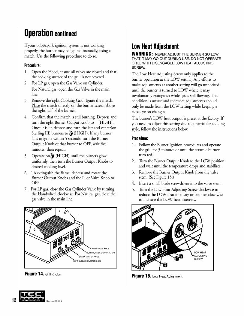
If your pilot/spark ignition system is not workingproperly, the burner may be ignited manually, using amatch. Use the following procedure to do so.
Procedure:
1. Open the Hood, ensure all valves are closed and thatthe cooking surface of the grill is not covered.
2. For LP gas, open the Gas Valve on Cylinder.
For Natural gas, open the Gas Valve in the mainline.
3. Remove the right Cooking Grid. Ignite the match.Place the match directly on the burner screen abovethe right half of the burner.
4. Confirm that the match is still burning. Depress andturn the right Burner Output Knob to (HIGH).Once it is lit, depress and turn the left and center(onSterling III) burners to (HIGH). If any burnerfails to ignite within 5 seconds, turn the BurnerOutput Knob of that burner to OFF, wait fiveminutes, then repeat.
5. Operate on (HIGH) until the burners glowuniformly, then turn the Burner Output Knobs todesired cooking level.
6. To extinguish the flame, depress and rotate theBurner Output Knobs and the Pilot Valve Knob toOFF.
7. For LP gas, close the Gas Cylinder Valve by turningthe Handwheel clockwise. For Natural gas, close thegas valve in the main line.
Low Heat AdjustmentWARNING: NEVER ADJUST THE BURNER SO LOW
THAT IT MAY GO OUT DURING USE. DO NOT OPERATE
GRILL WITH DISENGAGED LOW HEAT ADJUSTING
SCREW.
The Low Heat Adjusting Screw only applies to theburner operation at the LOW setting. Any efforts tomake adjustments at another setting will go unnoticeduntil the burner is turned to LOW where it mayinvoluntarily extinguish while gas is still flowing. Thiscondition is unsafe and therefore adjustments shouldonly be made from the LOW setting while keeping aclose eye on changes.
The burner’s LOW heat output is preset at the factory. Ifyou need to adjust this setting due to a particular cookingstyle, follow the instructions below.
Procedure:
1. Follow the Burner Ignition procedures and operatethe grill for 5 minutes or until the ceramic burnersturn red.
2. Turn the Burner Output Knob to the LOW positionand wait until the temperature drops and stabilizes.
3. Remove the Burner Output Knob from the valvestem. (See Figure 15.)
4. Insert a small blade screwdriver into the valve stem.
5. Turn the Low Heat Adjusting Screw clockwise toreduce the LOW heat intensity or counter-clockwiseto increase the LOW heat intensity.
Figure 15. Low Heat Adjustment
Operation continued
12 Revised 08/04
LOW HEAT
ADJUSTING
SCREWLEFT BURNER OUTPUT KNOB
SPARK IGNITER KNOB
RIGHT BURNER OUTPUT KNOB
PILOT VALVE KNOB
Figure 14. Grill Knobs
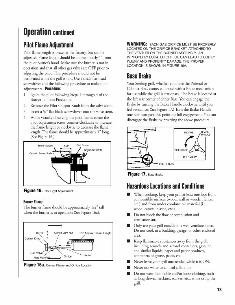
Pilot Flame AdjustmentPilot flame length is preset at the factory, but can beadjusted. Flame length should be approximately 1” fromthe pilot burner’s hood. Make sure the burner is not inoperation and that all other gas valves are OFF prior toadjusting the pilot. This procedure should not beperformed while the grill is hot. Use a small flat-headscrewdriver and the following procedure to make pilotadjustments. Procedure:
1. Ignite the pilot following Steps 1 through 4 of theBurner Ignition Procedure.
2. Remove the Pilot Output Knob from the valve stem.
3. Insert a 1/8" flat-blade screwdriver into the valve stem.
4. While visually observing the pilot flame, rotate thepilot adjustment screw counter-clockwise to increasethe flame length or clockwise to decrease the flamelength. The flame should be approximately 1” long.(See Figure 16.)
Burner FlameThe burner flame should be approximately 1/2” tallwhen the burner is in operation (See Figure 16a).
WARNING: EACH GAS ORIFICE MUST BE PROPERLY
LOCATED ON THE ORIFICE BRACKET, ATTACHED TO
THE VENTURI ON THE BURNER ASSEMBLY. AN
IMPROPERLY LOCATED ORIFICE CAN LEAD TO BODILY
INJURY AND PROPERTY DAMAGE. THE PROPER
LOCATION IS SHOWN IN FIGURE 16A.
Base BrakeYour Sterling grill, whether you have the Pedestal orCabinet Base, comes equipped with a Brake mechanismfor use while the grill is stationary. The Brake is located atthe left rear corner of either Base. You can engage theBrake by turning the Brake Handle clockwise until youfeel resistance. (See Figure 17.) Turn the Brake Handleone half turn past this point for full engagement. You candisengage the Brake by reversing the above procedure.
Hazardous Locations and Conditions■ When cooking, keep your grill at least one foot from
combustible surfaces (wood, wall or wooden fence,etc.) and from under combustible material (i.e.wood, canvas, plastic, etc.).
■ Do not block the flow of combustion andventilation air.
■ Only use your grill outside in a well-ventilated area.Do not cook in a building, garage, or other enclosedarea.
■ Keep flammable substances away from the grill,including aerosols and aerosol containers, gasolineand similar liquids, paper and paper products,containers of grease, paint, etc.
■ Never leave your grill unattended while it is ON.
■ Never use water to control a flare-up.
■ Do not wear flammable and/or loose clothing, suchas long sleeves, neckties, scarves, etc., while using thegrill.
Operation continued
13
Figure 16a. Burner Flame and Orifice Location
1/2” Approx. Flame LengthOrifice Jam Nut
VenturiOrifice
Bezel
Control Knob
Gas Valve
Gas Manifold
Burner Screen ~1.00” Pilot Burner
Ignition Electrode
Ceramic Burner Surface
Figure 16. Pilot Light Adjustment
INSET FIGURE
DISENGAGE
ENGAGE BRAKE HANDLE
TOP VIEW
Figure 17. Base Brake

General OverviewNow that you are ready to begin cooking, you can enjoycooking outdoors quickly and effortlessly. In minutes,you can enjoy steaks, hamburgers, poultry, pork chops,roasts, fish and other foods. You can also cook moreslowly if you wish. TEC’s optional accessories aredesigned to enhance your grill’s versatility.
Infra-red Searing MethodSearing is a process that seals juices in food by cookingwith intense heat for a short period of time. The juicesstay in the meat where they belong and the outside getscoated with flavorful grilling aroma. For best results,follow these procedures when cooking.
The intense Infra-red energy generated by your TEC grillhas many advantages. For example, meat is evenly cookedthroughout. Also, grease and food particles burn up oncontact with the burner and change into flavorful vaporsthat cook back into your food.
Searing Method:
1. Follow the Burner Ignition procedures and operatethe grill for 5 minutes or until the ceramic burnersturn red.
2. Set the Burner Output Knobs to HIGH and placethe food on Cooking Grid for 1-2 minutes, or untilfood lifts without sticking.
3. Turn the food and repeat Step 2.
4. Depending upon your taste, continue cooking onHIGH, turning the food frequently, or adjust theBurner Output Knob between LOW and “medium”and continue cooking until the food is cooked toyour satisfaction. Turn as necessary (generally everyone to three minutes).
During the searing period, flashing might occur whenjuices vaporize on contact with the Cooking Grid andburner surfaces. The flashes and smoke greatly enhancethe flavor by “char-cooking” your food.
The intense Infra-red energy generated by your TEC grillhas other advantages. For example, food is evenly cookedthroughout. Also, upon contact with the Cooking Gridsand burners, drippings vaporize into flavorful smoke thatcooks back into the food.
Helpful Hints in Cooking1. Cover the Drip Tray with foil. Be careful not to
cover the ventilation openings at front of the DripTray. This helps with clean-up, too.
2. Line the inner walls of the Heat Shield with foil.
3. Use the proper tools. Long handled tongs, spatula,knife, and mitts or a hot pad for handling hot items.When turning or moving foods, use tongs or aspatula, instead of a fork. Piercing the food with afork lets the natural juices and flavor escape.
4. Monitor meat temperature. Bring large cuts of meat,roast, or fowl to room temperature before cooking.Smaller meat cuts such as hamburgers, wieners, orsmall steaks may be cooked directly from therefrigerator. Note: TEC does not recommendcooking portion meats from a frozen state.
5. Start slowly. Infra-red grilling is unlike other outdoorcooking methods. It may take you time to get usedto the fast cooking process. As a benchmark, foodswhich generally cook in 20 minutes or less onconventional grills cook in about one-half theconventional time on a TEC Infra-red grill. Pleaserefer to the section entitled SAMPLE COOKING
METHODS on page 15.
Flame Flare-up ControlNOTICE: NEVER DOUSE A FLARE-UP WITH WATER. IT
WILL DAMAGE THE BURNER!
To minimize flame flare-ups:
■ Use Cooking Grids with U-shape facing up.
■ Trim excess fat from meat.
■ Preheat the grill for 3 minutes before each use.
■ Reduce heat and reposition meat while cooking.
■ Move the meat to the rear until the flare-up hasdiminished.
■ Prevent excess grease build up by periodicallycleaning Cooking Grids.
Infra-red Cooking
14 Revised 08/04

Sample Cooking MethodsUnless otherwise noted, these cooking guidelines require cooking with hood open. Use this chart as a cooking guide. Cookingtimes may vary, depending on thickness of food.
FOOD CONTROL SETTING TOTAL COOKING TIME
Steak 1" Thick High fire 2 min. each side 4 min. - Rare
High fire 2 min. each side. Balance “medium” fire 6 min. - Medium
High fire 2 min. each side. Balance “medium” fire 8 min. - Well Done
Hamburger 1/2" Thick High fire 21/2 min. each side 5 min. - Medium
High fire 3 min. each side 6 min. - Well Done
Chicken - Parts High fire, 2 min. per side 20 to 25 min.
Balance medium low to low fire
Chicken Breast 3/4" Thick, Filleted High fire, 2 min. each side 8 to 10 min.
Hot Dogs Medium-Low 4-6 min.
Pork Chops Medium 6 min. per side
Spare Ribs High fire 5 min. 20 min. per side
Low to finish Turn often
Lamb Chops High fire 5 min. 15 min. per side
Medium to finish
Fish 1 lb. Medium-Low 6-8 min. per side
Shrimp, Shelled Medium-Low 3-4 min. per side
Kabobs Medium-Low 4-5 min. per side (2 sides)
COOK WITH HOOD CLOSED
Potatoes Medium-Low 45-60 min. per side
Corn on the Cob Medium-Low 20-30 min. per side
Onions Medium-Low 20-30 min. per side
Lobster 1-11/2 lbs. Medium-Low 15 min. per side
COOK ON ROTISSERIE WITH HOOD OPEN
Chicken - Whole High fire 10 min. Balance “medium” fire 1 hour, 20 min.
Rib-eye Roast High fire 10 min. Balance “medium” fire 15 min./lb. - Rare
20 min./lb. - Medium
25 min./lb. - Well Done
Pork Roast High fire 10 min. Balance “medium” fire Always cook well done
25 min./lb
Turkey 12-13 lbs. Low fire, Cook with hood closed 3 hours, 30 min.until 175°F internal temp.
Infra-red Cooking continued
15

General OverviewThe Sterling requires very little maintenance. However, aperiodic inspection of orifice openings and venturi inletsto clear obstructions to gas flow is recommended. Propercare, maintenance and cleaning will help ensure long lifeof your grill. Periodic cleaning will help avoidaccumulations of flammable grease, fats, and otherdebris.
Because of the high intensity of the Infra-red burner, anydrippings and food particles that fall onto the burnersurface are immediately incinerated. However, somedebris and residue may remain. To remove this residueafter cooking, turn the grill on HIGH for 5-10 minuteswith the hood OPEN. The most important way tomaintain the performance of the Infra-red burner is to dothis after each use.
This procedure will leave some ash on the surface of theBurner Head. If it accumulates in excessive amount, itwill clog the small ports in the ceramic surface. Toprevent this blockage, remove the Cooking Grid and theBurner Screen, and vacuum the burner surface with alow-suction vacuum cleaner every six months, or asnecessary. When completing this procedure be careful notto scrape or strike the ceramic with the suction device,which may damage the ceramic. The ceramic surface ofthe burner is fragile and must be handled carefully.
Maintenance
Protection of Burners
The burners of your grill are designed to provide a longlife of satisfactory performance. However, there are stepsyou must take to prevent cracking of the burner’s ceramicsurfaces, which will cause the burners to malfunction.Following are the most common causes of cracks and thesteps you must take to avoid them. Damage caused byfailure to follow these steps is not covered by your grillwarranty.
IMPACT WITH HARD OBJECTS - Never allow hard objectsto strike the ceramic. You should take particular carewhen inserting or removing Cooking Grids andaccessories into or from the grill. If objects such as thesefall onto the ceramic, it is likely to crack the ceramic.
IMPAIRED VENTILATION OF HOT AIR FROM GRILL - In orderfor the burners to function properly, hot air created bythe burners must have a way to escape the grill. If the hotair is not allowed to escape, the burners may becomedeprived of oxygen, causing them to backfire, especially ifthe burner output is set at HIGH. If this occursrepeatedly, the burners may crack. This is the reason yourgrill was designed with ventilation louvers, and theaccessories were designed to leave open space at the grillsurface. These design features give the hot air an escaperoute. Accordingly, never operate your grill with verylittle or no open space at the cooking surface (theCooking Grids provide sufficient open space).
Also, never cover the ventilation louvers with foil or othermaterials that prevent air flow. Specifically:
■ Do not operate the grill on HIGH fire with thehood closed. The Burner Output Knobs indicate themaximum gas setting * you can use with the hoodclosed. (See Figure 12 on page 11.)
■ Do not use accessories in combinations that covermore than 75% of the cooking surface with solidmetal. For example, on a two-burner unit, do notuse the deep fryer/steamer over one burner and thegriddle over the other burner simultaneously. Leaveone side open. Appendix B, Accessories, containsfurther instructions as to proper use of accessoriesand warnings about improper use.
■ Do not cover the entire surface with foil, a large pan,etc.
WATER OR OTHER LIQUIDS - When the burners are inoperation, their intense heat is normally sufficient tovaporize any drippings, marinades or sauces that contactthe surface as a by-product of grilling. This does notinclude water thrown into the grill to douse a flame.Cold liquid contacting a hot surface in substantialamounts can cause the surface to break. Also, if theceramic or interior of a burner becomes wet while not inuse, later operation of the burner can create steam, whichmay produce enough pressure to crack the ceramic. Inaddition, repeated soaking of the ceramic will cause it toswell and expand. This expansion will create pressure onthe ceramic and cause it to crack and crumble.
■ Never throw water into the grill to control a flare-up.
■ Never expose the burners to the risk of soaking byrainfall, sprinklers or otherwise. We recommend that
Maintenance and Cleaning
16 Revised 08/04
you keep your grill covered with a heavy duty vinylcover at all times when it is not in use. Your dealershould have TEC covers designed specifically foryour grill for this purpose. Further, do not attemptto operate your grill in the open air while it israining. Finally, after you use the grill, close the hoodas soon as you turn the burners OFF so that, if itrains, the burners will not be exposed to directrainfall.
■ If you find standing water in your grill (because ofexposure to rainfall, etc.). examine the ceramicburner surfaces for evidence of possible watersoaking. If the ceramic appears to be wet, remove theburners from the grill and turn them upside down toempty any water from the burner box. After drainingall the water, place the burners indoors and allowthem to dry thoroughly. Also, empty any waterstanding in the grill’s Drip Tray. Then, reinstall theburners. After testing for gas leaks around all fittingsas described in the section entitled GAS LEAK TEST
on page 10, you should be able to resume normaluse of your grill.
CleaningCAUTION: ALWAYS ALLOW THE GRILL TO COOL
BEFORE CLEANING. DO NOT ALLOW WATER TO MAKE
CONTACT WITH THE BURNER SURFACE, AT ANY TIME.
Drip Tray
Remove soiled foil and rinse with soap and water. Re-cover the Drip Tray with foil.
Heat Shield
Remove soiled foil and re-cover. If necessary, the HeatShield may be removed for further cleaning.
Cooking Grids
Leave the Cooking Grids in place for 5-10 minutes whilethe burners are on HIGH and the hood OPEN. TheCooking Grids may also be removed and cleaned with abrass or stainless steel bristle brush and soapy solution.Standard oven cleaners may be used for further cleaning.Rinse the Cooking Grids thoroughly with clean waterbefore using.
Replacement Parts
If you need Replacement Parts or Accessories, contactyour TEC Authorized Dealer. See Appendix C of thismanual for a listing of Replacement Parts andAccessories.
Maintenance and Cleaning continued
17
18
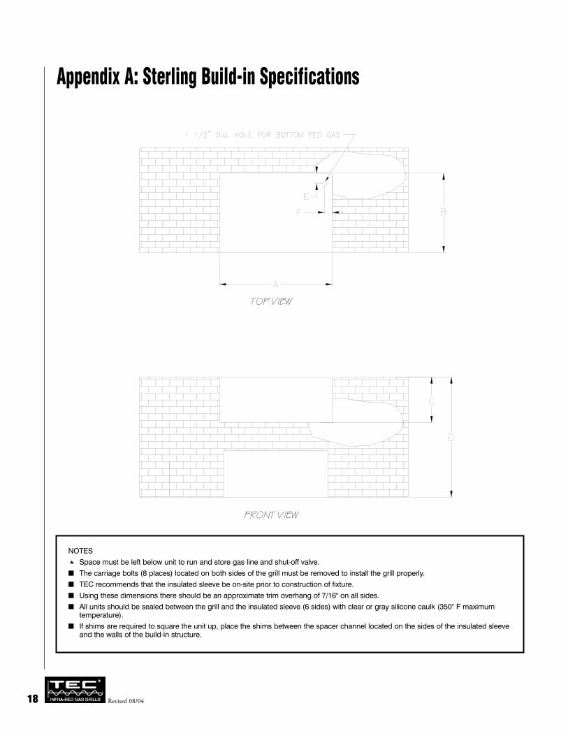
Appendix A: Sterling Build-in Specifications
NOTES
* Space must be left below unit to run and store gas line and shut-off valve.
■ The carriage bolts (8 places) located on both sides of the grill must be removed to install the grill properly.
■ TEC recommends that the insulated sleeve be on-site prior to construction of fixture.
■ Using these dimensions there should be an approximate trim overhang of 7/16" on all sides.
■ All units should be sealed between the grill and the insulated sleeve (6 sides) with clear or gray silicone caulk (350° F maximumtemperature).
■ If shims are required to square the unit up, place the shims between the spacer channel located on the sides of the insulated sleeveand the walls of the build-in structure.
Revised 08/0418
FRONT VIEW
TOP VIEW

1919
Appendix A: Sterling Build-in Specifications continued
SIDE VIEW

20 Revised 08/04
RotisserieCooking versatility is a trademark of the TEC grills.With the Rotisserie, you can add a new and excitingdimension to cooking. The Rotisserie can be used indirect Infra-red cooking or with the Bar-B-Que Tray (adeflector pan) for indirect Infra-red cooking.
Installing Rotisserie
Tools Required
■ 3/8" wrench
■ Flat head screwdriver
1. Attach the Rotisserie bracket to the stationary hoodwall with two (2) 10-32 x 1/2" screws and two (2)kep nuts (supplied).
2. Position the Rotisserie Motor on the RotisserieBracket and plug it into a grounded outlet.
Rotisserie UseCAUTION: DO NOT USE THE ROTISSERIE IN THE RAIN.
1. The Cooking Grids may be removed or left in place.
2. Follow the Burner Ignition procedures and operatethe grill for 5 minutes or until the ceramic burnersglow red.
3. Position the spit-rod in center of the meat, andtighten the forks into the ends of the meat. Makesure the meat is evenly balanced on the rod. Turn theRotisserie ON.
4. You may cook with the hood open or closed. If youclose the hood, do not turn the temperature uphigher than the*position indicated on the BurnerOutput Knobs, and monitor the food to ensure it isnot over cooking.
5. When you are finished cooking, be sure to turn bothburners to OFF.
For best results, refer to the Infra-red Cooking section ofthis manual.
The TEC Rotisserie has not been tested by CSA International.
Figure 18. Rotisserie
Appendix B: Accessories
20
ROTISSERIE

21
Bar-B-Que TrayThe primary purpose of the Bar-B-Que Tray is to deflectthe Infra-red heat so that it does not contact the fooddirectly. This permits slower cooking primarily with aconvection cooking process. It also catches excessdrippings and eliminates flare ups. You can use the Bar-B-Que Tray in conjunction with the Rotisserie for slowercooking and unique flavoring.
CAUTION: USING THE BAR-B-QUE TRAY ON HIGH
HEAT FOR A PROLONGED PERIOD OF TIME COULD
CAUSE BURNERS TO OVERHEAT.
Bar-B-Que Tray Use1. Remove both Cooking Grids.
2. Place the Bar-B-Que Tray in the grill, suspending itfrom side to side. Water or wine should be added tothe Bar-B-Que Tray to prevent it from warping.Repeat this process throughout the cooking processso that the liquid level is maintained. Be careful notto spill liquid onto the burners.
3. The Cooking Grids may be replaced or left out.
4. Follow the Burner Ignition procedures and operatethe grill for 5 minutes or until the ceramic burnersglow red.
5. Turn the Burner Output Knobs to the desiredtemperature.
6. For best results, close the Hood. If you close theHood, make sure the temperature is no higher thanthe *position indicated on the Burner OutputKnobs.
7. For lower heat, turn one burner to OFF and theother burner to LOW.
8. When you are finished cooking, be sure to turn allburners to OFF. Allow the grill and Bar-B-Que Trayto cool before attempting to remove the Bar-B-QueTray.
The TEC Bar-B-Que Tray has not been tested by CSA International.
Figure 19. Bar-B-Que Tray
Appendix B: Accessories continued
BAR-B-QUE TRAY

Wood Chip SmokerWith the Wood Chip Smoker, delicious smoked flavor can enhance your char-cooked foods. Damp hickory andmaple wood chips have been used to enhance the flavor of meat for years, but you can create your own flavors byusing various types of seasonings such as cloves, garlic orbay leaves.
Wood Chip Smoker Use1. Fill the Smoker with wood chips.
2. Add water and let the chips soak for at least 30minutes. For maximum flavor allow wood chips tosoak for several hours or overnight.
3. Drain the water from the Smoker.
4. Remove the Cooking Grids.
5. Place the Smoker above the front portion of burner.
6. Reposition the Cooking Grids.
7. Follow the Burner Ignition procedures and operate the grill for 5 minutes or until the ceramic burners turn red.
8. Turn the control dials to LOW.
9. For best results always close the Hood when using the Smoker. If you close the Hood, make sure thetemperature is no higher than the *position indicated on the Burner Output Knobs.
10. When you are finished cooking, be sure to turn allburners to OFF. Allow the grill and Smoker to coolbefore attempting to remove Smoker.
The TEC Wood Chip Smoker has not been tested by CSA International
Figure 20. Wood Chip Smoker
Appendix B: Accessories continued
22 Revised 08/04
SMOKER

Deep Fryer/SteamerThe Deep Fryer lets you cook foods that have beentraditionally limited to indoor cooking. It’s great forfrying chicken, french fries, shrimp or fish; or boilingcorn or potatoes and for cooking stews. .
To use this accessory on the RIGHT side of the unit,follow the procedures below. To use it on the LEFT side,reverse the references to LEFT and RIGHT.
Deep Fryer Use (Shown over RIGHT burner)
CAUTION: DO NOT CLOSE HOOD WHILE USING THIS
ATTACHMENT FOR FRYING. HOT COOKING OIL CAN
CAUSE BURNS. ALWAYS WEAR OVEN MITTS WHEN
USING THE DEEP FRYER AND USE EXTREME CAUTION
WHEN HANDLING HOT COOKING OIL OR WATER.
DO NOT OPERATE YOUR GRILL WITH THIS ACCESSORY
IN COMBINATION WITH OTHER ACCESSORIES, SUCH
AS THE FRYING GRIDDLE OR OTHER OBJECTS THAT
RESULT IN COVERING 75% OR MORE OF THE
REMAINING COOKING SURFACE. ALWAYS LEAVE AT
LEAST 25% OF THE SURFACE OPEN FOR VENTILATION.
OIL WILL BURN IF OVERHEATED. DO NOT LEAVE
UNATTENDED WHILE HEATING. IF SMOKING OCCURS,
REDUCE HEAT. IF OIL CATCHES FIRE, TURN OFF HEAT
AND EXTINGUISH WITH A CLASS A, B, C & D FIRE
EXTINGUISHER, OR COVER FRYER WITH STEAMER LID
UNTIL COOLED. DO NOT PUT WATER ON HOT OR
FLAMING OIL!
1. Remove the RIGHT Cooking Grid.
2. After removing the Steamer attachment, place theDeep Fryer over the RIGHT burner.
3. Fill the Deep Fryer one-third full with cooking oil orwater (one-gallon). DO NOT OVERFILL.
4. Follow the Burner Ignition procedures for the LEFTburner and operate the grill for 5 minutes or untilthe ceramic burner turns red.
5. After making certain the LEFT Burner is burningproperly, light the RIGHT burner. If you are notgoing to use the left burner, turn it to OFF.
6. Let the right burner stay on HIGH for 4 to 8minutes to properly heat cooking oil or water. Wesuggest you use a candy thermometer to check thetemperature of the oil or water. Normally, 350°F to375°F is sufficient for frying.
7. Turn RIGHT burner control dial between“medium” and LOW. Do not leave the right burneron HIGH.
8. Place the food into Deep Fryer with long-handledutensils.
9. After cooking, turn the burner(s) to OFF. Let thegrill and cooking oil or water cool to roomtemperature before attempting to remove the DeepFryer/Steamer.
The TEC Deep Fryer has not been tested by CSA International.
Figure 21. Deep Fryer (Shown over RIGHT burner)
23
Appendix B: Accessories continued
DEEP FRYER
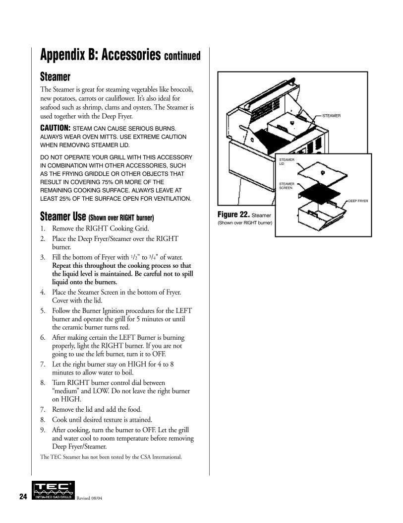
Steamer The Steamer is great for steaming vegetables like broccoli,new potatoes, carrots or cauliflower. It’s also ideal forseafood such as shrimp, clams and oysters. The Steamer isused together with the Deep Fryer.
CAUTION: STEAM CAN CAUSE SERIOUS BURNS.
ALWAYS WEAR OVEN MITTS. USE EXTREME CAUTION
WHEN REMOVING STEAMER LID.
DO NOT OPERATE YOUR GRILL WITH THIS ACCESSORY
IN COMBINATION WITH OTHER ACCESSORIES, SUCH
AS THE FRYING GRIDDLE OR OTHER OBJECTS THAT
RESULT IN COVERING 75% OR MORE OF THE
REMAINING COOKING SURFACE. ALWAYS LEAVE AT
LEAST 25% OF THE SURFACE OPEN FOR VENTILATION.
Steamer Use (Shown over RIGHT burner)
1. Remove the RIGHT Cooking Grid.
2. Place the Deep Fryer/Steamer over the RIGHTburner.
3. Fill the bottom of Fryer with 1/2" to 3/4" of water.Repeat this throughout the cooking process so thatthe liquid level is maintained. Be careful not to spillliquid onto the burners.
4. Place the Steamer Screen in the bottom of Fryer.Cover with the lid.
5. Follow the Burner Ignition procedures for the LEFTburner and operate the grill for 5 minutes or untilthe ceramic burner turns red.
6. After making certain the LEFT Burner is burningproperly, light the RIGHT burner. If you are notgoing to use the left burner, turn it to OFF.
7. Let the right burner stay on HIGH for 4 to 8minutes to allow water to boil.
8. Turn RIGHT burner control dial between“medium” and LOW. Do not leave the right burneron HIGH.
7. Remove the lid and add the food.
8. Cook until desired texture is attained.
9. After cooking, turn the burner to OFF. Let the grilland water cool to room temperature before removingDeep Fryer/Steamer.
The TEC Steamer has not been tested by the CSA International.
Figure 22. Steamer
(Shown over RIGHT burner)
24 Revised 08/04
Appendix B: Accessories continued
STEAMER
DEEP FRYER
STEAMER
SCREEN
STEAMER
LID
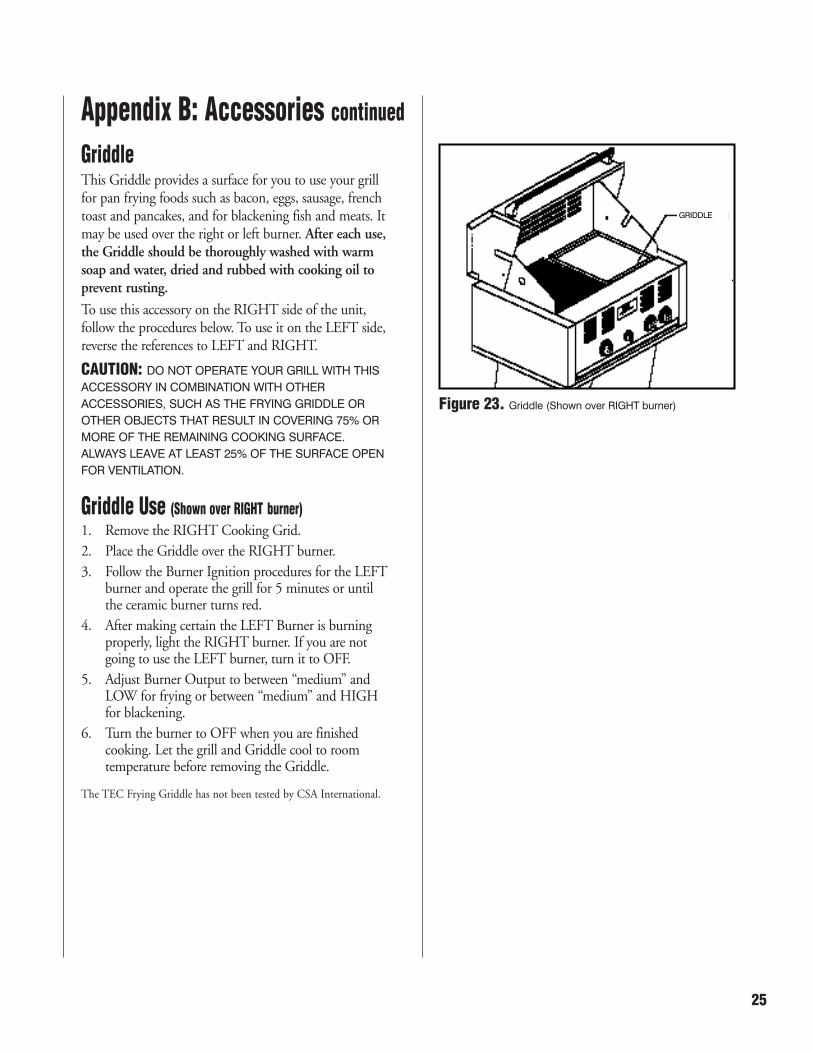
GriddleThis Griddle provides a surface for you to use your grillfor pan frying foods such as bacon, eggs, sausage, frenchtoast and pancakes, and for blackening fish and meats. Itmay be used over the right or left burner. After each use,the Griddle should be thoroughly washed with warmsoap and water, dried and rubbed with cooking oil toprevent rusting.
To use this accessory on the RIGHT side of the unit,follow the procedures below. To use it on the LEFT side,reverse the references to LEFT and RIGHT.
CAUTION: DO NOT OPERATE YOUR GRILL WITH THIS
ACCESSORY IN COMBINATION WITH OTHER
ACCESSORIES, SUCH AS THE FRYING GRIDDLE OR
OTHER OBJECTS THAT RESULT IN COVERING 75% OR
MORE OF THE REMAINING COOKING SURFACE.
ALWAYS LEAVE AT LEAST 25% OF THE SURFACE OPEN
FOR VENTILATION.
Griddle Use (Shown over RIGHT burner)
1. Remove the RIGHT Cooking Grid.
2. Place the Griddle over the RIGHT burner.
3. Follow the Burner Ignition procedures for the LEFTburner and operate the grill for 5 minutes or untilthe ceramic burner turns red.
4. After making certain the LEFT Burner is burningproperly, light the RIGHT burner. If you are notgoing to use the LEFT burner, turn it to OFF.
5. Adjust Burner Output to between “medium” andLOW for frying or between “medium” and HIGHfor blackening.
6. Turn the burner to OFF when you are finishedcooking. Let the grill and Griddle cool to roomtemperature before removing the Griddle.
The TEC Frying Griddle has not been tested by CSA International.
Figure 23. Griddle (Shown over RIGHT burner)
Appendix B: Accessories continued
25
GRIDDLE

WokEnjoy stir-fry cooking on your TEC grill with the Wokaccessory. Using high temperature, you can quickly cookchicken, beef, shrimp or assorted vegetables. After eachuse, the Wok should be thoroughly washed with soapand warm water and dried and rubbed with cooking oilto prevent rusting.
The Wok accessory may be used over the RIGHT orLEFT burners. To use this accessory on the RIGHT sideof the unit, follow the procedures below. To use it on theLEFT side, reverse the references to LEFT and RIGHT.
CAUTION: DO NOT OPERATE YOUR GRILL WITH THIS
ACCESSORY IN COMBINATION WITH OTHER
ACCESSORIES, SUCH AS THE FRYING GRIDDLE OR
OTHER OBJECTS THAT RESULT IN COVERING 75% OR
MORE OF THE REMAINING COOKING SURFACE.
ALWAYS LEAVE AT LEAST 25% OF THE SURFACE OPEN
FOR VENTILATION.
Wok Use (Shown over RIGHT burner)
1. Remove the RIGHT Cooking Grid.
2. Place the Wok support over the RIGHT burner.
3. Place the Wok in the Wok support.
4. After making certain the LEFT Burner is burningproperly, light the RIGHT burner. If you are notgoing to use the LEFT burner, turn it to OFF.
5. Adjust Burner Output to desired heat setting.
6. After cooking, make sure the burner is turned toOFF. Let the grill and Wok cool before attemptingto remove Wok.
The TEC Wok has not been tested by CSA International.
Figure 24. Wok
Appendix B: Accessories continued
26 Revised 08/04
WOK LID
WOK
WOK SUPPORT

Sterling® Side-burnerA Sterling® Side-burner allows you to have the versatilityof a cook-top attached to your gas grill. Sterling® Side-burner is available in Natural Gas or LP, and isconfigured for attachment to the RIGHT side only ofthe following Sterling® Gas Grills: SSG-40LSB, SSG-40NSB, SSG-60LSB and SSG-60NSB. Reference theSterling® Side-burner Owner’s Manual for additionalinstructions.
The Sterling® Side-burner has been tested and approved by CSAInternational.
Figure 25. Side-burner
Appendix B: Accessories continued
27

ORDER NO. DESCRIPTION
STBA ..............................................................Burner Assembly (less screen)
STBP ..............................................................Burner Head
STBS................................................................Burner Screen
STBCV............................................................Gas Valve, Burner
STPCV............................................................Gas Valve, Pilot
STBK ..............................................................Knob, Burner
STPK ..............................................................Knob, Pilot
STIK................................................................Knob, Igniter
STCG ..............................................................Cooking Grid, set of two
ST30DT (for Sterling II) ................................Drip Tray ....................................................ST43DT (for Sterling III)
ST30HH (for Sterling II)................................Hood Handle Kit ......................................ST43HH (for Sterling III)
ST30WR (for Sterling II)................................Baking Rack ..............................................ST43WR (for Sterling III)
ST30HS (for Sterling II) ................................Heat Shield..................................................ST43HS (for Sterling III)
REG26LP........................................................Regulator, w/ hose, LP gas
REGLP............................................................Regulator, LP gas (build-in applications)
REGNT ..........................................................Regulator, Natural gas (build-in applications)
ORI48 ............................................................Orifice, Natural gas, #48
ORI56 ............................................................Orifice, LP gas, #58
STIGN ............................................................Igniter
Appendix C: Replacement Parts
28 Revised 08/04

Appendix D: Troubleshooting
PROBABLE CAUSEa. Lack of gas
b. Obstruction in pilot orifice
c. Defective piezo igniter
d. Dirty ignition electrode
PROBLEMPilot will not light
REMEDYa. After turning Pilot Output Knob to ON
position, wait approximately 20-30 seconds forair to purge gas supply line before turningIgniter Knob. Fill LP gas cylinder, if applicable.Adjust pilot following the Pilot FlameAdjustment procedures outlined on Page 13.
b. Clean pilot orifice
c. Replace piezo igniter
d. Clean pilot electrode
Burner output at HIGHsetting is too low. (Rumblingnoise and fluttering blue flameat burner surface.)
a. Lack of gas
b. Kinked regulator hose.
c. Insufficient gas pressure despiteample gas supply.
d. Dirty or clogged orifice.
e. Venturi tube obstructed by spiderwebs, wasp nest, or other foreignmatter.
f. Cracked burner.
a. Check gas level in LP gas cylinder, ifapplicable.
b. Reposition regulator hose, as necessary.
c. Adjust regulator, as necessary.
d. Clean burner orifice.
e. Clean out all obstructions from venturi tubes.
f. Contact TEC Authorized Dealer. Replaceceramic burner head.
Burner output at LOW settingis too hot (or too cool).
a. Low heat setting is adjusted too high(or too low).
a. Reduce (or increase) low heat setting followingprocedures on Page 12.
Burner backfires (duringoperation burner abruptlymakes a loud “woosh” sound,followed by a continuousblow-torch type sound andgrow dim).
a. Overloaded with grease drippings orbuild-up, clogging ports.
b. Burner overheated due to inadequateventilation (too much cookingsurface covered or operation of grillon high fire with hood closed).
c. Cracked ceramic.
d. None of the above. Probable cause isleak in packing within or underceramic burner head. Also can occurthrough breaks in welds of burnerbox. Both are manufacturer’s defectsto which your warranty applies.
In all cases turn Burner Output Knob to OFFposition and let it cool for at lease twominutes. Then:
a. Relight burner and burn at a HIGH settingfor at least five minutes or until ceramicuniformly glows red.
b. Remove any object or accessories which maybe covering more than 75% of the cookingservice. Allow the burner to cool forapproximately two minutes, then relight theburner. DO NOT OPERATE THE GRILLON HIGH FIRE WITH HOOD CLOSED.
c. Allow burner to cool and inspect very closelyfor cracks (which may be nearly invisible). Ifcracks are found, contact TEC AuthorizedDealer to replace burner head.
d. Contact TEC Authorized Dealer. Packingunder burner head should be replaced. Ifbackfiring continues, burner box welds shouldbe inspected for holes and/or burner headshould be replaced.
29

Notes
30 Revised 08/04