Step by Step Guide - SKC Ltd€¦ · Step by Step Guide An Introduction to Air Sampling Sidekick...
20
www.skcltd.com Step by Step Guide An Introduction to Air Sampling Sidekick Pump
Transcript of Step by Step Guide - SKC Ltd€¦ · Step by Step Guide An Introduction to Air Sampling Sidekick...

www.skcltd.com
Step by Step Guide
An Introduction to Air Sampling
Sidekick Pump

Page 2 224-G2 Issue D www.skcltd.com
The Sidekick Air Sampling Pump .......................................................................................................................1
The I.O.M. Sampler ...........................................................................................................................................2
Inhalable Dust Sampling using the I.O.M. Sampler .............................................................................................3
Respirable Dust Sampling using the Cyclone Sampler .......................................................................................6
Gas & Vapour Sampling using Sorbent Tubes ..................................................................................................10
Gas & Vapour Sampling using Impingers .........................................................................................................13
Bag Sampling using the Sidekick Pump ..........................................................................................................15
The Sample Train .............................................................................................................................................16
Sample Train Check List ..................................................................................................................................16
A helping hand from the expertsThis guide is designed as an introduction to the basic principles of air sampling methods. The advice in this guide deals with the setting up of equipment only.
Advice notes relating to specific sampling methods can be obtained from the HSE (www.hse.gov.uk) and these will give you a good understanding of the approach you should take to sampling in your particular industry.
As an expert in the field of air sampling, SKC believe in supporting customers every step of the way, so in addition to the Step By Step guides there is a range of training seminars available to help you get the best from your sampling equipment.
If you are new to air sampling, our one day seminar 'A Practical Course in Air Monitoring' will give you the help you need to get started.
The course includes both theoretical and practical sessions in the use of air sampling equipment. An experienced practitioner will offer valuable input on sampling strategy and will assist with instrument configuration and calibration. You will soon have everything you need to formulate a professional monitoring programme.
Contact SKC Limited customer services today for details on courses and available dates:
T: +44 (0) 1258 480188
W: www.skcltd.com
Contents
www.skcltd.com 224-G2 Issue D Page 1
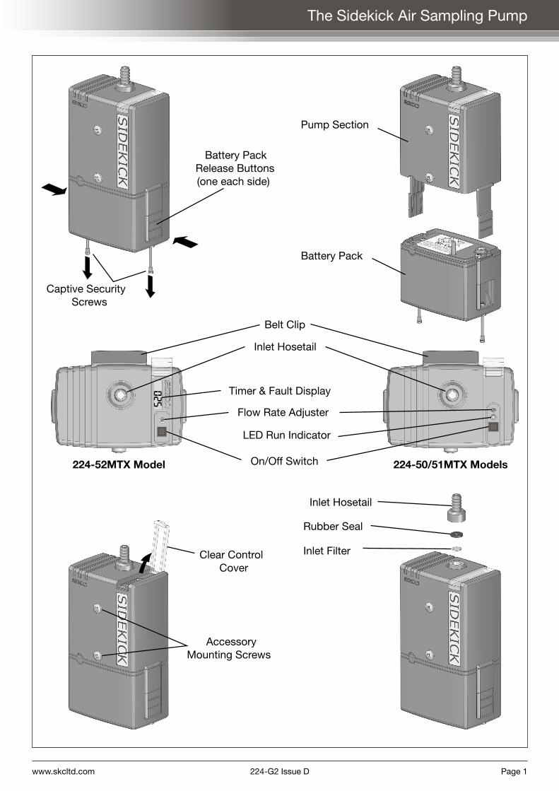
The Sidekick Air Sampling Pump
Captive SecurityScrews
Battery PackRelease Buttons(one each side)
Pump Section
Battery Pack
224-52MTX Model 224-50/51MTX Models
Belt Clip
Timer & Fault Display
Inlet Hosetail
Flow Rate Adjuster
LED Run Indicator
On/Off Switch
Clear ControlCover
AccessoryMounting Screws
Inlet Hosetail
Rubber Seal
Inlet Filter
Page 2 224-G2 Issue D www.skcltd.com
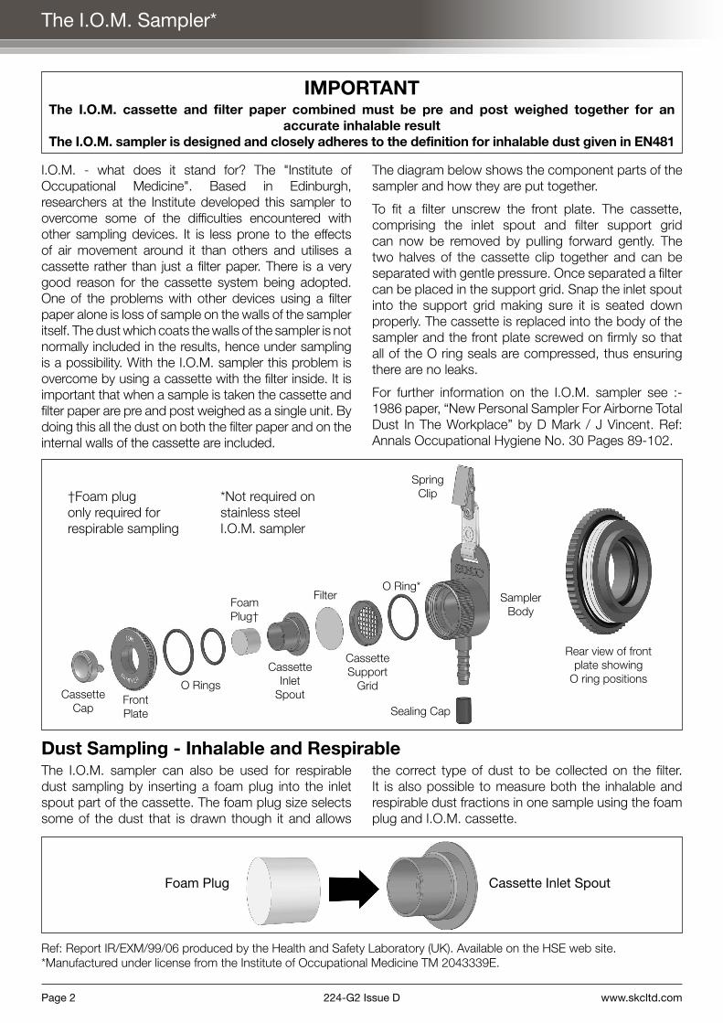
The I.O.M. Sampler*
IMPORTANTThe I.O.M. cassette and filter paper combined must be pre and post weighed together for an
accurate inhalable resultThe I.O.M. sampler is designed and closely adheres to the definition for inhalable dust given in EN481
I.O.M. - what does it stand for? The "Institute of Occupational Medicine". Based in Edinburgh, researchers at the Institute developed this sampler to overcome some of the difficulties encountered with other sampling devices. It is less prone to the effects of air movement around it than others and utilises a cassette rather than just a filter paper. There is a very good reason for the cassette system being adopted. One of the problems with other devices using a filter paper alone is loss of sample on the walls of the sampler itself. The dust which coats the walls of the sampler is not normally included in the results, hence under sampling is a possibility. With the I.O.M. sampler this problem is overcome by using a cassette with the filter inside. It is important that when a sample is taken the cassette and filter paper are pre and post weighed as a single unit. By doing this all the dust on both the filter paper and on the internal walls of the cassette are included.
The diagram below shows the component parts of the sampler and how they are put together.
To fit a filter unscrew the front plate. The cassette, comprising the inlet spout and filter support grid can now be removed by pulling forward gently. The two halves of the cassette clip together and can be separated with gentle pressure. Once separated a filter can be placed in the support grid. Snap the inlet spout into the support grid making sure it is seated down properly. The cassette is replaced into the body of the sampler and the front plate screwed on firmly so that all of the O ring seals are compressed, thus ensuring there are no leaks.
For further information on the I.O.M. sampler see :- 1986 paper, “New Personal Sampler For Airborne Total Dust In The Workplace” by D Mark / J Vincent. Ref: Annals Occupational Hygiene No. 30 Pages 89-102.
The I.O.M. sampler can also be used for respirable dust sampling by inserting a foam plug into the inlet spout part of the cassette. The foam plug size selects some of the dust that is drawn though it and allows
the correct type of dust to be collected on the filter. It is also possible to measure both the inhalable and respirable dust fractions in one sample using the foam plug and I.O.M. cassette.
Dust Sampling - Inhalable and Respirable
Ref: Report IR/EXM/99/06 produced by the Health and Safety Laboratory (UK). Available on the HSE web site.*Manufactured under license from the Institute of Occupational Medicine TM 2043339E.
Foam Plug Cassette Inlet Spout
CassetteCap
FrontPlate
O Rings
CassetteInlet
Spout
Filter
Cassette Support
Grid
O Ring*Sampler
Body
Sealing Cap
Foam Plug†
Spring Clip†Foam plug
only required for respirable sampling
*Not required on stainless steel I.O.M. sampler
Rear view of front plate showing
O ring positions
www.skcltd.com 224-G2 Issue D Page 3
Inhalable Dust Sampling using the I.O.M. Sampler
For information on using the I.O.M. sampler for respirable dust fractionsplease contact SKC customer support on +44 (0) 1258 480188
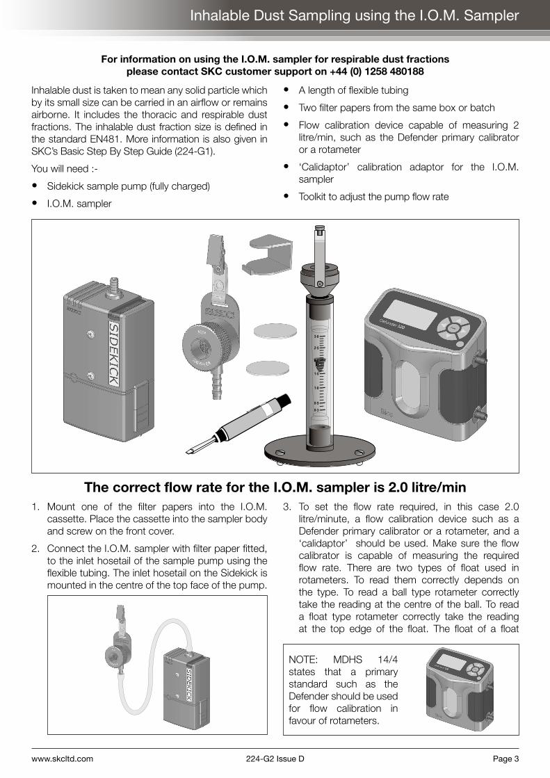
1. Mount one of the filter papers into the I.O.M. cassette. Place the cassette into the sampler body and screw on the front cover.
2. Connect the I.O.M. sampler with filter paper fitted, to the inlet hosetail of the sample pump using the flexible tubing. The inlet hosetail on the Sidekick is mounted in the centre of the top face of the pump.
3. To set the flow rate required, in this case 2.0 litre/minute, a flow calibration device such as a Defender primary calibrator or a rotameter, and a ‘calidaptor’ should be used. Make sure the flow calibrator is capable of measuring the required flow rate. There are two types of float used in rotameters. To read them correctly depends on the type. To read a ball type rotameter correctly take the reading at the centre of the ball. To read a float type rotameter correctly take the reading at the top edge of the float. The float of a float
0
5
0
5
0
5
3
3
2
2
1
1
0
0
The correct flow rate for the I.O.M. sampler is 2.0 litre/min
Inhalable dust is taken to mean any solid particle which by its small size can be carried in an airflow or remains airborne. It includes the thoracic and respirable dust fractions. The inhalable dust fraction size is defined in the standard EN481. More information is also given in SKC’s Basic Step By Step Guide (224-G1).
You will need :-
• Sidekick sample pump (fully charged)
• I.O.M. sampler
• A length of flexible tubing
• Two filter papers from the same box or batch
• Flow calibration device capable of measuring 2 litre/min, such as the Defender primary calibrator or a rotameter
• ‘Calidaptor’ calibration adaptor for the I.O.M. sampler
• Toolkit to adjust the pump flow rate
NOTE: MDHS 14/4 states that a primary standard such as the Defender should be used for flow calibration in favour of rotameters.
Page 4 224-G2 Issue D www.skcltd.com
Inhalable Dust Sampling using the I.O.M. Sampler
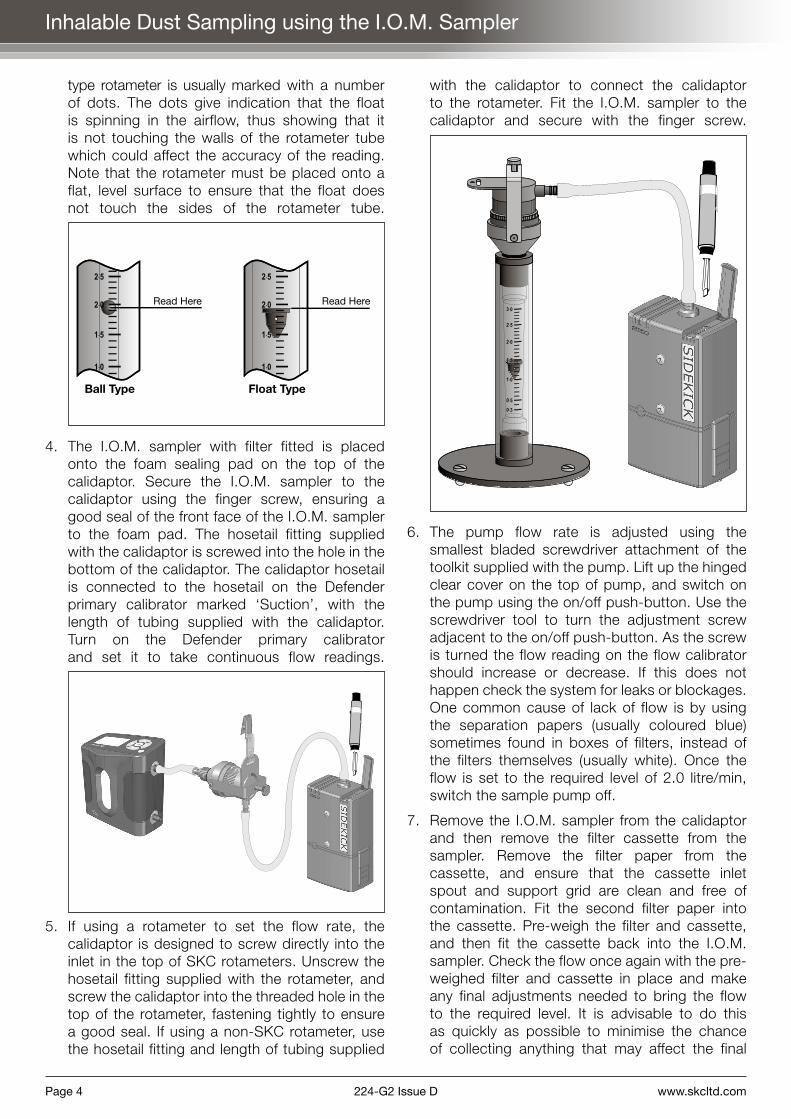
type rotameter is usually marked with a number of dots. The dots give indication that the float is spinning in the airflow, thus showing that it is not touching the walls of the rotameter tube which could affect the accuracy of the reading. Note that the rotameter must be placed onto a flat, level surface to ensure that the float does not touch the sides of the rotameter tube.
2
2
1
1
5
0
5
0
2
2
1
1
5
0
5
0
Read Here Read Here
Ball Type Float Type
4. The I.O.M. sampler with filter fitted is placed onto the foam sealing pad on the top of the calidaptor. Secure the I.O.M. sampler to the calidaptor using the finger screw, ensuring a good seal of the front face of the I.O.M. sampler to the foam pad. The hosetail fitting supplied with the calidaptor is screwed into the hole in the bottom of the calidaptor. The calidaptor hosetail is connected to the hosetail on the Defender primary calibrator marked ‘Suction’, with the length of tubing supplied with the calidaptor. Turn on the Defender primary calibrator and set it to take continuous flow readings.
5. If using a rotameter to set the flow rate, the calidaptor is designed to screw directly into the inlet in the top of SKC rotameters. Unscrew the hosetail fitting supplied with the rotameter, and screw the calidaptor into the threaded hole in the top of the rotameter, fastening tightly to ensure a good seal. If using a non-SKC rotameter, use the hosetail fitting and length of tubing supplied
with the calidaptor to connect the calidaptor to the rotameter. Fit the I.O.M. sampler to the calidaptor and secure with the finger screw.
0
5
0
5
0
5
3
3
2
2
1
1
0
0
6. The pump flow rate is adjusted using the smallest bladed screwdriver attachment of the toolkit supplied with the pump. Lift up the hinged clear cover on the top of pump, and switch on the pump using the on/off push-button. Use the screwdriver tool to turn the adjustment screw adjacent to the on/off push-button. As the screw is turned the flow reading on the flow calibrator should increase or decrease. If this does not happen check the system for leaks or blockages. One common cause of lack of flow is by using the separation papers (usually coloured blue) sometimes found in boxes of filters, instead of the filters themselves (usually white). Once the flow is set to the required level of 2.0 litre/min, switch the sample pump off.
7. Remove the I.O.M. sampler from the calidaptor and then remove the filter cassette from the sampler. Remove the filter paper from the cassette, and ensure that the cassette inlet spout and support grid are clean and free of contamination. Fit the second filter paper into the cassette. Pre-weigh the filter and cassette, and then fit the cassette back into the I.O.M. sampler. Check the flow once again with the pre-weighed filter and cassette in place and make any final adjustments needed to bring the flow to the required level. It is advisable to do this as quickly as possible to minimise the chance of collecting anything that may affect the final

www.skcltd.com 224-G2 Issue D Page 5
Inhalable Dust Sampling using the I.O.M. Sampler
result. The I.O.M. sampler complete with the new filter should now be fitted with the cassette cover supplied, and is ready to take into the workplace.
Filter used forcalibration
New filterfor sample
8. Mount the sample train (comprising the sample pump, tubing and I.O.M. sampler) onto the worker who is to wear it during the sample. The I.O.M. sampler should be mounted as close to the breathing zone as is practical and comfortable. The pump can either be clipped to a belt or placed into a pouch. Note that the connecting tube can present a hazard if left to flap around, in much the same way as a necktie. Measures should be taken to protect the wearer by clipping or restraining the tube so that it cannot become caught up in anything.
30cmDiameterBreathing
Zone
I.O.M.Sampler
Pump
Once the pump is mounted on the worker in a satisfactory way, remove the cassette
cover and switch on the pump. IMPORTANT: The start time of the sample should be noted.
9. At the end of the sample switch off the pump, replace the cassette cover and note the finish time of the sample. Remove the sample train from the worker, and once away from the sample location re-check the flow rate of the sample pump (as per MDHS14/4). Ensure that the flow rate check is carried out as quickly as possible to minimise the chance of collecting anything that may affect the final result. Remove the filter cassette from the I.O.M. sampler and post weigh the filter and cassette. If the sample is to be sent to a laboratory for further analysis, refit the cassette cover and fit a cassette clip.
The start and finish times, sample duration, worker’s name, start and finish flow rates pre and post sample weights and any other relevant details of the sample should be noted down and indexed to the filter paper or cassette by number or code.

Page 6 224-G2 Issue D www.skcltd.com
Respirable Dust Sampling using the Cyclone Sampler
Respirable dust is taken to be solid particles which, because of their extremely small size, can be drawn deep into the lungs, and are not ejected by the normal means of breathing out, coughing or travelling out in the lung mucus. It is because of this ability to stay in the body that it is considered to be dangerous. Dust of this small size is normally invisible to the human eye. The respirable dust fraction size is defined in the standard EN481. More information is also given in SKC's Basic Step By Step Guide (224-G1).
You will need :-
• Sidekick sample pump (fully charged)
• Cyclone sampler and cassette
• A length of flexible tubing
• Filter paper and pre-weighed filter paper from the same box or batch
• Flow calibration device capable of measuring 2.2 litre/min, such as the Defender primary calibrator or a rotameter
• Toolkit to adjust the pump flow rate
• Filter transport cassette
0
5
0
5
0
5
3
3
2
2
1
1
0
0
The correct flow rate for the cyclone sampler is 2.2 litre/min1. Mount the filter paper that is not pre-weighed into
the cyclone cassette as shown below. The easiest way to place the filter in the cassette is as follows.
Cassette top
Filter support grid
Filter
Cassette bottom
Remove the top half of the cassette and place it upside down on a flat surface, so that it looks like a shallow bowl. Place the filter support grid into the cassette top and place the filter on the grid. Carefully pick up the cassette top with grid and filter, and snap the cassette bottom onto the cassette top. By assembling the filter cassette in this way the filter remains located centrally on the support grid.
2. Place the filter cassette into the cyclone sampler body, mounting it with the embossed text 'SKC TOP' facing upwards as shown in the figure to the right. Check that an O ring is fitted into the circular slot in the bottom face of the sampler top, fit the sampler top over the cassette and secure with the retaining ring, tightening firmly to ensure a good seal. Make sure a grit pot is

www.skcltd.com 224-G2 Issue D Page 7
Respirable Dust Sampling using the Cyclone Sampler
fitted to the bottom of the cyclone sampler.
Grit Pot
SamplerBody
FilterCassette
AirInlet
AirOutlet
SamplerTop
RetainingRing
3. Connect the top tubing connector (air outlet) on the cyclone sampler to the inlet hosetail on the top of the sample pump using the length of flexible tubing.
4. To set the flow rate required, in this case 2.2 litre/minute, a flow calibration device such as a Defender primary calibrator or a rotameter should be used. Make sure the flow calibrator is capable of measuring the required flow rate. There are two types of float used in rotameters. To read them correctly depends on the type. To read a ball type rotameter correctly take the reading at the centre of the ball. To read a float type rotameter correctly take the reading at the top edge of the float. Refer to the figure below. The float of a float type rotameter is usually marked with a number of dots. The dots give indication that the float is spinning in the airflow, thus showing that the float is not touching the walls of the rotameter tube which could affect the accuracy of the reading. Note that the rotameter must be placed onto a flat, level surface to ensure that the float does not touch the sides of the rotameter tube.
2
2
1
1
5
0
5
0
2
2
1
1
5
0
5
0
Read Here Read Here
Ball Type Float Type
5. Connect the air inlet of the cyclone sampler to the hosetail on the Defender primary calibrator marked 'Suction', with a length of
Page 8 224-G2 Issue D www.skcltd.com
Respirable Dust Sampling using the Cyclone Sampler
tubing. Turn on the Defender primary calibrator and set it to take continuous flow readings.
6. If using a rotameter to set the flow rate, connect the air inlet of the cyclone sampler to the hosetail on the top of the rotameter using a length of tubing. If a 'calidaptor' is fitted to the rotameter, screw the threaded hosetail fitting supplied with the calidaptor into the threaded hole in the bottom of the calidaptor 'bowl', and connect the cyclone sampler air inlet to the hosetail.
0
5
0
5
0
5
3
3
2
2
1
1
0
0
Calidaptor(if fitted torotameter)
Hosetail
7. The pump flow rate is adjusted using the smallest bladed screwdriver attachment of the toolkit supplied with the pump. Lift up the hinged clear cover on the top of pump, and switch on the pump using the on/off push-button. Use the screwdriver tool to turn the adjustment screw adjacent to the on/off push-button. As the screw is turned the flow reading on the flow calibrator should increase or decrease. If this does not happen check the system for leaks or blockages. One common cause of lack of flow is by using the separation papers (usually coloured blue) sometimes found in boxes of filters instead of the filters themselves (usually white). Once the flow is set to the required level of 2.2 litre/min switch the sample pump off.
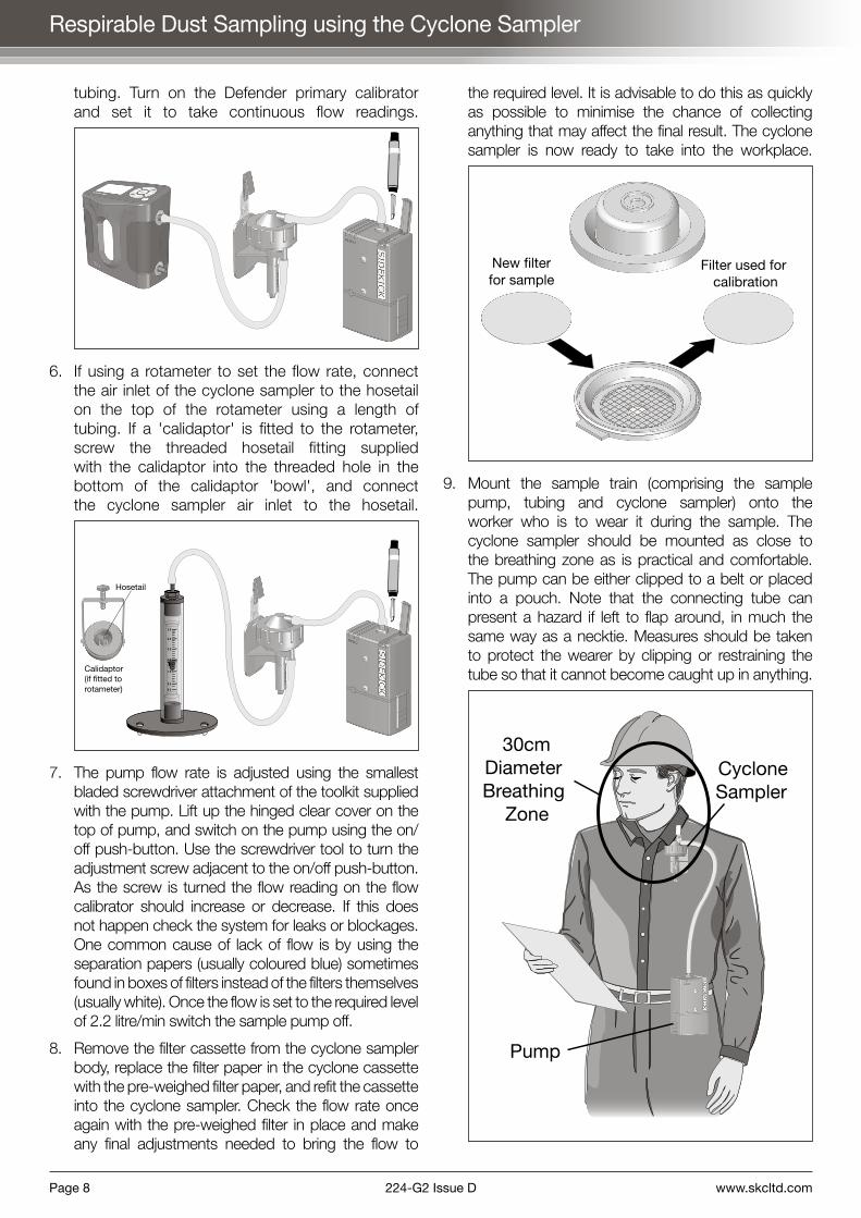
8. Remove the filter cassette from the cyclone sampler body, replace the filter paper in the cyclone cassette with the pre-weighed filter paper, and refit the cassette into the cyclone sampler. Check the flow rate once again with the pre-weighed filter in place and make any final adjustments needed to bring the flow to
the required level. It is advisable to do this as quickly as possible to minimise the chance of collecting anything that may affect the final result. The cyclone sampler is now ready to take into the workplace.
New filterfor sample
Filter used forcalibration
9. Mount the sample train (comprising the sample pump, tubing and cyclone sampler) onto the worker who is to wear it during the sample. The cyclone sampler should be mounted as close to the breathing zone as is practical and comfortable. The pump can be either clipped to a belt or placed into a pouch. Note that the connecting tube can present a hazard if left to flap around, in much the same way as a necktie. Measures should be taken to protect the wearer by clipping or restraining the tube so that it cannot become caught up in anything.
30cmDiameterBreathing
Zone
CycloneSampler
Pump

www.skcltd.com 224-G2 Issue D Page 9
Respirable Dust Sampling using the Cyclone Sampler
Once the pump is mounted on the worker in a satisfactory way it can be switched on. IMPORTANT: The start time of the sample should be noted.
10. At the end of the sample switch the pump off and note the finish time of the sample. Remove the sample train from the worker, and once away from the sample location re-check the flow rate of the sample pump (as per MDHS14/4). Ensure that the flow rate check is carried out as quickly as possible to minimise the chance of collecting anything that may affect the final result. Remove the filter cassette from the cyclone sampler. Open the filter cassette, carefully lift out the filter and post weigh it. If the sample is to be sent to a laboratory for further analysis, carefully transfer the filter onto the support grid in a transport cassette and snap the transport cassette shut.
The start and finish times, sample duration, worker's name, start and finish flow rates, pre and post sample weights and other relevant details of the sample should be noted down and indexed to the filter paper by number or code.

Page 10 224-G2 Issue D www.skcltd.com
Gas & Vapour Sampling using Sorbent Tubes
You will need :-
• Sidekick sample pump (fully charged)
• Constant pressure controller (CPC)
• Low flow adaptor (tube holder)
• Tube cover of appropriate size for the sorbent tube being used
• A length of flexible tubing
• Tube adaptor for small diameter sorbent tubes (SKC part no. 717-511)
• Two sorbent tubes from the same box or batch
• Flow calibration device capable of measuring the intended flow rate, typically between 5 and 500 ml/min, such as the Defender primary calibrator
• Toolkit to adjust the flow rate
1. Connect the flow calibrator directly to the sample pump inlet hosetail using the length of tubing. Turn on the pump and adjust the flow rate to 1.5 litre/minute.
This is the required flow rate for correct operation of the constant pressure controller (CPC). Switch off the pump and disconnect the flow calibrator. No further adjustment of the pump flow rate should be made.
2. Connect the CPC unit to the pump. The short length of tube already attached to the
CPC is connected to the pump inlet hosetail. This now puts the pump into the low flow mode and allows use of the low flow adaptor.
Low FlowAdaptor
ConstantPressureController(CPC)
The combined low flow adaptor and tube holder is now connected to the free end of the CPC using the length of tubing. As a further check that the connections are correct, the labelled side of

www.skcltd.com 224-G2 Issue D Page 11
Gas & Vapour Sampling using Sorbent Tubes
the CPC should be on the side connected to the low flow adaptor and tube holder.
3. Take one of the sorbent tubes and break off both ends, ideally using a purpose designed tube tip breaker. Take care handling the tube as the broken ends are extremely sharp. Fit the sorbent tube into the short black hose of the low flow adaptor.
To determine the correct way the sorbent tube should face, look for a printed arrow on the tube. If present the arrow should point towards the pump. The arrow represents the correct direction of the airflow through the tube. If there is no arrow on the tube, the largest air gap or unfilled section of the tube should face away from the pump, that is, to atmosphere.
4. With the sorbent tube in place in the low flow adaptor a connection from the free end of the sorbent tube is made to the hosetail on the Defender flow calibrator marked 'Suction', as shown.
Tube adaptor for smalldiameter sorbent tubes
For small diameter sorbent tubes use the tube adaptor to make the connection to the free end of the sorbent tube. Switch on the pump and flow calibrator, and set the calibrator to take continuous readings. Ensure that the sorbent tube is held vertically during calibration. Adjust the air flow rate through the sorbent tube by turning the throttle valve screw in the side of the low flow adaptor using the large bladed screwdriver attachment of the toolkit, as shown above. Once the flow rate is set to the required level (depending on tube type and sampling method), switch off the pump.
5. The sorbent tube used to set the flow rate is now removed from the tube holder and replaced with a clean tube with both ends broken off. The exposed end of the tube should be protected with the tube cover, which screws onto the low flow adaptor. One of the red plastic caps provided can be used to seal the sorbent tube until the sample is taken, however please note that the cap should not be pressed on too far as they are designed to provide an airtight seal for transportation. Once pushed fully home the caps require cutting off with a sharp knife.
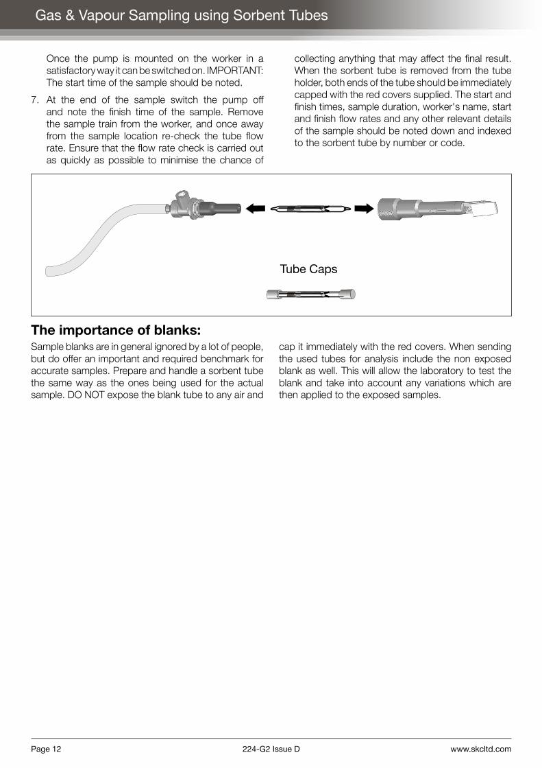
Tube Cap
Tube Cover
6. Mount the sample train (comprising the sample pump, tubing, tube holder and tube cover) onto the worker who is to wear it during the sample. The tube holder should be mounted vertically on the worker, and as close to the breathing zone as is practical and comfortable. The pump can be either clipped to a belt or placed into a pouch. Note that the connecting tube can present a hazard if left to flap around, in much the same way as a necktie. Measures should be taken to protect the wearer by clipping or restraining the tube so that it cannot become caught up in anything.
30cmDiameterBreathing
Zone
Page 12 224-G2 Issue D www.skcltd.com
Gas & Vapour Sampling using Sorbent Tubes
Once the pump is mounted on the worker in a satisfactory way it can be switched on. IMPORTANT: The start time of the sample should be noted.
7. At the end of the sample switch the pump off and note the finish time of the sample. Remove the sample train from the worker, and once away from the sample location re-check the tube flow rate. Ensure that the flow rate check is carried out as quickly as possible to minimise the chance of
collecting anything that may affect the final result. When the sorbent tube is removed from the tube holder, both ends of the tube should be immediately capped with the red covers supplied. The start and finish times, sample duration, worker's name, start and finish flow rates and any other relevant details of the sample should be noted down and indexed to the sorbent tube by number or code.
The importance of blanks:Sample blanks are in general ignored by a lot of people, but do offer an important and required benchmark for accurate samples. Prepare and handle a sorbent tube the same way as the ones being used for the actual sample. DO NOT expose the blank tube to any air and
cap it immediately with the red covers. When sending the used tubes for analysis include the non exposed blank as well. This will allow the laboratory to test the blank and take into account any variations which are then applied to the exposed samples.
Tube Caps
www.skcltd.com 224-G2 Issue D Page 13
Gas & Vapour Sampling using Impingers
Impingers are typically run at a low flow rate of 1.0 litre/minute. It must first be decided if you are going to carry out personal or static sampling. If personal sampling is the method adopted you will require an impinger pouch and an in-line trap. If static sampling is more suited an impinger bracket and glass trap should be used.
Note: Although personal sampling is recommended by the HSE and the limits in EH 40 are based on personal exposure, some thought must be given to the fact that placing glassware filled with, in some cases, hazardous liquids does present a hazard in itself. It may, in your opinion, be safer to take samples on a static basis.
The following section describes how to sample with impingers on a STATIC basis at a flow rate of 1.0 litre/minute. If you plan to sample on a personal basis use an in-line trap and a pouch to attach to a subject. Details shown in the text on personal sampling are identified in italics and contained in brackets.
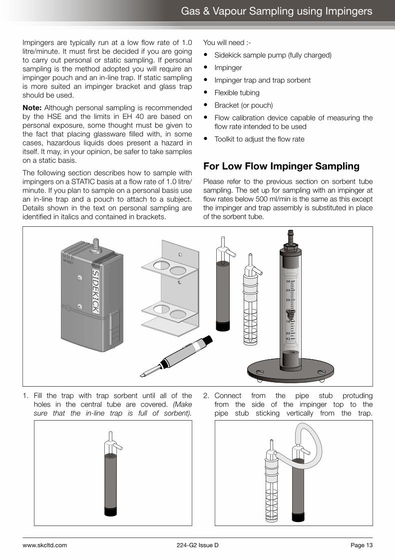
You will need :-
• Sidekick sample pump (fully charged)
• Impinger
• Impinger trap and trap sorbent
• Flexible tubing
• Bracket (or pouch)
• Flow calibration device capable of measuring the flow rate intended to be used
• Toolkit to adjust the flow rate
For Low Flow Impinger SamplingPlease refer to the previous section on sorbent tube sampling. The set up for sampling with an impinger at flow rates below 500 ml/min is the same as this except the impinger and trap assembly is substituted in place of the sorbent tube.
0
5
0
5
0
5
3
3
2
2
1
1
0
0
1. Fill the trap with trap sorbent until all of the holes in the central tube are covered. (Make sure that the in-line trap is full of sorbent).
2. Connect from the pipe stub protuding from the side of the impinger top to the pipe stub sticking vertically from the trap.

Page 14 224-G2 Issue D www.skcltd.com
(Connect from the impinger to the in-line trap with a length of flexible tubing. It does not matter which way around the in-line trap is connected).
3. Fasten the bracket to the front of the Sidekick pump using the two screws supplied with the pump. Place the trap and the impinger into the bracket. (Place the impinger and in-line trap on a suitable surface).
4. Remove the top of the impinger and fill it to the desired level with some of the liquid intended to be used for the sample. Connect with flexible tubing between the sample pump inlet hosetail and the pipe stub protuding from the side of the trap.
5. It is important to make sure that the sample pump is set to 1.0 litre/minute BEFORE switching it on. If the pump is set to a higher flow rate the liquid contained in the impinger may well be sucked out and into the trap or pump. Connect with a length of tubing between the impinger and a calibration device. Using the toolkit, adjust the flow adjuster screw on the pump adjacent to the on/off push-button. As the screw is turned the flow reading should increase or decrease. If this does not happen check the system for leaks or blockages. Once the flow rate is set to the required level switch the sample pump off.
0
5
0
5
0
5
3
3
2
2
1
1
0
0
6. Renew the liquid in the impinger, filling to the correct level as advised in the method you are following. The complete unit can now be placed in the work place and switched on.
(Mount the sample train [comprising the sample pump, tubing, sorbent trap, impinger and pouch] onto the worker who is to wear it during the sample. A length of tube should be run from the impinger to a position as close to the breathing zone as is practical and comfortable. The pump can be either clipped to a belt or placed into a pouch. Note that the connecting tube can present a hazard if left to flap around, in much the same way as a necktie. Measures should be taken to protect the wearer by clipping or restraining the tube so that it cannot become caught up in anything. Once the pump is mounted to the worker in a satisfactory way it can be switched on).
30cmDiameterBreathing
Zone
Impinger& Pouch
Pump
Trap
IMPORTANT: The start time of the sample should be noted.
7. As the liquid can evaporate quite quickly the impinger should be checked every 30-45 minutes and topped up with liquid to ensure the end of the vertical glass tube inside is always covered with liquid.
8. At the end of the sample switch the pump off, and note the finish time. Check the flow rate at the end of the sample. The start and finish times, sample duration, start and finish flow rates and any other relevant details of the sample should be noted down and indexed to the impinger by number or code.
Gas & Vapour Sampling using Impingers

www.skcltd.com 224-G2 Issue D Page 15
Bag Sampling using the Sidekick Pump
Where there is a need for the sample not to come into contact with the pump or where the atmosphere may be aggressive (as found with stack sampling) a method of collection using an intermediate vessel is recommended. The intermediate vessel can be any container of adequate size that is air tight. For example, the SKC Vac-U-Chamber. Some people use large Tupperware containers if the bags are small, but any air tight vessel, metal, plastic or otherwise can be used.
You will need :-
• Sidekick sample pump (fully charged)
• Sample bag of required size
• Vac-U-Chamber or container of adequate size
• Two air tight fittings for lid of container
• Calibration device that is capable of measuring the desired flow rate
• Toolkit to adjust the flow rate
Please note: The container must be of a large size in comparison with the sample bag otherwise too much back pressure is imposed on the pump.
The set up is as shown in the figure below.
A container is prepared by placing two air tight fittings in the lid, one is for the suction from the pump, the other is to supply the sample bag with the sampled air. By turning the pump on, air inside the container
is drawn out producing a negative pressure inside the container. In order to maintain pressure equilibrium inside the container, air is now drawn into the sample bag via the tube to atmosphere.
1. Before placing the bag into the container open its valve. Pinch closed the tube from the bag to atmosphere (or sample point) at a point outside the container.
2. Place the bag into the container and close the lid.
3. When ready to take the sample remove the clamp from the tube running from the bag to atmosphere.
4. Switch on the pump.
5. When the sample has been taken switch off the pump and re-clamp the tube running from the bag to atmosphere.
6. Remove the bag from the container and close the valve. The tube from the bag can now be removed without loss of sampled air.
There is no way in which the volume taken into the bag by this method can be accurately determined, unless some kind of calibration device is fitted in-line from the bag to atmosphere. An estimated volume can be obtained from the flow rate of the pump multiplied by the run time. This should not, however, be used to produce accurate results of concentration of contaminants.
Page 16 224-G2 Issue D www.skcltd.com
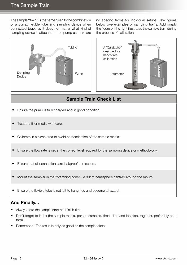
The sample ''train'' is the name given to the combination of a pump, flexible tube and sampling device when connected together. It does not matter what kind of sampling device is attached to the pump as there are
no specific terms for individual setups. The figures below give examples of sampling trains. Additionally the figure on the right illustrates the sample train during the process of calibration.
0
5
0
5
0
5
3
3
2
2
1
1
0
0
A 'Calidaptor' designed for hands free calibration
Rotameter
Tubing
PumpSampling Device
Sample Train Check List
• Ensure the pump is fully charged and in good condition.
• Treat the filter media with care.
• Calibrate in a clean area to avoid contamination of the sample media.
• Ensure the flow rate is set at the correct level required for the sampling device or methodology.
• Ensure that all connections are leakproof and secure.
• Mount the sampler in the “breathing zone” - a 30cm hemisphere centred around the mouth.
• Ensure the flexible tube is not left to hang free and become a hazard.
And Finally...• Always note the sample start and finish time.
• Don’t forget to index the sample media, person sampled, time, date and location, together, preferably on a form.
• Remember - The result is only as good as the sample taken.
The Sample Train

www.skcltd.com 224-G2 Issue D Page 17
Notes

SKC Limited 11 Sunrise Park, Higher Shaftesbury Road, Blandford Forum, Dorset DT11 8ST United Kingdom
T: +44 (0) 1258 480188 F: +44 (0) 1258 480184 E: [email protected] W: www.skcltd.com224-
G2
Issu
e D
Jul
y 20
15
Specialists in Air Sampling Technologies
A member of the SKC global group of companies