Seeedstudio Arduino Sidekick Basic Kit - RobotShop · Seeedstudio Arduino Sidekick Basic Kit...
18
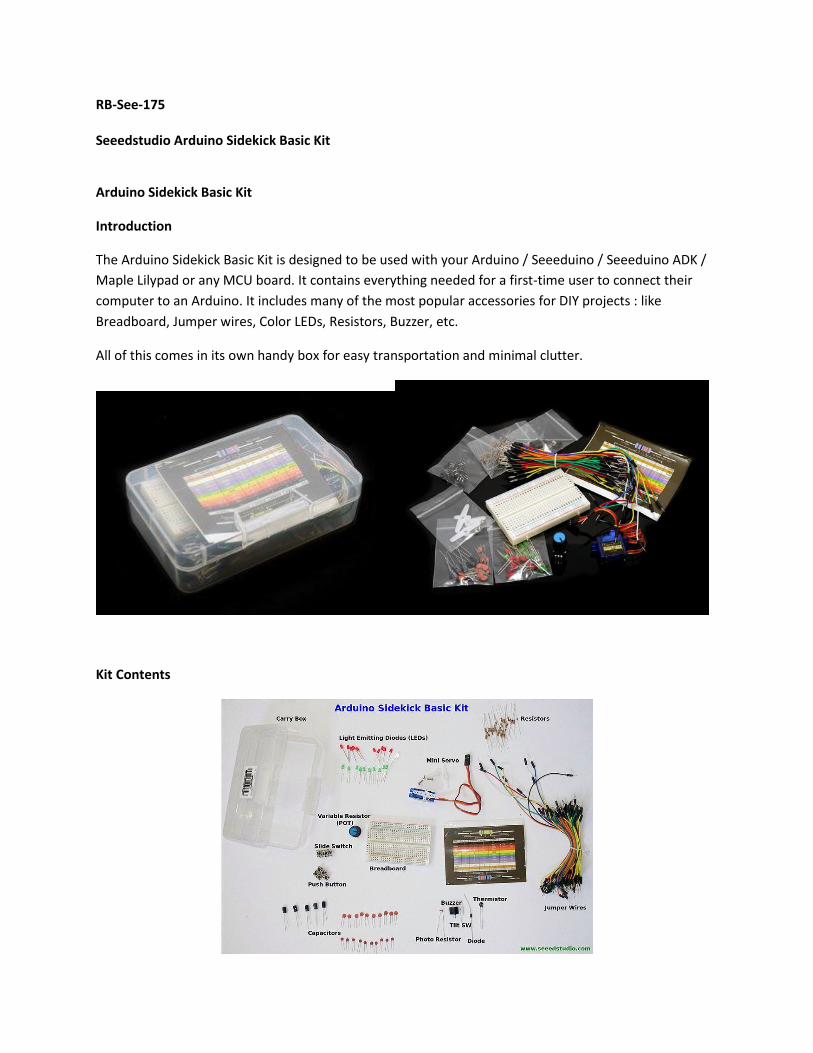
RB-See-175 Seeedstudio Arduino Sidekick Basic Kit Arduino Sidekick Basic Kit Introduction The Arduino Sidekick Basic Kit is designed to be used with your Arduino / Seeeduino / Seeeduino ADK / Maple Lilypad or any MCU board. It contains everything needed for a first-time user to connect their computer to an Arduino. It includes many of the most popular accessories for DIY projects : like Breadboard, Jumper wires, Color LEDs, Resistors, Buzzer, etc. All of this comes in its own handy box for easy transportation and minimal clutter. Kit Contents
Transcript of Seeedstudio Arduino Sidekick Basic Kit - RobotShop · Seeedstudio Arduino Sidekick Basic Kit...
RB-See-175 Seeedstudio Arduino Sidekick Basic Kit
Arduino Sidekick Basic Kit
Introduction
The Arduino Sidekick Basic Kit is designed to be used with your Arduino / Seeeduino / Seeeduino ADK /
Maple Lilypad or any MCU board. It contains everything needed for a first-time user to connect their
computer to an Arduino. It includes many of the most popular accessories for DIY projects : like
Breadboard, Jumper wires, Color LEDs, Resistors, Buzzer, etc.
All of this comes in its own handy box for easy transportation and minimal clutter.
Kit Contents
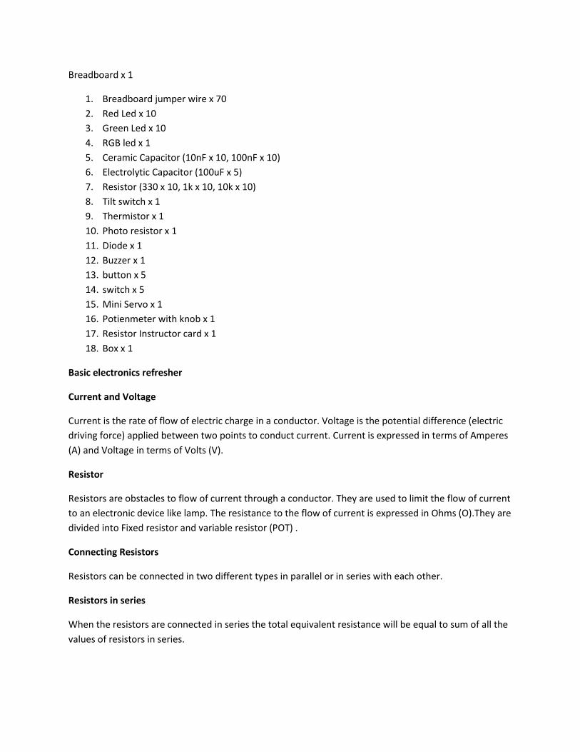
Breadboard x 1
1. Breadboard jumper wire x 70
2. Red Led x 10
3. Green Led x 10
4. RGB led x 1
5. Ceramic Capacitor (10nF x 10, 100nF x 10)
6. Electrolytic Capacitor (100uF x 5)
7. Resistor (330 x 10, 1k x 10, 10k x 10)
8. Tilt switch x 1
9. Thermistor x 1
10. Photo resistor x 1
11. Diode x 1
12. Buzzer x 1
13. button x 5
14. switch x 5
15. Mini Servo x 1
16. Potienmeter with knob x 1
17. Resistor Instructor card x 1
18. Box x 1
Basic electronics refresher
Current and Voltage
Current is the rate of flow of electric charge in a conductor. Voltage is the potential difference (electric
driving force) applied between two points to conduct current. Current is expressed in terms of Amperes
(A) and Voltage in terms of Volts (V).
Resistor
Resistors are obstacles to flow of current through a conductor. They are used to limit the flow of current
to an electronic device like lamp. The resistance to the flow of current is expressed in Ohms (O).They are
divided into Fixed resistor and variable resistor (POT) .
Connecting Resistors
Resistors can be connected in two different types in parallel or in series with each other.
Resistors in series
When the resistors are connected in series the total equivalent resistance will be equal to sum of all the
values of resistors in series.
Resistors in parallel
The total equivalent resistance of resistors in parallel is equal to the sum of their reciprocals.
Ohm's Law
The relation between Current, Voltage and Resistance is governed by Ohm's Law - Which states that
"The current through a conductor (I Amperes) between two points is directly proportional to the
potential difference or voltage across the two points(V Volts), and inversely proportional to the
resistance between them (R Ohms)"
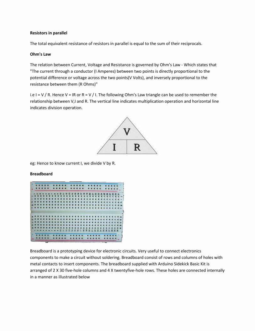
i.e I = V / R. Hence V = IR or R = V / I. The following Ohm's Law triangle can be used to remember the
relationship between V,I and R. The vertical line indicates multiplication operation and horizontal line
indicates division operation.
eg: Hence to know current I, we divide V by R.
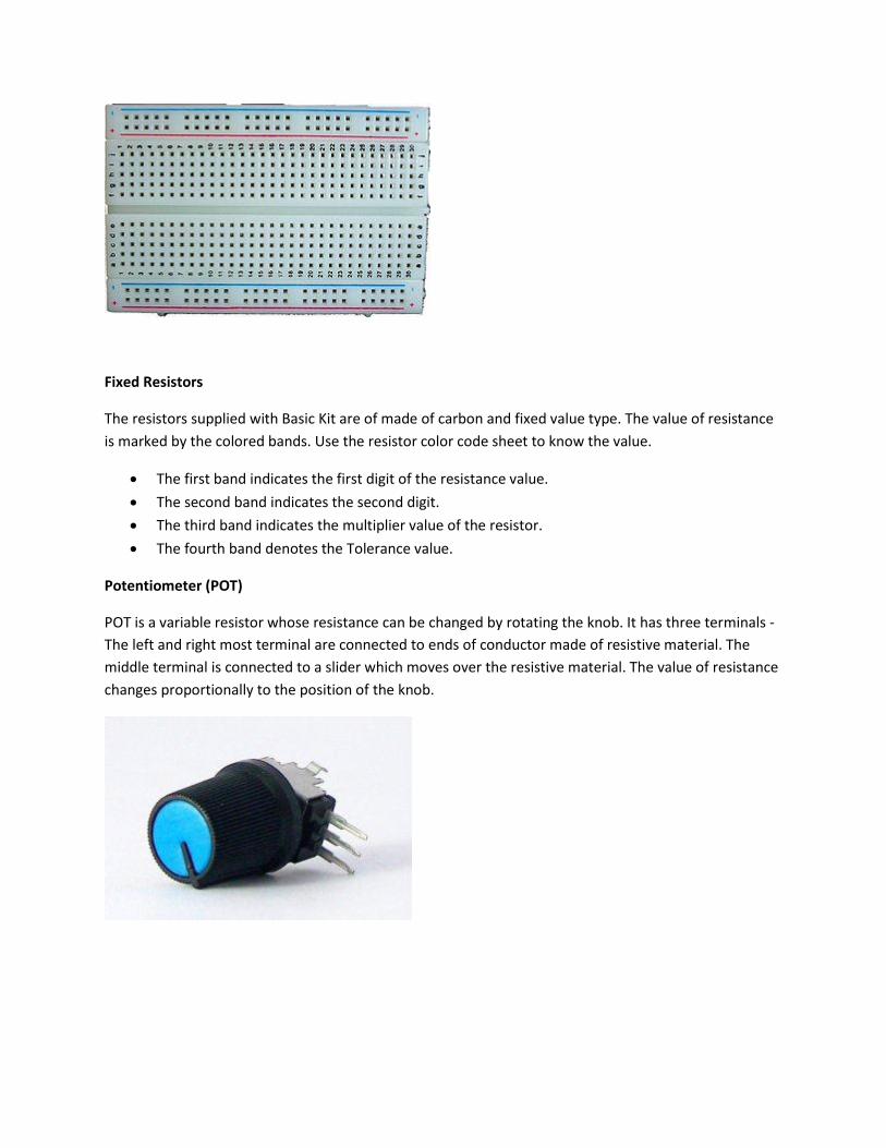
Breadboard
Breadboard is a prototyping device for electronic circuits. Very useful to connect electronics
components to make a circuit without soldering. Breadboard consist of rows and columns of holes with
metal contacts to insert components. The breadboard supplied with Arduino Sidekick Basic Kit is
arranged of 2 X 30 five-hole columns and 4 X twentyfive-hole rows. These holes are connected internally
in a manner as illustrated below
Fixed Resistors
The resistors supplied with Basic Kit are of made of carbon and fixed value type. The value of resistance
is marked by the colored bands. Use the resistor color code sheet to know the value.
The first band indicates the first digit of the resistance value.
The second band indicates the second digit.
The third band indicates the multiplier value of the resistor.
The fourth band denotes the Tolerance value.
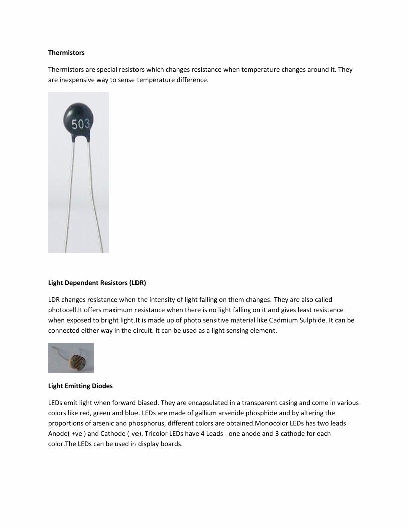
Potentiometer (POT)
POT is a variable resistor whose resistance can be changed by rotating the knob. It has three terminals -
The left and right most terminal are connected to ends of conductor made of resistive material. The
middle terminal is connected to a slider which moves over the resistive material. The value of resistance
changes proportionally to the position of the knob.
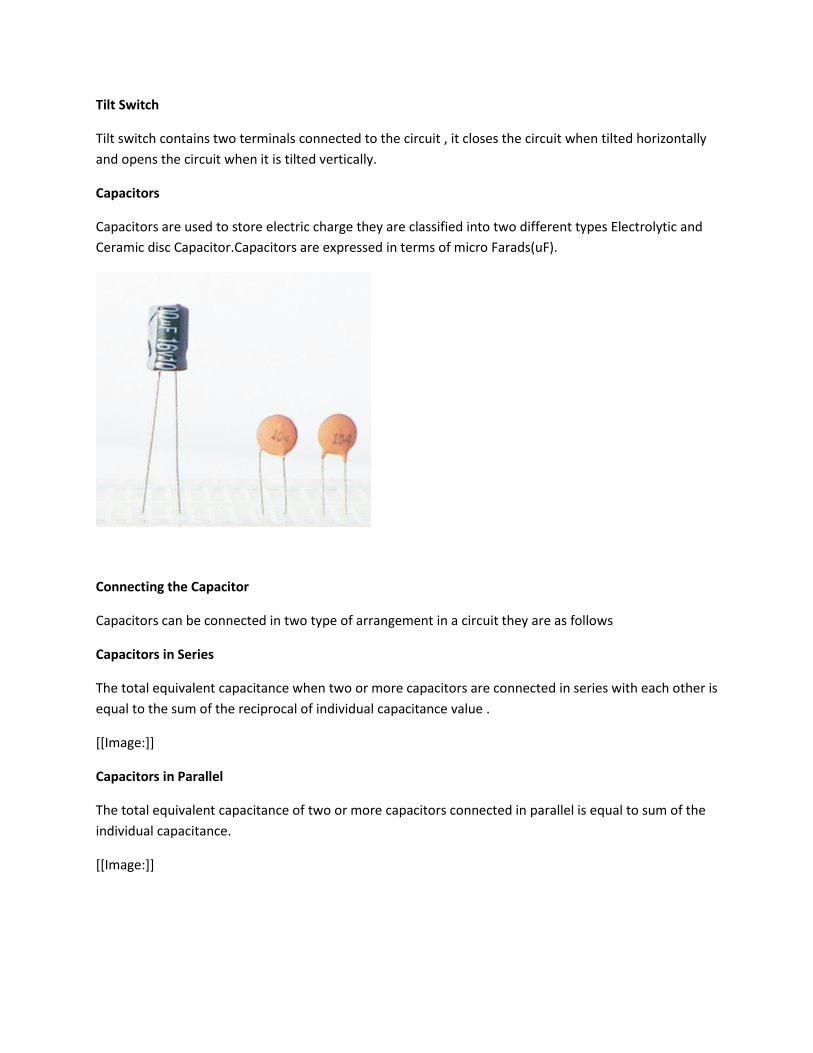
Thermistors
Thermistors are special resistors which changes resistance when temperature changes around it. They
are inexpensive way to sense temperature difference.
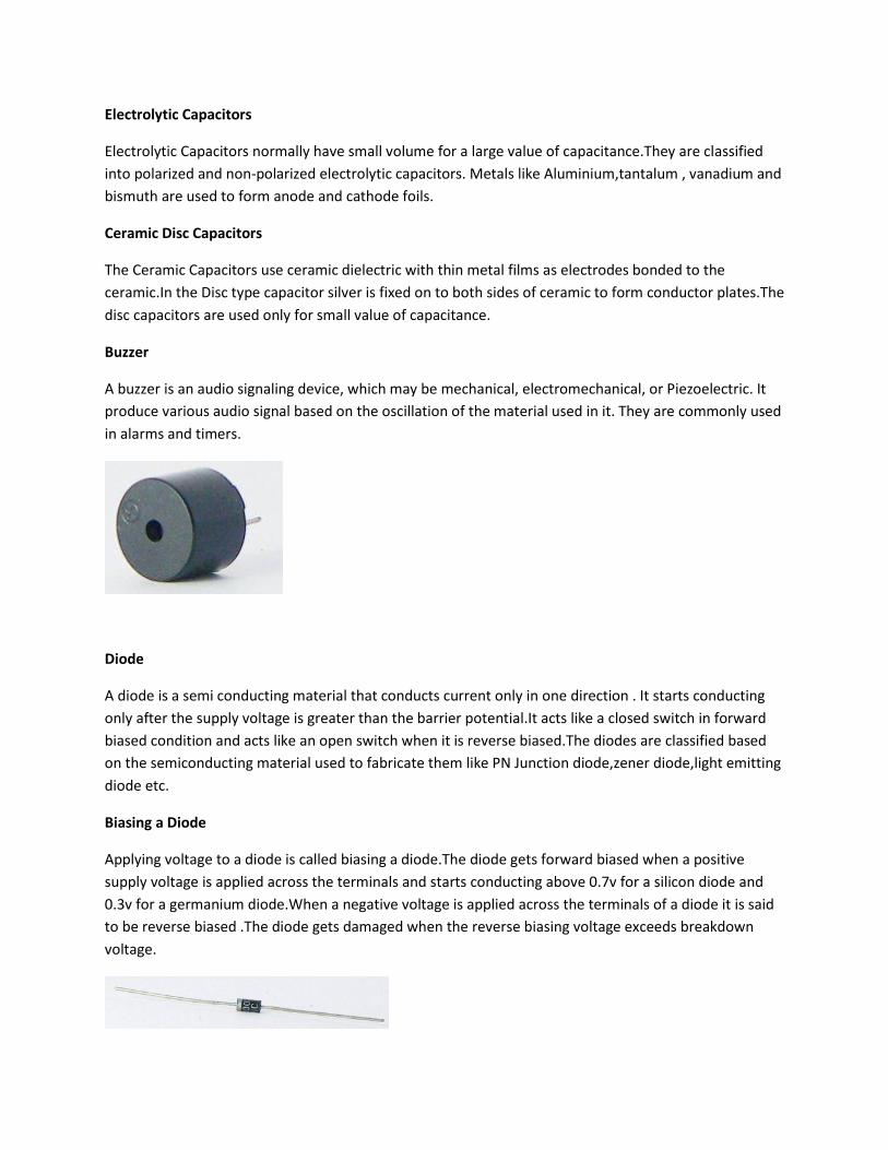
Light Dependent Resistors (LDR)
LDR changes resistance when the intensity of light falling on them changes. They are also called
photocell.It offers maximum resistance when there is no light falling on it and gives least resistance
when exposed to bright light.It is made up of photo sensitive material like Cadmium Sulphide. It can be
connected either way in the circuit. It can be used as a light sensing element.
Light Emitting Diodes
LEDs emit light when forward biased. They are encapsulated in a transparent casing and come in various
colors like red, green and blue. LEDs are made of gallium arsenide phosphide and by altering the
proportions of arsenic and phosphorus, different colors are obtained.Monocolor LEDs has two leads
Anode( +ve ) and Cathode (-ve). Tricolor LEDs have 4 Leads - one anode and 3 cathode for each
color.The LEDs can be used in display boards.

Switch
The switches are used to close or open the circuit.The switches supplied with Basic kit are of two types -
Push button switch and Slide Switch.
Push Button Switch
Push button switch close the circuit as long as it is pressed.
Slide Switch
Slide switch is a simple two position switch. It can be used to open or close a circuit by setting it to
appropriate position.
Tilt Switch
Tilt switch contains two terminals connected to the circuit , it closes the circuit when tilted horizontally
and opens the circuit when it is tilted vertically.
Capacitors
Capacitors are used to store electric charge they are classified into two different types Electrolytic and
Ceramic disc Capacitor.Capacitors are expressed in terms of micro Farads(uF).
Connecting the Capacitor
Capacitors can be connected in two type of arrangement in a circuit they are as follows
Capacitors in Series
The total equivalent capacitance when two or more capacitors are connected in series with each other is
equal to the sum of the reciprocal of individual capacitance value .
[[Image:]]
Capacitors in Parallel
The total equivalent capacitance of two or more capacitors connected in parallel is equal to sum of the
individual capacitance.
[[Image:]]
Electrolytic Capacitors
Electrolytic Capacitors normally have small volume for a large value of capacitance.They are classified
into polarized and non-polarized electrolytic capacitors. Metals like Aluminium,tantalum , vanadium and
bismuth are used to form anode and cathode foils.
Ceramic Disc Capacitors
The Ceramic Capacitors use ceramic dielectric with thin metal films as electrodes bonded to the
ceramic.In the Disc type capacitor silver is fixed on to both sides of ceramic to form conductor plates.The
disc capacitors are used only for small value of capacitance.
Buzzer
A buzzer is an audio signaling device, which may be mechanical, electromechanical, or Piezoelectric. It
produce various audio signal based on the oscillation of the material used in it. They are commonly used
in alarms and timers.
Diode
A diode is a semi conducting material that conducts current only in one direction . It starts conducting
only after the supply voltage is greater than the barrier potential.It acts like a closed switch in forward
biased condition and acts like an open switch when it is reverse biased.The diodes are classified based
on the semiconducting material used to fabricate them like PN Junction diode,zener diode,light emitting
diode etc.
Biasing a Diode
Applying voltage to a diode is called biasing a diode.The diode gets forward biased when a positive
supply voltage is applied across the terminals and starts conducting above 0.7v for a silicon diode and
0.3v for a germanium diode.When a negative voltage is applied across the terminals of a diode it is said
to be reverse biased .The diode gets damaged when the reverse biasing voltage exceeds breakdown
voltage.
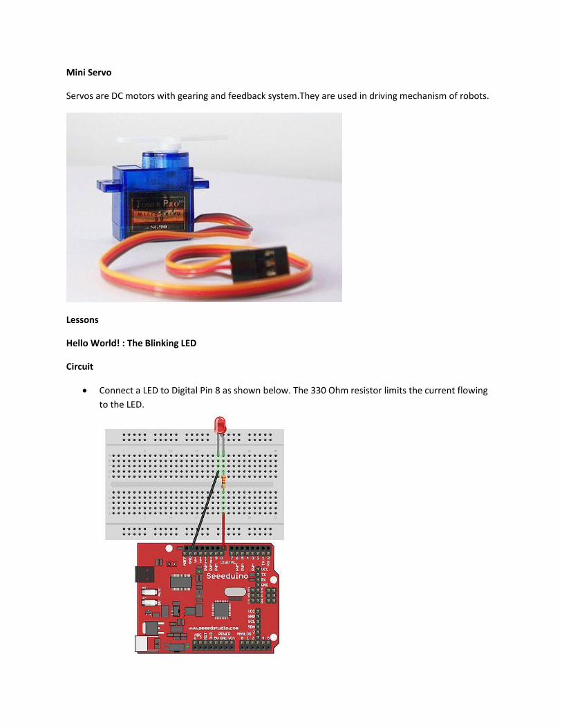
Mini Servo
Servos are DC motors with gearing and feedback system.They are used in driving mechanism of robots.
Lessons
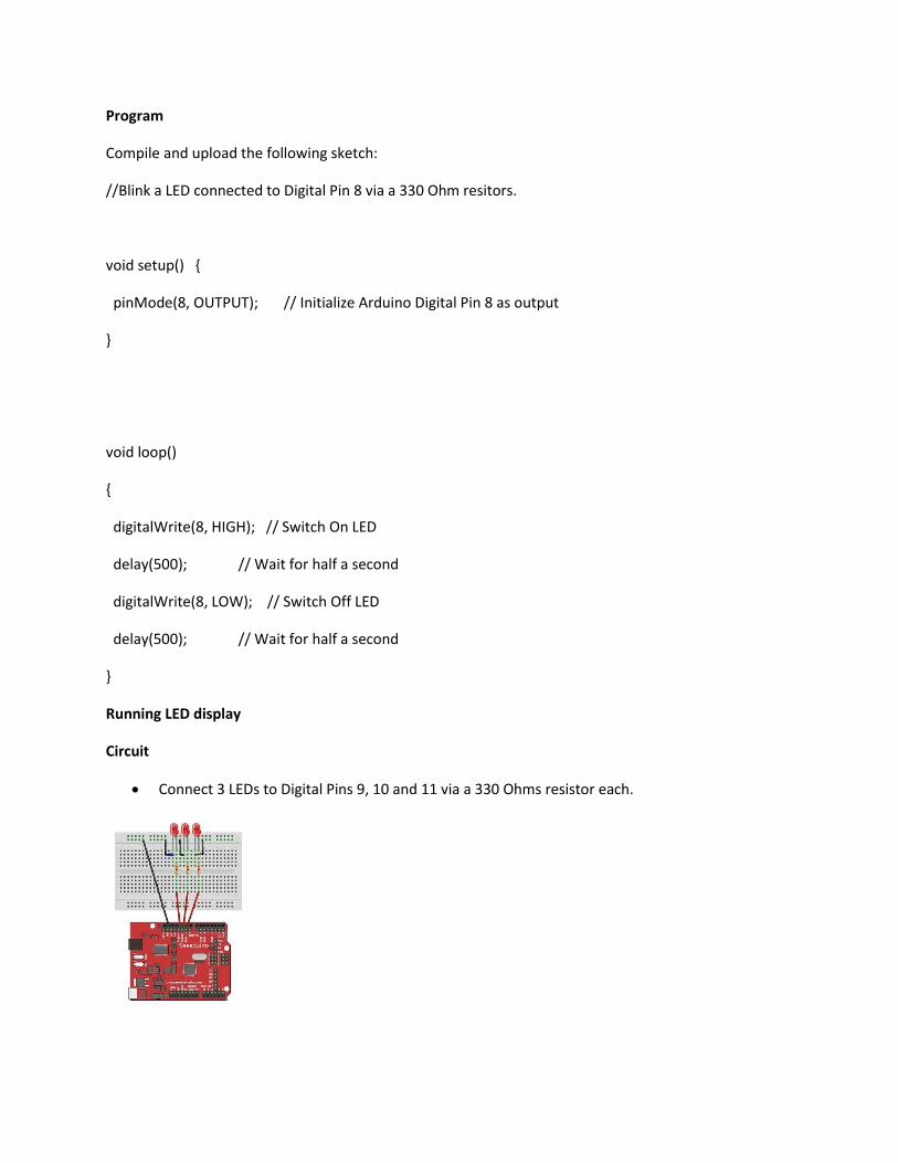
Hello World! : The Blinking LED
Circuit
Connect a LED to Digital Pin 8 as shown below. The 330 Ohm resistor limits the current flowing
to the LED.
Program
Compile and upload the following sketch:
//Blink a LED connected to Digital Pin 8 via a 330 Ohm resitors.
void setup() {
pinMode(8, OUTPUT); // Initialize Arduino Digital Pin 8 as output
}
void loop()
{
digitalWrite(8, HIGH); // Switch On LED
delay(500); // Wait for half a second
digitalWrite(8, LOW); // Switch Off LED
delay(500); // Wait for half a second
}
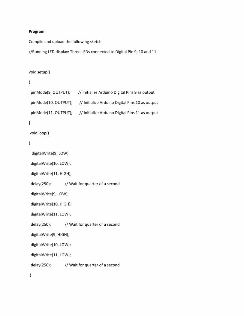
Running LED display
Circuit
Connect 3 LEDs to Digital Pins 9, 10 and 11 via a 330 Ohms resistor each.
Program
Compile and upload the following sketch:
//Running LED display: Three LEDs connected to Digital Pin 9, 10 and 11.
void setup()
{
pinMode(9, OUTPUT); // Initialize Arduino Digital Pins 9 as output
pinMode(10, OUTPUT); // Initialize Arduino Digital Pins 10 as output
pinMode(11, OUTPUT); // Initialize Arduino Digital Pins 11 as output
}
void loop()
{
digitalWrite(9, LOW);
digitalWrite(10, LOW);
digitalWrite(11, HIGH);
delay(250); // Wait for quarter of a second
digitalWrite(9, LOW);
digitalWrite(10, HIGH);
digitalWrite(11, LOW);
delay(250); // Wait for quarter of a second
digitalWrite(9, HIGH);
digitalWrite(10, LOW);
digitalWrite(11, LOW);
delay(250); // Wait for quarter of a second
}
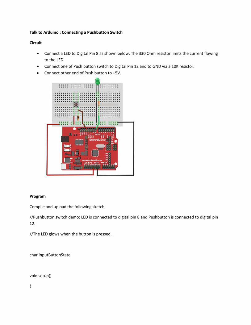
Talk to Arduino : Connecting a Pushbutton Switch
Circuit
Connect a LED to Digital Pin 8 as shown below. The 330 Ohm resistor limits the current flowing
to the LED.
Connect one of Push button switch to Digital Pin 12 and to GND via a 10K resistor.
Connect other end of Push button to +5V.
Program
Compile and upload the following sketch:
//Pushbutton switch demo: LED is connected to digital pin 8 and Pushbutton is connected to digital pin
12.
//The LED glows when the button is pressed.
char inputButtonState;
void setup()
{
pinMode(8, OUTPUT); // Initialize Arduino Digital Pins 8 as output for connecting LED
pinMode(12,INPUT); // Initialize Arduino Digital Pins 12 as input for connecting Pushbutton
}
void loop()
{
inputButtonState = digitalRead(12); //Read the Pushbutton state.
if (inputButtonState == HIGH)
{
digitalWrite(8, HIGH); //Switch on LED
}
else
{
digitalWrite(8, LOW); //Switch off LED
}
}
3 Analog : POT
Circuit
Connect anode of LED to PWM Pins via a 220 Ohms resistor .
Connect cathode of LED to GND Pin.
Mount the Pot in the bread board.
Connect the right leg of the Pot to +5v.
Connect the middle leg of the Pot to any of the Analog input pins(0-5).
Connect left leg of the Pot to the Ground Terminal.
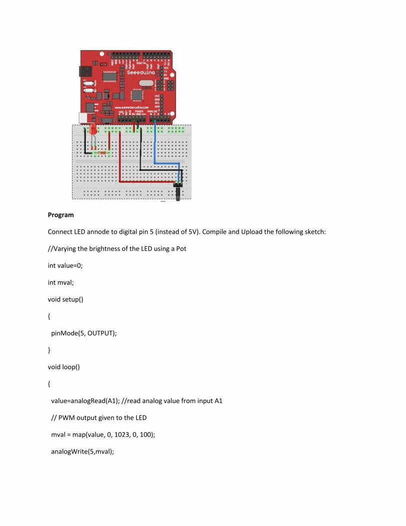
Program
Connect LED annode to digital pin 5 (instead of 5V). Compile and Upload the following sketch:
//Varying the brightness of the LED using a Pot
int value=0;
int mval;
void setup()
{
pinMode(5, OUTPUT);
}
void loop()
{
value=analogRead(A1); //read analog value from input A1
// PWM output given to the LED
mval = map(value, 0, 1023, 0, 100);
analogWrite(5,mval);

}
4 Rainbow On Desk: Tricolor LED
Circuit
RGB LED supplied with the basic kit is of common anode type. The longest lead is anode. Other three
leads are cathodes for Red, Green and Blue respectively.
Connect RGB cathodes LEDs to Digital Pins 9, 10 and 11 via a 330 Ohms resistor each.
Connect Anode to +5v
Program
Compile and upload the following sketch:
void setup() {
}
void loop() {
for(int r = 0 ; r <= 255; r=r+5)
{
for(int g = 0 ; g <= 255; g=g+5)
{
for(int b = 0 ; b <= 255; b=b+5)
{
analogWrite(9, r);
analogWrite(10, g);
analogWrite(11, b);
delay(10);
}
}
}
}
5 Music:
6 Mini Servo:
Circuit
Connect the Red colored wire of the servo motor to +5v supply.
Connect the black colored wire of the servo to ground.
Connect the yellow wire of the servo to any of the PWM pin in the Arduino.
Connect the right leg of the Pot to +5v.
Connect the middle leg of the Pot to any of the Analog input pins(0-5).
Connect the left leg of the Pot to the Ground Terminal.
Program
Compile and Upload the following sketch:
// Controlling a servo position using a potentiometer (variable resistor)
// by Michal Rinott <http://people.interaction-ivrea.it/m.rinott>
#include <Servo.h>
Servo myservo; // create servo object to control a servo
int potpin = 1; // analog pin used to connect the potentiometer
int val; // variable to read the value from the analog pin
void setup()
{
myservo.attach(5); // attaches the servo on pin 5 to the servo object
Serial.begin(19200); // some servos doesn't work without Serial
}
void loop()
{
val = analogRead(potpin); // reads the value of the potentiometer (value between 0 and 1023)
val = map(val, 0, 1023, 0, 179); // scale it to use it with the servo (value between 0 and 180)
myservo.write(val); // sets the servo position according to the scaled value
delay(15); // waits for the servo to get there
}
Usage
There is a solderless breadboard so there is no need to purchase a soldering iron or to learn how
to solder.
There are plenty of jumper wires which are long and flexible with rigid tips.These jumper wires
are much better than the old fixed length solid wire jumpers of the past.
There are plenty of LEDs and resistors for your first project including a RGB LED this is a single
LED package with with the three primary colored LEDs inside. By adjusting the intensity of the
different primary colored LEDs the colors will mix together and produce all the colors of the
rainbow.
There is even a educational how-to card or reading the resistor values.
The included tilt switch is a very simple device with a small metal ball inside. If the device is
tilted to one side the metal ball will touch electrical contacts. This sensor is useful for a variety of
projects like a DIY burglar alarm.
The thermistor is useful for projects where you want to detect the temperature.
The photo resistor can detect light, it works with light bulbs and sunlight. Photo resistors are
commonly used for detecting when it's dark and turning lights on at night.
The buzzer in the kit works especially well for playing the Mario Brothers theme song.
There is a Mini Servo motor. You can use it to open and close a deadbolt, lightswitch or valve.
You could even use it to make a mini catapult.
The potentiometer is a great input device. You can use it to control the angle of the Servo arm
or the intensity of LEDs.