
Steered Allocation
19
Wireless Pers Commun DOI 10.1007/s11277-011-0441-1 Optimized Power Allocation for Layered-Steered Space-Time Codes Ahmad S. Salim · Salam A. Zummo · Samir N. Al-Ghadhban · Ping-Cheng Yeh © Springer Science+Business Media, LLC. 2011 Abstract Layered Steered Space-Time Codes (LSSTC) is a recently proposed multiple- input multiple-output system that combines the benefits of vertical Bell Labs space-time (VBLAST) scheme, space-time block codes and beamforming. We suggest a new downlink scheme employing LSSTC with asymmetric power allocation, by assuming that the user feeds the BS with the average signal-to-noise ratio per VBLAST layer through the uplink feedback channel. The motivation behind proposing such a system is to enhance the error performance by assigning power to the layers in an optimal manner. We refer to the system proposed as the optimal power allocation LSSTC (OPA-LSSTC). Our analysis is general such that it includes asymmetric layered systems in which each layer may have different number of antennas and also the power can be assigned to layers asymmetrically. Keywords Layered-steered space-time codes · LSSTC · Performance analysis · Optimal power allocation A. S. Salim (B ) · S. A. Zummo · S. N. Al-Ghadhban Electrical Engineering Department, King Fahd University of Petroleum and Minerals (KFUPM), P. O. Box 7626, Dhahran 31261, Saudi Arabia e-mail: [email protected] S. A. Zummo e-mail: [email protected] S. N. Al-Ghadhban e-mail: [email protected] P.-C. Yeh Department of Electrical Engineering and Graduate Institute of Communication Engineering, National Taiwan University, Taipei, Taiwan e-mail: [email protected] 123
Transcript of Steered Allocation

Wireless Pers CommunDOI 10.1007/s11277-011-0441-1
Optimized Power Allocation for Layered-SteeredSpace-Time Codes
Ahmad S. Salim · Salam A. Zummo ·Samir N. Al-Ghadhban · Ping-Cheng Yeh
© Springer Science+Business Media, LLC. 2011
Abstract Layered Steered Space-Time Codes (LSSTC) is a recently proposed multiple-input multiple-output system that combines the benefits of vertical Bell Labs space-time(VBLAST) scheme, space-time block codes and beamforming. We suggest a new downlinkscheme employing LSSTC with asymmetric power allocation, by assuming that the userfeeds the BS with the average signal-to-noise ratio per VBLAST layer through the uplinkfeedback channel. The motivation behind proposing such a system is to enhance the errorperformance by assigning power to the layers in an optimal manner. We refer to the systemproposed as the optimal power allocation LSSTC (OPA-LSSTC). Our analysis is generalsuch that it includes asymmetric layered systems in which each layer may have differentnumber of antennas and also the power can be assigned to layers asymmetrically.
Keywords Layered-steered space-time codes · LSSTC · Performance analysis ·Optimal power allocation
A. S. Salim (B) · S. A. Zummo · S. N. Al-GhadhbanElectrical Engineering Department, King Fahd University of Petroleum and Minerals (KFUPM),P. O. Box 7626, Dhahran 31261, Saudi Arabiae-mail: [email protected]
S. A. Zummoe-mail: [email protected]
S. N. Al-Ghadhbane-mail: [email protected]
P.-C. YehDepartment of Electrical Engineering and Graduate Institute of Communication Engineering,National Taiwan University, Taipei, Taiwane-mail: [email protected]
123

A. S. Salim et al.
1 Introduction
Various techniques have been proposed to counter the problem of propagation conditions,and to achieve data rates that are very close to the Shannon limit. One of these techniques isusing multiple-input multiple-output (MIMO) systems which employ antenna arrays at boththe transmitter and the receiver. Wolniansky et al. has proposed in [1] the well-known MIMOscheme, known as vertical Bell Labs space-time (VBLAST). In VBLAST architecture, par-allel data streams are sent via the transmit antennas at the same carrier frequency. Given thatthe number of receive antennas is greater than or equal to the number of transmit antennas,the receiver employs a low complexity method based on successive interference cancella-tion (SIC) to detect the transmitted data streams. In this manner, VBLAST can achieve highspectral efficiencies without any need for increasing the system’s bandwidth or transmittedpower.
Alamouti has presented in [2] a new scheme called STBC with two transmit and onereceive antennas that provides the same diversity order as maximal-ratio receiver combin-ing (MRRC) with one transmit and two receive antennas. This scheme can be generalizedto two transmit antennas and M receive antennas to provide a diversity order of 2M . Sim-ilar work was considered in [3] where space time trellis codes (STTC) were used as thecomponent codes. With the tempting advantages of VBLAST and STBC, many researchershave attempted to combine these two schemes to result in a multilayered architecture calledMLSTBC [4] with each layer being composed of antennas that corresponds to a specificSTBC. This combined scheme arises as a solution to jointly achieve spatial multiplexing anddiversity gains simultaneously. With MLSTBC scheme, it is possible to increase the data ratewhile keeping a satisfactory link quality in terms of symbol error rate (SER) [5].
In [6], beamforming was combined with MLSTBC to produce a hybrid system called thelayered steered space time codes (LSSTC). The addition of beamforming to MLSTBC fur-ther improves the performance of the system by focusing the energy towards one direction,where the antenna gain is increased in the direction of the desired user, while reducing thegain towards the interfering users.
The main contribution of this paper is deriving the optimal power allocation at the trans-mitter side for an LSSTC system in order to minimize the probability of error. In this paper,we optimally design a power allocation algorithm to antenna arrays comprising an LSSTCscheme. The power allocation algorithm utilizes the channel state information feedback fromthe mobile station on the uplink to the BS, and finds the best power allocation to the channelconditions encountered by the BS. The resulting system is an LSSTC scheme with optimalpower allocation that enhances the SER performance without any further cost, except thefeedback of the channel state information and simple calculations at the BS to find the bestpower allocation scheme. We claim that optimal power allocation is first designed for LSSTCin this paper. Some of the advantages of this design is that can be added to the existing andevolving wireless communication systems, that employ MIMO such as the long-term evolu-tion (LTE) or WiMAX, seamlessly and with quite low cost as it only requires the running ofthe OPA processing algorithm without any additional hardware.
The paper is organized as follows. Section 2 presents a brief literature review on thepower allocation in layered systems. Section 3 gives a description of the system model forthe proposed scheme. Section 4 presents the notation used for the power allocation scheme.Section 5 shows the performance analysis of PA-LSSTC, in which we derive a formula forthe probability of error of the individual layers employing different modulation schemes andthe average SER of the LSSTC system. Furthermore, the optimal PA scheme for LSSTCis derived so that the probability of error is minimized. Section 6 presents the simulation
123

Optimized Power Allocation
results conducted to evaluate the PA-LSSTC system. Section 7 discusses the complexity ofthe proposed system. Finally, Section 8 presents our conclusions.
2 Related Work
In this section we briefly present some of the research literature pertaining to power alloca-tion in layered systems. Many techniques have been proposed to improve the performance oflayered systems such as VBLAST, one of which is to decrease error propagation from earlierlayers by assigning more power to those layers. An analytical derivation for the optimumpower allocation was presented in [7] for unordered VBLAST. The procedure proposed in[7] uses approximations for the total bit errorr rate (TBER) and block error rate (BLER) toderive closed forms of the optimized error rates at high SNR. According to [7], both BLER-based and and TBER-based optimization result in the same performance. A transmit powerallocation scheme for VBLAST systems is proposed in [8], this scheme uses the Lagrangemultiplier method to minimize the overall bit error rate (BER). In [9], a different approachis followed, where the authors find recursive expressions for the error rate of the individuallayers and then use Newton’s method to find the optimum power allocation for an unorderedVBLAST system. In [10–12], the performance of optimized and non-optimized VBLASTsystems was compared through numerical simulations. It was noted that applying optimumpower allocation results in a few dBs gain in the BER curve. In [13], an algorithm is derivedto find the optimum power allocation for a VBLAST system equipped with 2 transmit anten-nas. The proposed scheme in [13] numerically minimizes the probability of vector error andyields an SNR gain up to 3 dB for a 2 ×2 system at a probability of vector error of 10−3. Thedrawback of the derivation in [13] is that it is limited to the case of two transmit antennas.
Our work explores the extent to which optimal power allocation is able to minimize theprobability of error in LSSTC systems. Our analysis is a generalization of that for VBLASTin [9] to the LSSTC case, where beamforming and STBC are involved. We also investi-gate the performance of the power allocation scheme for LSSTC (PA-LSSTC) employingmulti-level quadrature amplitude modulation (Mq −QAM). Unlike the analysis presented in[9], our analysis is more general such that it includes asymmetric layered systems in whicheach layer may have different number of antenna elements. Our study also investigates theeffect of varying different LSSTC parameters on the power allocation gain. To the best ofour knowledge, no analysis on power allocation has been derived for LSSTC systems before.It would be interesting and novel to investigate the effect of asymmetric power allocation inLSSTC systems.
3 System Model
Figure 1 shows the block diagram of a PA-LSSTC system, the system has NT total transmit-ting antennas and NR receiving antennas and is denoted by an (NT , NR) system. The antennaarchitecture employed in Fig. 1 has M transmit adaptive antenna arrays (AAs) spaced suf-ficiently far apart in order to experience independent fading and hence achieve transmitdiversity. Each of the AAs consists of L elements that are spaced at a distance of λ/2 toensure achieving beamforming.
A block of B input information bits is sent to the vector encoder of LSSTC and serial-to-parallel converted to produce K streams (layers) of length B1, B2, . . . , BK , where B1 + B2
+ · · · + BK = B. Each group of Bk bits, k ∈ [1, K ], is then encoded by a component
123

A. S. Salim et al.
LSSTC processing: estimate a and decode
STC
1
1B
Rich scattering
environment
1mAA
b1L
Beamformer
b11
DOA
1AA
ST
C KKB
1Rx
RNRx
B
B
Vector Encoder:
Serial to Parallel
Converter
Tx data
of length B
Rx data
bML
Beamformer
bM1
DOA
MAA
( 1)KM mAA
PA PROCESSING
CSI
Fig. 1 Block diagram of a single user LSSTC system with power allocation
space-time code ST Ck associated with mk transmit AAs, where m1 + m2 + · · ·+ mK = M .The output of the kth ST C encoder is a mK × l codeword, ci , that is sent over l time inter-vals. The space-time coded symbols from all layers can be written as C = [c1, c2, . . . , cK ]T ,where C is an M × l matrix.
The coded symbols from C are then processed by the corresponding beamformers, andthen transmitted simultaneously over the wireless channels. The transmit antennas of allgroups are synchronized and allocated equal power, moreover, the total transmission poweris fixed, where the transmitted symbols have an average power of PT = 1, where the averageis taken across all codewords over both spatial and temporal components. For proper opera-tion, NR should be at least equal to K . The BS of PA-LSSTC prompts the user to feedbackthe CSI per layer via the feedback channel along with the direction of arrival (DOA) data.Also the transmitter is capable of performing PA processing.
The signal model can be described in matrix notation, where the received baseband datamatrix can be written as
Y = HWC + N, (1)
where Y is the received signal over l time intervals and has a dimension of NR × l, H is amatrix of vectors of dimension NR × M whose entries are hn,m , where hn,m is the L-dimen-sional channel impulse response (CIR) vector spanning the mth AA, m ∈ [1, . . . , M] andthe nth receiver antenna, n ∈ [1, . . . , NR] as hn,m(t). The NR × l noise matrix, N, charac-terizes the additive white Gaussian noise (AWGN). The nth row of N denoted as zn , wheren ∈ [1, . . . , NR], is a row vector of l columns, the i th entry of zn is a spatially uncorrelatedcircular-complex normal random variable, and can be written as zi
n = ziI,n + j zi
Q,n , where
ziI,n and zi
Q,n are two independent zero-mean Gaussian random variables having a variance
of N0/2. We will represent zin as CN (0, N0). Furthermore, W is a diagonal weight matrix of
vectors of dimension M × M whose diagonal entry wm,m is the L-dimensional beamforming
123

Optimized Power Allocation
weight vector for the mth beamformer AA and the nth receive antenna, and can be writtenas wm,m = [bm1, . . . , bmL ], where bmi , i ∈ [1, . . . , L], is the i th weighting gain of the mthAA.
Throughout this paper, the phrase “sub-stream” is used to refer to the data stream of eachAA, whereas, the term “layer” represents the data stream to be encoded by STBC. The trans-mitted symbols can be written in vector form as x = [x1, . . . , xM ]T , where xi is the i thsub-stream sent by the i th AA.
After multiplying the channel matrix (H) by the weighting matrix (W) and performingsome matrix manipulations, the received signal can be written as
Y = LHC + N, (2)
where H is an (NR × M) matrix whose entries are αn,m , which is the Rayleigh faded channelcoefficient coupling the mth AA to the nth receiver antenna. Further, H can be Partitionedinto groups corresponding to each layer as in [4]
H =[h1, . . . , hK
], (3)
where hk is the channel matrix of the kth layer. Looking at (2), the effect of beamforming canbe clearly seen as a direct gain in the signal-to-noise ratio (SNR). Expressing HC in termsof the layer components we get
Y = LK∑
k=1
hkck + N, (4)
where ck represents the component STBC used at layer k, where k ∈ [1, . . . , K ].
4 The Power Allocation Scheme
The power allocation pattern for the PA-LSSTC system is characterized by the vector K =[K1, K2, . . . , KM−1], where Ki is defined as the transmit power ratio of the i th sub-streamto the sum of power of sub-streams i + 1, . . . , M . Hence, the parameter Ki is defined by
Ki = Pi∑Mj=i+1 Pj
, i = 1, 2, . . . , M − 1, (5)
where Pi denotes the transmit power of the i th sub-stream. Similarly, we define the layer PApattern as KL = [KL ,1, KL ,2, . . . , KL ,K−1] where K is the number of layers, and KL ,i isdefined as the transmit power ratio of the i th layer to the sum of power of layers i +1, . . . , K .KL ,i is defined by
KL ,i = PL ,i∑Kj=i+1 PL , j
, i = 1, 2, . . . , K − 1, (6)
where PL ,i denotes the transmit power of the i th layer. For fair comparison among differentPA patterns, the PA pattern must satisfy the total power constraint defined as PT = ∑M
i=1 Pi ,where PT is assumed to to be equal to the average transmit power per modulation symbol.
123

A. S. Salim et al.
5 Performance Analysis
In this section, the performance of LSSTC systems employing PA scheme is analyzed. Thereceiver is assumed to have a fixed detection ordering and uses serial group interferencecancellation (SGIC) for detection [4]. The analysis is carried out for slow Rayleigh fadingchannels, in which we assume that the channel remains constant for many STBC blocks.Thus, the transmitter obtains the estimates of the average SNR per layer from the receiver,finds the optimal power allocation pattern, and uses the same power allocation pattern tillthe channel changes. Using this assumption minimizes the feedback load by a significantamount.
The sub-stream error will depend on the number of errors that occurred in the sub-streamitself and on the errors propagating from the previous layers, and will not depend on theerrors occurring in the other sub-streams of the same layer. Therefore, we will calculatethe layer probability of error, which will be equal to the probability of sub-stream error ofthe sub-streams sent from that layer. Therefore throughout this paper we will express thelayer performance in terms of that of one of its substreams. For the i th layer the latter willbe denoted as si . Similar to the analysis in [9], we first denote the SER of the i th layer underPA pattern KL and noise of variance N0 as Pei |(KL ,N0) = P{si �= si
∣∣ KL , N0}, where si
represents the estimate of si . The SER of the i th layer has the form
Pei |(KL ,N0) =i−1∑l=0
P{si �= si , Ali−1
∣∣ KL , N0}, (7)
where Ali−1 defines the event of having l errors in the symbols s1 ∼ si−1. Let Vm denote one
of the(
i−1l
)events which has detection errors at certain l layers among the i − 1 processed
layers at each time slot. Thus Vm is a set that contains the layer indices for one of the(
i−1l
)
combinations of choosing l error symbols among the i−1 layers, where m = 1, 2, . . . ,(
i−1l
).
We can express Vm as a set Vm = {vm,1, vm,2, . . . , vm,l} where vm,k denotes the index of thelayer in which the kth error has occurred. For instance, if Vm = {1, 3, 4} then the first errorwas in the first layer, while the second was in the third layer, and the third was in the fourthlayer. Also, we assume that vm,1 < vm,2 < · · · < vm,l , vm,k ∈ {1, 2, . . . , i − 1}. Furthermore, the complement set of Vm is defined as
Wm = {1, 2, . . . , i − 1} − Vm = {wm,1, wm,2, . . . , wm,i−1−l},where wm,1 < wm,2 < · · · < wm,i−1−l , wm,k ∈ {1, 2, . . . , i − 1}. We define ei
Vmas the
event of having the i th layer in error and having l erroneous layers indicated by Vm given aspecific PA pattern KL and a noise of variance N0 as follows
eiVm
={
si �= si
⋂∀vm,k∈Vm
{svm,k �= svm,k }⋂
∀wm,k∈Wm
{swm,k = swm,k }∣∣ KL , N0
}. (8)
Then, then the probability that the i th layer along with l proceeding layers defined by Vm givenKL and N0 can be found by simply summing the probability of all the possible combinationsof Vm . Mathematically, we can write this as
123

Optimized Power Allocation
P{si �= si , Ali−1
∣∣ KL , N0} =
(i−1
l
)∑m=1
P(eiVm
). (9)
Moreover, P(eiVm
) can be decomposed into a product of i components as follows
P(eiVm
) = P(ei,iVm
) · P(ei,i−1Vm
) · · · P(ei,1Vm
) =i∏
t=1
P(ei,tVm
), (10)
where ei,tVm
is defined similar to eiVm
except that it corresponds to the t th layer (whether
erroneous or correct). ei,tVm
is defined as
ei,tVm
=
⎧⎪⎪⎪⎪⎪⎪⎪⎪⎪⎪⎨⎪⎪⎪⎪⎪⎪⎪⎪⎪⎪⎩
{st �= st
∣∣ ⋂∀vm,k<t
{svm,k �= svm,k }⋂
∀wm,k<t{swm,k = swm,k }, KL , N0
}, t ∈ Vm .
{st = st
∣∣ ⋂∀vm,k<t
{svm,k �= svm,k }⋂
∀wm,k<t{swm,k = swm,k }, KL , N0
}, t ∈ Wm .
(11)
Thus, substituting (10) in (9) results in
P{si �= si , Ali−1
∣∣ KL , N0} =
(i−1
l
)∑m=1
i∏t=1
P(ei,tVm
). (12)
The exact SER of the t th layer without error propagation given the diversity order andthe SNR have been derived in [14] for different modulation schemes. We denote the SERof the t th layer as Pe(Dt , ρt ), where Dt is the diversity order of the t th layer, defined asDt = mt (NR − K + t), and ρt is the SNR of the t th layer, which can be written in termsof the layer power and the effective noise variance as ρt = Pt/σ
2t . The effective noise vari-
ance, σ 2t , is composed of two parts; the noise from the the currently detected symbol and the
potential error propagation signal from the earlier detected symbols. Noting the expressionfor the diversity order of LSSTC above, the effect of using STBC with VBLAST can beclearly seen, where the diversity order of each layer compared to VBLAST is increased by afactor equal to the STBC size of that specific layer. To find the probability of the event ei,t
Vmdefined in (11), we express it in terms of Pe(Dt , ρt ) for both correct and erroneous layers asfollows
P(ei,tVm
) ={
Pe(mt (NR − K + t), Pt/σ2t ), t ∈ Vm
1 − Pe(mt (NR − K + t), Pt/σ2t ), t ∈ Wm,
(13)
where the value of σ 2t depends on the modulation scheme and the symbol energy used in
previous layers.In this paper we consider QAM modulation. The reader may refer to our results in [15]
for other modulation schemes such as phase shift keying (PSK). Under a Rayleigh fadedchannel with diversity order Di , the SER of a square Mq − QAM [16] can be written as
123

A. S. Salim et al.
Pe(Di , ρi ) = 4
(1 − 1√
Mq
)I1 − 4
(1 − 1√
Mq
)2
I2, (14)
where the terms I1 and I2 are defined as
I1 =[
1
2(1 − μi )
]Di
·Di −1∑k=0
(Di − 1 + k
k
) [1
2(1 + μi )
]k
, (15)
I2 = 1
4− μi ·
(1
2− 1
π· tan−1(μi )
)·
Di −1∑k=0
(2k
k
)· (4τi )
−k
+μi
πsin
(tan−1(μi )
) Di −1∑k=1
k∑i=1
τ−ki · Tik · (
cos(tan−1(μi )
))2(k−i)+1, (16)
where
μi �√
ρi23 (Mq − 1) + ρi
, (17)
τi �(
3ρi
2(Mq − 1)+ 1
), (18)
Tik �(2k
k
)(2(k−i)
k−i
)4i · (2(k − i) + 1)
. (19)
The variance of the effective noise affecting the t th layer is approximated by
σ 2t = N0 +
∑∀vm,k<t
E[‖hvm,k ‖2
]· Var
[evm,k | xvm,k �= xvm,k
]
= N0 +∑
∀vm,k<t
L2 · 6
Mq − 1PL ,vm,k
= N0 + 6L2
Mq − 1·
∑∀vm,k<t
PL ,vm,k , (20)
where hvm,k , PL ,vm,k , and evm,k denote the channel matrix, transmit power, and the errorevent of layer vm,k , respectively. The notation E[.] is the expectation operator, V ar [.] is thevariance operator, and ‖.‖2 is the squared Frobenious norm.
After finding the expressions of σ 2t and Pe(Di , ρi ), they can be substituted into (13). The
SER of the i th layer, Pei |(KL ,N0) can be evaluated by combining (7), (12), and (13), and fromthat we can find the probability of error of the i th sub-stream by
Pexi |(K,N0) = Prob{xi �= xi | K, N0)} (21)
= Pe�(i)|(KL ,N0), (22)
where �(i) is the layer from which the i th sub-stream is sent. The average probability ofsymbol error over all M sub-streams is simply written as
Pav|(K,N0) = 1
M·
M∑i=1
Pexi |(K,N0). (23)
123

Optimized Power Allocation
In the sequel, we aim to find the optimal PA pattern K that would result in optimizing theperformance by minimizing the probability of error for the LSSTC system. To achieve thiswe need to differentiate the formula of the average SER Pav|(K,N0) with respect to K to findthe minimum value of the SER. Clearly such analytical differentiation is very difficult, there-fore we use a numerical approach applying Newton’s method [9]. To minimize Pav|(K,N0),we need to find the value of K = [K1, K2, . . . , KM−1] that satisfies the following set ofequations
∂ Pav|(K,N0)
∂Ki= 0, i = 1, 2, . . . , M − 1. (24)
To solve the set of equations in (24) by Newton’s method, we start with an initial guessand the optimal PA pattern Kopt is obtained by iterating until the solution converges, whichdepends on the initial guess and the step size.
6 Numerical Results
In this section we present some simulation results of the proposed PA scheme for LSSTCsystems with different modulation schemes and transmitter configurations. Throughout thispaper, EPA-LSSTC will be used to denote equal power allocation LSSTC system in whichall the layers are assigned the same amount of power. On the other hand, OPA-LSSTC willbe used to denote optimal power allocation LSSTC system in which the layers are assigneddifferent amounts of power according to Kopt .
The detection process can be classified into two types [17]. The first type is the non-ordereddetection, in which choosing the layer to be detected does not depend on the power of thelayer, and the detection order is predetermined before the signal is received. The secondtype is the post-ordered detection, where the detection order is not known until the channelrealization is perfectly estimated at the receiver.
In the Figs. 2, 3, 4, we verify our analysis by comparing it to the simulation results. Figure 2shows the SER of the individual layers of an 8 × 2 LSSTC using non-ordered SGIC detectoremploying BPSK modulation with K = 2 and L = 2 obtained from both the simulationand the analysis. The Figure compares the analytical results of the SER to those obtainedfrom the simulation with equal power allocation. It is clear that the simulation makes a nearlyperfect match to the analysis results, which demonstrates the validity of the proposed analysismethod.
Figure 3 compares the simulation results to those obtained from the analysis for SER ofan LSSTC system employing non-ordered SGIC and BPSK modulation with K = 4 andNR = 2 and different number of beamforming elements. It can be seen that the simulationand analysis results match quite well, which proves the validity of the analysis.
Figure 4 shows a fair comparison between different transmitter configurations of theLSSTC system in terms of the SER, obtained from both the EPA-LSSTC analysis and sim-ulation. The three configurations use a total number of transmit antennas, NT = 8, and thereceiver is equipped with 4 antennas. In this comparison a different modulation scheme isused such that the spectral efficiency would be the same for all of them, which is set to 4bps/Hz.
In the Figs. 5, 6, 7, 8, 9, 10, we show some numerical results for the OPA-LSSTC. A16 × 4 OPA-LSSTC employing 16-QAM modulation with K = 4 and L = 2 is considered.The optimal PA for each layer versus Es/N0 is plotted in Fig. 5, where it can be seen that athigh SNR, the impact of error propagation is more dominant than the noise. It can be seen
123

A. S. Salim et al.
0 5 10 1510
−4
10−3
10−2
10−1
100
Es/N
0 (dB)
SE
R
Analysis (Layer 1) Analysis (Layer 2) Analysis (average) Simulation (Layer 1) Simulation (Layer 2) Simulation (average)
Fig. 2 SER of the individual sub-streams of an 8 × 2 LSSTC employing SGIC without ordering and BPSKmodulation with K = 2 and L = 2 (comparing analysis to simulation results)
0 5 10 15
10−3
10−2
10−1
Es/N
0 (dB)
SE
R
Analysis (L= 1 & NT= 4)
Analysis (L= 2 & NT= 8)
Analysis (L= 4 & NT=16)
Simulation (L= 1 & NT= 4)
Simulation (L= 2 & NT= 8)
Simulation (L= 4 & NT=16)
Fig. 3 SER of LSSTC employing non-ordered SGIC and BPSK modulation with K = 4 and NR = 4(comparing analysis to simulation results)
from Fig. 5 that the SER is dominated by the first layer, and that the detection errors in thefirst layer would cause severe detection errors to the following layers, therefore, the optimalPA scheme suggests assigning the earlier layers higher power than the later ones as the SNRincreases. Note that the first layer gets most of the transmit power at high SNR since it isthe weakest layer that has the lowest diversity order among all layers. In Fig. 6, we plot theSER of a 16 × 4 LSSTC system employing 16-QAM modulation with K = 4 and L = 2.We compare two cases, PA-LSSTC with equal power allocation (EPA-LSSTC), and the
123

Optimized Power Allocation
0 2 4 6 8 10 12 14 1610
−9
10−8
10−7
10−6
10−5
10−4
10−3
10−2
10−1
100
Es/N
0 (dB)
SE
R
Analysis (BPSK, L= 1 & K= 4 NT= 8)
Analysis (QPSK, L= 2 & K= 2 NT= 8)
Analysis (16 QAM, L= 4 K= 1 & NT= 8)
Simulation (BPSK, L= 1 & K= 4 NT= 8)
Simulation (QPSK, L= 2 & K= 2 NT= 8)
Simulation (16 QAM, L= 4 K= 1 & NT= 8)
Fig. 4 SER of LSSTC employing non-ordered SGIC at 4 bps/Hz and different modulation schemes withNT = 8 and NR = 4 (comparing analysis to simulation results)
15 20 25 30 35 400
0.2
0.4
0.6
0.8
1.0
Es/N
0 (dB)
Laye
rs’ O
ptim
al P
ower
Ass
ignm
ent
Optimal PL,1
Optimal PL,2
Optimal PL,3
Optimal PL,4
Fig. 5 Optimal PA for each layer for a 16 × 4 OPA-LSSTC scheme employing 16-QAM modulation withK = 4 and L = 2
PA-LSSTC with optimal power allocation (OPA-LSSTC). Our SER analysis is shown to bevery accurate as compared to simulation results. It is observed that the proposed OPA-LSSTChas about 2.8 dB gain at a SER of 10−4 compared to EPA-LSSTC. This shows the superiorperformance of the proposed scheme.
Now, we want to study the effect of changing the parameters of the LSSTC system onthe PA gain, which we define as the difference between the SNR levels of the EPA-LSSTC
123

A. S. Salim et al.
0 5 10 15 20 25 30 35 4010
−5
10−4
10−3
10−2
10−1
100
Es/N
0 (dB)
SE
R
16 x 4 EPA−LSSTC Analysis 16 x 4 OPA−LSSTC Analysis 16 x 4 OPA−LSSTC Simulation
Fig. 6 SER of 16×4 LSSTC system using OPA-LSSTC scheme employing 16-QAM modulation with K = 4and L = 2
0 2 4 6 8 10 12 14 161
2
3
4
5
6
7
Pow
er A
lloca
tion
Gai
n, G
PA (
dB)
Number of Beam−Steering Elements (L)
Fig. 7 PA gain, G P A versus the number of beam-steering elements (L) at a SER of 10−6 using SGICemploying BPSK modulation with K = 4, mk = 2 and NR = 4
and the OPA-LSSTC required to reach the same SER. Figure 7 shows the PA gain, G P A
(dB) versus the number of beam-steering elements (L) at a SER of 10−6 using SGIC andBPSK modulation with K = 4, mk = 2, and NR = 4. It is observed that the gain remainsapproximately constant and does not depend on L , which is actually expected since L is not
123

Optimized Power Allocation
2 3 4 53
3.2
3.4
3.6
3.8
4
4.2
4.4
4.6
4.8
Pow
er A
lloca
tion
Gai
n, G
PA (
dB)
Number of AAs associated with each STBC encoder (mk)
Fig. 8 PA gain, G P A versus the number of AAs associated with each STBC encoder (mk ) at a SER of 10−6
using SGIC employing BPSK modulation with K = 4, L = 2 and NR = 4
1 2 3 4 5 6 7 80
0.5
1
1.5
2
2.5
3
3.5
4
Pow
er A
lloca
tion
Gai
n, G
PA (
dB)
Number of Layers (K)
Fig. 9 PA gain, G P A versus the number of Layers (K ) at a SER of 10−6 using SGIC employing BPSKmodulation with mk = 2, L = 2 and NR = 8
related directly to the distribution of the power among the layers, i.e. if L increase or decreasethe layer will still get the same amount of power.
Figure 8 shows the PA gain, G P A (dB) versus the number of AAs associated with eachSTBC encoder (mk) at a SER of 10−6 using SGIC and BPSK modulation with K = 4,L = 2, and NR = 4. It can be seen that G P A does not increase significantly with increasingmk . The small increase can be related to the diversity order.
123

A. S. Salim et al.
0 5 10 15 20 2510
−6
10−5
10−4
10−3
10−2
10−1
100
Es/N
0 (dB)
SE
R
EPA with non−ordered detectorEPA with post−ordered detectorOPA with non−ordered detectorOPA with post−ordered detector
1.6 dB
0.5 dB 1.2 dB
Fig. 10 SER of 16 × 4 LSSTC employing SGIC and BPSK modulation with K = 4 and L = 2 (simulationresults)
Table 1 Possible transmitter-receiver configurations for LSSTC
Transmitter Receiver
Non-ordered detector Post-ordered detector
Equal power allocation EPA-LSSTC EPA-LSSTC
with non-ordered detector with post-ordered detector
Optimal power allocation OPA-LSSTC OPA-LSSTC
with non-ordered detector with post-ordered detector
In Fig. 9 we plot the power allocation gain, G P A (dB) versus number of Layers (K ) at aSER of 10−6 using SGIC employing BPSK modulation with mk = 2, L = 2, and NR = 8,where it can be seen that G P A increases with increasing K , which is expected, since increas-ing the number of layers will lead to an increase in the degrees of freedom. Therefore a betterdistribution for the power can be found, since the total number of layers over which the powercan be distributed is increased.
We can summarize four possible Transmitter-Receiver configurations for LSSTC inTable 1.
Figure 10 plots the SER versus Es/N0 of the four possible configurations listed in Table 1.Looking at the SER around 10−5, we can see that in the case of EPA using the post-ordereddetector provides a gain of 1.2 dB compared to using the non-ordered detector, while in thecase of OPA using the post-ordered detector provides a gain of 0.5 dB compared to usingthe non-ordered detector, because the OPA had already pre-ordered the detection of the sub-streams, therefore attempting to further order them by the post-ordered detector will not resultin much gain. We can also note that the using the OPA is better than using the post-ordereddetector, since it provides about 2.8 dB gain compared to 2.1 dB for the latter. In addition, the
123

Optimized Power Allocation
0 5 10 15 20 25 30 35 4010−9
10−8
10−7
10−6
10−5
10−4
10−3
10−2
10−1
100
Es/N
0 (dB)
SE
R
Layer 1 (L= 1)Average (L= 1)Layer 1 (L= 2)Average (L= 2)Layer 1 (L= 4)Average (L= 4)
Fig. 11 First layer and average SER of EPA-LSSTC employing SGIC and BPSK modulation with K = 2,NR = 2 and mk = 2 (varying the number of beamforming elements (L))
post-ordered detector will require more processing at the user handset and that will consumethe battery, on the other hand, the PA will be done at the base station where the processingand power is not an issue.
It has been mentioned earlier that the first layer dominates the probability of error, there-fore we can approximate the average probability of error of the whole system by that of thefirst layer. In the following, we seek to further study the last statement, by comparing theSER of the first layer to the average SER, aiming to find which parameters or conditions willmake this approximation much accurate.
Figure 11 shows the SER of LSSTC with varying the number of beamforming elements(L), where we can see that the gap between the first layer and the average doesn’t change,and therefore it does not depend on L .
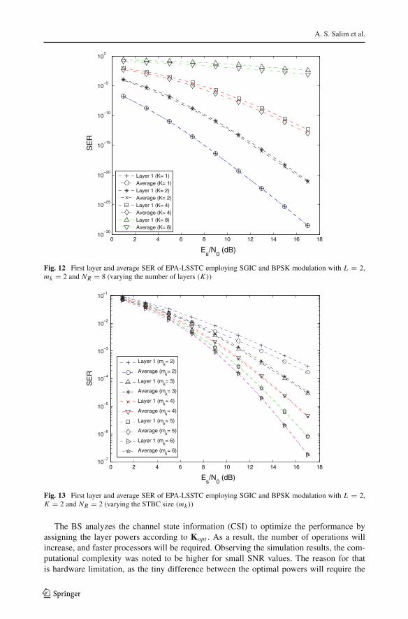
Figure 12 shows the SER of LSSTC with varying the number of layers (K ), and we cansee that the gap between the first layer and the average increases with increasing K .
In Fig. 13 the SER of LSSTC is plotted with varying the STBC size (mk) which corre-sponds to the number of AAs per layer. We can see that the gap between the first layer and theaverage decreases with increasing mk . We can also note that the gap becomes constant whenmk becomes high, this is because the diversity order becomes high and the improvementdoesn’t change much after further increase in mk .
7 Complexity of OPA-LSSTC
It was observed that the OPA at high SNR provides a significant SNR gain with a littleincrease in the complexity of the signal. The main parameters that will be affected by theOPA processing are the feedback load and the number of operations per unit time.
123
A. S. Salim et al.
0 2 4 6 8 10 12 14 16 1810
−30
10−25
10−20
10−15
10−10
10−5
100
Es/N
0 (dB)
SE
R
Layer 1 (K= 1)Average (K= 1)Layer 1 (K= 2)Average (K= 2)Layer 1 (K= 4)Average (K= 4)Layer 1 (K= 8)Average (K= 8)
Fig. 12 First layer and average SER of EPA-LSSTC employing SGIC and BPSK modulation with L = 2,mk = 2 and NR = 8 (varying the number of layers (K ))
0 2 4 6 8 10 12 14 16 1810
−7
10−6
10−5
10−4
10−3
10−2
10−1
Es/N
0 (dB)
SE
R
Layer 1 (mk= 2)
Average (mk= 2)
Layer 1 (mk= 3)
Average (mk= 3)
Layer 1 (mk= 4)
Average (mk= 4)
Layer 1 (mk= 5)
Average (mk= 5)
Layer 1 (mk= 6)
Average (mk= 6)
Fig. 13 First layer and average SER of EPA-LSSTC employing SGIC and BPSK modulation with L = 2,K = 2 and NR = 2 (varying the STBC size (mk ))
The BS analyzes the channel state information (CSI) to optimize the performance byassigning the layer powers according to Kopt . As a result, the number of operations willincrease, and faster processors will be required. Observing the simulation results, the com-putational complexity was noted to be higher for small SNR values. The reason for thatis hardware limitation, as the tiny difference between the optimal powers will require the
123

Optimized Power Allocation
step size δ to be very small. In such a case, finding the solution by numerical methods willrequire a huge number of operations. The step size used to solve the optimal PA equationsranged from 10−4 to 0.1, typically, values below 10−2 gave accepted results. Also it shouldbe clear that finding the OPA will not improve the performance much in the low SNR range,and therefore no need to allocate powerful computational resources for it. For the high SNRrange, few operations are enough to provide the optimal performance.
To speed up the convergence of finding Kopt , the BS can have a database that containsthe best initial guess of each SNR value. This way the number of operations required will beminimized and the system resources are used efficiently. The feedback load does not increasemuch when using OPA-LSSTC since we have assumed that the channel changes slowly, andthe CSI need to be sent only if the channel state changes.
8 Conclusions
In this paper we investigated the performance of single-user PA-LSSTC. We have derived anexpression for the probability of error for PA-LSSTC employing M-QAM modulation whichincludes the diversity gain of STBC and the SNR gain of beamforming. The analytical resultshave shown merely a perfect match with simulation results, which proves their validity. Alsothe benefits of PA-LSSTC in improving the performance were clearly demonstrated. Finally,the optimal PA performance for LSSTC was derived using Newton’s method. It was shownthat the OPA-LSSTC for some structure can provide about a 2.8 dB gain over the existingEPA-LSSTC of the same structure. This gain has been provided with merely no cost, theonly cost is the OPA processing at the BS which is insignificant.
Acknowledgments The authors would like to acknowledge the support provided by King Fahd Universityof Petroleum and Minerals (KFUPM) and King Abdulaziz City for Science and Technology (KACST) throughthe Science and Technology Unit at KFUPM for funding this work through project number 08-ELE39-4 aspart of the National Science, Technology and Innovation Plan.
References
1. Wolniansky, P. W., Foschini, G. J., Golden, G. D., & Valenzuela, R. A. (1998). V-BLAST : An archi-tecture for realizing very high data rates over the rich-scattering wireless channel. URSI internationalsymposium on signals, systems and electronics (pp. 295–300).
2. Alamouti, S. (1998). A simple transmit diversity technique for wireless communications. SelectedAreas in Communications, IEEE Journal On, 16(8), 1451–1458.
3. Tarokh, V., Naguib, A., Seshadri, N., & Calderbank, A. (1999). Combined array processing andspace-time coding. Information Theory, IEEE Transactions On, 45(4), 1121–1128.
4. Mohammad, M., Al-Ghadhban, S., Woerner, B., & Tranter, W. (2004). Comparing decoding algorithmsfor multi-layered space-time block codes. IEEE SoutheastCon proceedings (pp. 147–152).
5. Chong, J. H., Khatun, S., Noordin, N. K., Ali, B. M., & Syed, M. J. (2008). Joint optimal detectionof ordering SIC ZF and SIC ZF MAP for V-BLAST/STBC wireless communication systems. ENICS’08: proceedings of the international conference on advances in electronics and micro-electronics(pp. 84–89).
6. El-Hajjar, M., & Hanzo, L. (2007). Layered steered space-time codes and their capacity. ElectronicsLetters, 43(12), 680–682.
7. Kostina, V., & Loyka, S. (2008). On optimum power allocation for the V-BLAST. Communications,IEEE Transactions On, 56(6), 999–1012.
8. Nam, S. H., & Lee, K. B. (2002). Transmit power allocation for an extended V-BLAST system, 2002.In The 13th IEEE international symposium on personal, indoor and mobile radio communications,15-18 Sept. 2002 (Vol. 2, pp. 843–848).
123

A. S. Salim et al.
9. Chen, H.-Y., Chuang, C.-H., Yeh, P.-C., & Zummo, S. (2010). Optimal power allocation and powercontrol for VBLAST systems with M-ary modulations. IET Communications, 4(8), 956–966.
10. Nam, S. H., Shin, O.-S., & Lee, K. B. (2004). Transmit power allocation for a modified V-BLASTsystem. IEEE Transactions on Communications, 52(7), 1074–1079.
11. Wang, N., & Blostein, S. D. (2007). Approximate minimum BER power allocation for MIMO spatialmultiplexing systems. IEEE Transactions on Communications, 55(1), 180–187.
12. Wang, N., & Blostein, S.D. (2005). Minimum BER transmit optimization for two-input multiple-outputspatial multiplexing. In Global telecommunications conference, 2005. GLOBECOM ’05. IEEE (Vol.6, pp. 3774–3778).
13. Kalbasi, R., Falconer, D., & Banihashemi, A. (2005). Optimum power allocation for a v-blast systemwith two antennas at the transmitter. Communications Letters, IEEE, 9(9), 826–828.
14. Proakis, J. (2000). Digital communications (4th ed.). New York, USA: McGraw-Hill.15. Salim, A. (2010). Performance of layered steered space-time codes in wireless systems, Master’s
thesis.16. Al-Shalan, F. (2000). Performance of quadrature amplitude modulation in Nakagami fading channels
with diversity. Ph.D. dissertation, King Fahd University of Petroleum and Minerals, Dhahran, SaudiArabia.
17. Tao, M., & Cheng, R. (2001). Low complexity post-ordered iterative decoding for generalized layeredspace-time coding systems. IEEE international conference on communications (Vol. 4, pp. 1137–1141).
Author Biographies
Ahmad S. Salim received his B.Sc. degree in Electrical Engineer-ing from the University of Jordan, Amman, Jordan, in 2006. Later,he received his M.Sc. in Telecommunication Engineering from KingFahd University of Petroleum Minerals (KFUPM). He has achievedthe eighth place in the University Qualifying Examination held in Jor-dan in the year 2005/2006 in the field of Electrical Engineering cov-ering all the Jordanian universities. Currently, he’s pursuing his Ph.D.in Electrical Engineering at KFUPM, Dhahran, Saudi Arabia. Duringthis period, he had taught many courses and labs and has been activelyparticipating in many committees in the department. His research inter-ests include MIMO systems, space-time processing (LSSTC, STBC,VBLAST, etc.), cooperative communications, cognitive radio, multi-user diversity via scheduling, and OFDM-based IP networks such asLTE and WiMAX.
Salam A. Zummo received the B.Sc. and M.Sc. degrees in Elec-trical Engineering from King Fahd University of Petroleum &Minerals (KFUPM), Dhahran, Saudi Arabia, in 1998 and 1999, respec-tively. He received his Ph.D. degree from the University of Michiganat Ann Arbor, USA, in June 2003. He is currently an Associate Profes-sor in the Electrical Engineering Department and the Dean of Gradu-ate Studies at KFUPM. Dr. Zummo is a Senior Member of the IEEE.Dr. Zummo was awarded Saudi Ambassador Award for early Ph.D.completion in 2003, and the British Council/BAE Research FellowshipAwards in 2004 and 2006. He has more than 60 publications in inter-national journals and conference proceedings in the area of wirelesscommunications including error control coding, diversity techniques,MIMO systems, iterative receivers, multiuser diversity, multihop net-works, user cooperation, interference modeling and networking issuesfor wireless communication systems.
123

Optimized Power Allocation
Samir N. Al-Ghadhban received his Ph.D. in Electrical Engineeringfrom Virginia Tech in 2005. He got his M.Sc. in Electrical Engineer-ing from King Fahd University of Petroleum and Minerals (KFUPM)in Dhahran, Saudi Arabia in 2000. He also got his B.Sc. in Elec-trical Engineering (Highest Honors) in May 1997 from KFUPM,Dhahran, Saudi Arabia. His research interests are in wireless commu-nications, MIMO systems, Compressive sensing and spectrum sensing.
Ping-Cheng Yeh received his B.S. degree in Mathematics and M.S.degree in Electrical Engineering from the National Taiwan University,in 1996 and 1998, respectively. In 2005, he received his Ph.D. degreein Electrical Engineering and Computer Science from the Universityof Michigan, Ann Arbor. He joined the Department of Electrical Engi-neering and the Graduate Institute of Communication Engineering atthe National Taiwan University in August 2005. His research inter-ests include wireless multimedia transmissions, physical layer security,cooperative communications, and cross-layer design in wireless net-works. Dr. Yeh has received various awards in the past, including EECSOutstanding GSI Award (2002), University of Michigan OutstandingGSI Award (2003), NTU Excellent in Teaching Award (2008, 2009),and NTU Distinguished Teaching Award (2010).
123