Technical Notes Volume 1, Number 28 Forward Steered · PDF fileplish the purpose. ... energy...
12
1 Technical Notes Volume 1, Number 28 Forward Steered Arrays in Precision Directivity™ Speaker Systems Introduction Effective high-powered low-frequency systems are a desired feature of many sound reinforcement applications. However the resulting interaction of the many drivers in the resulting system creates problems of sound energy directivity that are either unforeseen, difficult to control, or otherwise not desired. For instance, the act of stacking a large number of low-frequency elements together creates the undesirable effect of excessive beaming. Although this narrowing may be desirable – especially when controlled by frequency tapering throughout the band – it creates an inherent limitation of the quantity of LF devices that can be effectively added to an array where a wider or more consis- tent polar response is desired without detrimental lobing. Using Bessel arrays or large curved arrays may also accom- plish the purpose. Bessel arrays may not provide the desired polar coverage, are inefficient, and do not provide a great deal of off-axis attenuation. Curved arrays must be on the order of two wavelengths long or greater to effectively control the polar pattern. Curved arrays also beam when the length of the array becomes less than two wavelengths and do not provide much useful off-axis (rear) attenuation at low frequencies. Two desirable characteristics of a low- frequency system would be to provide a single “lobe” of energy to the coverage area – that is one where there is no major dips or peaks in the response – and to minimize response in areas that are outside of the coverage area. A good example of an application that may require a large number of LF drivers to meet high SPL requirements and requiring a wider vertical polar pattern is a cluster in a sports arena. Generally the system requirements are 105 dB at 120 feet with a vertical polar coverage requirement of 90 degrees. High SPL applications that require a narrower vertical pattern are performing arts venues and touring systems. Both systems benefit from a high degree of rejection from the rear of the array.
Transcript of Technical Notes Volume 1, Number 28 Forward Steered · PDF fileplish the purpose. ... energy...

1
Technical Notes Volume 1, Number 28
Forward Steered Arrays in Precision Directivity™ Speaker Systems
Introduction
Effective high-powered low-frequencysystems are a desired feature of manysound reinforcement applications.However the resulting interaction of themany drivers in the resulting systemcreates problems of sound energydirectivity that are either unforeseen,difficult to control, or otherwise notdesired.
For instance, the act of stacking a largenumber of low-frequency elementstogether creates the undesirable effectof excessive beaming. Although thisnarrowing may be desirable – especiallywhen controlled by frequency taperingthroughout the band – it creates aninherent limitation of the quantity of LFdevices that can be effectively added toan array where a wider or more consis-tent polar response is desired withoutdetrimental lobing. Using Bessel arraysor large curved arrays may also accom-plish the purpose. Bessel arrays maynot provide the desired polar coverage,are inefficient, and do not provide agreat deal of off-axis attenuation.
Curved arrays must be on the order oftwo wavelengths long or greater toeffectively control the polar pattern.Curved arrays also beam when thelength of the array becomes less thantwo wavelengths and do not providemuch useful off-axis (rear) attenuation atlow frequencies.
Two desirable characteristics of a low-frequency system would be to provide asingle “lobe” of energy to the coveragearea – that is one where there is nomajor dips or peaks in the response –and to minimize response in areas thatare outside of the coverage area.
A good example of an application thatmay require a large number of LFdrivers to meet high SPL requirementsand requiring a wider vertical polarpattern is a cluster in a sports arena.Generally the system requirements are105 dB at 120 feet with a vertical polarcoverage requirement of 90 degrees.High SPL applications that require anarrower vertical pattern are performingarts venues and touring systems. Bothsystems benefit from a high degree ofrejection from the rear of the array.

2
Modular, extensible low-frequencyarrays have been conceived whichallow the creation of multi-driver arraysthat create high sound pressure levels,maintain a wider pattern if desired, andmaximize the off-axis rejection ofenergy by steering the sound energyforward. These forward-steered arrayshave been developed to create a single,main lobe of energy that providesrelatively constant SPL levels over adefined coverage angle. The arrays arerobust in the fact that they may beconfigured in a range of sizes, steered,and tapered to create an energy lobethat is most appropriate for its applica-tion.
Theory
Forward-steered arrays are based onthe end-fired array principle that hasbeen briefly described by Olson1. Thesimplest example to consider is wheretwo drivers are spaced on-axis to thedirection of aiming. When the frontdriver’s signal is delayed correspondingto the sound propagation time betweenthe drivers, there is coherent summingin the direction of the array. If thespacing of the two drivers is chosen tobe one-quarter of a wavelength, then atthat frequency there will be a nullbehind the array. This is the result ofthe forward element being delayed 1/4
wavelength added to the physicalseparation of 1/4 wavelength. Theenergy directly behind the array is thenoffset 1/2 wavelength creating a null atthat single frequency. With a two-element array, this null changes intouseful attenuation for about half andoctave or so centered on this frequencycenter.
TWO-DRIVER END-FIRED ARRAY

3
When multiple elements are used in anend-fired line-array configuration, thelength of the array determines its low-frequency useful limit and the resolutionor spacing of the elements determinesits useful upper limit – that is, where theside lobes are at least 6 dB lower thanthe main lobe. At the lower limit, ap-proximately 6 dB of off-axis rejection isprovided when the length of the array isapproximately one-quarter wavelength.At the upper frequency limit, the sidelobes remain 6 dB less than the mainlobe when the resolution or spacing ofthe array elements is less than approxi-mately 0.4 to 0.5 times the wavelength.
FIVE-DRIVER END-FIRED ARRAY
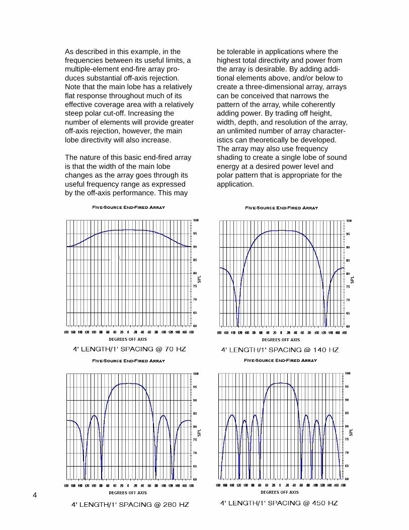
Consider a five-element end-fire line-array with a spacing of 1 foot. Theoverall length of the array is then fourfeet. At 70 Hz, one-quarter wavelength,the array provides approximately 6dBattenuation, less at lower frequencies. At450 Hz, where the spacing of the arrayis 0.4 times the wavelength, the sidelobes remain suppressed by at least 6dB. Intermediate frequencies of 140 Hzand 280 Hz are also shown to helpdescribe the polar characteristics of thearray.
4
As described in this example, in thefrequencies between its useful limits, amultiple-element end-fire array pro-duces substantial off-axis rejection.Note that the main lobe has a relativelyflat response throughout much of itseffective coverage area with a relativelysteep polar cut-off. Increasing thenumber of elements will provide greateroff-axis rejection, however, the mainlobe directivity will also increase.
The nature of this basic end-fired arrayis that the width of the main lobechanges as the array goes through itsuseful frequency range as expressedby the off-axis performance. This may
be tolerable in applications where thehighest total directivity and power fromthe array is desirable. By adding addi-tional elements above, and/or below tocreate a three-dimensional array, arrayscan be conceived that narrows thepattern of the array, while coherentlyadding power. By trading off height,width, depth, and resolution of the array,an unlimited number of array character-istics can theoretically be developed.The array may also use frequencyshading to create a single lobe of soundenergy at a desired power level andpolar pattern that is appropriate for theapplication.

5
APPLICATIONS
The concept of a forward-steered arrayis to create a three-dimensional array ofloudspeakers and delay the drivers backto a point, line, or plane so that theenergy from those drivers coherentlysums in the direction perpendicular tothe reference. The most challengingaspect of this concept is to create adevice that works well acoustically byitself while retaining the ability to bephysically positioned with other likedevices in a modular system that allowsthem to be steered effectively through-out their band of operation.
JBL has developed three such systems;an 18” subwoofer system – PD 128, a15” LF system – PD 125, and a 12” mid-bass system - PD 162. These systemswere designed to maximize off-axisresponse throughout their band ofoperation. The particular applicationsthey were created for demanded widepatterns – roughly 90 degrees, bothhorizontally and vertically. The currentconfiguration of the PD 128 and PD 162array modules allow for the creation ofarrays with wide or narrow verticalpatterns – depending on the configura-tion of the array.
The PD162 Based Low-Frequency Array:

6
The PD162 array development was aneffort to pack low-frequency devicestogether as tightly as possible in aversatile configuration in order to createarrays that can suit a variety of applica-tions. These arrays generally consist offour or more dual-driver array elementsand are steered at an angle between 0and –90 degrees to the array’s refer-ence axis. The steering is accom-plished by delaying each LF elementback to a reference plane that is normalto the direction that the array is beingsteered. The resulting sound energy ispushed forward, coherently summing inthe direction of aiming and minimizingenergy directed off-axis
The array is designed to be steerable inthe vertical direction. Note that whenthe arrays are steered downward, theapparent spacing between drivers isreduced – a fortuitous event thatpushes the theoretical upper working
frequency limit of the arrays upwards.So that the horizontal polar is kept wide,the horizontal driver to driver spacing isminimized. Horizontally, the array be-haves like a spaced pair of sources.This configuration, when steered at anangle of 35 degrees, creates a polarresponse as shown.
This array was developed for use in anindoor arena at a typical cluster position.Note that the desired coverage sector,from 0 degrees to –90 degrees in thiscase, is covered smoothly with onecontiguous energy lobe. Significantly,there is a very large amount of off-axisrejection. The combination of evenresponse in the seating area and a highamount of off-axis energy attenuationhas the potential of substantially in-creasing the quality of the low-frequencysound by maximizing the direct toreverberant energy.
TWENTY-DRIVER FORWARD STEERED ARRAYSIDE ONE OF A TWO-SIDED ARRAY

7
The energy from each driver sumscoherently in the direction of aiming andexhibits no phase shift or anomaliesthroughout the main energy lobe. Atwenty-driver array as shown can con-servatively develop 112 dB SPL continu-ous at 100 feet. The following responseplot of the PD162 array includes phase(dashed). A zero-degree phase shiftthroughout the main lobe is typical forthese arrays – that is, provided the arrayis not otherwise shaded or filtered on anelement by element basis.
8
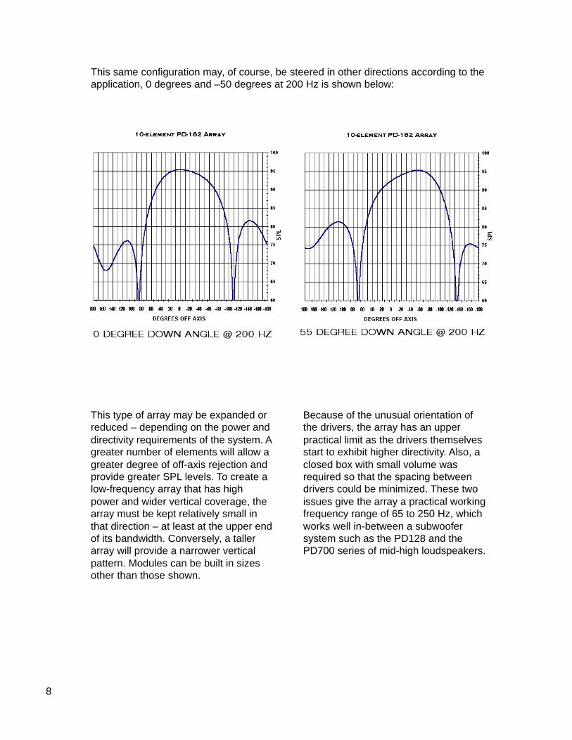
This same configuration may, of course, be steered in other directions according to theapplication, 0 degrees and –50 degrees at 200 Hz is shown below:
This type of array may be expanded orreduced – depending on the power anddirectivity requirements of the system. Agreater number of elements will allow agreater degree of off-axis rejection andprovide greater SPL levels. To create alow-frequency array that has highpower and wider vertical coverage, thearray must be kept relatively small inthat direction – at least at the upper endof its bandwidth. Conversely, a tallerarray will provide a narrower verticalpattern. Modules can be built in sizesother than those shown.
Because of the unusual orientation ofthe drivers, the array has an upperpractical limit as the drivers themselvesstart to exhibit higher directivity. Also, aclosed box with small volume wasrequired so that the spacing betweendrivers could be minimized. These twoissues give the array a practical workingfrequency range of 65 to 250 Hz, whichworks well in-between a subwoofersystem such as the PD128 and thePD700 series of mid-high loudspeakers.

9
The PD 128 Based SubwooferArray:
An array similar in concept has beencreated for use as a subwoofer basedon the PD128 module. Due to theinherent size increase of the elementsand the enclosure a different configura-tion is required. The larger spacing ofthe elements is acceptable since thewavelengths involved are larger. Atthese wavelengths – approximately 8 to32 feet, the shadowing effect of theboxes is not problematic.
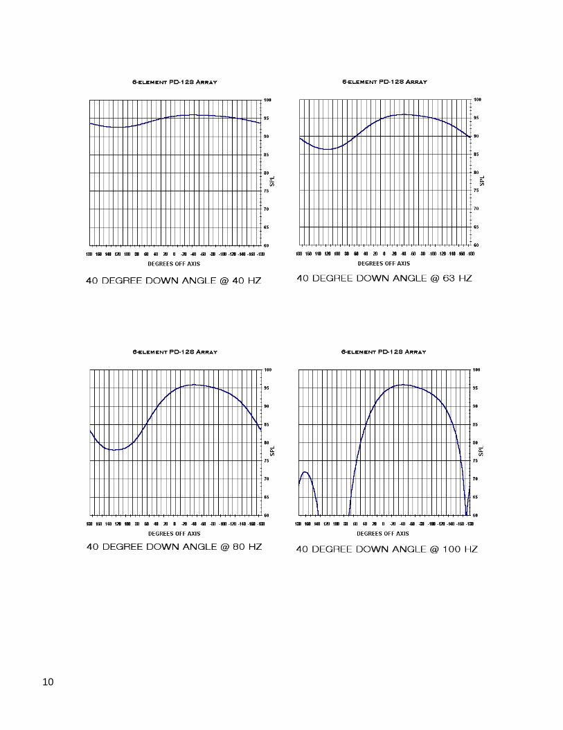
Again, the array is forward-steered atthe angle desired by delaying eachelement back to a plane normal to thedirection of aiming. Due to the geometryof the array, the main lobe will lookslightly different at different steeringangles. This array configuration hasgreater off-axis rejection when steereddownward due to the increase in appar-ent array length. Shown below are six-element arrays at an aiming angle of 40down which is suitable in a typical arenacluster position, working well to coverevenly between 0 and –90 degrees.Note the effectiveness of the steeringand the desirable off-axis rejection.
10

11
The PD 125 High Q Low Frequency Array
The PD125 array module, a dual 15”cabinet, was developed to create arraysthat maximize power response and off-axis rejection while maintaining at leasta 90-degree horizontal coverage patternthroughout its working bandwidth of60Hz to 250 Hz. Its configuration is asimple extension of a multi-element end-fired array.
Frequency Shading:The arrays described have not beentapered or frequency shaded in order tomaintain the maximum available powerthroughout the bandwidth. This alsomaintains the highest total Q of thearray at each frequency. However, it isoften desirable to maintain a moreconsistent polar coverage pattern.Conventional frequency-shading tech-niques may be used to maintain theapparent height of the array with respectto the wavelength and can offset theinherent pattern narrowing at higherfrequencies. This is especially appli-cable to the PD 162 arrays.
Over/Under Delay:By scaling the delay time calculated forthe drivers, the resultant lobe andassociated off-axis attenuation may bemanipulated. As described above, thebasic driver delays are calculated byreferencing them to a plane normal tothe direction of aiming. Using “over-delay”, that is, scaling these delay timesby a factor greater than 1, createsgreater attenuation near the lowerworking limit at the expense of loweringthe upper working frequency. Con-versely, “under-delaying”, or multiplyingthese numbers by a number less than 1,will extend the upper working frequencyat the expense of poorer low-frequencyperformance. Also, using under-delayhas the sometimes-favorable side effectof widening the main lobe at the higherfrequencies.

12
Shown are plots of the same subwoofer arrays described above over-delayed by afactor of 1.3 at 63 and 100 Hz. The off-axis rejection is greater at 63 Hz at the expenseof higher side lobes at 100 Hz.
SUMMARYThere are several advantages of forward-steered arrays. Using only delay between theloudspeaker elements creates high-powered arrays that coherently sum on axis whileproviding a high degree of off-axis rejection. Through the optional addition of frequencyshadings, solutions can be devised to further improve the consistent polar coverage ofthe main lobe of energy or otherwise optimize its response. The systems are alsoextensible as can be put together in a large number of physical configurations depend-ing on the application. And, in addition to the technical features of the arrays described,the arrays are compact with respect to their output power capabilities.
These arrays provide a powerful alternative to conventionally configured low-frequencysystems and have a unique set of capabilities. These configurations may also becustomized and expanded to address and refine a great variety of applications.
1 Olson, H. F., Acoustical Engineering, Copyright 1991, Professional Audio Journals, Inc. p. 38-39 (firstpublished by D. Van Nostrand Company, Inc., 1957).
TN Vol 1 No 288/28/01
JBL Professional8500 Balboa BoulevardNorthrdge, California 91329 U. S. A.