Steam Blowing
25
By: Dhruv Garg Engineer/ Boiler/ PS-TS
description
presentation
Transcript of Steam Blowing
By: Dhruv Garg
Engineer/ Boiler/ PS-TS

Hydraulic Test (Drainable and Non-Drainable portions of pressure parts)
Trial Run of Equipments(Fans – PA, FD, ID, Scanner, Seal Air & Air heaters)
All Gates and Dampers Commissioning
Air and Gas Tightness Test (Furnace, 2nd pass, ESP, air & flue gas ducts)
Fuel Oil System Readiness(LDO / HFO Pumps, Steam Blowing and Oil Flushing of oil lines)
Control and Isolation Valves commissioning (Motorized & Pneumatic)
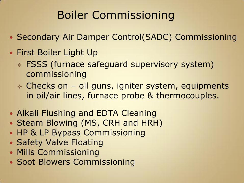
Secondary Air Damper Control(SADC) Commissioning
First Boiler Light Up
FSSS (furnace safeguard supervisory system) commissioning
Checks on – oil guns, igniter system, equipments in oil/air lines, furnace probe & thermocouples.
Alkali Flushing and EDTA Cleaning Steam Blowing (MS, CRH and HRH) HP & LP Bypass Commissioning Safety Valve Floating Mills Commissioning Soot Blowers Commissioning
In spite of doing pre-operational chemical cleaning of the circulation system. certain quantity of debris in the form of scales, loose materials, weld spatter, etc will remain in the boiler tubes & the pipe lines especially in the Superheater coils, Reheater coils, Main steam line, Cold and Hot Reheat Lines.
Subsequent steam blowing completes the task of providing a cleaner system for passing steam into the turbine. In other words we attain steam of required quality standard by way of chemical cleaning, steam blowing and steam dumping method
Failure to remove debris may result in increased turbine erosion, blade damage and rapid deterioration of turbine efficiency.
Puffing Method
Continuous Blowing method
Puffing Method
The system (surfaces) to be clean is first pressurized by steam up to 40-50 kg/cm2 pressure and then releasing of this pressure upto 20-25 kg/cm2 into the atmosphere suddenly caused the cleaning of system internal surfaces, due to high kinetic velocity attained by steam.
Continuous Blowing Method
The surface to be clean is continuously blown by superheated steam for 20-30 min at 12 kg/cm2 & 300-350 0C parameters with cooling down period of 1.5 hrs.
Drum outlet to Final Super-heater header.
Main steam line up to HP Turbine inlet.
Cold Reheat line up to Re-heater inlet.
Re-heater Coils & Headers.
Hot Reheat Line up to IP turbine inlet.
HP and LP bypass Lines.
All Auxiliary steam lines.
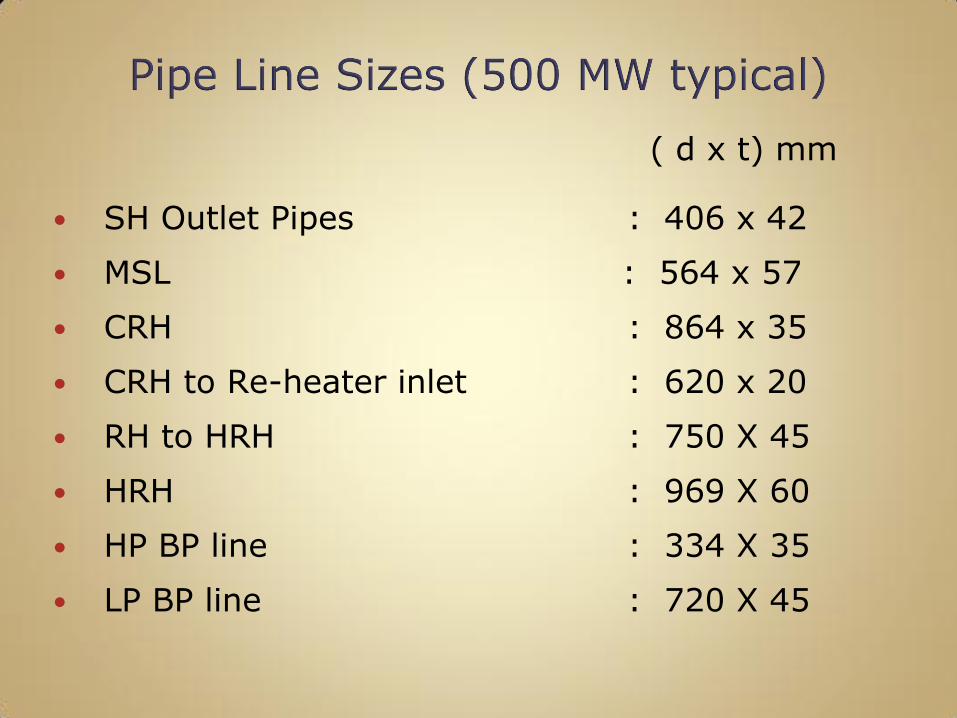
( d x t) mm
SH Outlet Pipes : 406 x 42
MSL : 564 x 57
CRH : 864 x 35
CRH to Re-heater inlet : 620 x 20
RH to HRH : 750 X 45
HRH : 969 X 60
HP BP line : 334 X 35
LP BP line : 720 X 45
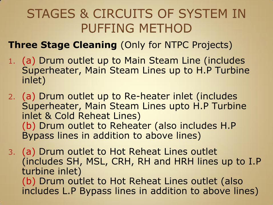
Three Stage Cleaning (Only for NTPC Projects)
1. (a) Drum outlet up to Main Steam Line (includes Superheater, Main Steam Lines up to H.P Turbine inlet)
2. (a) Drum outlet up to Re-heater inlet (includes Superheater, Main Steam Lines upto H.P Turbine inlet & Cold Reheat Lines)(b) Drum outlet to Reheater (also includes H.P Bypass lines in addition to above lines)
3. (a) Drum outlet to Hot Reheat Lines outlet (includes SH, MSL, CRH, RH and HRH lines up to I.P turbine inlet)(b) Drum outlet to Hot Reheat Lines outlet (also includes L.P Bypass lines in addition to above lines)
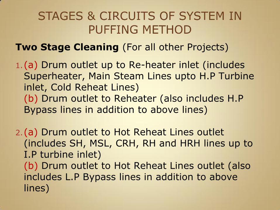
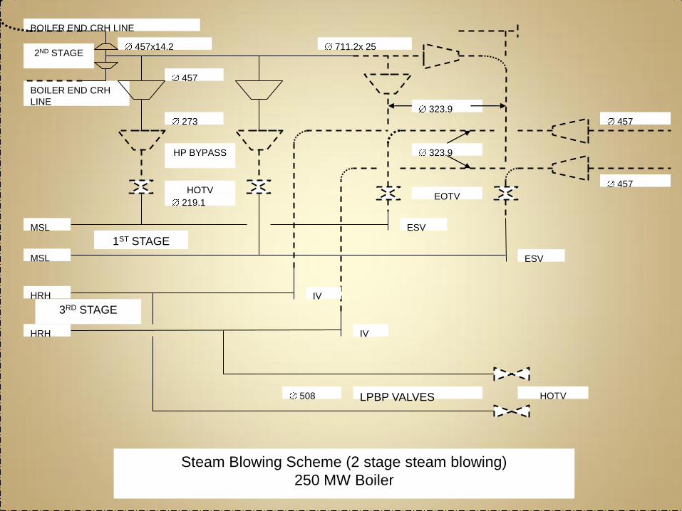
Two Stage Cleaning (For all other Projects)
1.(a) Drum outlet up to Re-heater inlet (includes Superheater, Main Steam Lines upto H.P Turbine inlet, Cold Reheat Lines)(b) Drum outlet to Reheater (also includes H.P Bypass lines in addition to above lines)
2.(a) Drum outlet to Hot Reheat Lines outlet (includes SH, MSL, CRH, RH and HRH lines up to I.P turbine inlet)(b) Drum outlet to Hot Reheat Lines outlet (also includes L.P Bypass lines in addition to above lines)
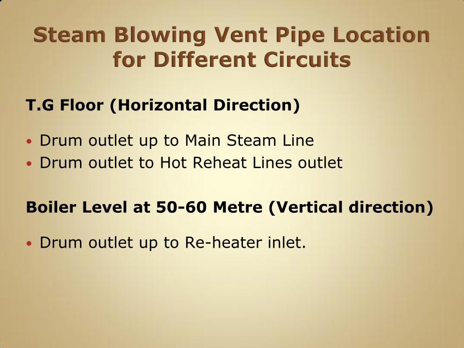
T.G Floor (Horizontal Direction)
Drum outlet up to Main Steam Line
Drum outlet to Hot Reheat Lines outlet
Boiler Level at 50-60 Metre (Vertical direction)
Drum outlet up to Re-heater inlet.
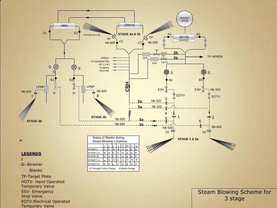
LEGENDS:
S- Strainer
Blanks
TP-Target Plate
HOTV- Hand Operated Temporary Valve
ESV- EmergancyStop Valve
Steam Blowing Scheme for 3 stage
EOTV-Electrical Operated Temporary Valve
BOILER
DRUM
SH O/L HEADER
CRH I/LHRH
Nb 600
Nb 600
Nb 600 Nb 600
LPBP LPBP
2a
2a
Nb 320
Nb 320
3a
3a
Nb 600 Nb 600
TP TP
TPTP
Nb 600 Nb 600
2b
2b
ESV ESV
EOTV EOTV
Nb 320
S
S S SS
E1 E2
IV IV
STAGE 2a & 2b STAGE 2a & 2b
STAGE 1 & 3a
STAGE 3b
STAGE 3b
C1 C2
B1 B2
A1 A2D1 D2
TP APRDS
7 8
APRDS
TO DEAERATOR
HE 1,2 & 5
TO BFPS
(4a & 4b)
CR
H
5
4
3
16
2
HOTV
HOTV
SPP
SPP
87654321
B B B B B B
B B BBBB
B B
B
B B B
B
B
B
B
B B
B
O O
OO
O O
O O
O O O O
B
O O
STAGE 1
STAGE 2 a
STAGE 2b
STAGE 3 a
STAGE 3 b
Status of Blanks during
Steam Blowing Locations 87654321
B B B B B B
B B BBBB
B B
B
B B B
B
B
B
B
B B
B
O O
OO
O O
O O
O O O O
B
O O
STAGE 1
STAGE 2 a
STAGE 2b
STAGE 3 a
STAGE 3 b
Status of Blanks during
Steam Blowing Locations
O-Through Orifice Flange B-Blank Flange
LPBP VALVES
IV
IV
ESV
ESV
EOTVHOTV
HRH
MSL
BOILER END CRH
LINE
BOILER END CRH LINE
457x14.2
457
457
323.9
1ST STAGE
2ND STAGE
3RD STAGE
Steam Blowing Scheme (2 stage steam blowing)
250 MW Boiler
HP BYPASS
508
219.1
273
457
323.9
711.2x 25
MSL
HRH
HOTV
The boiler is to be lighted up in a normal manner, following start up procedure from Boiler O&M manual.
Boiler drum pressure raised to 40 – 50 kg/sq.cm.
Water level in the drum kept at the lowest port (visible limit) before the start of each steam blow off.
The lines to be blown is charged slowly with steam using the Main Stop Valve bypass lines and warmed up for 30 mins, keeping all the drains in open condition to avoid hammering.
Test Blow at 25 kg/ sq.cm pressure up to 15 kg/ sq.cm to be given first before start of each stage of steam blowing to ensure the system healthiness.
Light off the Boiler at the specified drum pressure & at the same time, open the valve (Electrically Operated Travelling Valve) for sudden release of pressure in the flow of steam through all pressurized pipelines into the atmosphere.
Close this valve at a pressure of 20-25 kg/sq. cm. Also ensure that, fall in the drum metal temp. is not going to exceeds above 40-45 deg C to avoid thermal stress in the metal.
Limit number of blows per day to 8 with an interval of 1 ½ hours for cooling in addition to overnight cooling.
(Typical Steam blowing starting time at 0600 hrs and end time at 2200hrs)
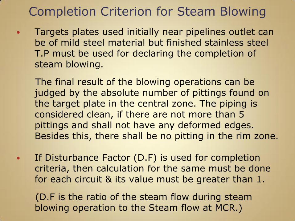
Targets plates used initially near pipelines outlet can be of mild steel material but finished stainless steel T.P must be used for declaring the completion of steam blowing.
The final result of the blowing operations can be judged by the absolute number of pittings found on the target plate in the central zone. The piping is considered clean, if there are not more than 5 pittings and shall not have any deformed edges. Besides this, there shall be no pitting in the rim zone.
If Disturbance Factor (D.F) is used for completion criteria, then calculation for the same must be done for each circuit & its value must be greater than 1.
(D.F is the ratio of the steam flow during steam blowing operation to the Steam flow at MCR.)
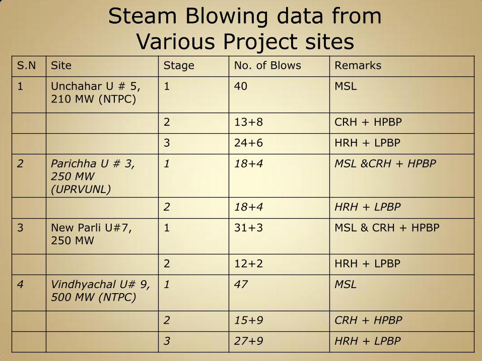
S.N Site Stage No. of Blows Remarks
1 Unchahar U # 5, 210 MW (NTPC)
1 40 MSL
2 13+8 CRH + HPBP
3 24+6 HRH + LPBP
2 Parichha U # 3, 250 MW (UPRVUNL)
1 18+4 MSL &CRH + HPBP
2 18+4 HRH + LPBP
3 New Parli U#7, 250 MW
1 31+3 MSL & CRH + HPBP
2 12+2 HRH + LPBP
4 Vindhyachal U# 9, 500 MW (NTPC)
1 47 MSL
2 15+9 CRH + HPBP
3 27+9 HRH + LPBP
To remove debris, scales and weld splatters and clean the internal surface of oil lines in the LDO / HFO system including atomizing steam lines and steam tracing lines.
The Fuel oil plant consists of facilities for Unloading, Storage and Supply of LDO and HFO.
Fuel Oil Pump House is located close to Fuel Storage Yard.
The Pump house houses:
LDO and HFO Pumps for Main Boiler HFO Heaters HFO cooler in the return line Drain Oil Tank & Drain Pump Electrical & control Panels for FO Pump House
auxiliaries
The line to be blown is charged slowly with auxiliary steam and warmed up, keeping the drains open.
After proper charging , blow is given for 20-30 minutes.
Steam at a pressure of 10-12 Kg/cm2 and having a superheat of at least 350 deg C at source is used for blowing.
The line is allowed to cool for 1-2 hours and then again blown.
Blowing of drains, vents and instrument tapping points is done at 5 Kg/cm2 for 10 minutes each.
Blowing of LDO lines, Steam tracing lines and condensate lines is done at 6 Kg/cm2 for 20-30 minute each.
Drains / vents of FO lines are kept open as required during steam blowing and thereafter for draining of condensate.
After sufficient cooling, the piping are dried with compressed air.
After completion of steam blowing, all spool pieces are removed and Trip valves, control valves, flow elements, filter elements and NRV internals are restored / normalized. Pipe connections to LDO / HFO pumps are normalized and pumps are commissioned.
Steam blowing of the section of LDO / HFO lines is declared complete after minimum five blows each having a blow duration of 20-30 minutes.
Blowing medium at exit of the pipe should be visually clean.