WELCOME TOPIC- STEAM BLOWING By- Operation Team ADANI POWER MAHARASHTRA LTD,TIRODA, 5 X 660 MW.
49
WELCOME TOPIC- STEAM BLOWING By- Operation Team ADANI POWER MAHARASHTRA LTD,TIRODA, 5 X 660 MW
-
Upload
laureen-shaw -
Category
Documents
-
view
240 -
download
6
Transcript of WELCOME TOPIC- STEAM BLOWING By- Operation Team ADANI POWER MAHARASHTRA LTD,TIRODA, 5 X 660 MW.
WELCOME
TOPIC- STEAM BLOWINGBy- Operation Team
ADANI POWER MAHARASHTRA LTD,TIRODA,5 X 660 MW

INTRODUCTIONPURPOSE :
Steam blowing of MS lines, CRH,HRH,SH,RH,HP & LP bypass pipe lines of turbine is carried out in order to remove welding slag, loose foreign materials, iron pieces, rust etc. from the system, generated during manufacturing, transportation & erection.
EFFECT OF BLOWING DEPENDS ON
1) Thermal shock2) Removal force of steam3) Cleaning force of steam

REMOVAL FORCE OF STEAM
Blowing Mass Flow ,Q flow= √1.25 * Qmcr √(Vmcr
/Vblow)
Qmc= mass flow at MCR
Vmc= velocity at MCR
Vblow=blowing velocity
CLEANING FORCE OF STEAM
The necessity to create in the system, the steam velocity greater than that is possible at MCR condition is obvious. These two velocities are expressed as a ratio “Cleaning factor” or “ Distribution factor” or “Cleaning Force Ratio” denoted by “X” or “K”.

CLEANING FORCE REQUIRED (CFR)OR DISTRIBUTION FACTOR
a) K=Velocity of steam during blowing / Velocity of steam at MCR
b) K= (Steam flow during blowing)2 *(Sp.vol of steam at blowing
(Steam flow at MCR)² * ( Sp.vol of steam at MCR)
Steam flow can be measured by the net feed water flowCFR & velocities of the steam should be verified to avoid
“Over Blowing”The recommended value K > 1.25 ( between 1.25 and 1.4)
PRECONDITIONS FOR STEAM LINE BLOWING1) Chemical cleaning should be completed2) SH primary and secondary de-superheater
piping and RH’s emergency de-superheater piping ready for operation
3) All permanent piping & temporary piping insulated and supports/hangers are released with cold setting
4) Silencer should be connected at temporary pipe exit
5) Soot blowing for APH should be available6) Make up for deaerator made ready7) Motor Driven BFP with all controls made
ready
PRECONDITIONS …
7) Hydraulic test of the following lines completed:
Feed Lines MS, HRH, CRH Lines MS to Aux. PRDS Line All other auxiliary lines identified for
steam blowing 8) Sampling system made ready

PRECONDITIONS …
9) Boiler auxiliaries proved serviceable and ready after pilot operation like:
- Fuel oil system- Compressors & Atomizing steam system- Start-up system ( for continuous system)- Coal Mill system (for continuous system)- CHP readiness- Economizer hopper and bottom ash hopper
and its evacuation system (for continuous system)
PRECONDITIONS …10) All safety valve disc installed after
removing hydro-static plug in drum(sub-critical), superheaters and reheaters
11) Adequate communication between control room, boiler and TG area ensured.
12) Flow nozzle, control valves and NRV flaps wherever applicable should be not erected before steam blowing and suitable spool pieces are erected. Strainers in the path should be removed.
13) Required number of Target Plates and holder made available
CHEMICAL CLEANING PROCESS
BOILER FRONT SYSTEM ALKALINE FLUSHING Mass Flushing Hot water Rinsing Alkaline Flushing Hot DM water Rinsing
MAIN BOILER SYSTEM ACID CLEANIG Super Heater Filling Mass Flushing Alkaline Flushing Hot DM water Rinsing Acid Cleaning Passivation

CHEMICAL CLEANING …ACID CLEANING ( BY CITRIC ACID METHOD )will be
done by circulation method for effectiveness of the cleaning process.
Acid cleaning will be followed by PASSIVATION, so that the uniform protective coating of GAMMA FERRIC OXIDE is formed on the metal surface and corrosion / oxidation damage to metal surface is prevented and continue during normal operation by dosing oxygen. The gamma ferric Oxide formed by using the chemical 1-2 % sodium Nitrite(NaNO2)
BASIC TECHNIQUE USED
1) PUFFING METHOD
2) PURGING METHOD / CONTINEOUS BLOW METHOD
PUFFING METHOD
To give a thermal shock to the contour being purged, to dislodge the scale etc.
Procedure: Raise the boiler pressure to a pre-determined value (40-60 kg/cm2), shut off firing and at the same time open the quick opening valve(EOTV), thus allowing the steam to escape to atm. with high velocity carrying with it the loose debris.
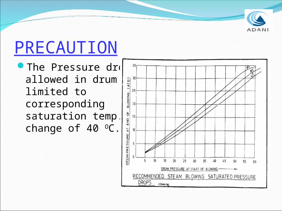
PRECAUTIONThe Pressure drop
allowed in drum is limited to corresponding saturation temp. change of 40 OC.
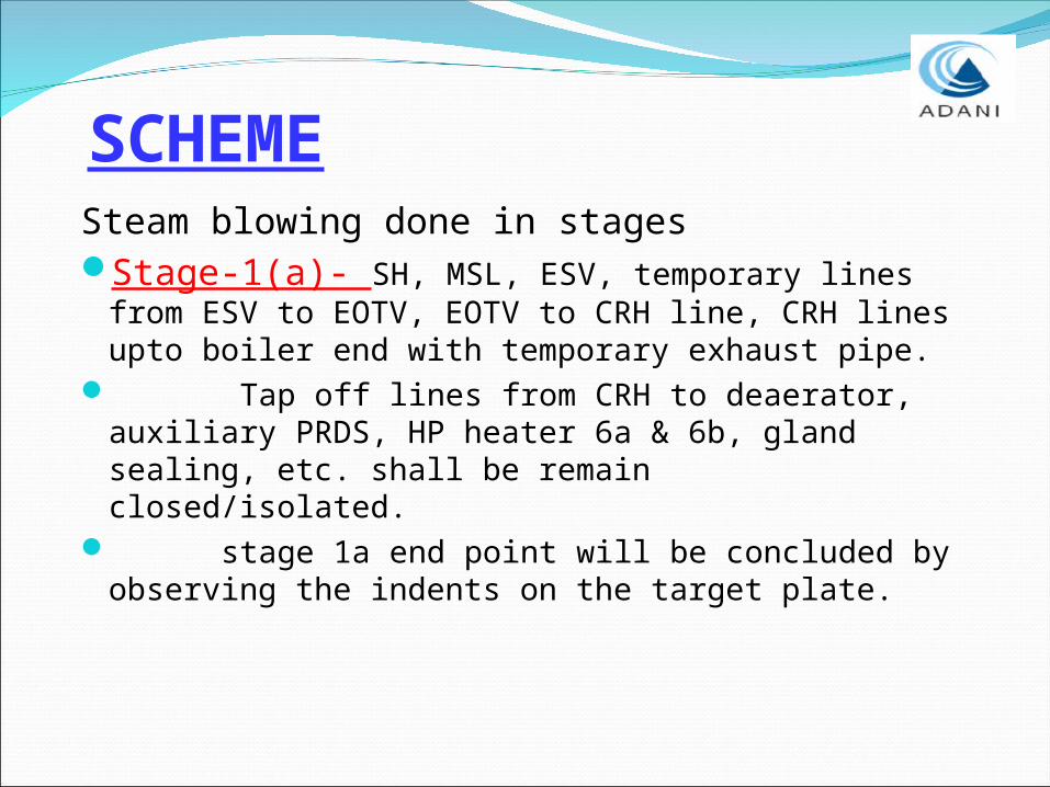
SCHEMESteam blowing done in stagesStage-1(a)- SH, MSL, ESV, temporary lines
from ESV to EOTV, EOTV to CRH line, CRH lines upto boiler end with temporary exhaust pipe.
Tap off lines from CRH to deaerator, auxiliary PRDS, HP heater 6a & 6b, gland sealing, etc. shall be remain closed/isolated.
stage 1a end point will be concluded by observing the indents on the target plate.

STAGE- 1(a)
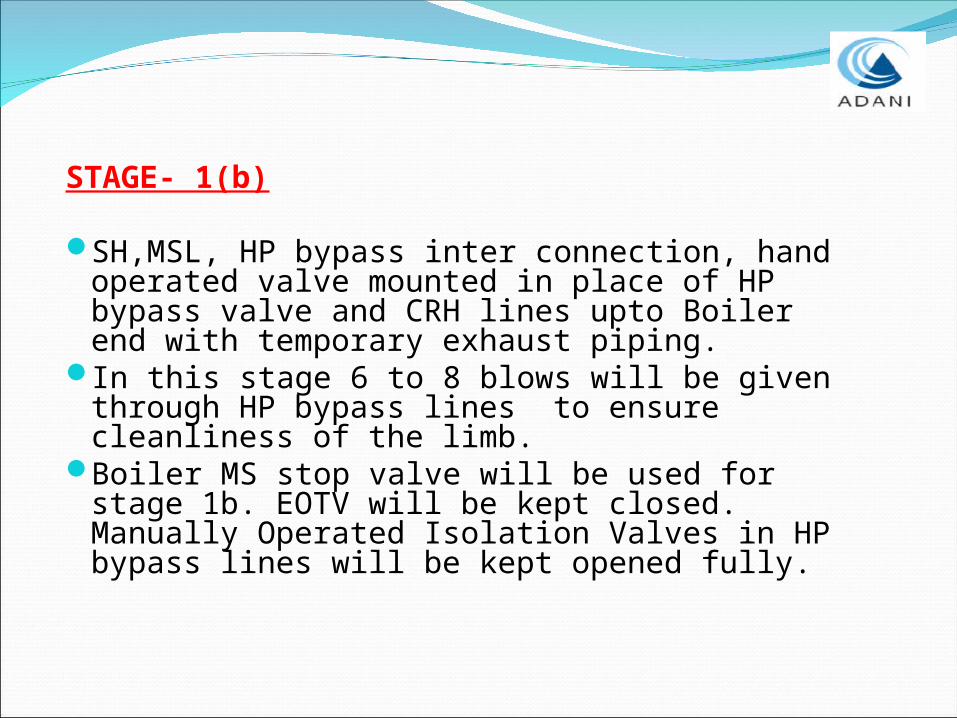
STAGE- 1(b)
SH,MSL, HP bypass inter connection, hand operated valve mounted in place of HP bypass valve and CRH lines upto Boiler end with temporary exhaust piping.
In this stage 6 to 8 blows will be given through HP bypass lines to ensure cleanliness of the limb.
Boiler MS stop valve will be used for stage 1b. EOTV will be kept closed. Manually Operated Isolation Valves in HP bypass lines will be kept opened fully.

STAGE- 1(b)
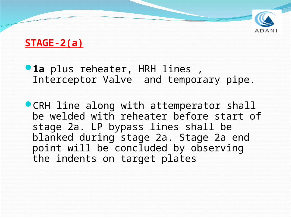
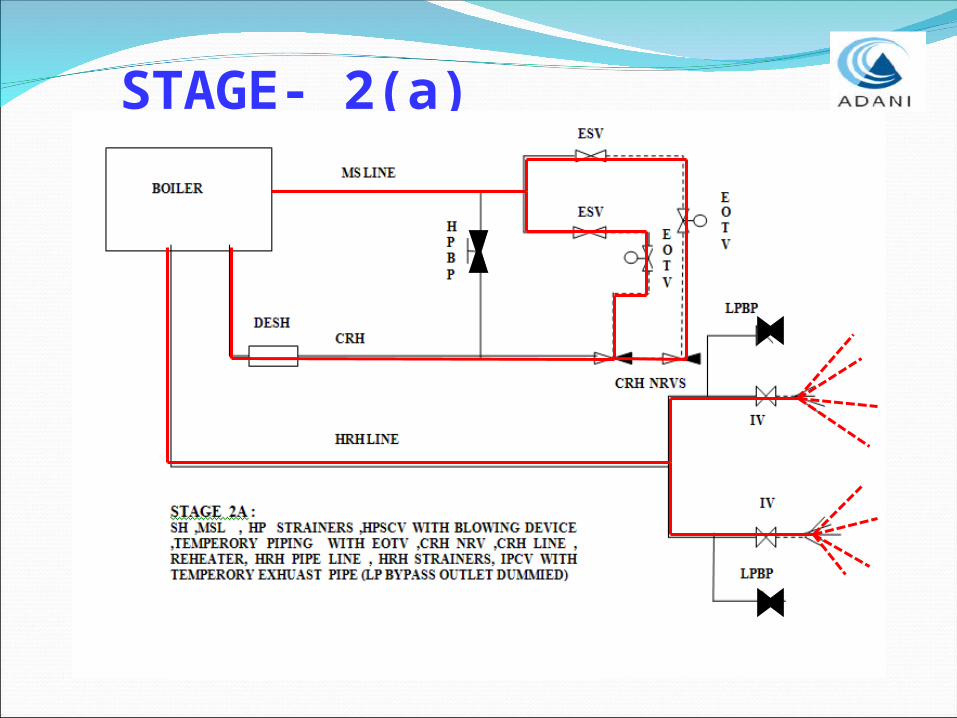
STAGE-2(a)
1a plus reheater, HRH lines , Interceptor Valve and temporary pipe.
CRH line along with attemperator shall be welded with reheater before start of stage 2a. LP bypass lines shall be blanked during stage 2a. Stage 2a end point will be concluded by observing the indents on target plates
STAGE- 2(a)
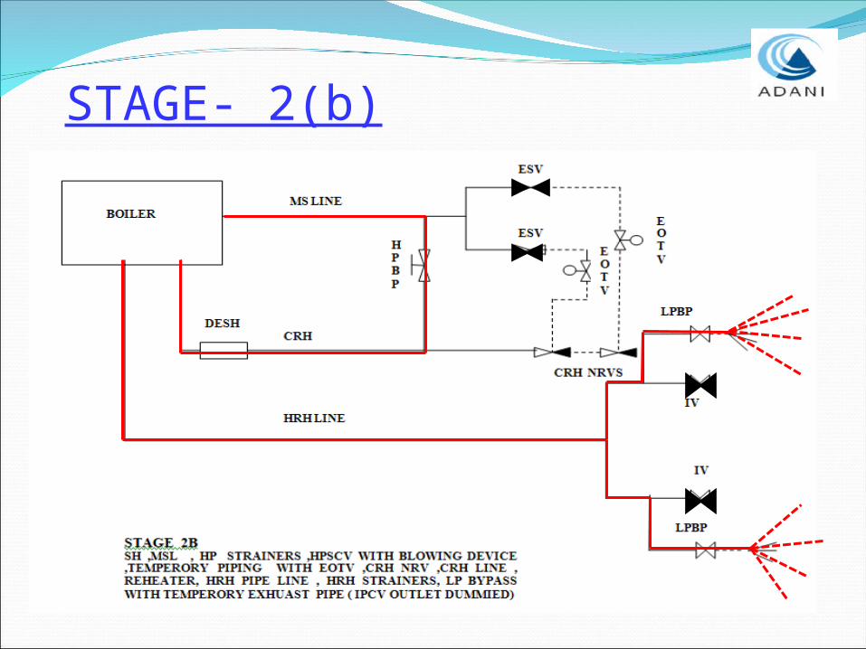
STAGE- 2(b)
2a upto IV + LP bypass lines with temporary exhaust pipe.
Stage 2b blowing will be parallel blow in the path 2a & 2b. LP Bypass blanks shall be removed for stage 2b. 4 blows will be given through L.P. Bypass line to ensure cleanliness of the limbs
STAGE- 2(b)
STAGE-3
Auxiliary Steam Lines covered in steam blowing are listed below.
3a) Main steam line to Aux PRDS3b) CRH to Deaerator3c) CRH to HPH-6.All auxiliary steam lines will be steam
blown by continuous blowing method
STAGE-4
The following Aux steam lines, connected to deaerator are steam blown using auxiliary steam from Aux PRDS header.
4a)PRDS to Deaerator.
4b)Extraction 4 to Deaerator. 4c) PRDS to Gland steam header.
CONTINEOUS BLOWING METHODThe initial procedure is same as puffing
method except:
- Continuous firing till the completion of steam blowing. No need to shut of the firing during blowing.
- Maintain constant pressure during the blow
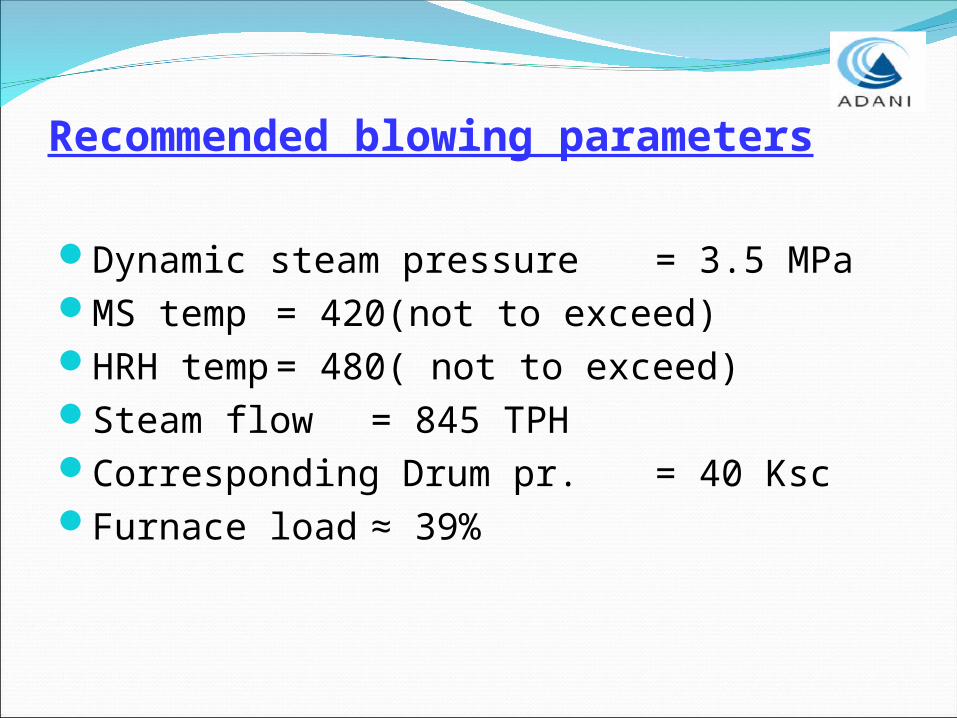
Recommended blowing parameters
Dynamic steam pressure= 3.5 MPaMS temp = 420(not to
exceed)HRH temp = 480( not to
exceed)Steam flow = 845 TPHCorresponding Drum pr. = 40 KscFurnace load ≈ 39%
METHOD- Set the Temporary purging valve, by-pass
valve and drain valve and granulating device behind the temporary pipes
- Check the tightness, support and expansion of the temporary system
- Section by section rinse of condensate water piping, feed water piping and boiler through the start-up system to CW system
METHOD: - Circulation begins when Fe+ in the water
of main feed water pipe and separator outlet will be less than 100 ppm.
- Maintain the circulation flow or start-up flow at minimum set value
- Start oil firing and raise the temp and press. according to the cold start-up.
Temp. rise rate of water wall = less than 2OC / min
Temp. rise rate of main steam = 4 ~ 5 OC / min
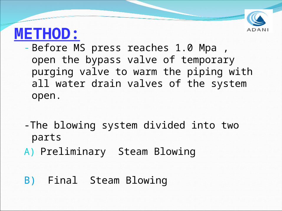
METHOD:- Before MS press reaches 1.0 Mpa , open
the bypass valve of temporary purging valve to warm the piping with all water drain valves of the system open.
-The blowing system divided into two partsA) Preliminary Steam Blowing
B) Final Steam Blowing
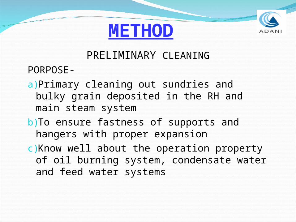
PRELIMINARY CLEANING
PORPOSE-a)Primary cleaning out sundries and bulky
grain deposited in the RH and main steam system
b)To ensure fastness of supports and hangers with proper expansion
c)Know well about the operation property of oil burning system, condensate water and feed water systems
METHOD

PRELIMINARRY STEAM BLOWING- Start the oil firing with max. rating of 15% - Control the gas temperature at furnace
outlet below 500 OC (max.538 OC )- Raise the SH outlet press to 1.6 – 1.8 Mpa
with steam temperature around 350 OC.- Open the temporary purging valve for 15-
20 min to blow in MS system- Maintain K around 0.5.- SH & RH desuperheater water system also
cleaned
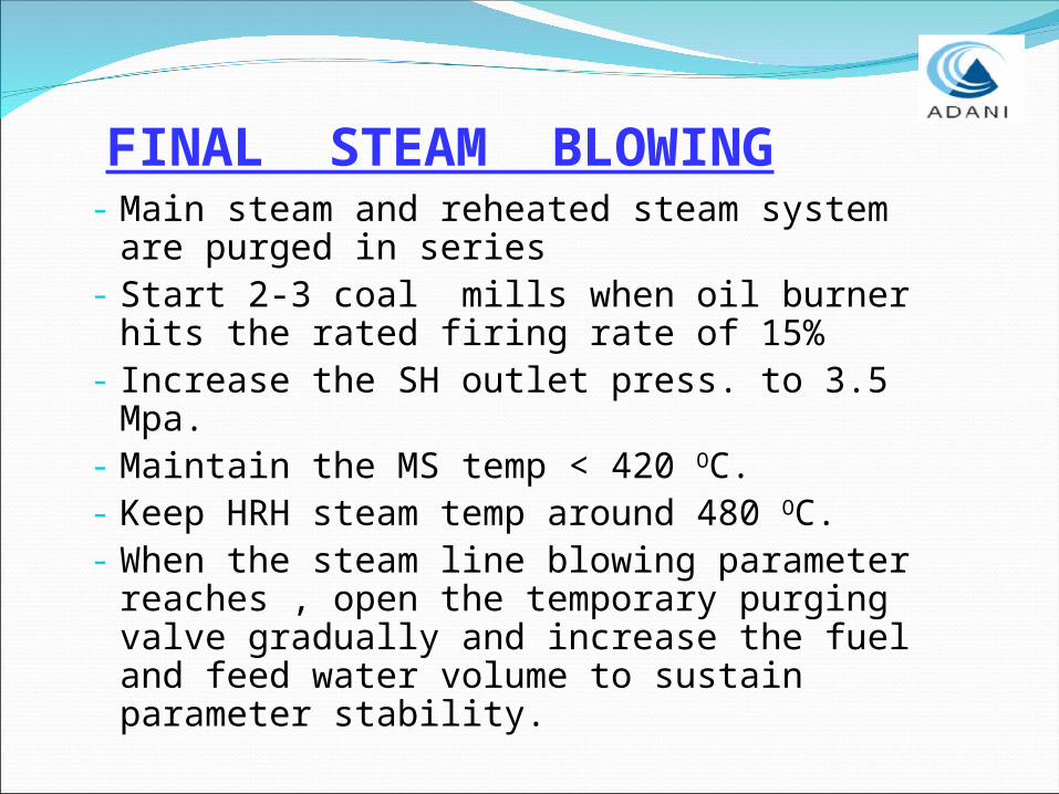
FINAL STEAM BLOWING- Main steam and reheated steam system
are purged in series- Start 2-3 coal mills when oil burner hits
the rated firing rate of 15%- Increase the SH outlet press. to 3.5 Mpa.- Maintain the MS temp < 420 OC.- Keep HRH steam temp around 480 OC.- When the steam line blowing parameter
reaches , open the temporary purging valve gradually and increase the fuel and feed water volume to sustain parameter stability.
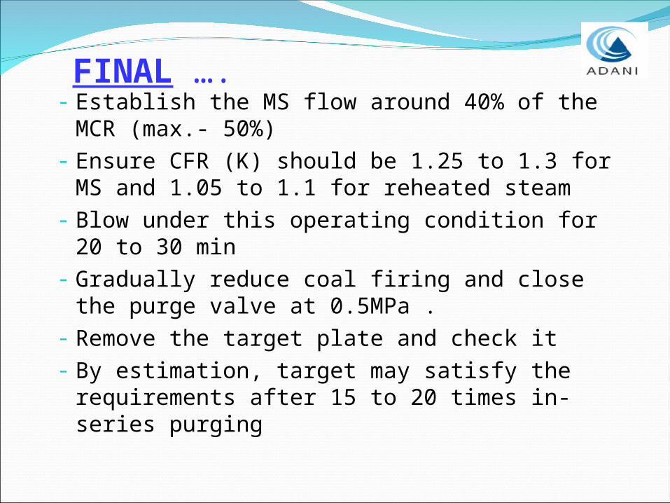
FINAL ….- Establish the MS flow around 40% of the
MCR (max.- 50%)- Ensure CFR (K) should be 1.25 to 1.3 for MS
and 1.05 to 1.1 for reheated steam- Blow under this operating condition for 20
to 30 min- Gradually reduce coal firing and close the
purge valve at 0.5MPa . - Remove the target plate and check it- By estimation, target may satisfy the
requirements after 15 to 20 times in-series purging
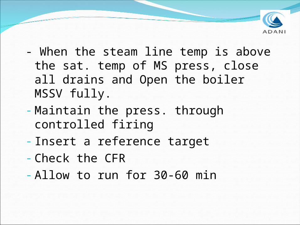
- When the steam line temp is above the sat. temp of MS press, close all drains and Open the boiler MSSV fully.
- Maintain the press. through controlled firing
- Insert a reference target- Check the CFR- Allow to run for 30-60 min
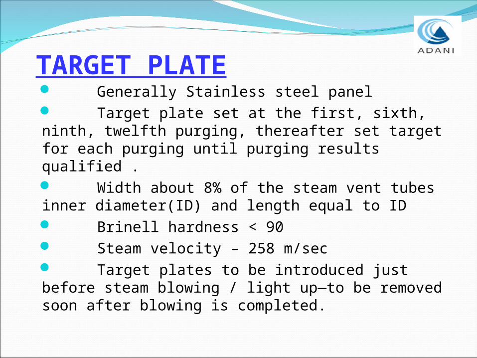
TARGET PLATE Generally Stainless steel panel Target plate set at the first, sixth, ninth, twelfth purging, thereafter set target for each purging until purging results qualified . Width about 8% of the steam vent tubes inner diameter(ID) and length equal to ID Brinell hardness < 90 Steam velocity – 258 m/sec Target plates to be introduced just before steam blowing / light up—to be removed soon after blowing is completed.
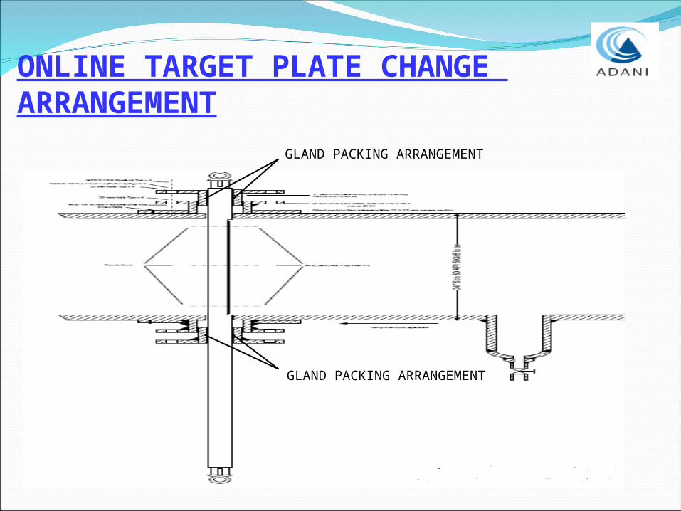
ONLINE TARGET PLATE CHANGE ARRANGEMENT
GLAND PACKING ARRANGEMENT
GLAND PACKING ARRANGEMENT

DEBRIS FILTER

AUX BOILER TO AUX STEAM HEADER
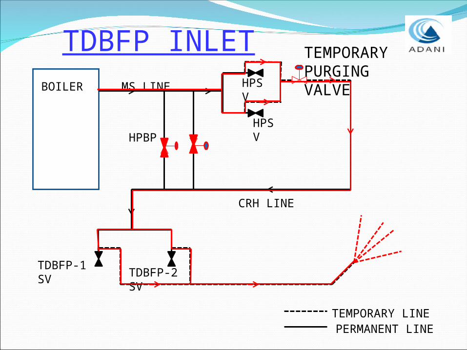
TDBFP INLETBOILER
HPSV
HPSV
TEMPORARY PURGING VALVE
HPBP
TDBFP-1 SV
CRH LINE
MS LINE
TDBFP-2 SV
TEMPORARY LINEPERMANENT LINE
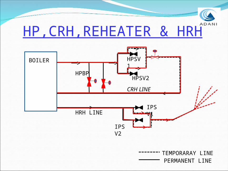
HP,CRH,REHEATER & HRH
BOILER
HPSV2
HPSV1
HPBP
CRH LINE
IPSV1
IPSV2
HRH LINE
TEMPORARAY LINEPERMANENT LINE
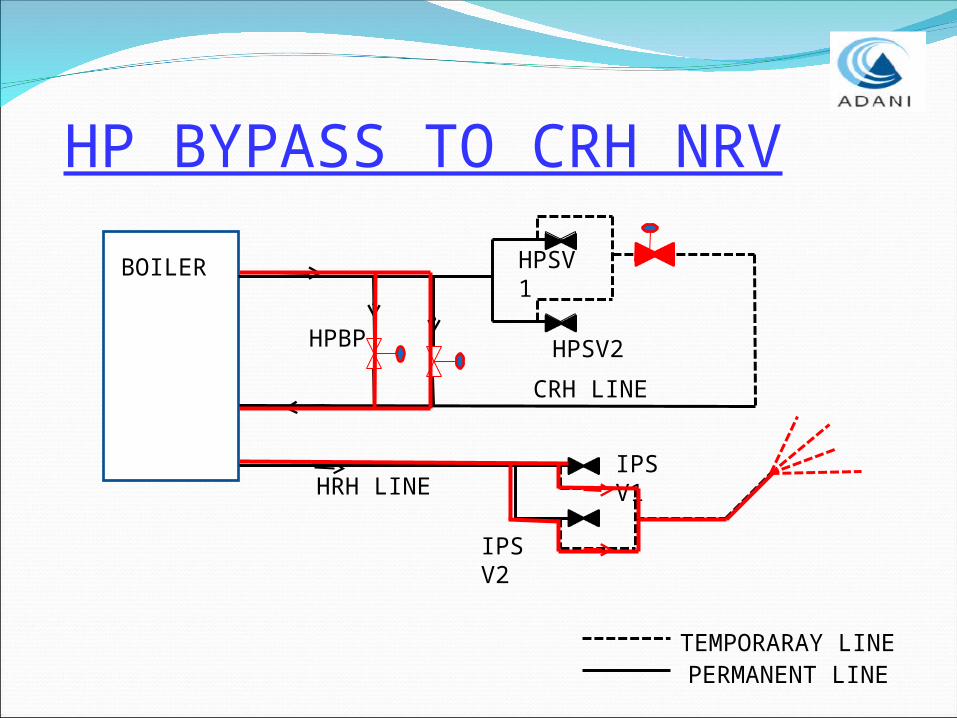
HP BYPASS TO CRH NRV
BOILER
HPSV2
HPSV1
HPBP
CRH LINE
IPSV1
IPSV2
HRH LINE
TEMPORARAY LINEPERMANENT LINE
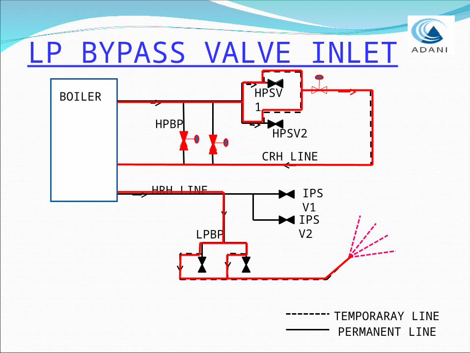
LP BYPASS VALVE INLETBOILER
HPSV2
HPSV1
HPBP
CRH LINE
IPSV1
IPSV2
HRH LINE
LPBP
TEMPORARAY LINEPERMANENT LINE
STEAM BLOWING COMPLETION CRITARIA
At least 2 continuous target plates should not have ORIFICE GRANULARITY on the target shall be not larger than 0.8 mm.
CFR should be 1.25 to 1.4
No. of orifice granularity shall not supass 08 nos.
ADVANTAGES- Required less time for completion of the total
process- Less time required to normalize the system for
final light-up to synchronisation
- This reduces the reactionary forces on the temporary pipes
- Stresses on the boiler system are lower
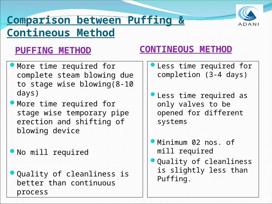
PUFFING METHOD CONTINEOUS METHOD
More time required for complete steam blowing due to stage wise blowing(8-10 days)
More time required for stage wise temporary pipe erection and shifting of blowing device
No mill required
Quality of cleanliness is better than continuous process
Less time required for completion (3-4 days)
Less time required as only valves to be opened for different systems
Minimum 02 nos. of mill required
Quality of cleanliness is slightly less than Puffing.
Comparison between Puffing & Contineous Method
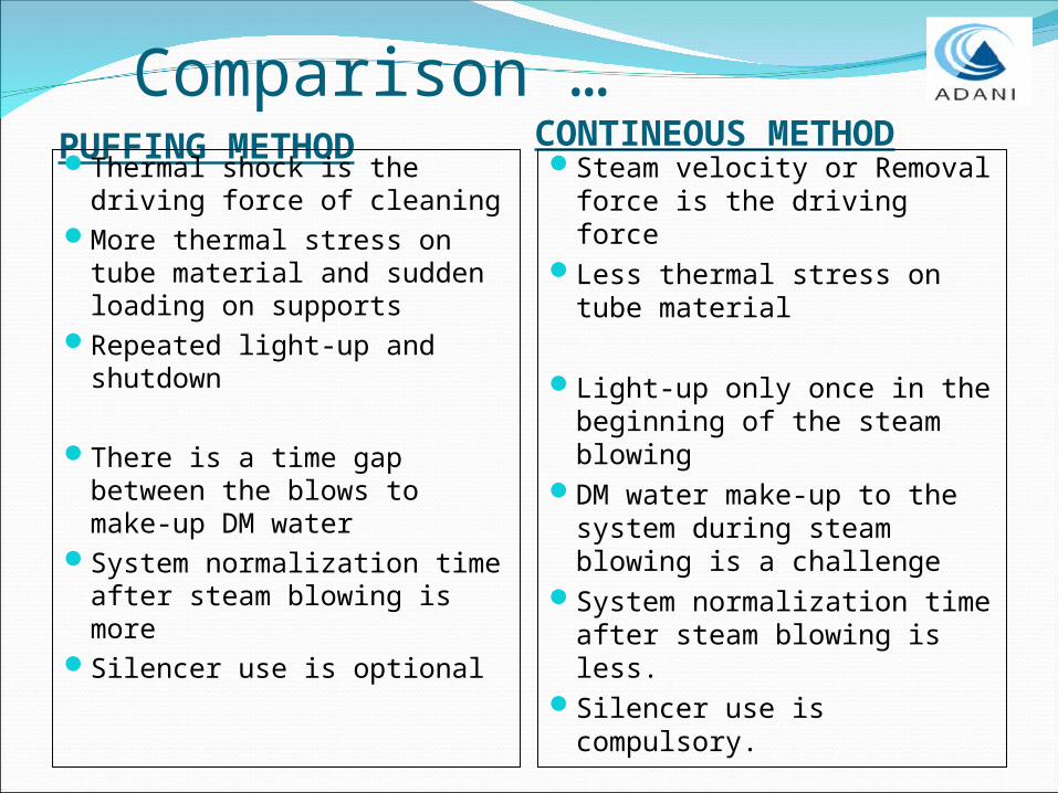
Comparison …PUFFING METHOD CONTINEOUS METHODThermal shock is the
driving force of cleaningMore thermal stress on
tube material and sudden loading on supports
Repeated light-up and shutdown
There is a time gap between the blows to make-up DM water
System normalization time after steam blowing is more
Silencer use is optional
Steam velocity or Removal force is the driving force
Less thermal stress on tube material
Light-up only once in the beginning of the steam blowing
DM water make-up to the system during steam blowing is a challenge
System normalization time after steam blowing is less.
Silencer use is compulsory.


![P567 Not Adani Deal - The Australia Institute Not Adani Deal [WEB]_… · Not Adani Deal Queensland Government subsidies to Adani The Queensland Labor Government has offered Adani](https://static.fdocuments.us/doc/165x107/5edfdb34ad6a402d666b26e7/p567-not-adani-deal-the-australia-institute-not-adani-deal-web-not-adani.jpg)