Statistical Approach to Insulation Coordination INS. COORDINATION Outcomes: 1-selection or...
76
Statistical Approach to Insulation Coordination INS. COORDINATION Outcomes: 1-selection or specification of the Elec. Strength 2-ph. to Gr and Ph. to ph. Clearances & leakage or creepage distance 3-selection of surge arresters
-
Upload
antony-joseph -
Category
Documents
-
view
222 -
download
4
Transcript of Statistical Approach to Insulation Coordination INS. COORDINATION Outcomes: 1-selection or...

Statistical Approach to Insulation Coordination
INS. COORDINATION Outcomes: 1-selection or specification of the Elec.
Strength
2-ph. to Gr and Ph. to ph. Clearances &
leakage or creepage distance 3-selection of surge arresters

Suggested Steps (air insulated Substations)
1-rating of surge arrester
2-creepage length of porcelain insulator
(contamination & Equivalent. BIL & BSL)
3-Arrester close to transformer & its BIL, BSL
4-BIL of other Equipments & ph. to Gr clearance, lightning O.V.s (if BIL & clearance excessive, New Arr. & the BIL again.) 5-BSL of other equipment, ph. to Gr. & ph. to ph. Clearances (required by switching OV.s) 6-Protection of opened CCT. Breaker (gap type or arrester)

Insulation coordination approach
Ins. Design of substation equipments ◊Transformer as an Example: 1-highest surges enter substation/generate within it 2-stress on coil-to-coil & turn-to-turn INS. 3-INS. Sys. need capability of 20% above calculated 4-Surge arrester rating coordinated with Transformer
INS.
Safety factors employed: to cover lack of knowledge
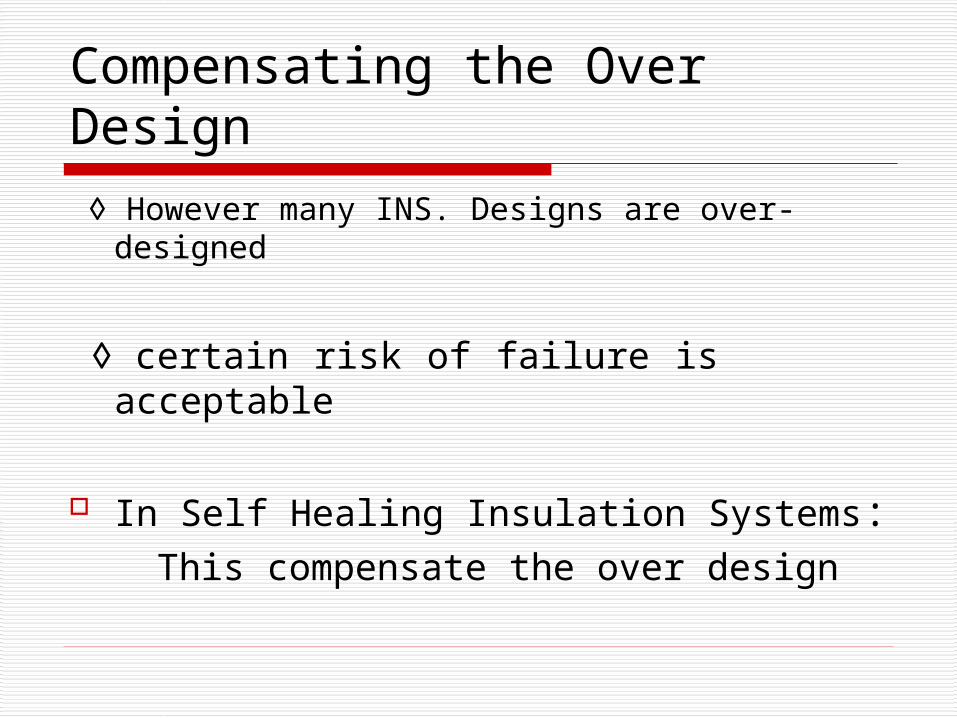
Compensating the Over Design
◊ However many INS. Designs are over-designed
◊ certain risk of failure is acceptable
In Self Healing Insulation Systems: This compensate the over design

Probabilistic Nature of voltage stress & Insulation strength
Insulation of O/H line :1-reducing No. of insulators: save money; cost risk; reduce cross arm
length, width of right of way, weight of tower; affect foundation
2-to justify this change, risk should be quantified
3-INS. Strength Determined by R.O.F.

Parameters for Risk Assessment
◊stress has a f(Va) of Normal Dis.
◊ F(va) prob. of Voltage less than Va
◊ Q(Va) prob. of Voltage exceed Va
Breakdown Strength of Ins. Also Statistic

Risk of Insulation Failure
Matching probabilities of Insulation stress & strength, risk of failure determined
Prob. of flashover g(Vw) & its cum. G(Vw)
then prob. of V1 occur : f(V1)
prob. Flashover at less than V1, G(V1) ◊ prob. of V1 & flash Over: f(V1)xG(V1)

Risk Assessment Normal Dis. For stress: f(Va)=1/[σs√2Π] exp{-1/2[(Va-S)/σs]} Eq (1)
where:
S: mean σs=standard dev. Surge with crest of S2=S+2σs,
for sw. surge INS. Design
Possibility of a surge exceed S2 ≈ 2%
S2 is referred to as : ”statistical switching overvoltage”

Probability of Failure ◊ Surge known by: f(Va) applied an Ins. Of
CFO & σ
The prob. of flashover can calculated :
from Eq (1) & Eq of Normal Dis. As follows:
21( )21
( )2
TV x CFO
TF V e dx

Risk Assessment continued resultant probability:
Where: y=[S-CFO]/√(σ+σs)
◊ Transmission Lines N elements Prob. At least one flash over:
P(N,V)=1- [1 - P(V)]^N
21( ) exp ( )
22
Y zP V dz f Y

Example of Risk Assessment A line with 500 towers which CFO is 2.3 pu, & σ=4.5% and stress characterized
by: s=1.6 and σs=10% σ= 2.3x0.045=0.1035, σs=0.16 pu Y=[1.6-2.3]/√(0.1035+0.16)=-3.67 P(V)=1.22x10^-4 ignoring neg. surges
P(V)=6.1x10^-5 This is for 1 Tower, for the whole line: P(N,V)={1-[1-0.000061]^500}=3.0x10^-2 means 30 switch op.s per 1000 applications

Protection of Systems and Equipment against Transient OVs
Surges in PWR SYS can be Very destructive Important to protect against them1- stop Lightning surge generated outside to enter2- minimize effects of those entered
3- sw. surges & surges gen. by faults are inevitable, however reduced by proper design How to protect PWR SYS Equip.s and control
CCTs or relays The surge protection devices

Surge Protection Devices & their Application
Ground Wires1- 1 or 2 are bounded to tower above ph. Conductors2- Ground wires are at ground potential under normal 3- lightning strokes stopped to be terminated on ph.
Strike Distance: S (Love’s Formula)1- as a leader stroke approaches earth’s surface, it is attracted
towards tall objects2- s: strike distance ; stroke tip reaches within distance “S” of Gr object prob. of terminating on that > prob. striking another object in a distance more than s
S=10x I ^ 0.65 (I in kA, S in m) EQ.1

Strike Distance Application If I=10 kA, S=44.7 m if I=50 kA, S=127 m Anderson approach α:shielding angle βs: h of horizontal line strokes within βs of Earth terminate on it, rather
than on Gr or ph β=0.8 for EHV β=0.67 for UHV This line & 2 arcs Define 3 regions, where:◊ PQ; unshielded section

Discussion of unshielded section PQ reduces for greater S related to higher I at some I, Imax points P & Q will coincide or no shielding failure at I>Imax As S reduces, arc PQ & X increases There is a Imin below it stroke to ph., generate insufficient voltage to cause flashover Imin=2VCFO/Z0 EQ(2)
VCFO=Ins. Critical flashover voltage Z0=surge Impedance of Line

Shielding Failure Rate Xs: is X corresponding to Imin
Shield. Fail.: Imin<I<Imax & strokes within Xs P (Imin<I<Imax)=Pmin - Pmax No. of strokes to earth/sq. km/yr N=kT T: keraunic level K: a constant 1<k<0.19 NSF=kT/10 Xs/2 (Pmin-Pmax)/100 km/yr Procedure should be performed for each ph cond. w.r.t. its most protective Gr wire to obtain overall Shielding Failure Rate

Shielding Failure …continued Combining (1) & (2) Smin=10(2VCFO/Z0)^0.65 Q is located; being Smin from most exposed
phase conductor and βSmin above the ground Where : Smin from most exposed ph. Cond. and βsmin,
above GR
Shield wire now a distance Smin from Q a circular arc centered on Q of radius Smin
This assures P & Q coincide and leaving no unshielded region

Lightning Shielding of Substation
Gr wires above Substation Frequently equipped by 1-lightning rods above structural steel work
2-O/H ground cage solidly bounded to Gr mat to provide a low resistance ground
economically.

Surge Suppresors & Lightning Arreters
To protect against possible S.F.s: 1-family of devices developed known: (a) Surge diverter, (b) Surge suppressor, (c) Lightning arrester 2-these placed in parallel & close 3-permanently connected or sw. in by
Spark over of a series gap

Performance of Protective Devices
Normal operation;
open gap represents a high impedance When gap flash over; switch over to low impedance mode Arc voltage few hundred or a few
thousands volts for long gap Surge voltage divided between sys imp. &
the protector Imp.

Surge Voltage divided at protector terminal
If: Z1 surge Imp. of sys
generated surge
Zp surge Imp. of protector Z2 surge Imp. Of load Current in S when closes: I=V/{Zp+[Z1Z2/(Z1+Z2)]}= V[Z1+Z2]/[ZpZ1+ZpZ2+Z1Z2] V1= V Zp(Z1+Z2)/ [ZpZ1+ZpZ2+Z1Z2] Z2>>Z1 surge doubled Dissipating energy pot.

Nonlinear Resistor Protectors Rod gap disadvantage: 1-flashover through a fault on CCT & need
CCT interruption 2- do not protect fast rising surges A device limit voltage without creating a fault
more attractive Nonlinear Resistor is Such a device These resistors resistance diminish as voltage
increase

Nonlinear Surge Diverters and The Analysis of their surge reponse
Characteristic : I=kV^α SiC type 2<α<6 Fig 16.4 (V-I) SiC versus ZnO(20<α<50) Fig 16.13 Employed at all voltage levels1-small elements to protect relays,2-in large junks,under oil, across windings of
pwr Transformer Determination of over voltage protection

Examples of characteristic SiC material
Fig gives instantaneous VI characteristic of SiC nonlinear resistors

Operation of Nonlinear Protector
CCT Diagram:
Thevenin eq CCT Zs parallel of Z1 & Z2
V/I characteristic of Zp
shown in Fig (d). Fig© shows variation of
surge without arrester Lines on Fig (d) with a
slope of tan−Zs intersects Zp
I2 flowing in Zp
I2Zs=V2-V’2

Surge Arrester Response…continued
As surge reaches V1,V2,V3,… voltage on protected object passes
through V’1,V’2,V’3,…with a considerable reduction It found following the surge variation
with combination of Eq CCT & Arrester V/I Characteristic
Traditional Lightning Arresters
Trad.L. Arr. Use nonlinear resistance They have gap or gaps in series It is possible to design the resistor
element to satisfy the energy dissipation and voltage-limiting under surge conditions
Preferred material ZnO & traditionally SiC
SiC Arresters When suppressor operates an arc in gap This arc must quenched as surge pass, or
resistor will be destroyed In other cases the gap is not required Arresters vary depending on their voltage
class & duty however has: Gaps, coils, valve elements (nonlinear res.)
They are stacked in series & hermetically sealed in a porcelain housing(6 kV element)
A station-type arrester for 96 kV shown in next slide

station-type arrester In which similar
elements are connected in series

Operation of Gapped Arresters
little different from plain nonl. Resis. Initially behave like a gap with a
volt/time curve turn-up relatively slight, less than that
of a rod gap Once sparkover occur(in front, peak,
or on tail)nonlinear resistor inserted Sequence shown in Fig. 16.8

Metal Oxide Arresters Metal Oxide Varistors1- introduced for O/V protection(1960)2-larger α than SiC3- like SiC is crystalline4-90% ZnO & metal oxides5-material is ground, mixed, pressed,& sintered and shape
disk blocks
6-the nonlinear property depond on boundary layers between crystals7-Fig16-12,VI characteristic, Dyna Var 209kV

Traditional Lightning Arresters
Traditional lightning arresters uses nonlinear resistance elements as before
however have a gap or gaps series with them
So resistor is isolated from cct under normal conditions & is introduced when a surge appears by sparkover of gap
It is possible to design resistor element from energy dissipation & voltage-limiting under surge conditions

Preferred Type of Arrester Preferred material for application is Zinc
Oxide (ZnO) however traditionally SiC used traditional type still in a vast number are in
service A different approach relates to a type of
surge suppressor, in which when suppressor operates and an arc is established in gap this arc must be quenched when surge passed or resistor will be destroyed by current that flow

Arresters Assembly
Arresters vary in sophistication upon the voltage class & duty
generally comprise: gap units, coil units, valve elements of nonlinear resistance material
These are stacked in series & hermetically sealed in porcelain housing
Principle is shown in next fig.

Valve type Arrester
path of : a- surge current b-follow current Components Shown comprise Requirement for
a 6 kV arrester

Operation of Valve type Arresters
Magnetic field created by coil follow current in coil reacts upon this current in arcs of gap assemblies
causing them to be driven into arc quenching chambers
arc extinction occur at first current zero by elongating & cooling arc Operation of a gapped arrester is little
different from plain nonlinear resistor at least up to point of gap spark-over
The sequence illustrated in fig.

Operation of gapped type surge Arrester
Surge impinges on arrester
Voltage follows surge voltage to point of sparkover P
Upon voltage drop to Q, defined by Q’ determined by load line P’Q’
Then surge climbs to R but protected object sees only S

Examination of Efficient Performance of this type(application of repeated 1.5/40 μs impulses)
Done according to IEC and USA standards For a 12 kV maximum system voltage arrester average time to spark-over (a)0.4μs (b)1.8μs

Spark-over Curves Volt/time spark-over curves for arresters Surges of: 1.2/50 μs (turn up is evident)

Performance of a 36 kV arrester of this type
Discharging a 5000 A surge current of 8x20 μs Note: peaks (voltage & current) do not coincide

Metal Oxide Arresters Metal Oxide Varistors 1st for O/V protection in 1960
(safe guard electronic components) Years passed until technology advanced to where
large disks of consistent quality & stability made & applied in PWR SYS
impact on PWR INDUS. Since then is profound metal oxide material different from silicon carbide
in exponent α which typically 20 rather than 4 for SiC
It is about 90% ZnO & rest of other metal oxides

Metal Oxide Arrester …
Material is ground, mixed, pressed, & sintered to form disk-shaped blocks with a dense, fine structure
Property of SiC derives from bulk material itself, while in ZnO it resides in boundary layers between crystals
Grain size & number of boundaries is dependent on sintering process , so VI controlled by sintering as well as composition as shown in next fig.

Metal Oxide Arrester …. Influence of ZnO
grain size upon Varistor Voltage
However VI characteristic of a real sample named “Dyna Var” 209 kV metal Oxide arrester shown in fig of next slide

Comparison of SiC & ZnO Fig 16.13: (for application in 345 kV)1- a ZnO Arrester2- a SiC Arrester3- a Linear Resistor 1&2 a protective level of 2 pu in 10kA The 296 kV intersect MOV in < 1 mA line intersect the SiC’s in 200-500 A for MOV : 1- could be operated without a gap2- If gap employed protected level can be
reduced

Comparison of a ZnO & SiC
fig shows comparison of these two & a linear resistor for application 345 kV

Gapless Arresters Must support Normal Voltage continuously Therefore the L.H.S. of characteristic Shown in Fig 16-14 is sensitive to Temp. (in
given Voltage increase with Temp.) Working at elevated Temp. increase dissipation &
increase Temp. further same situation for MOV operation continuously at
too high a voltage Each device a Max. Con. Op. Volt: MCOV Normally close to max. Line to N rms voltage

Temperature Effect On V/I curve of metal Oxide Varistor

MOV Parameters & gap type Dashed line in Fig shows cap. &res. Current
components At this voltage level act as a capacitor with mild
loss Its dielectric constant about 1000 During quiescent voltage Dis. Between gap and MOV
based on capacitance:
C1:across Gap ; C3 :MOV capacitance C2 disturb balance between gap 1 & 2,when fast rising
surge applied 1st , No. one spark over then 2 & then voltage controlled
by MOV

Schematic of Gapped Metal Oxide arrester
Under quiescent condition, voltage distribution between gap section & MOV determined by capacitance:
C1 across gaps & C3, inherent capacitance of MOV MOV’s share assures thermal
stability even though it typically has 10%
fewer disks than a gapless type C2 becomes influential with advent
of a fast rising surge disturb balance between gap 1 &2
first 1 spark over and then 2 follow quickly as voltage appear across it

TIME TO SPARK OVER for MOV with gap
voltage is controlled by MOV characteristics rather than the initial spark over voltage of gaps which determines max. voltage experienced by protected object
Spark-over occurs at a lower voltage for a somewhat slower rising surges
Is Different from a SiC type
For extra HV, H. E. applications 2 columns of ZnO disks used

Surge Arresters Characteristics MCOV :Max Con operating Voltage Rating is 15-30% more than that & is the highest voltage at which duty cycle
test can be performed Test ANSI/IEEE C62.11-1987; should
be subjected to 20, 8x20 μs current surges at special intervals followed by a test to show thermal stability Energy capability: kilojoules/kV

Maximum Energy Capability for MOV arresrter
TABLE

Parameters Continued energy limited to 85% of table & repeatable a
minute after some cooling Table 16.3 SiC 1st column rating in kV, 2nd “front of wave” spark over voltage with very fast surges, 3rd spark over voltage with standard 1.5x40 μs wave, 4th Max. switching spark over, 5th Max 60 Hz spark over voltage Similar Data on ZnO some gapped(VS,VX) and
ungapped

TYPICAL PROTECTIVE CHARACTERISATICS of Silicon Carbide station type Arresters

Typical Protective Characteristics of MOV station type Arresters

Application of Surge Arresters Objective: 1- protect insulation of other equipment 2- without putting itself at risk◊ Highest protective margin or protection ratio
desirable; as margin increase energy demand increase
◊proper application need: a compromise◊contingencies: T.O.V., Lightning , Sw. Surge◊min protective ratios:1-chop.wave withstand/Front-of-wave prot.level≥1.202-Full wave withstand (BIL)/Imp. Prot. Level ≥ 1.203-Sw. surge withstand/Sw. surge prot. Level ≥ 1.15

Ratios Requirements and Protection against Switching surge
Ratios met, if possible exceeded (since insulation deteriorate with time) Energy loadings not exceeded Protection against Sw. surge An example of protection of a
Transformer switched in through a transmission line, where the line energized from the other end

Example of SW. Surge Protection
Arrangement: where; L=13 mH,Z0=350Ω,
l=200 miles
◊345 KV sys, 362 kV max design
voltage Arrester, with:MCOV=362/√3=209 kV

Example continued
Surge traveling down the line: V(t)=(1-e^-αt)V ,α = Z0/L V=voltage across the switch at closing
1/α=37 μs short compared to: travel time ≈ 1.075 ms When reach far end approach 2V
after 3 to 4 time constants

Discussion on Arrester Response
Closing at peak; Voltage at transformer : 591 kV
Transformer BIL 900 kV & SIL=0.83x900=747kV
However, Arrester conduct, What is the energy absorbed?

Example continued….. Neglecting corona, &
other dampings
1-surge at Arr. rise to 591KV remain constant until reflection return from source (after 2.15ms)
2-arrester restrict voltage at transformer by: its characteristic & load line

Example Continued…Normal case
◊ Q1, dissipated power OP1Q1R1:423x480=203040 kW
◊ energy in 2.15 ms =436.5 kJ◊ In term of arrester: 436.5/209=2.09 kJ/kV

Example continued …with Trapped charge
Breaker recloses at pos peak voltage when neg peak voltage trapped on line voltage at arrester attempt swing–vp to3vp Reach 887 kV which exceeds the transformer SIL Shifting load line to right at Q2, 530 kV & 1020 A Voltage within SIL limit of transformer Energy dissipation:530x1020x2.15ms=1162 kJ In term of arrester 1162/209=5.56 kJ/kV

Protection Against Temporary Over Voltage
Temporary power frequency over voltage (due to single to ground fault, on un-faulted phases, Ferranti rise due to load rejection and ferro-resonance)
TOVs caused problem for gapped SiC arresters if a surge cause spark over while TOV present
ZnO arresters have some tolerances for TOVs however is limited
Power dissipated and temperature increase Rapidly with increase in voltage

Protection Against Temporary Over Voltage
A 209 kV MCOV arrester can withstand a TOV of 304 kV for one second & maintain stability
Arresters can withstand lower TOVs for longer periods and vice versa
Ambient temperature and any dissipation immediately prior to TOV will affect its tolerance
i.e. voltage as per unit of TOV capability versus duration
Liklihood of TOVs should be studied where applying arresters
ANSI IEEE C62.2 (12) can be consulted w.r.t. magnitude Duration should be taken into account considering the
operating time of back-up breakers

voltage as per unit of TOV capability
Figure

Arrester/ Equipment Insulation
Information on shielding against: lightning, surge arresters and application of
surge arresters for a 230 kV system summarized in one figure
Equipment at this voltage normally has a BIL of 750 kV, however in this figure reduced to 600 kV, recognizing its aging

Metal Oxide arrester insulation Coordination for 140 kV MCOV arrester suitable for 230 kV system

Arrester for Line Protection

Assignment N0.4 (Solution) Question 1 13.8 KV, 3ph Bus
L=0.4/314=1.3 mHXc=13.8/5.4=35.27 Ω, C=90.2μF Z0=10√1.3/9.02=3.7
96Ω Vc(0)=11.27KV Ipeak=18000/3.796= 4.74 KA

Question 1
1- Vp=2x18-11.27=24.73 KV Trap 2- Assuming no damping, reaches Again the same neg. peak and 11.27KV trap 3- 1/2 cycle later –(18-11.27)=-6.73 Vp2=-(24.73+2x6.73)=-38.19 KV

Question 2 C.B. reignites during
opening&1st
Peak voltage on L2L2=352,L1=15mH,C=3.2nFSo reigniting at Vp, 2 comp.: Ramp:Vs(0).t/[L1+L2]=138√2x10/[√3(352+15)x10-
]=0.307x10^6 t Oscill.of : f01=1/2Π x
{√[L1+L2]/L1L2C} Z0=√{L1L2/[c(L1+L2)]} component2:as Sw closes Ic=[Vs(0)-Vc(0)] /√{L1L2/[c(L1+L2)]}≈2Vp√C/L1=104.1 A

Question 2 continued Eq of Reignition current I’ t + Im sinω0t which at current zero: sinω0t=-I’t/Im , ω0=1/√LC1=1.443x10^5 Sin 1.443x10^5t=-0.307x10^6t/104.1=-
2.949x10^3t Sin 1.443x10^5t =-2.949x10^3t t(μs): 70 68 67 66.7 66.8 -0.6259 -0.3780 -0.2409 -0.1987 -0.1959 -0.2064 0.2005 -0.1376 -0.1967 -0.1966

Question 2 t=66.68μs I1=0.307x66.68=20.47 A Vp=I1√L2/C=20.47x10.488=214.7 KV

Question 3 69 KV, 3ph Cap. N isolated, poles interrupt
N.Seq. 160◦ 1st reignite Xc=69/30=158.7C=20μF,CN=0.02μFVs-at-reig=69√2/3cos160=-52.94 KV Trap Vol.: V’A(0)=56.34KVV’B(0)=20.62KV,V’C(0)=-76.96KV,VCN(0)=28.17KV Vrest=56.34+28.17+52.
94=137.45 KV

Question 3 continued
Z0=√L/CN=√5.3x0.2 x100=514Ω Ip-restrike=137.45/514=0.267KA=267A F0=1/[2Π√LCN]=10^6/{2Π√53x2}=15.45 KHz Voltage swing N=2x137.45=274.9 KV VN=28.7-274.9=-246.73 KV VB’=-246.73+20.6=-226.13 KV VC’=-246.73+-76.96=-323.69 KV