Statics 2e Solns Ch02
233
Solutions Manual Engineering Mechanics: Statics 2nd Edition Michael E. Plesha University of Wisconsin–Madison Gary L. Gray The Pennsylvania State University Francesco Costanzo The Pennsylvania State University With the assistance of: Chris Punshon Andrew J. Miller Justin High Chris O’Brien Chandan Kumar Joseph Wyne Jonathan Fleischmann Version: May 11, 2012 The McGraw-Hill Companies, Inc.
-
Upload
samuel-montalvo -
Category
Documents
-
view
806 -
download
29
description
Solucionario estatica
Transcript of Statics 2e Solns Ch02

Solutions ManualEngineering Mechanics: Statics
2nd Edition
Michael E. PleshaUniversity of Wisconsin–Madison
Gary L. GrayThe Pennsylvania State University
Francesco CostanzoThe Pennsylvania State University
With the assistance of:Chris PunshonAndrew J. MillerJustin HighChris O’BrienChandan KumarJoseph WyneJonathan Fleischmann
Version: May 11, 2012
The McGraw-Hill Companies, Inc.

Copyright © 2002–2012Michael E. Plesha, Gary L. Gray, and Francesco Costanzo
This solutions manual, in any print or electronic form, remains the property of McGraw-Hill, Inc. Itmay be used and/or possessed only by permission of McGraw-Hill, and must be surrendered uponrequest of McGraw-Hill. Any duplication or distribution, either in print or electronic form, withoutthe permission of McGraw-Hill, is prohibited.

Statics 2e 3
Important Information aboutthis Solutions Manual
We encourage you to occasionally visit
http://www.mhhe.com/pgc2e
to obtain the most up-to-date version of this solutions manual.
Contact the Authors
If you find any errors and/or have questions concerning a solution, please do not hesitate to contact theauthors and editors via email at:
[email protected], [email protected]
We welcome your input.
May 11, 2012This solutions manual, in any print or electronic form, remains the property of McGraw-Hill, Inc. It may be used and/or possessed only by permissionof McGraw-Hill, and must be surrendered upon request of McGraw-Hill. Any duplication or distribution, either in print or electronic form, without thepermission of McGraw-Hill, is prohibited.

4 Solutions Manual
Accuracy of Numbers in CalculationsThroughout this solutions manual, we will generally assume that the data given for problems is accurateto 3 significant digits. When calculations are performed, all intermediate numerical results are reportedto 4 significant digits. Final answers are usually reported with 3 or 4 significant digits. If you verify thecalculations in this solutions manual using the rounded intermediate numerical results that are reported, youshould obtain the final answers that are reported to 3 significant digits.
May 11, 2012This solutions manual, in any print or electronic form, remains the property of McGraw-Hill, Inc. It may be used and/or possessed only by permissionof McGraw-Hill, and must be surrendered upon request of McGraw-Hill. Any duplication or distribution, either in print or electronic form, without thepermission of McGraw-Hill, is prohibited.

Statics 2e 37
Chapter 2 SolutionsProblem 2.1
For each vector, write two expressions using polar vector representations, oneusing a positive value of � and the other a negative value, where � is measuredcounterclockwise from the right-hand horizontal direction.
Solution
Part (a)
Er D 12 in: @ 90ı or Er D 12 in: @ �270ı : (1)
Part (b)
EF D 23N @ 135ı or EF D 23N @ �225ı : (2)
Part (c)
Ev D 15m=s @ 240ı or Ev D 15m=s @ �120ı : (3)
May 11, 2012This solutions manual, in any print or electronic form, remains the property of McGraw-Hill, Inc. It may be used and/or possessed only by permissionof McGraw-Hill, and must be surrendered upon request of McGraw-Hill. Any duplication or distribution, either in print or electronic form, without thepermission of McGraw-Hill, is prohibited.

38 Solutions Manual
Problem 2.2
Add the two vectors shown to form a resultant vector ER, and report your resultusing polar vector representation.
Solution
55◦α
β
R 183 mm
101 mm
Part (a) The vector polygon shown at the right corresponds to the addition ofthe two position vectors to obtain a resultant position vector ER. Note that ˛ isgiven by ˛ D 180ı � 55ı D 125ı. Knowing this angle, the law of cosines maybe used to determine R
R D
q.101mm/2 C .183mm/2 � 2.101mm/.183mm/ cos 125ı D 254:7mm:
(1)
Next, the law of sines may be used to determine the angle ˇ:
R
sin˛D183mm
sinˇ) ˇ D sin�1
�183mm254:7mm
sin 125ı�D 36:05ı: (2)
Using these results, we may report the vector ER using polar vector representation as
ER D 255mm @ 36:0ı : (3)
Part (b) The vector polygon shown at the right corresponds to the addition of the twoforce vectors to obtain a resultant force vector ER. The law of cosines may be used todetermine R
R D
q.1:23 kip/2 C .1:55 kip/2 � 2.1:23 kip/.1:55 kip/ cos 45ı D 1:104 kip: (4)
Using the law of sines, we find that
R
sin 45ıD1:23 kip
sinˇ) ˇ D sin�1
�1:23 kip1:104 kip
sin 45ı�D 51:97ı: (5)
The direction of ER measured from the right-hand horizontal direction is �90ı � 51:97ı D �142ı. Usingthese results, we may report ER using polar vector representation as
ER D 1:10 kip @ �142ı : (6)
May 11, 2012This solutions manual, in any print or electronic form, remains the property of McGraw-Hill, Inc. It may be used and/or possessed only by permissionof McGraw-Hill, and must be surrendered upon request of McGraw-Hill. Any duplication or distribution, either in print or electronic form, without thepermission of McGraw-Hill, is prohibited.

Statics 2e 39
Problem 2.3
Add the two vectors shown to form a resultant vector ER, and report your resultusing polar vector representation.
Solution
1.8 m
R
65°
2.3 m
Part (a) The vector polygon shown at the right corresponds to the addition of the twoposition vectors to obtain a resultant position vector ER. The law of cosines may be usedto determine R as
R D
q.1:8m/2 C .2:3m/2 � 2.1:8m/.2:3m/ cos 65ı
D 2:243m: (1)
The law of sines may be used to determine the angle ˛ as
R
sin 65ıD2:3msin˛
) ˛ D sin�1 2:3m2:243m
sin 65ı D 68:34ı: (2)
Using polar vector representation, the resultant is
ER D 2:243m @ � 68:34ı : (3)
If desired, this resultant may be stated using a positive angle, where 360ı � 68:34ı D 291:7ı, as
ER D 2:243m @ 291:7ı : (4)
Part (b) The vector polygon shown at the right corresponds to the addition of the twoforce vectors to obtain a resultant force vector ER. The law of cosines may be used todetermine R as
R D
q.6 kN/2 C .8:2 kN/2 � 2.6 kN/.8:2 kN/ cos 20ı
D 3:282 kN: (5)
Noting that ˇ appears to be an obtuse angle (see the Common Pitfall margin note in the text), we will use thelaw of sines to determine ˛ as
6 kNsin˛
DR
sin 20ı) ˛ D sin�1
�6 kN
3:282 kNsin 20ı
�D 38:70ı: (6)
May 11, 2012This solutions manual, in any print or electronic form, remains the property of McGraw-Hill, Inc. It may be used and/or possessed only by permissionof McGraw-Hill, and must be surrendered upon request of McGraw-Hill. Any duplication or distribution, either in print or electronic form, without thepermission of McGraw-Hill, is prohibited.

40 Solutions Manual
Angle ˇ is obtained using20ı C ˛ C ˇ D 180ı; (7)
ˇ D 180ı � 20ı � 38:70ı D 121:3ı: (8)
Using polar vector representation, the resultant is
ER D 3:282 kN @ �.180ı � 121:3ı/ (9)
ER D 3:282 kN @ �58:70ı : (10)
If desired, the resultant may be stated using a positive angle, where 360ı � 58:70ı D 301:3ı, as
ER D 3:282 kN @ 301:3ı : (11)
May 11, 2012This solutions manual, in any print or electronic form, remains the property of McGraw-Hill, Inc. It may be used and/or possessed only by permissionof McGraw-Hill, and must be surrendered upon request of McGraw-Hill. Any duplication or distribution, either in print or electronic form, without thepermission of McGraw-Hill, is prohibited.

Statics 2e 41
Problem 2.4
Add the two vectors shown to form a resultant vector ER, and report your resultusing polar vector representation.
Solution
30°
48 N
54 NR
Part (a) The vector polygon shown at the right corresponds to the addition of the twoforce vectors to obtain a resultant force vector ER. Since the 54 N force is vertical, the angle˛ may be obtained by inspection as ˛ D 90ı C 30ı D 120ı. The law of cosines may beused to determine R as
R D
q.48N/2 C .54N/2 � 2.48N/.54N/ cos 120ı
D 88:39N: (1)
The law of sines may be used to determine the angle ˇ as
54Nsinˇ
DR
sin˛) ˇ D sin�1 54N
88:39Nsin 120ı D 31:95ı: (2)
Using polar vector representation, the resultant is
ER D 88:39N @ �.180ı � 30ı � ˇ/ (3)
ER D 88:39N @ �118:1ı : (4)
If desired, this resultant may be stated using a positive angle, where 360ı � 118:1ı D 241:9ı, as
ER D 88:39N @ 241:9ı : (5)
30°70°20°
20°
80 mm
R
100 mm
Part (b) The vector polygon shown at the right corresponds to the additionof the two position vectors to obtain a resultant position vector ER. Given the20ı and 30ı angles provided in the problem statement, we determine the angleoppositeR to be 70ıC30ı D 100ı. The law of cosines may be used to determineR as
R D
q.100mm/2 C .80mm/2 � 2.100mm/.80mm/ cos 100ı
D 138:5mm: (6)
May 11, 2012This solutions manual, in any print or electronic form, remains the property of McGraw-Hill, Inc. It may be used and/or possessed only by permissionof McGraw-Hill, and must be surrendered upon request of McGraw-Hill. Any duplication or distribution, either in print or electronic form, without thepermission of McGraw-Hill, is prohibited.
42 Solutions Manual
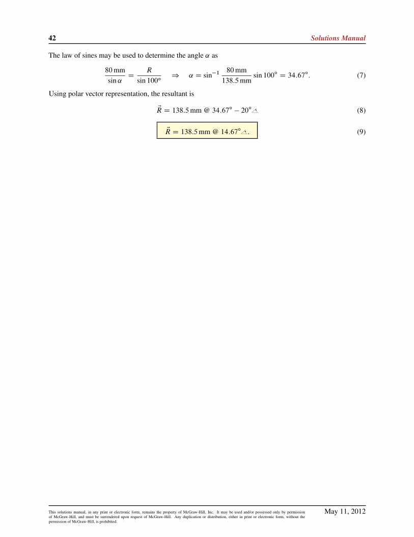
The law of sines may be used to determine the angle ˛ as
80mmsin˛
DR
sin 100ı) ˛ D sin�1 80mm
138:5mmsin 100ı D 34:67ı: (7)
Using polar vector representation, the resultant is
ER D 138:5mm @ 34:67ı � 20ı (8)
ER D 138:5mm @ 14:67ı : (9)
May 11, 2012This solutions manual, in any print or electronic form, remains the property of McGraw-Hill, Inc. It may be used and/or possessed only by permissionof McGraw-Hill, and must be surrendered upon request of McGraw-Hill. Any duplication or distribution, either in print or electronic form, without thepermission of McGraw-Hill, is prohibited.

Statics 2e 43
Problem 2.5
Add the two vectors shown to form a resultant vector ER, and report your resultusing polar vector representation.
Solution
30°
R
30°3 ft
4 ft
Part (a) The vector polygon shown at the right corresponds to the addition of the twoposition vectors to obtain the resultant position vector ER. The law of cosines may be usedto determine R as
R D
q.3 ft/2 C .4 ft/2 � 2.3 ft/.4 ft/ cos 120ı
D 6:083 ft: (1)
The law of sines may be used to determine the angle ˛ as
4 ftsin˛
DR
sin 120ı) ˛ D sin�1 4 ft
6:083 ftsin 120ı D 34:72ı: (2)
Using polar vector representation, the resultant is
ER D 6:083 ft @ �.180ı � 30ı � ˛/ (3)
ER D 6:083 ft @ �115:3ı : (4)
If desired, this resultant may be stated using a positive angle, where 360ı � 115:3ı D 244:7ı, as
ER D 6:083 ft @ 244:7ı : (5)
Part (b) The vector polygon shown at the right corresponds to the addition ofthe two force vectors to obtain the resultant force vector ER. Given the 10ı and20ı angles provided in the problem statement, we determine the angle oppositeR to be 10ı C 90ı � 20ı D 80ı. The law of cosines may be used to determineR as
R D
q.300 lb/2 C .400 lb/2 � 2.300 lb/.400 lb/ cos 80ı
D 456:4 lb: (6)
The law of sines may be used to determine the angle ˛ as
300 lbsin˛
DR
sin 80ı) ˛ D sin�1 300 lb
456:4 lbsin 80ı D 40:34ı: (7)
Using polar vector representation, the resultant is
ER D 456:4 lb @ 180ı C 20ı � ˛ (8)
ER D 456:4 lb @ 159:7ı : (9)
May 11, 2012This solutions manual, in any print or electronic form, remains the property of McGraw-Hill, Inc. It may be used and/or possessed only by permissionof McGraw-Hill, and must be surrendered upon request of McGraw-Hill. Any duplication or distribution, either in print or electronic form, without thepermission of McGraw-Hill, is prohibited.

44 Solutions Manual
Problem 2.6
Add the two vectors shown to form a resultant vector ER, and report your resultusing polar vector representation.
Solution
R
200 lb
139 lbPart (a) The vector polygon shown at the right corresponds to the addition of thetwo force vectors to obtain a resultant force vector ER. Since the two forces beingadded are perpendicular, basic trigonometry may be used to obtain R and ˛ as
R D
q.139 lb/2 C .200 lb/2 D 243:6 lb; (1)
˛ D tan�1 200 lb139 lb
D 55:20ı: (2)
Using polar vector representation, the resultant is
ER D 243:6 lb @ �.90ı � 55:20ı/ (3)
ER D 243:6 lb @ �34:80ı : (4)
If desired, this resultant may be stated using a positive angle, where 360ı � 34:80ı D 325:2ı, as
ER D 243:6 lb @ 325:2ı : (5)
Part (b) The vector polygon shown at the right corresponds to the addition of the twoposition vectors to obtain a resultant position vector ER. The law of cosines may be used todetermine R as
R D
q.6 in./2 C .8 in./2 � 2.6 in./.8 in./ cos 80ı
D 9:129 in. (6)
The law of sines may be used to determine the angle ˛ as
8 in.sin˛
DR
sin 80ı) ˛ D sin�1 8 in.
9:129 in.sin 80ı D 59:66ı: (7)
Using polar vector representation, the resultant is
ER D 9:129 in. @ 180ı � 20ı � ˛ (8)
ER D 9:129 in. @ 100:3ı : (9)
May 11, 2012This solutions manual, in any print or electronic form, remains the property of McGraw-Hill, Inc. It may be used and/or possessed only by permissionof McGraw-Hill, and must be surrendered upon request of McGraw-Hill. Any duplication or distribution, either in print or electronic form, without thepermission of McGraw-Hill, is prohibited.

Statics 2e 45
Problem 2.7
Add the two vectors shown to form a resultant vector ER, and report your resultusing polar vector representation.
Solution
35 kN
18 kN
R
β
Part (a) The vector polygon shown at the right corresponds to the addition of the twoforce vectors to obtain a resultant force vector ER. Using this vector polygon, we determineR and ˇ as
R D
q.35 kN/2 C .18 kN/2 D 39:36 kN; ˇ D tan�1
35 kN18 kN
!D 62:78ı: (1)
The direction for ER measured from the right-hand horizontal direction is 180ı� 62:78ı D 117:2ı. Therefore,the polar vector representation for ER is
ER D 39:4 kN @ 117ı : (2)
45◦
45◦ 60◦αβ
R
1.89 ft1.23 ft
Part (b) The vector polygon shown at the right corresponds to the addition of thetwo position vectors to obtain a resultant position vector ER. We observe from thisvector polygon that ˛ D 180ı � 60ı � 45ı D 75ı. Using the law of cosines
R D
q.1:23 ft/2 C .1:89 ft/2 � 2.1:23 ft/.1:89 ft/ cos 75ı D 1:970 ft: (3)
Next, use the law of sines to find ˇ, such that
1:89 ftsinˇ
DR
sin˛) ˇ D sin�1
�1:89 ft1:970 ft
sin 75ı�D 67:91ı: (4)
The direction of ER measured from the right-hand horizontal direction is 67:91ı � 45ı D 22:91ı. Therefore,the polar vector representation of ER is
ER D 1:97 ft @ 22:9ı : (5)
May 11, 2012This solutions manual, in any print or electronic form, remains the property of McGraw-Hill, Inc. It may be used and/or possessed only by permissionof McGraw-Hill, and must be surrendered upon request of McGraw-Hill. Any duplication or distribution, either in print or electronic form, without thepermission of McGraw-Hill, is prohibited.

46 Solutions Manual
Problem 2.8
Let EA D 2m @ 0ı and EB D 6m @ 90ı . Sketch the vector polygons and evaluate ER for the following,reporting your answer using polar vector representation.
(a) ER D EAC EB ,
(b) ER D 2 EA � EB ,
(c) ER D j EAj EB C j EBj EA,
(d) ER DEA
j EAjCEB
j EBj.
Solution
B
A
R
β
Part (a) The vector polygon is shown to the right. The magnitude R of vector ER is given by
R DpA2 C B2 D
q.2m/2 C .6m/2 D 6:325m: (1)
Referring to the figure again, we find ˇ in the following manner:
R cosˇ D A ) ˇ D cos�1
2m
6:325m
!D 71:57ı: (2)
The polar vector representation of ER is
ER D 6:32m @ 71:6ı : (3)
−B
2A
R
βPart (b) Referring to the vector polygon shown at the right, we determine thevalues for R and ˇ as
R D
q.2 � 2m/2 C .6m/2 D 7:211m; ˇ D sin�1
6m
7:211m
!D 56:31ı: (4)
The polar vector representation of ER is
ER D 7:21m @ �56:3ı : (5)
12 m2
θ
Rβ
12 m2
Part (c) Each vector j EAj EB and j EBj EA has a magnitude of 12m2; since they areperpendicular to one another, it follows that ˇ D 45ı and � D 45ı. The magnitudeof R is given by
R D
q.12m2/2 C .12m2/2 D 16:97m2: (6)
The polar vector representation of ER is
ER D 17:0m2 @ 45:0ı : (7)
May 11, 2012This solutions manual, in any print or electronic form, remains the property of McGraw-Hill, Inc. It may be used and/or possessed only by permissionof McGraw-Hill, and must be surrendered upon request of McGraw-Hill. Any duplication or distribution, either in print or electronic form, without thepermission of McGraw-Hill, is prohibited.

Statics 2e 47
1
1R
β
Part (d) Each vector EA=j EAj and EB=j EBj has a magnitude of one; since they are perpendicularto one another, it follows that ˇ D 45ı. The magnitude and polar vector representation of R are
R D
q.1/2 C .1/2 D 1:414: (8)
ER D 1:41 @ 45:0ı : (9)
May 11, 2012This solutions manual, in any print or electronic form, remains the property of McGraw-Hill, Inc. It may be used and/or possessed only by permissionof McGraw-Hill, and must be surrendered upon request of McGraw-Hill. Any duplication or distribution, either in print or electronic form, without thepermission of McGraw-Hill, is prohibited.
48 Solutions Manual
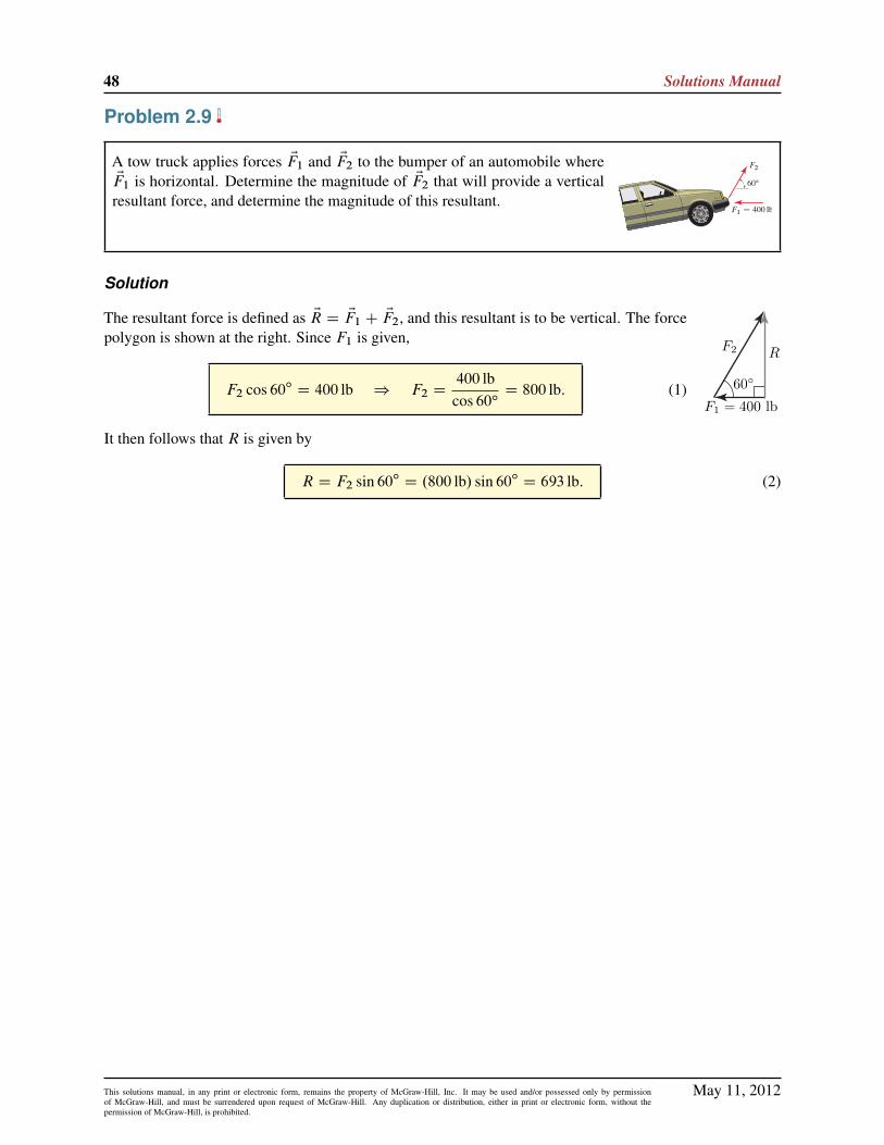
Problem 2.9
A tow truck applies forces EF1 and EF2 to the bumper of an automobile whereEF1 is horizontal. Determine the magnitude of EF2 that will provide a vertical
resultant force, and determine the magnitude of this resultant.
Solution
F1 = 400 lb60◦
RF2
The resultant force is defined as ER D EF1 C EF2, and this resultant is to be vertical. The forcepolygon is shown at the right. Since F1 is given,
F2 cos 60ı D 400 lb ) F2 D400 lb
cos 60ıD 800 lb: (1)
It then follows that R is given by
R D F2 sin 60ı D .800 lb/ sin 60ı D 693 lb: (2)
May 11, 2012This solutions manual, in any print or electronic form, remains the property of McGraw-Hill, Inc. It may be used and/or possessed only by permissionof McGraw-Hill, and must be surrendered upon request of McGraw-Hill. Any duplication or distribution, either in print or electronic form, without thepermission of McGraw-Hill, is prohibited.

Statics 2e 49
Problem 2.10
One of the support brackets for the lawn mowing deck of a garden tractor isshown where EF1 is horizontal. Determine the magnitude of EF2 so that theresultant of these two forces is vertical, and determine the magnitude of thisresultant.
Solution
F2
R15°1000 N
The vector polygon corresponding to the addition of EF1 and EF2 is shown at the right,where, as given in the problem statement, ER is vertical. Thus,
F2 cos 15ı D 1000N ) F2 D 1035N (1)
R D F2 sin 15ı D .1035N/ sin 15ı D 267:9N (2)
May 11, 2012This solutions manual, in any print or electronic form, remains the property of McGraw-Hill, Inc. It may be used and/or possessed only by permissionof McGraw-Hill, and must be surrendered upon request of McGraw-Hill. Any duplication or distribution, either in print or electronic form, without thepermission of McGraw-Hill, is prohibited.

50 Solutions Manual
Problem 2.11
A buoy at point B is located 3 km east and 4 km north of boat A. Boat C islocated 4 km from the buoy and 8 km from boat A. Determine the possibleposition vectors that give the position from boat A to boat C , ErAC . State youranswers using polar vector representation.
Solution
The locations of boat A and buoy B are shown. To determine the possible locations of boat C , we drawa circle with 8 km radius with center at A, and we draw a circle with 6 km radius with center at B; theintersections of these two circles are possible locations of boat C .
Possible locationsof boat C
53.13°
8 km
5 km
4 km
B
A
tan�1 4 km3 km
D 53:13ı;
rAB D
q.3 km/2 C .4 km/2
D 5 km:
The two vector polygons corresponding to
ErAC D ErAB C ErBC (1)
are shown below
53.13°
8 km
4 km
5 km
A
B
C
8 km
BC
A
4 km
5 km
53.13°
For the vector polygon shown at the left, the law of cosines provides
.4 km/2 D .5 km/2 C .8 km/2 � 2.5 km/.8 km/ cos˛; (2)
˛ D cos�1 .4 km/2 � .5 km/2 � .8 km/2
�2.5 km/.8 km/D 24:15ı: (3)
Hence, one of the possible position vectors from boat A to boat C is
ErAC D 8 km @ ˛ C 53:13ı
D 8 km @ 77:28ı(4)
(5)
May 11, 2012This solutions manual, in any print or electronic form, remains the property of McGraw-Hill, Inc. It may be used and/or possessed only by permissionof McGraw-Hill, and must be surrendered upon request of McGraw-Hill. Any duplication or distribution, either in print or electronic form, without thepermission of McGraw-Hill, is prohibited.

Statics 2e 51
For the vector polygon shown at the right, the law of cosines provides
.4 km/2 D .5 km/2 C .8 km/2 � 2.5 km/.8 km/ cosˇ; (6)
ˇ D cos�1 .4 km/2 � .5 km/2 � .8 km/2
�2.5 km/.8 km/D 24:15ı: (7)
Hence, the other possible position vector from boat A to boat C is
ErAC D 8 km @ 53:13ı � ˇ
D 8 km @ 28:98ı :
(8)
(9)
Remark: Equations (2) and (6) are identical, and hence ˛ D ˇ D 24:15ı. In fact, Eq. (2) has multiplesolutions, two of which are ˛ D ˙24:15ı. Using this result, we could have arrived with both answers to thisproblem, namely Eqs. (5) and (9).
May 11, 2012This solutions manual, in any print or electronic form, remains the property of McGraw-Hill, Inc. It may be used and/or possessed only by permissionof McGraw-Hill, and must be surrendered upon request of McGraw-Hill. Any duplication or distribution, either in print or electronic form, without thepermission of McGraw-Hill, is prohibited.

52 Solutions Manual
Problem 2.12
Arm OA of a robot is positioned as shown. Determine the value for angle ˛ ofarm AB so that the distance from point O to the actuator at B is 650mm.
Solution
The two vector polygons shown below illustrate the addition ErOB D ErOA C ErAB . These vector polygonsshow the two possible positions of arm AB such that the distance between points O and B is 650mm.
First vector polygon: Applying the law of cosines, we obtain
650mm Dq.300mm/2 C .400mm/2 � 2.300mm/.400mm/ cosˇ: (1)
By squaring both sides and solving for ˇ, we find that
ˇ D cos�1
".650mm/2 � .300mm/2 � .400mm/2
�2.300mm/.400mm/
#(2)
D cos�1.�23=32/ (3)
D 136:0ı (4)
To determine ˛, observe that
180ı D ˇ � ˛ C 60ı ) ˛ D ˇ C 60ı � 180ı D 16:0ı: (5)
Second vector polygon: Using the second vector polygon, Eq. (1) is still valid, which again providesˇ D 136:0ı. Thus,
180ı D ˛ C ˇ � 60ı ) ˛ D 180ı � ˇ C 60ı� D 104ı: (6)
May 11, 2012This solutions manual, in any print or electronic form, remains the property of McGraw-Hill, Inc. It may be used and/or possessed only by permissionof McGraw-Hill, and must be surrendered upon request of McGraw-Hill. Any duplication or distribution, either in print or electronic form, without thepermission of McGraw-Hill, is prohibited.

Statics 2e 53
Problem 2.13
Add the three vectors shown to form a resultant vector ER, and report your resultusing polar vector representation.
Solution
R
80 lb
60 lb
40 lb
P
45◦
α
α
γ
Part (a) The vector polygon shown at the right corresponds to the addition of thethree force vectors to obtain a resultant force vector ER. Although our goal is todetermine ER, we will begin by determining EP . The magnitude of EP is given by
P D
q.60 lb/2 C .80 lb/2 D 100 lb: (1)
The angle ˛ is found by
tan˛ D60 lb80 lb
) ˛ D tan�1
60 lb80 lb
!D 36:87ı: (2)
Next, use the law of cosines to find R
R D
qP 2 C .40 lb/2 � 2P.40 lb/ cos.45ı C ˛/ D 102:3 lb: (3)
Use the law of sines to find
R
sin.45ı C ˛/D40 lbsin
) D sin�1
40 lb sinˇ
R
!D 22:77ı: (4)
In polar vector representation, the direction of ER measured from the right-hand horizontal direction is givenby the sum of ˛ and , such that
ER D 102 lb @ 59:6ı : (5)
Part (b) The vector polygon shown at the right corresponds to the addition of the three position vectors toobtain a resultant position vector ER. By inspection, the angle of EP is 45ı, while P is given given by
P D
q.8mm/2 C .8mm/2 D 11:31mm: (6)
β
30◦
30◦R
15 mm
45◦
P
8 mm8 mm
The law of cosines is used to find R
R D
qP 2 C .15mm/2 � 2P.15mm/ cos.45ı C 30ı/ D 16:28mm: (7)
The law of sines is used to determine the angle ˇ as
P
sinˇD
R
sin.45ı C 30ı/) ˇ D sin�1
"11:31mm sin.75ı/
16:28mm
#D 42:15ı: (8)
The direction of ER measured from the right-hand horizontal direction is given by �ˇ � 30ı D �72:15ı, andthe polar vector representation of ER is
ER D 16:3mm @ �72:2ı : (9)
May 11, 2012This solutions manual, in any print or electronic form, remains the property of McGraw-Hill, Inc. It may be used and/or possessed only by permissionof McGraw-Hill, and must be surrendered upon request of McGraw-Hill. Any duplication or distribution, either in print or electronic form, without thepermission of McGraw-Hill, is prohibited.
54 Solutions Manual
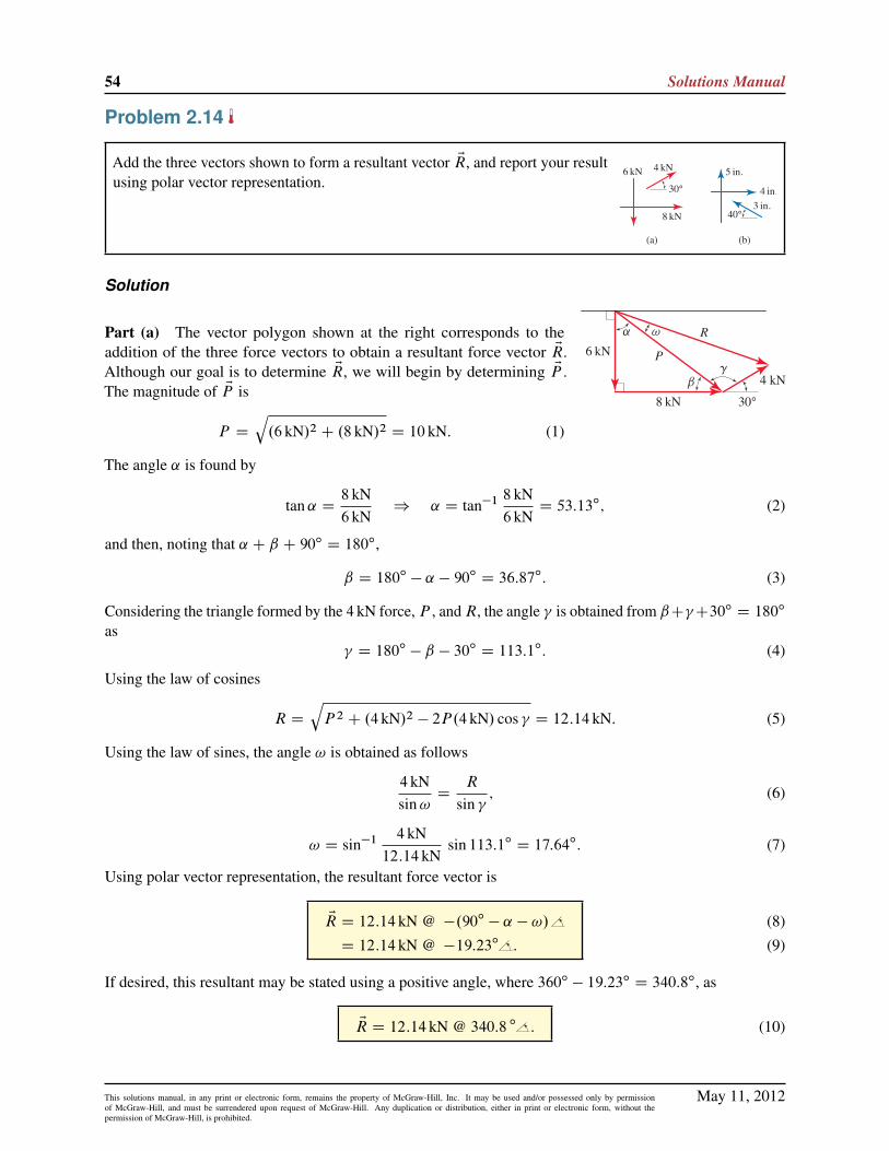
Problem 2.14
Add the three vectors shown to form a resultant vector ER, and report your resultusing polar vector representation.
Solution
Part (a) The vector polygon shown at the right corresponds to theaddition of the three force vectors to obtain a resultant force vector ER.Although our goal is to determine ER, we will begin by determining EP .The magnitude of EP is
P D
q.6 kN/2 C .8 kN/2 D 10 kN: (1)
The angle ˛ is found by
tan˛ D8 kN6 kN
) ˛ D tan�1 8 kN6 kN
D 53:13ı; (2)
and then, noting that ˛ C ˇ C 90ı D 180ı,
ˇ D 180ı � ˛ � 90ı D 36:87ı: (3)
Considering the triangle formed by the 4 kN force, P , andR, the angle is obtained from ˇC C30ı D 180ı
as D 180ı � ˇ � 30ı D 113:1ı: (4)
Using the law of cosines
R D
qP 2 C .4 kN/2 � 2P.4 kN/ cos D 12:14 kN: (5)
Using the law of sines, the angle ! is obtained as follows
4 kNsin!
DR
sin ; (6)
! D sin�1 4 kN12:14 kN
sin 113:1ı D 17:64ı: (7)
Using polar vector representation, the resultant force vector is
ER D 12:14 kN @ �.90ı � ˛ � !/
D 12:14 kN @ �19:23ı :
(8)
(9)
If desired, this resultant may be stated using a positive angle, where 360ı � 19:23ı D 340:8ı, as
ER D 12:14 kN @ 340:8 ı : (10)
May 11, 2012This solutions manual, in any print or electronic form, remains the property of McGraw-Hill, Inc. It may be used and/or possessed only by permissionof McGraw-Hill, and must be surrendered upon request of McGraw-Hill. Any duplication or distribution, either in print or electronic form, without thepermission of McGraw-Hill, is prohibited.

Statics 2e 55
R
P
a
40°
5 in.
3 in.
4 in.
Part (b) The vector polygon shown at the right corresponds to the addition of thethree position vectors to obtain a resultant position vector ER. Although our goal isto determine ER, we will begin by determining EP . The magnitude of EP is
P D
q.4 in./2 C .5 in./2 D 6:403 in. (11)
The angle ˛ is found by
tan˛ D5 in.4 in.
) ˛ D tan�1 5 in.4 in.D 51:34ı: (12)
Considering the triangle formed by the 3 in. position vector, P , and R, the law ofcosines may be used to obtain
R D
q.3 in./2 C P 2 � 2.3 in./P cos.40ı C ˛/ D 7:134 in.; (13)
and the law of sines may be used to determine the angle ˇ as
3 in.sinˇ
DR
sin.40ı C ˛/) ˇ D sin�1 3 in.
7:134 in.sin.40ı C 51:34ı/ D 24:86ı: (14)
Using polar vector representation, the resultant position vector is
ER D 7:134 in. @ ˛ C ˇ
D 7:134 in. @ 76:20ı :
(15)
(16)
May 11, 2012This solutions manual, in any print or electronic form, remains the property of McGraw-Hill, Inc. It may be used and/or possessed only by permissionof McGraw-Hill, and must be surrendered upon request of McGraw-Hill. Any duplication or distribution, either in print or electronic form, without thepermission of McGraw-Hill, is prohibited.

56 Solutions Manual
Problem 2.15
Add the three vectors shown to form a resultant vector ER, and report your resultusing polar vector representation.
Solution
Part (a) The vector polygon shown at the right corresponds to the addition of the threeforce vectors to obtain a resultant force vector ER. Although our goal is to determineER, we will begin by determining EP . The magnitude of EP is
P D
q.100 lb/2 C .200 lb/2 D 223:6 lb: (1)
The angle ˛ is found by
tan˛ D100 lb200 lb
) ˛ D tan�1 100 lb200 lb
D 26:57ı; (2)
and then, noting that ˛ C ˇ C 90ı D 180ı,
ˇ D 180ı � ˛ � 90ı D 63:43ı: (3)
Considering the triangle formed by the 150 lb force, P , andR, the angle is obtained from C˛ D 90ıC30ı
as D 90ı C 30ı � ˛ D 93:43ı: (4)
Using the law of cosines
R D
q.150 lb/2 C P 2 � 2.150 lb/P cos D 276:6 lb: (5)
Using the law of sines, the angle ! is obtained from
150 lbsin!
DR
sin ) ! D sin�1 150 lb
276:6 lbsin 93:43ı D 32:77ı: (6)
Using polar vector representation, the resultant force is
ER D 276:6 lb @ 180ı � ˇ � !
D 276:6 lb @ 83:79ı :
(7)
(8)
May 11, 2012This solutions manual, in any print or electronic form, remains the property of McGraw-Hill, Inc. It may be used and/or possessed only by permissionof McGraw-Hill, and must be surrendered upon request of McGraw-Hill. Any duplication or distribution, either in print or electronic form, without thepermission of McGraw-Hill, is prohibited.

Statics 2e 57
Part (b) The vector polygon shown at the right corresponds to the ad-dition of the three position vectors to obtain a resultant position vector ER.Although our goal is to determine ER, we will begin by determining EP . Themagnitude of EP is
P D
q.2m/2 C .3m/2 D 3:606m: (9)
The angle ˛ is found by
tan˛ D3m2m
) ˛ D tan�1 3m2mD 56:31ı; (10)
and then, noting that ˛ C ˇ C 90ı D 180ı,
ˇ D 180ı � ˛ � 90ı D 33:69ı: (11)
Considering the triangle formed by the 4 m position vector, P , and R, the angle is obtained from˛ C C 30ı D 180ı as
D 180ı � ˛ � 30ı D 93:69ı: (12)
Using the law of cosines
R D
q.4m/2 C P 2 � 2.4m/P cos D 5:555m: (13)
Using the law of sines,
4msin!
DR
sin ) ! D sin�1 4m
5:555msin 93:69ı D 45:94ı: (14)
Using polar vector representation, the resultant position vector is
ER D 5:555m @ �.90ı � ˇ � !/
D 5:555m @ �10:37ı :
(15)
(16)
If desired, the resultant may be stated using a positive angle, where 360ı � 10:37ı D 349:6ı as
ER D 5:555m @ 349:6ı : (17)
May 11, 2012This solutions manual, in any print or electronic form, remains the property of McGraw-Hill, Inc. It may be used and/or possessed only by permissionof McGraw-Hill, and must be surrendered upon request of McGraw-Hill. Any duplication or distribution, either in print or electronic form, without thepermission of McGraw-Hill, is prohibited.
58 Solutions Manual
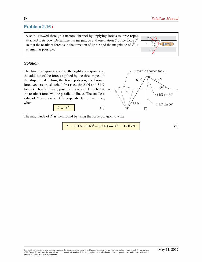
Problem 2.16
A ship is towed through a narrow channel by applying forces to three ropesattached to its bow. Determine the magnitude and orientation � of the force EFso that the resultant force is in the direction of line a and the magnitude of EF isas small as possible.
Solution
2 kN
a
3 kN sin 60◦
Possible choices for F .
2 kN sin 30◦
60◦
30◦a
3 kN
The force polygon shown at the right corresponds tothe addition of the forces applied by the three ropes tothe ship. In sketching the force polygon, the knownforce vectors are sketched first (i.e., the 2 kN and 3 kNforces). There are many possible choices of EF such thatthe resultant force will be parallel to line a. The smallestvalue of F occurs when EF is perpendicular to line a; i.e.,when
� D 90ı: (1)
The magnitude of EF is then found by using the force polygon to write
F D .3 kN/ sin 60ı � .2 kN/ sin 30ı D 1:60 kN: (2)
May 11, 2012This solutions manual, in any print or electronic form, remains the property of McGraw-Hill, Inc. It may be used and/or possessed only by permissionof McGraw-Hill, and must be surrendered upon request of McGraw-Hill. Any duplication or distribution, either in print or electronic form, without thepermission of McGraw-Hill, is prohibited.

Statics 2e 59
Problem 2.17
A surveyor needs to plant a marker directly northeast from where she is standing. Because of obstacles,she walks a route in the horizontal plane consisting of 200m east, followed by 400m north, followed by300m northeast. From this position, she would like to take the shortest-distance route back to the line thatis directly northeast of her starting position. What direction should she travel and how far, and what willbe her final distance from her starting point?
Solution
200m
N-EE
N
400m
300m
45◦45◦
200m sin 45◦200m cos 45◦ 400m sin 45◦
d
400m cos 45◦
The vector polygon shown at the right corresponds to the additionof the four position vectors corresponding to the path walked bythe surveyor. The first three position vectors take the surveyorto the point at which she begins to travel back to the line thatis directly north-east of her starting position (this direction isshown as a dashed line in the vector polygon). The path shetakes to reach this line has distance d , and several possibilitiesare shown. By examining the vector polygon, the smallest valueof d results when she travels directly south-east, in which cased is given by
d D .400m/ sin 45ı � .200m/ sin 45ı D 141m: (1)
To summarize,
The surveyor should walk 141m in the S-E direction. (2)
The distance R from her starting point to her final position is given by
R D .200m/ cos 45ı C .400m/ cos 45ı C 300m D 724m: (3)
May 11, 2012This solutions manual, in any print or electronic form, remains the property of McGraw-Hill, Inc. It may be used and/or possessed only by permissionof McGraw-Hill, and must be surrendered upon request of McGraw-Hill. Any duplication or distribution, either in print or electronic form, without thepermission of McGraw-Hill, is prohibited.

60 Solutions Manual
Problem 2.18
A utility pole supports a bundle of wires that apply the 400 and 650N forcesshown, and a guy wire applies the force EP .
(a) If P D 0, determine the resultant force applied by the wires to the poleand report your result using polar vector representation.
(b) Repeat Part (a) if P D 500N and ˛ D 60ı.
(c) With ˛ D 60ı, what value of P will produce a resultant force that isvertical?
(d) If the resultant force is to be vertical and P is to be as small as possible,determine the value ˛ should have and the corresponding value of P .
Solution
Part (a) Either of the force polygons shown at the right may be used to determinethe resultant force Q. Regardless of which force polygon is used, the law of cosinesprovides
Q D
q.400N/2 C .650N/2 � 2.400N/.650N/ cos 30ı D 363:5N (1)
Using the first force polygon shown, the law of sines is used to determine the angle �1
as400Nsin �1
DQ
sin 30ı) �1 D sin�1
.400N/ sin 30ı
363:5N
!D 33:38ı: (2)
The orientation of EQ to be used for its polar vector representation is 180ı � �1 D 180ı � 33:38ı D 146:6ı,
and hence the vector representation of EQ is
EQ D 364N @ 147ı : (3)
Alternatively, the second force polygon could be used. As discussed above, Eq. (1) still applies, andQ D 363:3N. Because angle �2 appears to be obtuse, we will avoid using the law of sines to determine itsvalue (see the discussion in the text regarding the pitfall when using the law of sines to determine an obtuseangle). Using the law of sines to determine angle �3 provides
400Nsin �3
DQ
sin 30ı) �3 D sin�1
.400N/ sin 30ı
363:5N
!D 33:38ı: (4)
Once �3 is known, angle �2 is easily found as
�2 D 180ı� �3 � 30
ıD 180ı � 33:38ı � 30ı D 116:6ı: (5)
The orientation of EQ to be used for its polar vector representation is 30ı C �2 D 30ı C 116:6ı D 146:6ı,
and hence the vector representation of EQ is
EQ D 364N @ 147ı : (6)
As expected, the same result for EQ is obtained regardless of which force polygon was used.
May 11, 2012This solutions manual, in any print or electronic form, remains the property of McGraw-Hill, Inc. It may be used and/or possessed only by permissionof McGraw-Hill, and must be surrendered upon request of McGraw-Hill. Any duplication or distribution, either in print or electronic form, without thepermission of McGraw-Hill, is prohibited.

Statics 2e 61
Part (b) Our strategy will be to add the force vector EP to the result for EQobtained in Part (a). Thus, the force polygon is shown at the right, where Q fromEq. (1) and �1 from Eq. (2) are used, such that
�4 D 60ı� �1 D 60
ı� 33:38ı D 26:62ı: (7)
The law of cosines may be used to find R:
R D
q.500N/2 C .363:5N/2 � 2.500N/.363:3N/ cos �4 D 239:1N: (8)
Since �5 is obtuse, we will avoid using the law of sines to determine it, and instead will use the law of sinesto determine �6, as follows
R
sin �4D363:5Nsin �6
) �6 D sin�1
.363:5N/ sin �4
R
!D 42:95ı: (9)
The angle �5 is given by�5 D 180
ı� �4 � �6 D 110:4
ı: (10)
The orientation of ER relative to the right-hand horizontal direction is the sum of the orientation of EQ obtainedin Part (a), namely 146:6ı, plus �5. Thus
ER D 239N @ 257ı : (11)
Part (c) The force polygon is shown at the right, where angle �4 D 26:62ı was
determined in Eq. (7). For the resultant force ER to be vertical, �7 D 90ı C �1 D
90ı C 33:38ı D 123:4ı Thus
�8 D 180ı� �4 � �7 D 30
ı: (12)
The law of sines is used to determine P as
363:5Nsin �8
DP
sin �7(13)
) P D .363:5N/sin 123:4ı
sin 30ıD 607N: (14)
Part (d) Using the results for EQ from Part (a), and if the resultant force is to be vertical,then the force polygon is as shown at the right; three possible choices (among manypossibilities) for P along with the corresponding resultant force are shown. The smallestvalue of P occurs when EP is perpendicular to ER, hence
˛ D 0ı: (15)
For this value of ˛,
P D .363:5N/ cos 33:38ı D 304N: (16)
May 11, 2012This solutions manual, in any print or electronic form, remains the property of McGraw-Hill, Inc. It may be used and/or possessed only by permissionof McGraw-Hill, and must be surrendered upon request of McGraw-Hill. Any duplication or distribution, either in print or electronic form, without thepermission of McGraw-Hill, is prohibited.

62 Solutions Manual
Problem 2.19
The end of a cantilever I beam supports forces from three cables.(a) If P D 0, determine the resultant force applied by the two cables to the
I beam and report your result using polar vector representation.
(b) Repeat Part (a) if P D 1:5 kip and ˛ D 30ı.
(c) With ˛ D 30ı, what value of P will produce a resultant force that ishorizontal?
(d) If the resultant force is to be horizontal and P is to be as small as possible,determine the value ˛ should have and the corresponding value of P .
Solution
Part (a) The force polygon shown at the right may be used to determine the resultantforce Q, Noting that the angle opposite Q is 180ı � 60ı D 120ı; the law of cosines maybe used to obtain
Q D
q.1 kip/2 C .2 kip/2 � 2.1 kip/.2 kip/ cos 120ı D 2:646 kip: (1)
Using the law of sines, the angle �1, is obtained as follows
1 kipsin �1
DQ
sin 120ı) �1 D sin�1
�1 kip
2.646 kipsin 120ı
�D 19:11ı: (2)
Using polar vector representation, the resultant force is
EQ D 2:646 kip @ �.90ı � �1/
D 2:646 kip @ �70.89ı :
(3)
(4)
If desired, the resultant force may be stated using a positive angle, where 360ı � 70:89ı D 289:1ı; as
EQ D 2:646 kip @ 289.1ı : (5)
Part (b) Our strategy will be to add the force vector EP to the result for EQobtained in Part (a). Thus, the force polygon is shown at the right whereQ from Eq. (1) and �1 from Eq. (2) are used, and �2 is obtained from�1 C �2 C 90
ı D 180ı which provides
�2 D 180ı� �1 � 90
ıD 70:89ı: (6)
The angle opposite force R is obtained by using �2 C �3 C 30ı D 180ı; which provides
�3 D 180ı� �2 � 30
ıD 79:11ı: (7)
May 11, 2012This solutions manual, in any print or electronic form, remains the property of McGraw-Hill, Inc. It may be used and/or possessed only by permissionof McGraw-Hill, and must be surrendered upon request of McGraw-Hill. Any duplication or distribution, either in print or electronic form, without thepermission of McGraw-Hill, is prohibited.

Statics 2e 63
Using the law of cosines, the resultant force is
R Dp.1:5 kip/2 C .2:646 kip/2 � 2.1:5 kip/.2:646 kip/ cos �3
D 2:784 kip:(8)
Using the law of sines, angle �4 may be determined
1:5 kipsin �4
DR
sin �3) �4 D sin�1
�1:5 kip2:784 kip
sin 79:11ı�D 31:95ı: (9)
Using polar vector representation, the resultant force is
ER D 2:784 kip @ �.90ı � �1 � �4/
D 2:784 kip @ �38:95ı :
(10)
(11)
If desired, the resultant may be stated using a positive angle, where 360ı � 38:95ı D 321:1ı; as
ER D 2:784 kip @ 321.1ı : (12)
Part (c) The force polygon is shown below
For the resultant force R to be horizontal, using �1 C �5 D 90ı; we obtain
�5 D 90ı� �1 D 70:89
ı; (13)
and noting that �5 C �6 C 30ı D 180ı; we obtain
�6 D 180ı� �5 � 30
ıD 79:11ı: (14)
Using the law of sines, with Q D 2:646 kip from Part (a),R
sin �6D
Q
sin 30ı; (15)
R D 2:646 kipsin 79:11ı
sin 30ıD 5:196 kip: (16)
Part (d) Using the results for Q from Part (a), and if the resultant force isto be horizontal, then the force polygon is shown at the right; three possiblechoices (among many possibilities) for P along with the correspondingresultant force R are shown. The smallest value of P occurs when EP isperpendicular to ER, hence
˛ D 90ı; (17)
andP D .2:646 kip/ cos 19:11ı D 2:500 kip: (18)
May 11, 2012This solutions manual, in any print or electronic form, remains the property of McGraw-Hill, Inc. It may be used and/or possessed only by permissionof McGraw-Hill, and must be surrendered upon request of McGraw-Hill. Any duplication or distribution, either in print or electronic form, without thepermission of McGraw-Hill, is prohibited.

64 Solutions Manual
Problem 2.20
Determine the smallest force F1 such that the resultant of the three forces F1, F2,and F3 is vertical, and the angle ˛ at which F1 should be applied.
Solution
The force polygon, including various choices for EF1, is shown at the right. Thesmallest value of F1 occurs when the vector EF1 is horizontal, hence
˛ D 0ı; (1)
and the force is
F1 D .30 kN/ sin 40ı D 19:28 kN: (2)
May 11, 2012This solutions manual, in any print or electronic form, remains the property of McGraw-Hill, Inc. It may be used and/or possessed only by permissionof McGraw-Hill, and must be surrendered upon request of McGraw-Hill. Any duplication or distribution, either in print or electronic form, without thepermission of McGraw-Hill, is prohibited.

Statics 2e 65
Problem 2.21
Determine the smallest force F1 such that the resultant of the three forces F1,F2, and F3 is vertical, and the angle ˛ at which F1 should be applied.
Solution
200 lb
100 lb
Possible choices for F1.
30◦
45◦
The force polygon, including various choices for EF1, is shown to the right.The smallest value of F1 occurs when the vector EF1 is horizontal, i.e., when
˛ D 90ı: (1)
The value of F1 is given by
F1 D .200 lb/ cos 45ı � .100 lb/ cos 30ı D 54:8 lb: (2)
May 11, 2012This solutions manual, in any print or electronic form, remains the property of McGraw-Hill, Inc. It may be used and/or possessed only by permissionof McGraw-Hill, and must be surrendered upon request of McGraw-Hill. Any duplication or distribution, either in print or electronic form, without thepermission of McGraw-Hill, is prohibited.
66 Solutions Manual
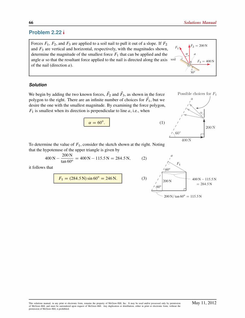
Problem 2.22
Forces F1, F2, and F3 are applied to a soil nail to pull it out of a slope. If F2
and F3 are vertical and horizontal, respectively, with the magnitudes shown,determine the magnitude of the smallest force F1 that can be applied and theangle ˛ so that the resultant force applied to the nail is directed along the axisof the nail (direction a).
Solution
We begin by adding the two known forces, EF2 and EF3, as shown in the forcepolygon to the right. There are an infinite number of choices for EF1, but wedesire the one with the smallest magnitude. By examining the force polygon,F1 is smallest when its direction is perpendicular to line a, i.e., when
˛ D 60ı: (1)
To determine the value of F1, consider the sketch shown at the right. Notingthat the hypotenuse of the upper triangle is given by
400N �200Ntan 60ı
D 400N � 115:5N D 284:5N; (2)
it follows that
F1 D .284:5N/ sin 60ı D 246N: (3)
May 11, 2012This solutions manual, in any print or electronic form, remains the property of McGraw-Hill, Inc. It may be used and/or possessed only by permissionof McGraw-Hill, and must be surrendered upon request of McGraw-Hill. Any duplication or distribution, either in print or electronic form, without thepermission of McGraw-Hill, is prohibited.

Statics 2e 67
Problem 2.23
Determine the magnitudes of vectors Era and Erb in the a and b directions,respectively, such that their sum is the 2 km position vector shown.
Solution
rb
2 km
30◦a
b
ra
Part (a) Because the directions a and b of the two component vectors to be determinedare orthogonal, determination of the magnitudes of the component vectors will bestraightforward. The magnitudes ra and rb of vectors Era and Erb are determined using
ra D .2 km/ sin 30ı D 1:00 km;
rb D .2 km/ cos 30ı D 1:73 km:
(1)
(2)
rb 2 km
30◦ a
b
ra
30◦αPart (b) Because the directions a and b of the two component vectors to
be determined are not orthogonal, determination of the magnitudes of thecomponent vectors will be slightly more work than for Part (a). Observe thatthe angle ˛ D 180ı� 30ı� 120ı D 30ı. The magnitudes ra and rb of vectorsEra and Erb are determined using the law of sines to obtain
2 kmsin 30ı
Drb
sin 120ıD
ra
sin 30ı) ra D �2:00 km; and rb D 3:46 km; (3)
where the negative sign is inserted for ra since it acts in the negative a direction.
May 11, 2012This solutions manual, in any print or electronic form, remains the property of McGraw-Hill, Inc. It may be used and/or possessed only by permissionof McGraw-Hill, and must be surrendered upon request of McGraw-Hill. Any duplication or distribution, either in print or electronic form, without thepermission of McGraw-Hill, is prohibited.

68 Solutions Manual
Problem 2.24
Determine the magnitudes of vectors EFa and EFb in the a and b directions,respectively, such that their sum is the 100 lb force vector shown.
Solution
a
bPart (a) Let Fa and Fb be the components (scalars) of force vectors EFa andEFb , respectively. These components are determined using
Fa D .�100 lb/ sin 15ı D �25:9 lb;
Fb D .100 lb/ cos 15ı D 96:6 lb;
(1)
(2)
where Fa is negative since it acts in the negative a direction. Hence, the magni-tudes of vectors EFa and EFb are
j EFaj D 25:9 lb;
j EFbj D 96:6 lb:
(3)
(4)
Part (b) It is necessary to determine ˛ and ˇ, by noting that
ab
˛ D 180ı � 15ı � 60ı D 105ı; ˇ D 180ı � ˛ � 60ı D 15ı: (5)
The law of sines may then be used to find the components Fa and Fb (scalars)of vectors EFa and EFb as
100 lbsin 60ı
DFb
sin˛D
Fa
sinˇ) Fa D 29:9 lb; Fb D 112 lb: (6)
Hence, the magnitudes of vectors EFa and EFb are
j EFaj D 29:9 lb;
j EFbj D 112 lb:
(7)
(8)
May 11, 2012This solutions manual, in any print or electronic form, remains the property of McGraw-Hill, Inc. It may be used and/or possessed only by permissionof McGraw-Hill, and must be surrendered upon request of McGraw-Hill. Any duplication or distribution, either in print or electronic form, without thepermission of McGraw-Hill, is prohibited.

Statics 2e 69
Problem 2.25
The child’s play structure from Examples 2.2 and 2.3 on pp. 38 and 39 is shownagain. The woman at A applies a force in the a direction and the man at B appliesa force in the b direction, with the goal of producing a resultant force of 250N inthe c direction. Determine the forces the two people must apply, expressing theresults as vectors.
Solution
Let EF denote the 250N force vector acting in the c direction. Our objective is to determine the force vectorsEFa acting in the a direction and EFb acting in the b direction such that
EF D EFa C EFb: (1)
The force polygon corresponding to this addition is shown at the right. Since EFa and EFb areperpendicular, basic trigonometry provides
jFaj D .250N/ cos 65ı D 105:7N (2)
jFbj D .250N/ sin 65ı D 226:6N (3)
Using polar vector representation, the forces are
EFa D 105:7N @ 0ı ; and
EFb D 226:6N @ 90ı :
(4)
(5)
May 11, 2012This solutions manual, in any print or electronic form, remains the property of McGraw-Hill, Inc. It may be used and/or possessed only by permissionof McGraw-Hill, and must be surrendered upon request of McGraw-Hill. Any duplication or distribution, either in print or electronic form, without thepermission of McGraw-Hill, is prohibited.

70 Solutions Manual
Problem 2.26
The child’s play structure from Examples 2.2 and 2.3 on pp. 38 and 39 is shownagain. The woman at A applies a force in the a direction and the man at B applies aforce in the b direction, with the goal of producing a resultant force of 250N in thec direction. Determine the forces the two people must apply, expressing the resultsas vectors.
Solution
Let EF denote the 250 N force vector acting in the c direction. Our objective is to determine the force vectorsEFa acting in the a direction and EFb acting in the b direction such that
EF D EFa C EFb: (1)
Fa
Fb
50°
65°
250 N1
2
3
The force polygon corresponding to this addition is shown at the right. Since EFa and EFb arenot perpendicular, the laws of sines and cosines must be used. The angles �1; �2; and �3 areeasily determined as
�1 D 90ı� 65ı D 25ı; (2)
�2 D 90ı� 50ı D 40ı; (3)
�3 D 180ı� �1 � �2 D 115
ı: (4)
The law of sines provides250Nsin �2
DjFaj
sin �1DjFbj
sin �3; (5)
which yields
jFaj D 250Nsin 25ı
sin 40ıD 164:4N; (6)
jFbj D 250Nsin 115ı
sin 40ıD 352:5N: (7)
Using polar vector representation, the forces are
EFa D 164:4N @ �50ı ; and
EFb D 352:5N @ 90ı :
(8)
(9)
May 11, 2012This solutions manual, in any print or electronic form, remains the property of McGraw-Hill, Inc. It may be used and/or possessed only by permissionof McGraw-Hill, and must be surrendered upon request of McGraw-Hill. Any duplication or distribution, either in print or electronic form, without thepermission of McGraw-Hill, is prohibited.

Statics 2e 71
Problem 2.27
While canoes are normally propelled by paddle, if there is a favorable windfrom the stern, adventurous users will sometimes employ a small sail. If a canoeis sailing north-west and the wind applies a 40 lb force perpendicular to the sailin the direction shown, determine the components of the wind force paralleland perpendicular to the keel of the canoe (direction a).
Solution
F||
F⊥
20◦
40 lb
Let the force perpendicular to the keel be denoted by F? and the force parallel to thekeel be denoted by Fjj. The sketch shown at the right illustrates the addition of thesetwo forces to yield the 40 lb force applied to the sail. Thus,
F? D .40 lb/ sin 20ı D 13:7 lb;
Fjj D .40 lb/ cos 20ı D 37:6 lb:
(1)
(2)
May 11, 2012This solutions manual, in any print or electronic form, remains the property of McGraw-Hill, Inc. It may be used and/or possessed only by permissionof McGraw-Hill, and must be surrendered upon request of McGraw-Hill. Any duplication or distribution, either in print or electronic form, without thepermission of McGraw-Hill, is prohibited.

72 Solutions Manual
Problem 2.28
Repeat Part (b) of Example 2.5, using the optimization methods of calculus.Hint: Redraw the force polygon of Fig. 3 and rewrite Eq. (1) on p. 41 withthe 45ı angle shown there replaced by ˇ, where ˇ is defined in Fig. P2.28.Rearrange this equation to obtain an expression for FOC 0 as a function of ˇ,and then determine the value of ˇ that makes dFOC 0=dˇ D 0. While theapproach described here is straightforward to carry out “by hand,” you mightalso consider using symbolic algebra software such as Mathematica or Maple.
Solution
A relationship for FOC 0 in terms of Fjj and ˇ is needed, and this may be obtainedusing the force polygon shown at the right with the law of sines
400 lbsinˇ
DFOC 0
sin 30ı) FOC 0 D .400 lb/
sin 30ı
sinˇ: (1)
To determine the minimum value of FOC 0 as a function of ˇ, we make FOC 0 stationary by setting itsderivative with respect to ˇ equal to zero; i.e.,
dFOC 0
dˇD 0 D .400 lb/.sin 30ı/
d
dˇ
1
sinˇ
!D .400 lb/.sin 30ı/
cosˇsinˇ
1
sinˇ: (2)
Satisfaction of Eq. (2) requires cosˇ D 0, which gives ˇ D 90ı. From Eq. (1) we obtain
ˇ D 90ı ) FOC 0 D .400 lb/sin 30ı
sin 90ıD 200 lb: (3)
May 11, 2012This solutions manual, in any print or electronic form, remains the property of McGraw-Hill, Inc. It may be used and/or possessed only by permissionof McGraw-Hill, and must be surrendered upon request of McGraw-Hill. Any duplication or distribution, either in print or electronic form, without thepermission of McGraw-Hill, is prohibited.

Statics 2e 73
Problem 2.29
For the following problems, use an xy Cartesian coordinate system where x is horizontal, positive to theright, and y is vertical, positive upward. For problems where the answers require vector expressions, reportthe vectors using Cartesian representations.
Repeat Prob. 2.2 on p. 43.
Solution
55◦
R 183 mm
101 mmx
yPart (a) The 101mm and 183mm position vectors are shown to theright with an xy Cartesian coordinate system, and the sum of these vectorsis given by
ER D�101 O{ C 183.cos 55ı O{ C sin 55ı O|/
�mm
D .206 O{ C 150 O|/ mm:(1)
45◦
R
1.23 kip 1.55 kip
x
yPart (b) The 1:23 kip and 1:55 kip force vectors are shown to the right withan xy Cartesian coordinate system, and the sum of these vectors is given by
ER D��1:55 O| C 1:23.� cos 45ı O{ C sin 45ı O|/
�kip;
D .�0:870 O{ � 0:680 O|/ kip: (2)
May 11, 2012This solutions manual, in any print or electronic form, remains the property of McGraw-Hill, Inc. It may be used and/or possessed only by permissionof McGraw-Hill, and must be surrendered upon request of McGraw-Hill. Any duplication or distribution, either in print or electronic form, without thepermission of McGraw-Hill, is prohibited.

74 Solutions Manual
Problem 2.30
For the following problems, use an xy Cartesian coordinate system where x is horizontal, positive to theright, and y is vertical, positive upward. For problems where the answers require vector expressions, reportthe vectors using Cartesian representations.
Repeat Prob. 2.3 on p. 43.
Solution
y
x
R
18 kN
35 kN
Part (a) The 18 kN and 35 kN force vectors are shown to the right with an xyCartesian coordinate system, and the sum of these vectors is given by
ER D .�18 O{ C 35 O|/ kN: (1)
1.23 ft 1.89 ft
R
60◦
45◦x
yThe 1:23 ft and 1:89 ft position vectors are shown at the right with an xy Cartesiancoordinate system, and the sum of these vectors is given by
ER D 1:23.cos 45ı O{ � sin 45ı O|/ ftC 1:89.cos 60ı O{ C sin 60ı O|/ ft
D .1:81 O{ C 0:767 O|/ ft:
(2)
(3)
May 11, 2012This solutions manual, in any print or electronic form, remains the property of McGraw-Hill, Inc. It may be used and/or possessed only by permissionof McGraw-Hill, and must be surrendered upon request of McGraw-Hill. Any duplication or distribution, either in print or electronic form, without thepermission of McGraw-Hill, is prohibited.

Statics 2e 75
Problem 2.31
For the following problems, use an xy Cartesian coordinate system where x is horizontal, positive to theright, and y is vertical, positive upward. For problems where the answers require vector expressions, reportthe vectors using Cartesian representations.
Repeat Prob. 2.13 on p. 45.
Solution
y
x
45◦40 lb
60 lb
80 lb
R
Part (a) The 40 lb, 60 lb, and 80 lb force vectors are shown at the right with anxy Cartesian coordinate system, and the sum of these vectors is given by
ER D�80 O{ C 60 O| C 40.� cos 45ı O{ C sin 45ı O|/
�lb
D .51:7 O{ C 88:3 O|/ lb:
(1)
(2)
30◦ R15 mm
8 mm8 mm
x
y
Part (b) The 8mm, 8mm, and 15mm position vectors are shown to the right with anxy Cartesian coordinate system, and the sum of these vectors is given by
ER D��8 O{ � 8 O| C 15.cos 30ı O{ � sin 30ı O|/
�mm
D .4:99 O{ � 15:5 O|/ mm:
(3)
(4)
May 11, 2012This solutions manual, in any print or electronic form, remains the property of McGraw-Hill, Inc. It may be used and/or possessed only by permissionof McGraw-Hill, and must be surrendered upon request of McGraw-Hill. Any duplication or distribution, either in print or electronic form, without thepermission of McGraw-Hill, is prohibited.

76 Solutions Manual
Problem 2.32
For the following problems, use an xy Cartesian coordinate system where x is horizontal, positive to theright, and y is vertical, positive upward. For problems where the answers require vector expressions, reportthe vectors using Cartesian representations.
Repeat Prob. 2.16 on p. 45.
Solution
2 kN
3 kN sin 60◦
2 kN sin 30◦
60◦
30◦a
3 kN
x
y
F
R
A force polygon shown at the right is constructed by selecting anxy Cartesian coordinate system, and then sketching the knownforce vectors (the 2 kN and 3 kN forces), followed by sketchingthe unknown force such that the resultant lies in the negative xdirection (the a line in the problem statement). Based on this forcepolygon, EF must act in the y direction, and its magnitude is givenby
F D .3 kN/ sin 60ı � .2 kN/ sin 30ı D 1:598 kN: (1)
Therefore, using Cartesian representation, EF may be written as
EF D 1:60 O| kN: (2)
May 11, 2012This solutions manual, in any print or electronic form, remains the property of McGraw-Hill, Inc. It may be used and/or possessed only by permissionof McGraw-Hill, and must be surrendered upon request of McGraw-Hill. Any duplication or distribution, either in print or electronic form, without thepermission of McGraw-Hill, is prohibited.
Statics 2e 77
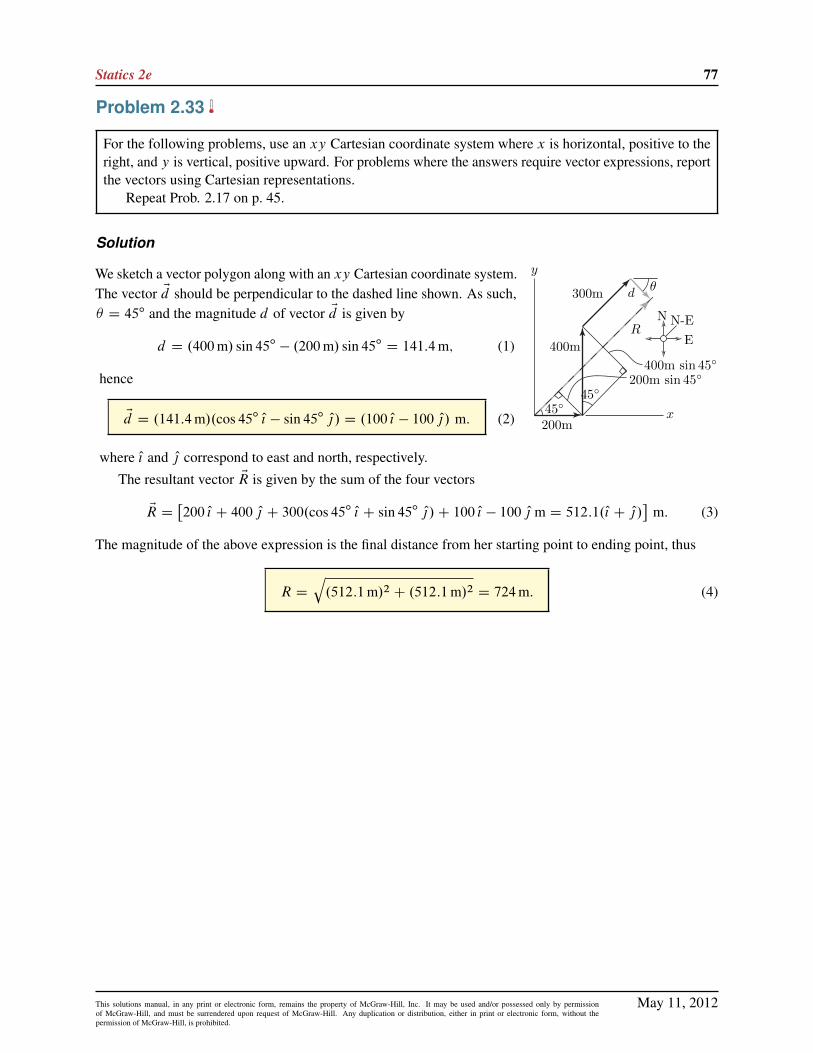
Problem 2.33
For the following problems, use an xy Cartesian coordinate system where x is horizontal, positive to theright, and y is vertical, positive upward. For problems where the answers require vector expressions, reportthe vectors using Cartesian representations.
Repeat Prob. 2.17 on p. 45.
Solution
200m
N-EE
N
400m
300m
45◦45◦
200m sin 45◦400m sin 45◦
d
y
x
R
θWe sketch a vector polygon along with an xy Cartesian coordinate system.The vector Ed should be perpendicular to the dashed line shown. As such,� D 45ı and the magnitude d of vector Ed is given by
d D .400m/ sin 45ı � .200m/ sin 45ı D 141:4m; (1)
hence
Ed D .141:4m/.cos 45ı O{ � sin 45ı O|/ D .100 O{ � 100 O|/ m: (2)
where O{ and O| correspond to east and north, respectively.
The resultant vector ER is given by the sum of the four vectors
ER D�200 O{ C 400 O| C 300.cos 45ı O{ C sin 45ı O|/C 100 O{ � 100 O| m D 512:1.O{ C O|/
�m: (3)
The magnitude of the above expression is the final distance from her starting point to ending point, thus
R D
q.512:1m/2 C .512:1m/2 D 724m: (4)
May 11, 2012This solutions manual, in any print or electronic form, remains the property of McGraw-Hill, Inc. It may be used and/or possessed only by permissionof McGraw-Hill, and must be surrendered upon request of McGraw-Hill. Any duplication or distribution, either in print or electronic form, without thepermission of McGraw-Hill, is prohibited.

78 Solutions Manual
Problem 2.34
For the following problems, use an xy Cartesian coordinate system where x is horizontal, positive to theright, and y is vertical, positive upward. For problems where the answers require vector expressions, reportthe vectors using Cartesian representations.
Repeat Prob. 2.18 on p. 45.
Solution
Part (a) Using the force polygon to the right, the resultant force ER may be writtenas
ER D��650 O{ C 400.cos 30ı O{ C sin 30ı O|/
�N D .�304 O{ C 200 O|/ N: (1)
Remark: In the solution to Prob. 2.18, the resultant force for Part (a) was called EQ.
R650 N30◦
400 N
x
y
60◦
500 N
Part (b) Using the force polygon to the right, the resultant force ER may be writtenas
ER D��650 O{ C 400.cos 30ı O{ C sin 30ı O|/C 500.cos 60ı O{ � sin 60ı O|/
�N
D .�53:6 O{ � 233 O|/ N:
(2)
R650 N30◦
400 N
x
y
60◦
P
Part (c) The resultant force vector ER is required to be vertical. Thus, we sketchthe force polygon shown at the right. Using this force polygon, the x componentof EP is
Px D 650N � .400N/ cos 30ı D 303:6N; (3)
and the y component is found by
tan 60ı D jPy=Pxj ) Py D .�303:6N/ tan 60ı D �525:8N: (4)
where the negative sign is inserted because the vertical component of EP acts in the negative y direction. Thusit follows that
P DqP 2
x C P2y D 607N: (5)
R
650 N30◦
400 N
x
yPPart (d) The 400N and 650N force vectors are shown in the force polygon at
the right along with a vertical resultant force R. The smallest value of P occurswhen this vector’s direction is perpendicular to the resultant. Thus, it follows that
P D 650N � .400N/ cos 30ı D 304N and ˛ D 0ı: (6)
May 11, 2012This solutions manual, in any print or electronic form, remains the property of McGraw-Hill, Inc. It may be used and/or possessed only by permissionof McGraw-Hill, and must be surrendered upon request of McGraw-Hill. Any duplication or distribution, either in print or electronic form, without thepermission of McGraw-Hill, is prohibited.

Statics 2e 79
Problem 2.35
For the following problems, use an xy Cartesian coordinate system where x is horizontal, positive to theright, and y is vertical, positive upward. For problems where the answers require vector expressions, reportthe vectors using Cartesian representations.
Repeat Prob. 2.21 on p. 46.
Solution
200 lb
100 lb
F1
30◦
45◦
x
yThe force polygon shown at the right includes the 100 lb and 200 lb forcevectors, along with the smallest possible force F1 such that the resultant of thethree vectors is vertical. Using this force polygon
F1 D .200 lb/ cos 45ı � .100 lb/ cos 30ı D 54:8 lb and ˛ D 90ı:
(1)
May 11, 2012This solutions manual, in any print or electronic form, remains the property of McGraw-Hill, Inc. It may be used and/or possessed only by permissionof McGraw-Hill, and must be surrendered upon request of McGraw-Hill. Any duplication or distribution, either in print or electronic form, without thepermission of McGraw-Hill, is prohibited.

80 Solutions Manual
Problem 2.36
For the following problems, use an xy Cartesian coordinate system where x is horizontal, positive to theright, and y is vertical, positive upward. For problems where the answers require vector expressions, reportthe vectors using Cartesian representations.
Repeat Prob. 2.22 on p. 46.
Solution
400 N
200 N
F1
60◦
a
x
y
30◦60◦
The dashed line in the figure to the right represents the direction along whichthe resultant force vector ER is required to act. The horizontal and verticalcomponents of ER are given by
Rx D 400N � F1 cos 30ı; and Ry D 200NC F1 sin 30ı: (1)
It follows that
tan 60ı DRy
RxD200NC F1 sin 30ı
400N � F1 cos 30ı) F1 D 246N: (2)
Note that ˛ equals 60ı since F1 is perpendicular to line a. Using Cartesian representation, EF1 is given by
EF1 D .246N/.� cos 30ı O{ C sin 30ı O|/ D .�213 O{ C 123 O|/N: (3)
May 11, 2012This solutions manual, in any print or electronic form, remains the property of McGraw-Hill, Inc. It may be used and/or possessed only by permissionof McGraw-Hill, and must be surrendered upon request of McGraw-Hill. Any duplication or distribution, either in print or electronic form, without thepermission of McGraw-Hill, is prohibited.

Statics 2e 81
Problem 2.37
Let EA D .150 O{ � 200 O|/ lb and EB D .200 O{ C 480 O|/ lb. Evaluate the following, and for Parts (a) and (b)state the magnitude of ER.
(a) ER D EAC EB .
(b) ER D 2 EA � .1=2/ EB .
(c) Find a scalar s such that ER D s EAC EB has an x component only.
(d) Determine a dimensionless unit vector in the direction EB � EA.
Solution
Part (a)
ER D .150 O{ � 200 O|/ lbC .200 O{ C 480 O|/ lb D .150C 200/O{ lbC .�200C 480/ O| lb; (1)
which simplifies to
ER D .350 O{ C 280 O|/ lb: (2)
The magnitude R is given by
R D
q.350/2 C .280/2 lb D 448 lb: (3)
Part (b)
ER D .300 O{ � 400 O|/ lb � .100 O{ C 240 O|/ lb D .300 � 100/O{ lbC .�400 � 240/ O| lb; (4)
which simplifies to
ER D .200 O{ � 640 O|/ lb: (5)
The magnitude R is given by
R D
q.200/2 C .�640/2 lb D 671 lb: (6)
Part (c)
ER D s.150 O{ � 200 O|/ lbC .200 O{ C 480 O|/ lb D .150s C 200/O{ lbC .�200s C 480/ O| lb; (7)
where, according to the problem statement,
Ry D 0 ) �200s C 480 D 0 ) s D 480=200 D 2:40: (8)
Applying this value of s to Eq. (8) yields
ER D Œ.150/.2:40/C 200� O{ lb D 560 O{ lb; R D
q.560/2 C 02 lb D 560 lb: (9)
May 11, 2012This solutions manual, in any print or electronic form, remains the property of McGraw-Hill, Inc. It may be used and/or possessed only by permissionof McGraw-Hill, and must be surrendered upon request of McGraw-Hill. Any duplication or distribution, either in print or electronic form, without thepermission of McGraw-Hill, is prohibited.

82 Solutions Manual
Part (d)
ER D Œ.200 O{ C 480 O|/ � .150 O{ � 200 O|/� lb D .50 O{ C 680 O|/ lb (10)
R D
q.50/2 C .680/2lb D 681:8 lb: (11)
The unit vector in the direction of ER is OR, and it is given by
OR DER
RD.50 O{ C 680 O|/ lb
681:8 lbD 0:0733 O{ C 0:997 O| : (12)
May 11, 2012This solutions manual, in any print or electronic form, remains the property of McGraw-Hill, Inc. It may be used and/or possessed only by permissionof McGraw-Hill, and must be surrendered upon request of McGraw-Hill. Any duplication or distribution, either in print or electronic form, without thepermission of McGraw-Hill, is prohibited.

Statics 2e 83
Problem 2.38
Let EA D .�6 O{ C 8 O|/ kN and EB D .�9 O{ � 12 O|/ kN. Evaluate the following, and for Parts (a) and (b)state the magnitude of ER.
(a) ER D EAC EB .
(b) ER D �2 EAC EB .
(c) Find a scalar s such that ER D � EAC s EB has a y component only.
(d) Determine a dimensionless unit vector in the direction EA � EB .
Solution
Part (a)
ER D EAC EB (1)
D .�6 O{ C 8 O|/ kNC .�9 O{ � 12 O|/ kN (2)
D .�6 � 9/ O{ kNC .8 � 12/ O| kN (3)
D .�15 O{ � 4 O|/ kN. (4)
The magnitude of ER is
R D
q.�15 kN/2 C .�4 kN/2 D 15:52 kN: (5)
Part (b)
ER D �2 EAC EB (6)
D �2 .�6 O{ C 8 O|/ kNC .�9 O{ � 12 O|/ kN (7)
D .12 � 9/ O{ kN C ( �16 � 12) O| kN (8)
D .3 O{ � 28 O| / kN. (9)
The magnitude of ER is
R D
q.3 kN/2 C .�28 kN/2 D 28:16 kN: (10)
Part (c)
ER D � EAC s EB (11)
D �.�6 O{ C 8 O|/ kNC s .�9 O{ � 12 O|/ kN (12)
D .6 � 9s/ O{ kN C .�8 � 12 s/ O| kN: (13)
For Eq. (13) to have a y component only, the x component must be zero. Hence
Rx D 0 ) .6 � 9s/ kN D 0 ) s D6
9D 0:6667. (14)
May 11, 2012This solutions manual, in any print or electronic form, remains the property of McGraw-Hill, Inc. It may be used and/or possessed only by permissionof McGraw-Hill, and must be surrendered upon request of McGraw-Hill. Any duplication or distribution, either in print or electronic form, without thepermission of McGraw-Hill, is prohibited.

84 Solutions Manual
Part (d)
ER D EA � EB (15)
D .�6 O{ C 8 O|/ kN � .�9 O{ � 12 O|/ kN (16)
D .3 O{ C 20 O|/ kN; (17)
R D
q.3 kN/2 C .20 kN/2 D 20:22 kN: (18)
The unit vector in the direction of ER is OR, and it is given by
OR DER
RD.3 O{ C 20 O|/ kN20:22 kN
D 0:1483 O{ C 0:9889 O| : (19)
May 11, 2012This solutions manual, in any print or electronic form, remains the property of McGraw-Hill, Inc. It may be used and/or possessed only by permissionof McGraw-Hill, and must be surrendered upon request of McGraw-Hill. Any duplication or distribution, either in print or electronic form, without thepermission of McGraw-Hill, is prohibited.

Statics 2e 85
Problem 2.39
Let EA D .150 O{ C 200 O|/mm, EB D .300 O{ � 450 O|/mm, and EC D .�100 O{ � 250 O|/mm. Evaluate thefollowing, and for Parts (a) and (b) state the magnitude of ER.
(a) ER D EAC EB C EC .
(b) ER D 3 EA � 2 EB C EC .
(c) Find scalars r and s, if possible, such that ER D r EAC s EB C EC has zero x and y components.
(d) Determine a dimensionless unit vector in the direction EAC EB C EC .
Solution
Part (a)
ER D EAC EB C EC (1)
D .150 O{ C 200 O|/mmC .300 O{ � 450 O|/mmC ( �100 O{ � 250 O| ) mm (2)
D .150C 300 � 100/ O{mmC .200 � 450 � 250/ O| mm (3)
D .350 O{ � 500 O|/mm. (4)
The magnitude of ER is
R D
q.350mm/2 C .�500mm/2 D 610:3mm: (5)
Part (b)
ER D 3 EA � 2 EB C EC (6)
D 3.150 O{ C 200 O|/mm � 2.300 O{ � 450 O|/mmC .�100 O{ � 250 O|/mm (7)
D .450 � 600 � 100/ O{mmC .600C 900 � 250/ O| mm (8)
D .�250 O{ C 1250 O|/mm. (9)
The magnitude of ER is
R D
q.�250mm/2 C .1250mm/2 D 1275mm: (10)
Part (c)
ER D r EAC s EB C EC (11)
D r.150 O{ C 200 O|/mmC s.300 O{ � 450 O|/mmC .�100 O{ � 250 O|/mm (12)
D .150 r C 300 s � 100/ O{mmC .200 r � 450 s � 250/ O| mm: (13)
May 11, 2012This solutions manual, in any print or electronic form, remains the property of McGraw-Hill, Inc. It may be used and/or possessed only by permissionof McGraw-Hill, and must be surrendered upon request of McGraw-Hill. Any duplication or distribution, either in print or electronic form, without thepermission of McGraw-Hill, is prohibited.

86 Solutions Manual
For Eq. (13) to have zero x and y components requires
150 r C 300 s � 100 D 0; (14)
200 r � 450 s � 250 D 0: (15)
We solve Eq. (14) for r to obtain
r D1
150.�300 s C 100/; (16)
and then we substitute this result into Eq. (15) to obtain
200
�1
150.�300 s C 100/
�� 450 s � 250 D 0: (17)
Solving the above equation for s provides
s D �0:1373 ; (18)
and substituting this result into Eq. (16) provides
r D 0:9412 : (19)
To check the accuracy of our solution, we substitute Eqs. (18) and (19) into Eqs. (14) and (15) to verify thatthey are satisfied.
Part (d) From Part (a),ER D EAC EB C EC D .350 O{ � 500 O|/mm: (20)
The unit vector in the direction of ER is OR, and it is given by
OR DER
RD.350 O{ � 500 O|/mm
610:3mmD 0:5735 O{ � 0:8192 O| : (21)
May 11, 2012This solutions manual, in any print or electronic form, remains the property of McGraw-Hill, Inc. It may be used and/or possessed only by permissionof McGraw-Hill, and must be surrendered upon request of McGraw-Hill. Any duplication or distribution, either in print or electronic form, without thepermission of McGraw-Hill, is prohibited.

Statics 2e 87
Problem 2.40
A rope connecting points A and B supports the force F shown in the figure.Write expressions using Cartesian vector representation for the following:
(a) ErAB : the position vector from A to B .
(b) ErBA: the position vector from B to A.
(c) OuAB : the unit vector in the direction from A to B .
(d) OuBA: the unit vector in the direction from B to A.
(e) EFAB : the force vector the rope applies to A.
(f) EFBA: the force vector the rope applies to B .
Solution
Part (a)
ErAB D .4 O{ � 3 O|/m: (1)
Part (b)
ErBA D .�4 O{ C 3 O|/m: (2)
Part (c) Using the results of Part (a), we evaluate
jErAB j D
q.4m/2 C .�3m/2 D 5m; (3)
and hence,
OuAB DErAB
jErAB jD4
5O{ �
3
5O| : (4)
Part (d)
OuBA D �OuAB D �4
5O{ C
3
5O| : (5)
Part (e)EFAB D .12 kN/ OuAB D .12 kN/
�4
5O{ �
3
5O|
�; (6)
EFAB D .9:6 O{ � 7:2 O|/ kN: (7)
Part (f) The sketch at the right shows how the forces FAB and FBA are related;namely FBA D �FAB . Thus
EFBA D �EFAB D .�9:6 O{ C 7:2 O|/ kN: (8)
May 11, 2012This solutions manual, in any print or electronic form, remains the property of McGraw-Hill, Inc. It may be used and/or possessed only by permissionof McGraw-Hill, and must be surrendered upon request of McGraw-Hill. Any duplication or distribution, either in print or electronic form, without thepermission of McGraw-Hill, is prohibited.

88 Solutions Manual
Problem 2.41
A rope connecting points A and B supports the force F shown in the figure.Write expressions using Cartesian vector representation for the following:
(a) ErAB : the position vector from A to B .
(b) ErBA: the position vector from B to A.
(c) OuAB : the unit vector in the direction from A to B .
(d) OuBA: the unit vector in the direction from B to A.
(e) EFAB : the force vector the rope applies to A.
(f) EFBA: the force vector the rope applies to B .
Solution
Part (a)
ErAB D .4 ft/�cos 30ı O{ C sin 30ı O|
�D .3:46 O{ C 2:00 O|/ ft: (1)
Part (b)
ErBA D .4 ft/�� cos 30ı O{ � sin 30ı O|
�D .�3:46 O{ � 2:00 O|/ ft: (2)
Part (c)
OuAB D cos 30ı O{ C sin 30ı O| D 0:866 O{ C 0:500 O| : (3)
Part (d)
OuBA D �OuAB D � cos 30ı O{ � sin 30ı O| D �0:866 O{ � 0:500 O| : (4)
Part (e)
EFAB D .8 lb/ OuAB D .8 lb/�cos 30ı O{ C sin 30ı O|
�; (5)
EFAB D .6:93 O{ C 4:00 O|/ lb: (6)
Part (f) The sketch at the right shows how the forces FAB and FBA arerelated; namely FBA D �FAB . Thus
EFBA D �EFAB D .�6:93 O{ � 4:00 O|/ kN: (7)
May 11, 2012This solutions manual, in any print or electronic form, remains the property of McGraw-Hill, Inc. It may be used and/or possessed only by permissionof McGraw-Hill, and must be surrendered upon request of McGraw-Hill. Any duplication or distribution, either in print or electronic form, without thepermission of McGraw-Hill, is prohibited.
Statics 2e 89
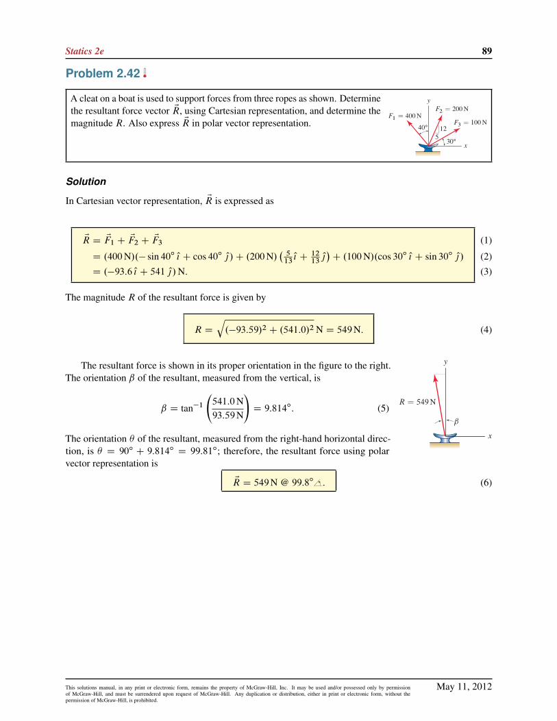
Problem 2.42
A cleat on a boat is used to support forces from three ropes as shown. Determinethe resultant force vector ER, using Cartesian representation, and determine themagnitude R. Also express ER in polar vector representation.
Solution
In Cartesian vector representation, ER is expressed as
ER D EF1 C EF2 C EF3
D .400N/.� sin 40ı O{ C cos 40ı O|/C .200N/�
513O{ C 12
13O|�C .100N/.cos 30ı O{ C sin 30ı O|/
D .�93:6 O{ C 541 O|/N:
(1)
(2)
(3)
The magnitude R of the resultant force is given by
R D
q.�93:59/2 C .541:0/2 N D 549N: (4)
The resultant force is shown in its proper orientation in the figure to the right.The orientation ˇ of the resultant, measured from the vertical, is
ˇ D tan�1
541:0N93:59N
!D 9:814ı: (5)
The orientation � of the resultant, measured from the right-hand horizontal direc-tion, is � D 90ı C 9:814ı D 99:81ı; therefore, the resultant force using polarvector representation is
ER D 549N @ 99:8ı : (6)
May 11, 2012This solutions manual, in any print or electronic form, remains the property of McGraw-Hill, Inc. It may be used and/or possessed only by permissionof McGraw-Hill, and must be surrendered upon request of McGraw-Hill. Any duplication or distribution, either in print or electronic form, without thepermission of McGraw-Hill, is prohibited.

90 Solutions Manual
Problem 2.43
A control arm in a machine supports the three forces shown. Determine theresultant force vector ER, using Cartesian representation, and determine themagnitude R. Also express ER in polar vector representation.
Solution
The resultant force is
ER D EF1 C EF2 C EF3 (1)
D 2000 lb15 O{ � 6 O|p.15/2 C .�6/2
C 1600 lb .� sin 50ı O{ � cos 50ı O|/
C 1100 lb .cos 15ı O{ � sin 15ı O|/ (2)
D .1694 O{ � 2056 O|/ lb. (3)
The magnitude of the resultant force is
R D
q.1694 lb/2 C .�2056 lb/2 D 2664 lb: (4)
yy
x
R 2664 lb
The resultant force is shown in its proper orientation to the right. The orientation� of the resultant from the horizontal direction is
� D tan�1
�2056 lb1694 lb
�D 50:52ı: (5)
Using polar vector representation, the resultant force is
ER D 2664 lb @ �50.52ı : (6)
If desired, the above resultant force may be stated using a positive angle, where 360ı � 50:52ı D 309:5ı; as
ER D 2664 lb @ 309.5ı : (7)
May 11, 2012This solutions manual, in any print or electronic form, remains the property of McGraw-Hill, Inc. It may be used and/or possessed only by permissionof McGraw-Hill, and must be surrendered upon request of McGraw-Hill. Any duplication or distribution, either in print or electronic form, without thepermission of McGraw-Hill, is prohibited.

Statics 2e 91
Problem 2.44
A cantilevered bracket supports forces from two bars and two cables, as shown.Determine the resultant force vector ER, using Cartesian representation, anddetermine the magnitude R. Also express ER in polar vector representation.
Solution
The resultant force is
ER D EF1 C EF2 C EF3 C EF4 (1)
D 600N .� cos 55ı O{ � sin 55ı O|/
C 700N.� sin 10ı O{ � cos 10ı O|/
C 800N
�13 O{ C 15 O|p.�13/2 C .15/2
!
C 900N
20 O{ C 9 O|p.20/2 C .9/2
!(2)
D .�168:9 O{ � 207:0 O|/N. (3)
The magnitude of the resultant force is
R D
q.�168:9N/2 C .�207:0N/2 D 267:2N: (4)
The resultant force is shown in its proper orientation to the right. The orientationˇ of the resultant from the horizontal direction shown is
ˇ D tan�1
�207:0N168:9N
�D 50:78ı: (5)
The orientation � of the resultant measured from the right hand horizontal directionis � D 180ı C 50:78ı D 230:8ı: Therefore, the resultant force using polar vectorrepresentation is
ER D 267:2N @ 230.8ı : (6)
May 11, 2012This solutions manual, in any print or electronic form, remains the property of McGraw-Hill, Inc. It may be used and/or possessed only by permissionof McGraw-Hill, and must be surrendered upon request of McGraw-Hill. Any duplication or distribution, either in print or electronic form, without thepermission of McGraw-Hill, is prohibited.

92 Solutions Manual
Problem 2.45
A model of a person’s arm is used for ergonomics studies. Distances are rAB D
35 cm, rBC D 28 cm, and rCD D 19 cm.(a) Determine the position vector ErAD and its magnitude rAD .
(b) Express ErAD using polar vector representation, measuring orientation posi-tive counterclockwise from the right-hand horizontal direction.
(c) Determine a unit vector OuAD in the direction from A to D.
Solution
y
x
30◦25◦
34535 cm
28 cm
19 cm
rAD
Part (a) The addition ErAD D ErAB C ErBC C ErCD gives the vectorpolygon shown at the right. Thus,
ErAD D .35 cm/.cos 30ı O{ C sin 30ı O|/C .28 cm/.�35O{ C 4
5O|/ (1)
C .19 cm/.� sin 25ı O{ C cos 25ı O|/
D .5:481 O{ C 57:12 O|/ cm; (2)
and the magnitude of this vector is given by
rAD D
q.5:481/2 C .57:12/2 cm D 57:38 cm: (3)
In summary,
ErAD D .5:48 O{ C 57:1 O|/ cm; rAD D 57:4 cm: (4)
Part (b) The orientation of ErAD measured counterclockwise from the right-hand horizontal direction is
� D � tan�1
5:481 cm57:12 cm
!D �5:481ı: (5)
Using polar vector representation, the resultant vector is
ErAD D 57:4 cm @ �5:48ı (6)
Part (c) To determine the unit vector OuAD , we use the results from Eqs. (2) and (3) to write
EuAD DErAD
rADD.5:481 O{ C 57:12 O|/ cm
57:38 cmD 0:0955 O{ C 0:995 O| : (7)
May 11, 2012This solutions manual, in any print or electronic form, remains the property of McGraw-Hill, Inc. It may be used and/or possessed only by permissionof McGraw-Hill, and must be surrendered upon request of McGraw-Hill. Any duplication or distribution, either in print or electronic form, without thepermission of McGraw-Hill, is prohibited.

Statics 2e 93
Problem 2.46
A Caterpillar Ultra High Demolition machine is shown. The distancesbetween points A and B is 12:5m, points B and C is 2:8m, C and Dis 7m, and D and E is 2:5m. Determine the position vectors ErAB , ErBC ,ErCD , and ErDE , where ErAB is the position vector from point A to pointB , and so on. Add these vectors to determine the position vector ErAE .
Solution
ErAB D 12:5m .cos 75ı O{ C sin 75ı O|/ (1)
D .3:235 O{ C 12:07 O|/m, (2)
ErBC D 2:8m
36 O{ C 15 O|p.36/2 C .15/2
!(3)
D .2:585 O{ C 1:077 O|/m, (4)
ErCD D 7m .sin 55ı O{ � cos 55ı O|/ (5)
D .5:734 O{ � 4:015 O|/m, (6)
ErDE D 2:5m
2 O{ � O|p
.2/2 C .�1/2
!(7)
D .2:236 O{ � 1:118 O|/m, (8)
ErAE D ErAB C ErBC C ErCD C ErDE (9)
D .13:79 O{ C 8:018 O|/m. (10)
May 11, 2012This solutions manual, in any print or electronic form, remains the property of McGraw-Hill, Inc. It may be used and/or possessed only by permissionof McGraw-Hill, and must be surrendered upon request of McGraw-Hill. Any duplication or distribution, either in print or electronic form, without thepermission of McGraw-Hill, is prohibited.

94 Solutions Manual
Problem 2.47
The actuator at point C of the robotic arm is positioned by specifying angles˛ and ˇ, where ˛ is measured positive counterclockwise from the positive xaxis and ˇ is measured positive clockwise from the AB direction to the BCdirection. Determine the position vector from point O to point C in terms ofangles ˛ and ˇ.
SolutionErOA D 100mm O|; (1)
ErAB D 400mm .cos˛ O{ C sin˛ O| /; (2)
ErBC D 300mm Œcos.˛ � ˇ/ O{ C sin.˛ � ˇ/ O|� ; (3)
ErOC D ErOA C ErAB C ErBC
D Œ400mm cos˛ C 300mm cos.˛ � ˇ/� O{
C Œ100mm C 400mm sin˛ C 300mm sin.˛ � ˇ/� O| :
(4)
(5)
Some simple checks may be performed to help verify the accuracy of ErOC , as follows
� If ˛ D 0 and ˇ D 0, then
ErOC D .700 O{ C 100 O|/mm. (6)
� If ˛ D 90ı and ˇ D 0ı; then
ErOC D .0 O{ C 800 O|/mm. (7)
� If ˛ D 0ı and ˇ D 90ı; then
ErOC D .400 O{ � 200 O|/mm. (8)
May 11, 2012This solutions manual, in any print or electronic form, remains the property of McGraw-Hill, Inc. It may be used and/or possessed only by permissionof McGraw-Hill, and must be surrendered upon request of McGraw-Hill. Any duplication or distribution, either in print or electronic form, without thepermission of McGraw-Hill, is prohibited.

Statics 2e 95
Problem 2.48
Two ropes are used to lift a pipe in a congested region. Determine the ratioF2=F1 so that the resultant of EF1 and EF2 is vertical.
Solution
If the resultant force ER is given by
ER D EF1 C EF2 D F1.� cos 15ı O{ C sin 15ı O|/C F2.sin 40ı O{ C cos 40ı O|/ (1)
D .�F1 cos 15ı C F2 sin 40ı/ O{ C .F1 sin 15ı C F2 cos 40ı/ O| : (2)
The problem statement asks for the x component of the resultant to be zero, thus
0 D �F1 cos 15ı C F2 sin 40ı )F2
F1D
cos 15ı
sin 40ıD 1:50: (3)
May 11, 2012This solutions manual, in any print or electronic form, remains the property of McGraw-Hill, Inc. It may be used and/or possessed only by permissionof McGraw-Hill, and must be surrendered upon request of McGraw-Hill. Any duplication or distribution, either in print or electronic form, without thepermission of McGraw-Hill, is prohibited.

96 Solutions Manual
Problem 2.49
A welded steel tab is subjected to forces F and P . Determine the largest valueP may have if F D 1000 lb and the magnitude of the resultant force cannotexceed 1500 lb.
Solution
The resultant ER of the two forces applied to the tab is
ER D EF C EP D 1000 lb.�45O{ � 3
5O|/C P.12
13O{ � 5
13O|/ (1)
D .�800 lbC P 1213/ O{ C .�600 lb � P 5
13/ O| D Rx O{ CRy O| : (2)
Given that the resultant is R D 1500 lb, and that R2 D R2x CR
2y , we may write
.1500 lb/2 D .�800 lbC P 1213/2 C .�600 lb � P 5
13/2 (3)
D .�800 lb/2 C 2.�800 lb/.P 1213/C P 2.12
13/2 (4)
C .�600 lb/2 C 2.�600 lb/.�P 513/C P 2. 5
13/2;
which may be simplified to yield
P 2�1:32 � 104 lb
13P � 1:25�106 lb2
D 0: (5)
Equation (5) is a quadratic equation, and it may be solved to obtain two solutions for P as follows
P D 12
�1:32 � 104
13˙
q.�1:32 � 104=13/2 � 4.1/.�1:25 � 106/
�lb D �720 lb; 1740 lb: (6)
The results of Eq. (6) are graphically shown in the two forcepolygons at the right. The dashed circle is drawn with a ra-dius of 1500 lb, and the resultant force vector must lie on thiscircle.
Remark: The force polygons shown at the right offer an alter-native solution to this problem. For example, with F D 1000 lband R D 1500 lb, and knowing the directions for forces F and P ,the laws of sines and cosines may be used to determine the twovalues of P obtained in Eq. (6).
May 11, 2012This solutions manual, in any print or electronic form, remains the property of McGraw-Hill, Inc. It may be used and/or possessed only by permissionof McGraw-Hill, and must be surrendered upon request of McGraw-Hill. Any duplication or distribution, either in print or electronic form, without thepermission of McGraw-Hill, is prohibited.

Statics 2e 97
Problem 2.50
The mast of a ship supports forces from three cables as shown. If F D 400 lb,determine the value of ˛ that minimizes the magnitude of the resultant of thethree forces. Also, determine the magnitude of that resultant.
Solution
The force polygon corresponding to the addition of the threeforces is shown at the right. It is constructed by first sketchingthe 600 lb and 800 lb forces, followed by force EF which has400 lb value but has direction to be determined. By examiningthe force polygon, it is seen that the resultant force ER of smallestmagnitude is obtained when EF has a direction from point B topoint O . Thus
˛ D tan�1
�45
�800 lb
600 lbC� 3
5
�800 lb
D 30:65ı. (1)
The resultant force vector is given by
ER D �600 lb O{ C 800 lb��3
5O{ C
4
5O|
�C 400 lb (cos 30.65ı O{ � sin 30.65ı O| ) (2)
D .�735:9 O{ C 436:1 O|/ lb. (3)
The magnitude of the resultant force is
R D
q.�735:9 lb/2 C .436:1 lb/2 D 855:4 lb: (4)
May 11, 2012This solutions manual, in any print or electronic form, remains the property of McGraw-Hill, Inc. It may be used and/or possessed only by permissionof McGraw-Hill, and must be surrendered upon request of McGraw-Hill. Any duplication or distribution, either in print or electronic form, without thepermission of McGraw-Hill, is prohibited.

98 Solutions Manual
Problem 2.51
The mast of a ship supports forces from three cables as shown. If ˛ D 0ı,determine the value of F that will make the magnitude of the resultant of thethree forces smallest.
Solution
The force polygon shown at the right is sketched by first drawing the600 lb and 800 lb forces. Force EF is then drawn with orientation˛ D 0ı, although its size is to be determined. Adding the three forcevectors provides the resultant force vector as
ER D �600 O{ lbC 800 lb��35O{ C
4
5O|
�C F O{: (1)
By examining the force polygon, the resultant force ER has the smallestmagnitude when its direction is perpendicular to EF . For this situation,the x component of Eq. (1) is zero, which corresponds to
Rx D �600 lbC 800 lb��3
5
�C F D 0: (2)
Thus,
F D 600 lbC 800 lb�3
5
�D 1080 lb: (3)
May 11, 2012This solutions manual, in any print or electronic form, remains the property of McGraw-Hill, Inc. It may be used and/or possessed only by permissionof McGraw-Hill, and must be surrendered upon request of McGraw-Hill. Any duplication or distribution, either in print or electronic form, without thepermission of McGraw-Hill, is prohibited.
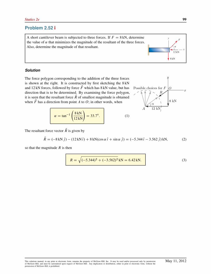
Statics 2e 99
Problem 2.52
A short cantilever beam is subjected to three forces. If F D 8 kN, determinethe value of ˛ that minimizes the magnitude of the resultant of the three forces.Also, determine the magnitude of that resultant.
Solution
8 kN
12 kN
y
x
α
Possible choices for FR
O
A
The force polygon corresponding to the addition of the three forcesis shown at the right. It is constructed by first sketching the 8 kNand 12 kN forces, followed by force EF which has 8 kN value, but hasdirection that is to be determined. By examining the force polygon,it is seen that the resultant force ER of smallest magnitude is obtainedwhen EF has a direction from point A to O; in other words, when
˛ D tan�1
8 kN12 kN
!D 33:7ı: (1)
The resultant force vector ER is given by
ER D .�8 kN O|/ � .12 kN O{/C 8 kN.cos˛ O{ C sin˛ O|/ D .�5:344 O{ � 3:562 O|/ kN; (2)
so that the magnitude R is then
R D
q.�5:344/2 C .�3:562/2 kN D 6:42 kN: (3)
May 11, 2012This solutions manual, in any print or electronic form, remains the property of McGraw-Hill, Inc. It may be used and/or possessed only by permissionof McGraw-Hill, and must be surrendered upon request of McGraw-Hill. Any duplication or distribution, either in print or electronic form, without thepermission of McGraw-Hill, is prohibited.

100 Solutions Manual
Problem 2.53
A short cantilever beam is subjected to three forces. If ˛ D 45ı, determine thevalue of F that will make the magnitude of the resultant of the three forcessmallest.
Solution
8 kN
12 kN
y
x
45◦
R
F
The force polygon shown at the right is sketched by first drawing the 8 kN and12 kN forces. Force EF is then drawn with orientation ˛ D 45ı, although its size isto be determined. Adding the three force vectors provides the resultant force ER as
ER D �.8 kN/ O| � .12 kN/ O{ C F.cos 45ı O{ C sin 45ı O|/ (1)
D .F cos 45ı � 12 kN/ O{ C .F sin 45ı � 8 kN/ O{: (2)
By examining the force polygon, the resultant force ER has the smallest magnitudewhen its direction is perpendicular to EF , thus
ER D R.� sin 45ı O{ C cos 45ı O|/: (3)
Equating the x and y terms in Eqs. (2) and (3) gives the following expressions
R.� sin 45ı/ D F cos 45ı � 12 kN ) R.�p2=2/ D F
p2=2 � 12 kN; (4)
R.cos 45ı/ D F sin 45ı � 8 kN ) R.p2=2/ D F
p2=2 � 8 kN: (5)
The above equations can be solved for F by simply adding them to obtain
0 Dp2F � 20 kN ) F D
20 kNp2D 14:1 kN: (6)
May 11, 2012This solutions manual, in any print or electronic form, remains the property of McGraw-Hill, Inc. It may be used and/or possessed only by permissionof McGraw-Hill, and must be surrendered upon request of McGraw-Hill. Any duplication or distribution, either in print or electronic form, without thepermission of McGraw-Hill, is prohibited.

Statics 2e 101
Problem 2.54
An eyebolt is loaded by forces F1 and F2. If the eyebolt has a maximumworking load of 1200 lb, determine if the working load multipliers given inFig. 1 of Example 2.6 are met for the following loading scenarios:
(a) Only F1 is applied.
(b) Only F2 is applied.
(c) Both F1 and F2 are applied simultaneously.
Solution
For convenience, the table of working load multipliers from Fig. 1 ofExample 2.6 is repeated in the figure at the right.
Part (a) When only F1 is applied, the net force is oriented at an angle˛1 from the horizontal, where
˛1 D tan�1 .8=15/ D 28:07ı: (1)
The orientation of F1 from the vertical (i.e., axis of eyebolt) is therefore
�1 D 90ı� ˛1 D 61:93
ı: (2)
Consulting the table of load multipliers, the working load multiplier for �1 D 61:93ı is 20%. The maximum
force the eyebolt may be subjected to is .1200 lb/.0:20/ D 240 lb; since this value is larger than F1 D 200 lb,the eyebolt is safe when only F1 is applied. Hence,
This design is safe when only F1 is applied.
Part (b) When only F2 is applied, the net force is oriented at an angle ˛2 from the horizontal, where
˛2 D tan�1 .12=5/ D 67:38ı: (3)
The orientation of F2 from the vertical (i.e., axis of eyebolt) is therefore
�2 D 90ı� ˛2 D 22:62
ı: (4)
Consulting the table of load multipliers, the working load multiplier for �2 D 22:62ı is 60%. The maximum
force the eyebolt may be subjected to is .1200 lb/.0:60/ D 720 lb; since this value is smaller thanF2 D 800 lb,the eyebolt is not safe when only F2 is applied. Hence,
This design is not safe when only F2 is applied:
May 11, 2012This solutions manual, in any print or electronic form, remains the property of McGraw-Hill, Inc. It may be used and/or possessed only by permissionof McGraw-Hill, and must be surrendered upon request of McGraw-Hill. Any duplication or distribution, either in print or electronic form, without thepermission of McGraw-Hill, is prohibited.

102 Solutions Manual
Part (c) The resultant force is
ER D EF1 C EF2 (5)
D 200 lb��15 O{ C 8 O|
17
�C 800 lb
�5 O{ C 12 O|
13
�(6)
D .131:2 O{ C 832:6 O|/ lb: (7)
The magnitude of ER and its orientation from the horizontal are
R D
q.131:2 lb/2 C .832:6 lb/2 D 842:9 lb; (8)
˛3 D tan�1.832:6 lb=131:2 lb/ D 81:04ı: (9)
The orientation of ER from the vertical (i.e., axis of eyebolt) is therefore
�3 D 90ı� ˛3 D 8:957
ı: (10)
Consulting the table of load multipliers, the working load multiplier for �3 D 8:957ı is 100%. The maximum
force the eyebolt may be subjected to is .1200 lb/.1/ D 1200 lb; since this value is larger than R D 842:9 lb,the eyebolt is safe when F1 and F2 are applied simultaneously. Hence,
This design is safe when both F1 and F2 are applied simultaneously:
May 11, 2012This solutions manual, in any print or electronic form, remains the property of McGraw-Hill, Inc. It may be used and/or possessed only by permissionof McGraw-Hill, and must be surrendered upon request of McGraw-Hill. Any duplication or distribution, either in print or electronic form, without thepermission of McGraw-Hill, is prohibited.
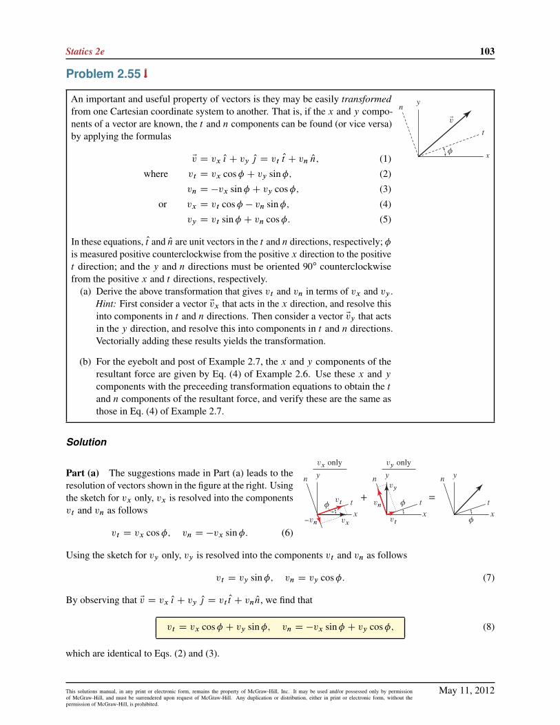
Statics 2e 103
Problem 2.55
An important and useful property of vectors is they may be easily transformedfrom one Cartesian coordinate system to another. That is, if the x and y compo-nents of a vector are known, the t and n components can be found (or vice versa)by applying the formulas
Ev D vx O{ C vy O| D vt Ot C vn On; (1)
where vt D vx cos� C vy sin�; (2)
vn D �vx sin� C vy cos�; (3)
or vx D vt cos� � vn sin�; (4)
vy D vt sin� C vn cos�: (5)
In these equations, Ot and On are unit vectors in the t and n directions, respectively; �is measured positive counterclockwise from the positive x direction to the positivet direction; and the y and n directions must be oriented 90ı counterclockwisefrom the positive x and t directions, respectively.
(a) Derive the above transformation that gives vt and vn in terms of vx and vy .Hint: First consider a vector Evx that acts in the x direction, and resolve thisinto components in t and n directions. Then consider a vector Evy that actsin the y direction, and resolve this into components in t and n directions.Vectorially adding these results yields the transformation.
(b) For the eyebolt and post of Example 2.7, the x and y components of theresultant force are given by Eq. (4) of Example 2.6. Use these x and ycomponents with the preceeding transformation equations to obtain the tand n components of the resultant force, and verify these are the same asthose in Eq. (4) of Example 2.7.
Solution
Part (a) The suggestions made in Part (a) leads to theresolution of vectors shown in the figure at the right. Usingthe sketch for vx only, vx is resolved into the componentsvt and vn as follows
vt D vx cos�; vn D �vx sin�: (6)
Using the sketch for vy only, vy is resolved into the components vt and vn as follows
vt D vy sin�; vn D vy cos�: (7)
By observing that Ev D vx O{ C vy O| D vt Ot C vn On, we find that
vt D vx cos� C vy sin�; vn D �vx sin� C vy cos�; (8)
which are identical to Eqs. (2) and (3).
May 11, 2012This solutions manual, in any print or electronic form, remains the property of McGraw-Hill, Inc. It may be used and/or possessed only by permissionof McGraw-Hill, and must be surrendered upon request of McGraw-Hill. Any duplication or distribution, either in print or electronic form, without thepermission of McGraw-Hill, is prohibited.

104 Solutions Manual
Part (b) The resultant force in terms of x and y components was found to be
Rx D �809:9 lb; Ry D 373:9 lb: (9)
Since the t axis is rotated 40ı counterclockwise from the x axis, � D 40ı, and Eqs. (2) and (3) provide
Rt D .�809:9 lb/ cos 40ı C .373:9 lb/ sin 40ı D �380:0 lb;
Rn D .�809:9 lb/ sin 40ı C .373:9 lb/ cos 40ı D 807:0 lb;
(10)
(11)
with agree with Eq. (5) from Example 2.7 on page 52.
May 11, 2012This solutions manual, in any print or electronic form, remains the property of McGraw-Hill, Inc. It may be used and/or possessed only by permissionof McGraw-Hill, and must be surrendered upon request of McGraw-Hill. Any duplication or distribution, either in print or electronic form, without thepermission of McGraw-Hill, is prohibited.

Statics 2e 105
Problem 2.56
A box weighing 200N rests on an inclined surface. A worker applies a hori-zontal force F to help position the box. Determine the x and y components ofthe resultant of forces W and F . Also determine the t and n components ofthe resultant force vector. Comment on why the t and n components might beuseful to know.
Solution
The resultant ER of the forces EF and EW applied to the box is
ER D EF C EW D 100N O{ � 200N O|; (1)
and the components of this resultant force are
Rx D 100N; Ry D �200N: (2)
The magnitude of ER is
R D
q.100N/2 C�200N/2 D 223:6N: (3)
Using the sketch at the right, we first determine the 26.57ı angle, whichthen allows the angle ˛ D 3:43ı to be determined. Then, knowing that theresultant force is 223:6N, the t and n components of the resultant force maybe determined as
Rt D �R sin˛ D .�223:6N/ sin 3:43ı D �13:40N;
Rn D �R cos˛ D .�223:6N/ cos 3:43ı D �223:2N:
(4)
(5)
The t and n components are needed to determine if the box will slide usingCoulomb’s law of friction.
Alternate solution The t and n components of the resultant force may also be determined using vectortransformation concepts. Using Eqs. (2) and (3) described in Problem 2.55, with � D 30ı, we find that
Rt D .100N/ cos 30ı C .�200N/ sin 30ı D �13:40N;
Rn D �.100N/ sin 30ı C .�200N/ cos 30ı D �223:2N:
(6)
(7)
May 11, 2012This solutions manual, in any print or electronic form, remains the property of McGraw-Hill, Inc. It may be used and/or possessed only by permissionof McGraw-Hill, and must be surrendered upon request of McGraw-Hill. Any duplication or distribution, either in print or electronic form, without thepermission of McGraw-Hill, is prohibited.

106 Solutions Manual
Problem 2.57
A motor-driven gear is used to produce forces P1 and P2 in members AB andAC of a machine. Member AC is parallel to the y axis.
(a) Determine the x and y components of the resultant force vector at A dueto forces P1 and P2.
(b) Determine the t and n components of the resultant force vector. Commenton why the t and n components might be useful to know.
Solution
Part (a) The resultant force vector is given by ER D EP1 C EP2. Thus
ER D .200 lb/.cos 30ı O{ � sin 30ı O|/C 50 lb .� O|/ D .173:2 O{ � 150:0 O|/ lb; (1)
the components of the resultant force are
Rx D 173 lb; Ry D �150 lb; (2)
and the magnitude of ER is
R D
q.173:2/2 C .�150:0/2 lb D 229:1 lb: (3)
R
Part (b) Using the figure to the right, the angles ˛ and ˇ are given by
˛ D tan�1.150:0 lb=173:2 lb/ D 40:89ı; ˇ D 90ı � 30ı � ˛ D 19:11ı: (4)
The t and n components of ER may be found using angle ˇ as
Rt D R cosˇ D .229:1 lb/ cos 19:11ı D 217 lb;
Rn D R sinˇ D .229:1 lb/ sin 19:11ı D 75:0 lb:
(5)
(6)
Alternate solution Rt and Rn may be determined using vector transformation concepts. Using Eqs. (2)and (3) described in Prob. 2.55, with � D �60ı, we obtain
Rt D .173:2 lb/ cos.�60ı/C .�150 lb/ sin.�60ı/ D 217 lb; (7)
Rn D �.173:2 lb/ sin.�60ı/C .�150 lb/ cos.�60ı/ D 75:0 lb: (8)
May 11, 2012This solutions manual, in any print or electronic form, remains the property of McGraw-Hill, Inc. It may be used and/or possessed only by permissionof McGraw-Hill, and must be surrendered upon request of McGraw-Hill. Any duplication or distribution, either in print or electronic form, without thepermission of McGraw-Hill, is prohibited.

Statics 2e 107
Problem 2.58
Traction is a medical procedure used to treat muscle and skeletal disorders bystrategically applying one or more forces to a person’s body for a specific lengthof time.
(a) Determine the x and y components of the resultant force vector at A dueto the 40N and 60N forces.
(b) Determine the t and n components of the resultant force vector.
Solution
Part (a)
ER D 40N.�cos 35ı O{ C sin 35ı O|/
C 60 N (cos 25ı O{ C sin 25ı O| ) (1)
D .21:61 O{ C 48:30 O|/N: (2)
Thus, the x and y components are
Rx D 21:61N and Ry D 48:30N: (3)
60 N
40°t
n
Ay
x
20°
40 NPart (b) The figure to the right has angles defined with respect to thet direction. Repeating the solution procedure from Part (a) provides
ER D 40N ( � cos 20ı Ot C sin 20ı On)
C 60N (cos 40ı Ot C sin 40ı On) (4)
D .8:375 Ot C 52:25 On/N: (5)
Thus, the t and n components of the resultant force are
Rt D 8:375N and Rn D 52:25N: (6)
As a partial check of solution accuracy, we may verify that Eqs. (3) and (5) have the same magnitude.
Alternate Solution Rt and Rn may be determined using vector transformation concepts. Using Eqs. (2)and (3) described in Prob. 2.55, with � D �15ı; we obtain
Rt D .21:61N/ cos.�15ı/C .48:30N/ sin.�15ı/ D 8:375N; (7)
Rn D �.21:61N/ sin.�15ı/C .48:30N/ cos.�15ı/ D 52:25N: (8)
May 11, 2012This solutions manual, in any print or electronic form, remains the property of McGraw-Hill, Inc. It may be used and/or possessed only by permissionof McGraw-Hill, and must be surrendered upon request of McGraw-Hill. Any duplication or distribution, either in print or electronic form, without thepermission of McGraw-Hill, is prohibited.

108 Solutions Manual
Problem 2.59
A structure supports forces from a bar and cable as shown.(a) Determine the x and y components of the resultant force vector at A due
to the 6 kip and 10 kip forces.
(b) Determine the t and n components of the resultant force vector.
Solution
Part (a)
ER D 6 kip ( � cos 70ı O{ � sin 70ı O| )
C 10 kip (cos 40ı O{ � sin 40ı O| ) (1)
D .5:608 O{ � 12:07 O|/ kip: (2)
Thus, the x and y components are
Rx D 5:608 kip and Ry D �12:07 kip: (3)
n
6 kip
50°
60°
10 kip
tAx
yPart (b) The figure to the right has angles defined with respect to the tdirection. Repeating the solution procedure from Part (a) provides
ER D 6 kip ( � cos 50ı Ot � sin 50ı On)
C 10 kip .cos 60ı Ot � sin 60ı On/ (4)
D .1:143Ot � 13:26 On/ kip: (5)
Thus, the t and n components of the resultant force are
Rt D 1:143 kip and Rn D �13:26 kip: (6)
As a partial check of solution accuracy, we may verify that Eqs. (3) and (5) have the same magnitude.
Alternate solution Rt and Rn may be determined using vector transformation concepts. Using Eqs. (2)and (3) described in Prob. 2.55, with � D 20ı; we obtain
Rt D .5:608 kip/ cos 20ı C .�12:07 kip/ sin 20ı D 1:143 kip; (7)
Rn D �.5:608 kip/ sin 20ı C .�12:07 kip/ cos 20ı D �13:26 kip: (8)
May 11, 2012This solutions manual, in any print or electronic form, remains the property of McGraw-Hill, Inc. It may be used and/or possessed only by permissionof McGraw-Hill, and must be surrendered upon request of McGraw-Hill. Any duplication or distribution, either in print or electronic form, without thepermission of McGraw-Hill, is prohibited.

Statics 2e 109
Problem 2.60
Two people apply forces P1 and P2 to the handle of a wrench as shown.(a) Determine the x and y components of the resultant force vector applied
to the handle of the wrench.
(b) Determine the t and n components of the resultant force vector. Commenton why the t and n components might be useful to know.
Solution
Part (a) The resultant force is given by ER D EP1 C EP2, where
ER D .80N/.� cos 20ı O{ C sin 20ı O|/C .140N/.� cos 10ı O{ C sin 10ı O|/ D .�213:0 O{ C 51:67 O|/N; (1)
so that the components of the resultant force are
Rx D �213N; Ry D 51:7N: (2)
The magnitude of ER is
R D
q.�213:0/2 C .51:67/2 N D 219:2N: (3)
Part (b) Using the figure to the right, the angles ˛ and ˇ are
˛ D tan�1.51:67N=213:0N/ D 13:63ı; ˇ D 45ı � ˛ D 31:37ı: (4)
The t and n components of ER may be found using ˇ as
Rt D �R cosˇ D �.219:2N/ cos 31:37ı D �187N;
Rn D �R sinˇ D �.219:2N/ sin 31:37ı D �114N:
(5)
(6)
Alternate solution Rt and Rn may be determined using vector transfor-mation concepts. Using Eqs. (2) and (3) described in Problem 2.55, with� D 315ı, or with � D �45ı, we obtain
Rt D .�213:0N/ cos.�45ı/C .51:67N/ sin.�45ı/ D �187N; (7)
Rn D �.�213:0N/ sin.�45ı/C .51:67N/ cos.�45ı/ D �114N: (8)
May 11, 2012This solutions manual, in any print or electronic form, remains the property of McGraw-Hill, Inc. It may be used and/or possessed only by permissionof McGraw-Hill, and must be surrendered upon request of McGraw-Hill. Any duplication or distribution, either in print or electronic form, without thepermission of McGraw-Hill, is prohibited.
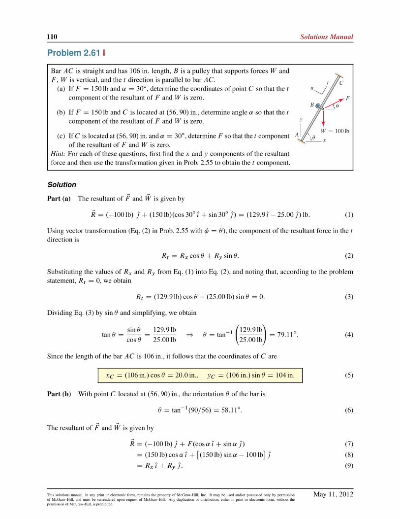
110 Solutions Manual
Problem 2.61
Bar AC is straight and has 106 in. length, B is a pulley that supports forces W andF , W is vertical, and the t direction is parallel to bar AC:
(a) If F D 150 lb and ˛ D 30ı, determine the coordinates of point C so that the tcomponent of the resultant of F and W is zero.
(b) If F D 150 lb and C is located at .56; 90/ in., determine angle ˛ so that the tcomponent of the resultant of F and W is zero.
(c) IfC is located at .56; 90/ in. and ˛ D 30ı, determineF so that the t componentof the resultant of F and W is zero.
Hint: For each of these questions, first find the x and y components of the resultantforce and then use the transformation given in Prob. 2.55 to obtain the t component.
Solution
Part (a) The resultant of EF and EW is given by
ER D .�100 lb/ O| C .150 lb/.cos 30ı O{ C sin 30ı O|/ D .129:9 O{ � 25:00 O|/ lb: (1)
Using vector transformation (Eq. (2) in Prob. 2.55 with � D � ), the component of the resultant force in the tdirection is
Rt D Rx cos � CRy sin �: (2)
Substituting the values of Rx and Ry from Eq. (1) into Eq. (2), and noting that, according to the problemstatement, Rt D 0, we obtain
Rt D .129:9 lb/ cos � � .25:00 lb/ sin � D 0: (3)
Dividing Eq. (3) by sin � and simplifying, we obtain
tan � Dsin �cos �
D129:9 lb25:00 lb
) � D tan�1
129:9 lb25:00 lb
!D 79:11ı: (4)
Since the length of the bar AC is 106 in:, it follows that the coordinates of C are
xC D .106 in:/ cos � D 20:0 in:; yC D .106 in:/ sin � D 104 in: (5)
Part (b) With point C located at .56; 90/ in., the orientation � of the bar is
� D tan�1.90=56/ D 58:11ı: (6)
The resultant of EF and EW is given by
ER D .�100 lb/ O| C F.cos˛ O{ C sin˛ O|/ (7)
D .150 lb/ cos˛ O{ C�.150 lb/ sin˛ � 100 lb
�O| (8)
D Rx O{ CRy O| : (9)
May 11, 2012This solutions manual, in any print or electronic form, remains the property of McGraw-Hill, Inc. It may be used and/or possessed only by permissionof McGraw-Hill, and must be surrendered upon request of McGraw-Hill. Any duplication or distribution, either in print or electronic form, without thepermission of McGraw-Hill, is prohibited.

Statics 2e 111
2
0
-2
-4
1◦ 2◦ 4◦3◦
Rt (lb)
α
α ≈ 2.584◦Using vector transformation (Eq. (2) in Prob. 2.55 with � D � D
58:11ı), the component of the resultant force in the t direction, whichis zero according to the problem statement, is
Rt D .150 lb/.cos˛/.cos 58:11ı/
C .150 lb sin˛ � 100 lb/.sin 58:11ı/ D 0; (10)
Equation (10) has one unknown, namely ˛, and the equation maybe solved using computer algebra software (e.g., Mathematica orMaple), by trial and error, or by simply plotting Rt versus ˛, as shown at the right. In this plot, the locationwhere Rt D 0 corresponds to
˛ D 2:58ı: (11)
Part (c) With point C located at .56; 90/ in., the orientation � of the bar is given by Eq. (6), namely� D 58:11ı. The resultant of EF and EW is given by
ER D .�100 lb/ O| C F.cos 30ı O{ C sin 30ı O|/ (12)
D F cos 30ı O{ C .F sin 30ı � 100 lb/ O| (13)
D Rx O{ CRy O| : (14)
Using vector transformation (Eq. (2) in Prob. 2.55 with � D � D 58:11ı), the component of the resultantforce in the t direction, which is zero according to the problem statement, is
Rt D F.cos 30ı/.cos 58:11ı/C .F sin 30ı � 100 lb/.sin 58:11ı/ D 0: (15)
Solving Eq. (15) for F , we find that
F�.cos 30ı/.cos 58:11ı/C .sin 30ı/.sin 58:11ı/
�D .100 lb/.sin 58:11ı/ ) F D 96:3 lb (16)
May 11, 2012This solutions manual, in any print or electronic form, remains the property of McGraw-Hill, Inc. It may be used and/or possessed only by permissionof McGraw-Hill, and must be surrendered upon request of McGraw-Hill. Any duplication or distribution, either in print or electronic form, without thepermission of McGraw-Hill, is prohibited.

112 Solutions Manual
Problem 2.62
Screw AC is used to position point D of a machine. Points A and C havecoordinates .185; 0/mm and .125; 144/mm, respectively, and are fixed in spaceby the bearings that support the screw. If point B is 52mm from point A,determine the position vector ErAB and the coordinates of point B .
Solution
Begin by determining the vector ErAC (where point C is the head of the vector and point A is the tail):
ErAC D ..125 � 185/ O{ C .144 � 0/ O|/ mm D .�60 O{ C 144 O|/mm: (1)
The magnitude of ErAC is given by
rAC D
q.�60mm/2 C .144mm/2 D 156mm: (2)
The unit vector in the AB direction is given by ErAC =rAC , and hence the position vector ErAB is
ErAB D 52mmErAC
rACD 52mm
�60mm O{ C 144mm O|156mm
D .�20 O{ C 48 O|/mm: (3)
To determine the coordinates of point B , we write an expression for the position vector ErAB by taking thedifferences of the coordinates of the head and tail. With points B and A having coordinates .xB ; yB/ and(185:0mm, 0), respectively, we obtain
ErAB D .xB � 185mm/ O{ C .yB � 0/ O| : (4)
For Eqs. (3) and (4) to agree requires that
�20mm D xB � 185mm ) xB D 165mm; 48mm D yB � 0mm ) yB D 48mm:
(5)
May 11, 2012This solutions manual, in any print or electronic form, remains the property of McGraw-Hill, Inc. It may be used and/or possessed only by permissionof McGraw-Hill, and must be surrendered upon request of McGraw-Hill. Any duplication or distribution, either in print or electronic form, without thepermission of McGraw-Hill, is prohibited.

Statics 2e 113
Problem 2.63
Repeat Prob. 2.62 if point B is 39mm from point C .
Solution
Begin by determining the vector ErCA (where point A is the head of the vector and point C is the tail):
ErCA D .185mm � 125mm/ O{ C .0 � 144mm/ O| D .60 O{ � 144 O|/mm: (1)
The magnitude of ErCA is given by
rCA D
q.60mm/2 C .�144mm/2 D 156mm: (2)
The unit vector in the CB direction is given by ErCA=rCA, and hence the position vector ErCB is
ErCB D 39mmErCA
rCAD 39mm
.60 O{ � 144 O|/mm156mm
D .15 O{ � 36 O|/mm: (3)
To determine the coordinates of point B , we write an expression for the position vector ErCB by taking thedifferences of the coordinates of the head and tail. With points B and C having coordinates .xB ; yB/ and.125; 144/mm, respectively, we obtain
ErCB D .xB � 125mm/ O{ C .yB � 144mm/ O| : (4)
For Eqs. (3) and (4) to agree requires that
15mm D xB � 125mm ) xB D 140mm; �36mm D yB � 144mm ) yB D 108mm:
(5)
May 11, 2012This solutions manual, in any print or electronic form, remains the property of McGraw-Hill, Inc. It may be used and/or possessed only by permissionof McGraw-Hill, and must be surrendered upon request of McGraw-Hill. Any duplication or distribution, either in print or electronic form, without thepermission of McGraw-Hill, is prohibited.

114 Solutions Manual
Problem 2.64
ScrewAC is used to position pointD of a machine. PointA has coordinates .185; 0/mm and is fixed in space by a bearing that supports the screw. The screw nut at pointB is supported by lever ED and at the instant shown has coordinates .160; 60/mm.If the length of the screw from A to C is 130mm, determine the position vector ErAC
and the coordinates of point C .
Solution
Begin by determining the vector ErAB (where point B is the head of the vector and point A is the tail):
ErAB D .160mm � 185mm/ O{ C .60mm � 0/ O| D .�25 O{ C 60 O|/mm: (1)
The magnitude of ErAB is given by
rAB D
q.�25mm/2 C .60mm/2 D 65mm: (2)
The unit vector in the AC direction is given by ErAB=rAB , and hence the position vector ErAC is
ErAC D 130mmErAB
rABD 130mm
.�25 O{ C 60 O|/mm65mm
D .�50 O{ C 120 O|/mm: (3)
To determine the coordinates of point C , we write an expression for the position vector ErAC by taking thedifferences of the coordinates of the head and tail. With points C and A having coordinates .xC ; yC / and.185; 0/mm, respectively, we obtain
ErAC D .xC � 185mm/ O{ C .yC � 0/ O| : (4)
For Eqs. (3) and (4) to agree requires that
�50mm D xC � 185mm ) xC D 135mm; 120mm D yC � 0mm ) yC D 120mm:
May 11, 2012This solutions manual, in any print or electronic form, remains the property of McGraw-Hill, Inc. It may be used and/or possessed only by permissionof McGraw-Hill, and must be surrendered upon request of McGraw-Hill. Any duplication or distribution, either in print or electronic form, without thepermission of McGraw-Hill, is prohibited.

Statics 2e 115
Problem 2.65
In Prob. 2.64 if point B is equidistant from points A and C and if ErEA D
.185 O{ � 50 O|/mm and ErEB D .155 O{ C 22 O|/mm, determine the position vectorErAC .
Solution
The vector polygon shown at the right corresponds to the vector expressionErAB D ErAE C ErEB . Thus
ErAB D ErAE C ErEB (1)
D �ErEA C ErEB (2)
D �.185 O{ � 50 O|/mmC .155 O{ C 22 O|/mm (3)
D .�30 O{ C 72 O|/mm: (4)
Since point B is equidistant from points A and C , it follows that
ErAC D 2 ErAB D .�60 O{ C 144 O|/mm:
May 11, 2012This solutions manual, in any print or electronic form, remains the property of McGraw-Hill, Inc. It may be used and/or possessed only by permissionof McGraw-Hill, and must be surrendered upon request of McGraw-Hill. Any duplication or distribution, either in print or electronic form, without thepermission of McGraw-Hill, is prohibited.

116 Solutions Manual
Problem 2.66
A computer numerical control (CNC) milling machine is used to cut a slotin the component shown. The cutting tool starts at point A and advances topoint B where it pauses while the depth of cut is increased, and then the toolcontinues on to point C . If the coordinates of points A and C are .95; 56/mmand .17; 160/mm, respectively, and B is located 45mm from A, determine theposition vectors ErOA, ErOB , and ErOC and the coordinates of B .
Solution
With the coordinates provided in the problem statement, the following three position vectors may immediatelybe written:
ErOA D .95 O{ C 56 O|/mm; ErOB D xB O{ C yB O|; ErOC D .17 O{ C 160 O|/mm: (1)
Using these vectors, we may determine ErAC using
ErAC D ErAO C ErOC (2)
D �ErOA C ErOC (3)
D �.95 O{ C 56 O|/mmC .17 O{ C 160 O|/mm (4)
D .�78 O{ C 104 O|/mm: (5)
The magnitude of ErAB is given in the problem statement to be 45mm, and thus we may write
ErAB D 45mmErAC
rACD 45mm
.�78 O{ C 104 O|/mmp.�78/2 C .104/2 mm
D .�27 O{ C 36 O|/mm: (6)
An expression for ErOB may be written as
ErOB D ErOA C ErAB (7)
D .95 O{ C 56 O|/mmC .�27 O{ C 36 O|/mm (8)
D .68 O{ C 92 O|/mm: (9)
For Eq. (9) to agree with the expression for ErOB in Eq. (1) requires that
xB D 68mm and yB D 92mm; (10)
and with these coordinates, ErOB in Eq. (1) becomes
ErOB D .68 O{ C 92 O|/mm: (11)
May 11, 2012This solutions manual, in any print or electronic form, remains the property of McGraw-Hill, Inc. It may be used and/or possessed only by permissionof McGraw-Hill, and must be surrendered upon request of McGraw-Hill. Any duplication or distribution, either in print or electronic form, without thepermission of McGraw-Hill, is prohibited.

Statics 2e 117
Problem 2.67
A vector Er has the two direction angles given below. Determine the possible values for the third directionangle, and describe the differences in the orientation of Er . Provide a sketch showing these different vectors.
�x D 36ı and �y D 72
ı.
Solution
The direction angle �´ may be determined using
cos2 �x C cos2 �y C cos2 �´ D 1; (1)
�´ D cos�1˙
q1 � cos2 �x � cos2 �y (2)
D cos�1˙
p
1 � cos2 36ı � cos2 72ı (3)
D cos�1˙ 0:5 : (4)
Although there are an infinite number of solutions to the above equation for �´, there are only two solutionsin the interval 0ı � �´ � 180
ı, and these are
�´ D 60ı; 120ı: (5)
To show the vectors associated with these two solutions,consider the following two unit vectors for �x and �y
given in the problem statement, and �´ D 60ı and 120ı:
Ou1 D cos.36ı/ O{ C cos.72ı/ O| C cos.60ı/ Ok (6)
D 0:8090 O{ C 0:3090 O| C 0:5000 Ok; (7)
Ou2 D cos.36ı/ O{ C cos.72ı/ O| C cos.120ı/ Ok (8)
D 0:8090 O{ C 0:3090 O| � 0:5000 Ok: (9)
These two vectors are shown at the right, where the different �´ values change the sign of the ´-component.
May 11, 2012This solutions manual, in any print or electronic form, remains the property of McGraw-Hill, Inc. It may be used and/or possessed only by permissionof McGraw-Hill, and must be surrendered upon request of McGraw-Hill. Any duplication or distribution, either in print or electronic form, without thepermission of McGraw-Hill, is prohibited.

118 Solutions Manual
Problem 2.68
A vector Er has the two direction angles given below. Determine the possible values for the third directionangle, and describe the differences in the orientation of Er . Provide a sketch showing these different vectors.
�y D 60ı and �´ D 108
ı.
Solution
The direction angle �x may be determined using
cos2 �x C cos2 �y C cos2 �´ D 1; (1)
�x D cos�1˙
q1 � cos2 �y � cos2 �´ (2)
D cos�1˙
p
1 � cos2 60ı � cos2 108ı (3)
D cos�1˙ 0:8090 : (4)
Although there are an infinite number of solutions to the above equation, the only two solutions in the interval0ı � �x � 180
ı are
�x D 36ı; 144ı: (5)
To show the vectors associated with these two solutions, consider the following two unit vectors for �y and�´ as given in the problem statement, and �x D 36
ı and 144ı:
Ou1 D cos 36ı O{ C cos 60ı O| C cos 108ı Ok (6)
D 0:8090 O{ C 0:5 O| � 0:3090 Ok; (7)
Ou2 D cos 144ı O{ C cos 60ı O| C cos 108ı Ok (8)
D �0:8090 O{ C 0:5 O| � 0:3090 Ok: (9)
These two vectors are shown below, where the different �x values change the sign of the x component.
May 11, 2012This solutions manual, in any print or electronic form, remains the property of McGraw-Hill, Inc. It may be used and/or possessed only by permissionof McGraw-Hill, and must be surrendered upon request of McGraw-Hill. Any duplication or distribution, either in print or electronic form, without thepermission of McGraw-Hill, is prohibited.

Statics 2e 119
Problem 2.69
A vector Er has the two direction angles given below. Determine the possible values for the third directionangle, and describe the differences in the orientation of Er . Provide a sketch showing these different vectors.
�x D 150ı and �´ D 100
ı.
Solution
The direction angle �y may be determined using
cos2 �x C cos2 �y C cos2 �´ D 1; (1)
�y D cos�1˙
q1 � cos2 �x � cos2 �y (2)
D cos�1˙
p
1 � cos2 150ı � cos2 100ı (3)
D cos�1˙ 0:4689 : (4)
Although there are an infinite number of solutions to the above equation, the only two solutions in the interval0ı � �y � 180
ı are
�y D 62:04ı; 118:0ı: (5)
To show the vectors associated with these two solutions, consider the following two unit vectors for �x and�´ as given in the problem statement, and �y D 62:04
ı and 118:0ı:
Ou1 D cos 150ı O{ C cos 62:04ı O| C cos 100ı Ok (6)
D �0:8660 O{ C 0:4689 O| � 0:1736 Ok; (7)
Ou2 D cos 150ı O{ C cos 118:0ı O| C cos 100ı Ok (8)
D �0:8660 O{ � 0:4689 O| � 0:1736 Ok: (9)
These two vectors are shown below, where the different �y values change the sign of the y component.
y
x
z
1
2
0.1736
0.4689
0.17360.4689
0.8660
May 11, 2012This solutions manual, in any print or electronic form, remains the property of McGraw-Hill, Inc. It may be used and/or possessed only by permissionof McGraw-Hill, and must be surrendered upon request of McGraw-Hill. Any duplication or distribution, either in print or electronic form, without thepermission of McGraw-Hill, is prohibited.

120 Solutions Manual
Problem 2.70
Consider a vector En that makes equal angles with the x, y, and ´ axes (i.e., �x D �y D �´). Determine thevalue of these angles and the value of the direction cosines. Note: In the study of stresses in mechanics ofmaterials, the direction En plays an important role and is the normal direction to a special surface called theoctahedral plane.
Solution
The direction angles all have the same value. Using the equation
cos2 �x C cos2 �y C cos2 �´ D 1; (1)
with � D �x D �y D �´; we obtain3 cos2 � D 1: (2)
Solving this provides the direction cosines as
cos � D ˙
r1
3D ˙ 0:5774; (3)
and the direction angles are
� D cos�1˙
r1
3(4)
D 54:74ı; 125:3ı. (5)
May 11, 2012This solutions manual, in any print or electronic form, remains the property of McGraw-Hill, Inc. It may be used and/or possessed only by permissionof McGraw-Hill, and must be surrendered upon request of McGraw-Hill. Any duplication or distribution, either in print or electronic form, without thepermission of McGraw-Hill, is prohibited.

Statics 2e 121
Problem 2.71
A person of dubious technical ability tells you that two of the direction angles for a particular vector are30ı and 40ı. If these direction angles are feasible, then determine the possible values for the remainingdirection angle. If these direction angles are not feasible, explain why.
Solution
Let �x D 30ı and �y D 40
ı. The remaining direction angle, �´, must satisfy the equation
cos2 �x C cos2 �y C cos2 �´ D 1 (1)
cos2 30ı C cos2 40C cos2 �´ D 1; (2)
which may be solved for
cos �´ D˙
p
1 � cos2 30ı � cos2 40ı (3)
D˙p�0:3368 : (4)
Since the direction cosine, cos �´, must be a real number, we conclude that
30ı and 40ı are not both direction angles. (5)
May 11, 2012This solutions manual, in any print or electronic form, remains the property of McGraw-Hill, Inc. It may be used and/or possessed only by permissionof McGraw-Hill, and must be surrendered upon request of McGraw-Hill. Any duplication or distribution, either in print or electronic form, without thepermission of McGraw-Hill, is prohibited.

122 Solutions Manual
Problem 2.72
Write an expression for each force using Cartesian representation, and evaluatethe resultant force vector. Sketch the resultant force in the xy´ coordinatesystem.
Solution
Using the sketch shown, the projections of EF in the ´ and a directions are
F´ D 200N sin 30ı D 100N; (1)
Fa D 200N cos 30ı D 173:2N: (2)
The component Fa may then be resolved into x and y components asfollows
Fx D �Fa sin 20ı D �.173:2N/ sin 20ı D �59:24N; (3)
Fy D �Fa cos 20ı D �.173:2N/ cos 20ı D �162:8N; (4)
so we may write
EF D .�59:24 O{ � 162:8 O| C 100 Ok/N: (5)
Using the orientation geometry for EQ provided in the problem statement, we may write
EQ D 300N
8 O{ C 16 O| � 11 Ok
21
!D .114:3 O{ C 228:6 O| � 157:1 Ok/N:
(6)
(7)
The resultant force vector ER is
ER D EF C EQ
D .�59:24C 114:3/ O{ N
C .�162:8C 228:6/ O| N
C .100 � 157:1/ Ok N
D .55:05 O{ C 65:81 O| � 57:14 Ok/N:
(8)
(9)
The magnitude of R is
R D
q.55:05N/2 C .65:81N/2 C .�57:14N/2 (10)
D 103:1N: (11)
May 11, 2012This solutions manual, in any print or electronic form, remains the property of McGraw-Hill, Inc. It may be used and/or possessed only by permissionof McGraw-Hill, and must be surrendered upon request of McGraw-Hill. Any duplication or distribution, either in print or electronic form, without thepermission of McGraw-Hill, is prohibited.

Statics 2e 123
Problem 2.73
Write an expression for each force using Cartesian representation, and evaluatethe resultant force vector. Sketch the resultant force in the xy´ coordinatesystem.
Solution
Using the orientation geometry for EF provided in the problem statement, we may write
EF D 170 lb
8 O{ C 9 O| � 12 Ok
17
!D .80 O{ C 90 O| � 120 Ok/ lb:
(1)
(2)
Using the sketch shown, the projections of EP in the ´ and a directions are
P´ D 200 lb5
13D 76:92 lb; (3)
Pa D 200 lb1213D 184:6 lb: (4)
The component Pa may then be resolved into x and y components asfollows
Px D �Pa sin 20ı D �.184:6 lb/ sin 20ı D �63:14 lb; (5)
Py D Pa cos 20ı D 184:6 lb cos 20ı D 173:5 lb: (6)
Thus
EP D .�63:14 O{ C 173:5 O| C 76:92 Ok/ lb: (7)
The 72ı and 60ı angles for EQ are measured from the positive x and y axes, respectively, to the negativedirection of the vector EQ. Hence the direction angles are
�x D 180ı� 72ı D 108ı; (8)
�y D 180ı� 60ı D 120ı: (9)
The 36ı angle is measured from the negative ´ direction to the negative direction of the vector so that in theend,
�´ D 36ı: (10)
May 11, 2012This solutions manual, in any print or electronic form, remains the property of McGraw-Hill, Inc. It may be used and/or possessed only by permissionof McGraw-Hill, and must be surrendered upon request of McGraw-Hill. Any duplication or distribution, either in print or electronic form, without thepermission of McGraw-Hill, is prohibited.

124 Solutions Manual
Thus
EQ D 300 lb .cos 108ı O{ C cos 120ı O| C cos 36ı Ok/
D .�92:71 O{ � 150 O| C 242:7 Ok/ lb:
(11)
(12)
The reasoning behind these direction angles is perhaps subtle, so some useful checks are to verify thatEq. (12) has 300 lb magnitude, and that Eq. (12) has components in the correct directions; that is, we expectthe x, y, and ´ components to be negative, negative, and positive, respectively.
The resultant force vector ER is
ER D EF C EP C EQ
D .80 � 63:14 � 92:71/ O{ lbC
.90C 173:5 � 150/ O| lbC
.�120C 76:92C 242:7/ Ok lb
D .�75:85 O{ C 113:5 O| C 199:6 Ok/ lb:
(13)
(14)
(15)
The magnitude of ER is
R D
q.�75:85 lb/2 C .113:5 lb/2 C .199:6 lb/2 D 241:8 lb: (16)
May 11, 2012This solutions manual, in any print or electronic form, remains the property of McGraw-Hill, Inc. It may be used and/or possessed only by permissionof McGraw-Hill, and must be surrendered upon request of McGraw-Hill. Any duplication or distribution, either in print or electronic form, without thepermission of McGraw-Hill, is prohibited.

Statics 2e 125
Problem 2.74
Write an expression for each force using Cartesian representation, and evaluatethe resultant force vector. Sketch the resultant force in the xy´ coordinatesystem.
Solution
Using the sketch shown, the projections of EF in the y and a directions are
Fy D .30 lb/ .2=p5/ D 26:83 lb; Fa D .30 lb/ .1=
p5/ D 13:42 lb: (1)
The component Fa may then be resolved into x and ´ components as follows
Fx D �Fa sin 20ı D .�13:42 lb/ sin 20ı D �4:589 lb; (2)
F´ D Fa cos 20ı D .13:42 lb/ cos 20ı D 12:61 lb; (3)
so we may write
EF D .�4:59 O{ C 26:8 O| C 12:6 Ok/ lb: (4)
Using the sketch above, the projections of EQ in the y and b directions are
Qy D .60 lb/ sin 30ı D 30:00 lb; Qa D .60 lb/ cos 30ı D 51:96 lb: (5)
The component Qb may then be resolved into x and ´ components as follows
Qx D Qb cos 40ı D .51:96 lb/ cos 40ı D 39:80 lb; (6)
Q´ D �Qb cos 40ı D .�51:96 lb/ sin 40ı D �33:40 lb; (7)
so we may write
EQ D .39:8 O{ C 30:0 O| � 33:4 Ok/ lb: (8)
Both of the 60ı angles associated with EP are measure from positive x and ´ axes, hence they are directionangles and �x D �´ D 60
ı. Since the 45ı angle is measured from the negative y axis, it is not a directionangle, although �y is easily determined by �y D 180
ı � 45ı D 135ı. Thus
EP D .100 lb/.cos 60ı O{ C cos 135ı O| C cos 60ı Ok/ D .50:0 O{ � 70:7 O| C 50:0 Ok/ lb: (9)
The resultant vector ER is given by
ER D EF C EQC EP
D .�4:589C 39:80C 50:00/ O{ lb
C .26:83C 30:00 � 70:71/ O| lb
C .12:61 � 33:40C 50:00/ Ok lb
D .85:2 O{ � 13:9 O| C 29:2 Ok/ lb:
(10)
(11)
(12)
May 11, 2012This solutions manual, in any print or electronic form, remains the property of McGraw-Hill, Inc. It may be used and/or possessed only by permissionof McGraw-Hill, and must be surrendered upon request of McGraw-Hill. Any duplication or distribution, either in print or electronic form, without thepermission of McGraw-Hill, is prohibited.
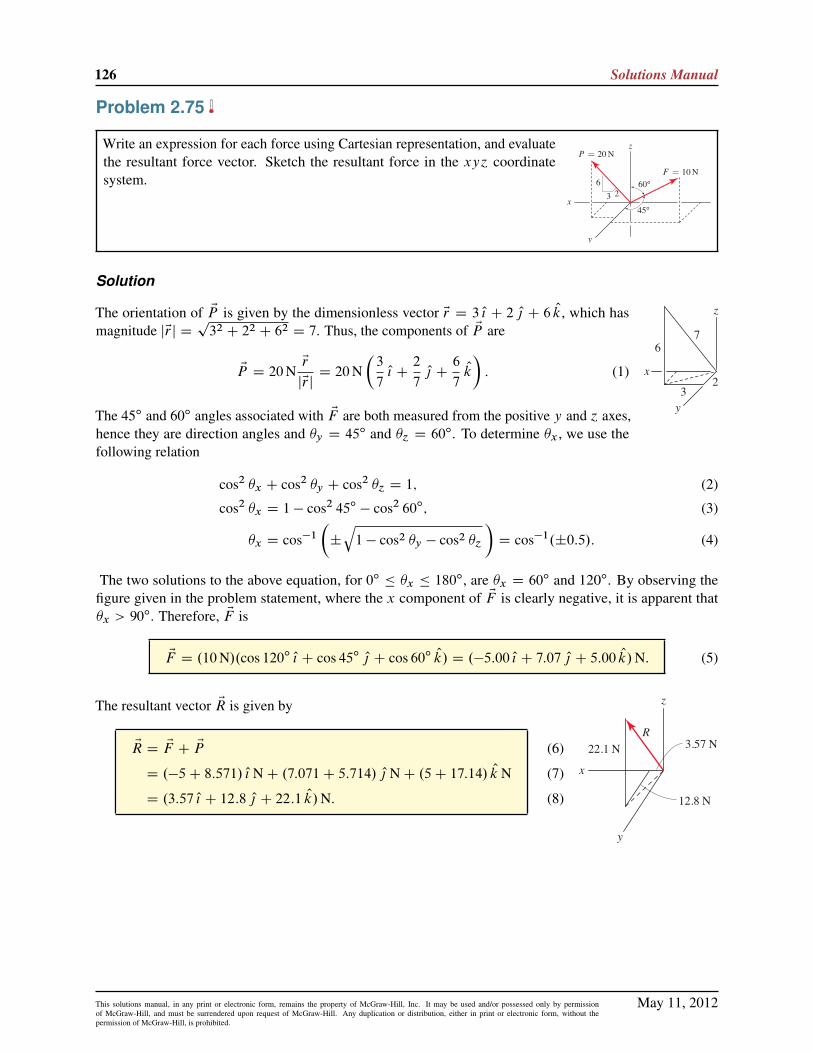
126 Solutions Manual
Problem 2.75
Write an expression for each force using Cartesian representation, and evaluatethe resultant force vector. Sketch the resultant force in the xy´ coordinatesystem.
Solution
The orientation of EP is given by the dimensionless vector Er D 3 O{ C 2 O| C 6 Ok, which hasmagnitude jEr j D
p32 C 22 C 62 D 7. Thus, the components of EP are
EP D 20NEr
jEr jD 20N
�3
7O{ C
2
7O| C
6
7Ok
�: (1)
The 45ı and 60ı angles associated with EF are both measured from the positive y and ´ axes,hence they are direction angles and �y D 45ı and �´ D 60ı. To determine �x , we use thefollowing relation
cos2 �x C cos2 �y C cos2 �´ D 1; (2)
cos2 �x D 1 � cos2 45ı � cos2 60ı; (3)
�x D cos�1
�˙
q1 � cos2 �y � cos2 �´
�D cos�1.˙0:5/: (4)
The two solutions to the above equation, for 0ı � �x � 180ı, are �x D 60ı and 120ı. By observing the
figure given in the problem statement, where the x component of EF is clearly negative, it is apparent that�x > 90
ı. Therefore, EF is
EF D .10N/.cos 120ı O{ C cos 45ı O| C cos 60ı Ok/ D .�5:00 O{ C 7:07 O| C 5:00 Ok/N: (5)
The resultant vector ER is given by
ER D EF C EP
D .�5C 8:571/ O{ NC .7:071C 5:714/ O| NC .5C 17:14/ Ok N
D .3:57 O{ C 12:8 O| C 22:1 Ok/N:
(6)
(7)
(8)
May 11, 2012This solutions manual, in any print or electronic form, remains the property of McGraw-Hill, Inc. It may be used and/or possessed only by permissionof McGraw-Hill, and must be surrendered upon request of McGraw-Hill. Any duplication or distribution, either in print or electronic form, without thepermission of McGraw-Hill, is prohibited.

Statics 2e 127
Problem 2.76
Write an expression for each force using Cartesian representation, and evaluatethe resultant force vector. Sketch the resultant force in the xy´ coordinatesystem.
Solution
The orientation of EQ is given by the dimensionless vector Er D �2 O{ C 2 O| C 1 Ok, which has magnitudejEr j D
p.�2/2 C 22 C 12 D 3. Thus, the components of EQ are
EQ D 4 kNEr
jEr jD 4 kN
��2
3O{ C
2
3O| C
1
3Ok
�; (1)
EQ D��2:667 O{ C 2:667 O| C 1:333 Ok
�kN: (2)
Using the sketch to the right, the projections of EP in the ´ and a directions are
P´ D .2 kN/ cos 50ı D 1:286 kN; (3)
Pa D .2 kN/ sin 50ı D 1:532 kN (4)
The component Pa may then be resolved into x and y components as follows
Px D �Pa cos 30ı D .�1:532 kN/ cos 30ı D �1:327 kN; (5)
Py D Pa sin 30ı D .1:532 kN/ sin 30ı D 0:7660 kN; (6)
such that
EP D��1:327 O{ C 0:7660 O| C 1:286 Ok
�kN: (7)
The angles reported for EF in the problem statement are measured from the positive coordinate directions, sothey are direction angles, and we may immediately write
EF D .3 kN/.cos 45ı O{ C cos 60ı O| C cos 60ı Ok/ D .2:121 O{ C 1:500 O| C 1:500 Ok/ kN: (8)
The resultant vector ER is given by
ER D EF C EP C EQ (9)
D .2:121 � 1:327 � 2:667/ O{ kN
C .1:500C 0:7660C 2:667/ O| kN (10)
C .1:500C 1:286C 1:333/ Ok kN:
ER D .�1:87 O{ C 4:93 O| C 4:12 Ok/ kN: (11)
May 11, 2012This solutions manual, in any print or electronic form, remains the property of McGraw-Hill, Inc. It may be used and/or possessed only by permissionof McGraw-Hill, and must be surrendered upon request of McGraw-Hill. Any duplication or distribution, either in print or electronic form, without thepermission of McGraw-Hill, is prohibited.

128 Solutions Manual
Problem 2.77
Write an expression for each force using Cartesian representation, and evaluatethe resultant force vector. Sketch the resultant force in the xy´ coordinatesystem.
Solution
The vectors ErOA and ErBO are given by
ErOA D .2 O{ � 6 O| � 3 Ok/ in.; ErBO D .�2 O{ C 6 O| � 9 Ok/ in.; (1)
and the unit vectors in the directions of these position vectors are
OuOA D.2 O{ � 6 O| � 3 Ok/ in.p22 C .�6/2 C .�3/2 in.
D 0:2857 O{ � 0:8571 O| � 0:4286 Ok; (2)
OuBO D.�2 O{ C 6 O| � 9 Ok/ in.p.�2/2 C 62 C .�9/2 in.
D �0:1818 O{ C 0:5455 O| � 0:8182 Ok: (3)
Therefore, the vectors EP and EQ are given by
EP D .2 lb/ OuOA D .0:571 O{ � 1:71 O| � 0:857 Ok/ lb;
EQ D .3 lb/ OuBO D .�0:545 O{ C 1:64 O| � 2:45 Ok/ lb:
(4)
(5)
Using the sketch to the right, the components of EF in the ´ and a directions are
F´ D .5 lb/ sin 45ı D 3:536 lb Fa D .5 lb/ cos 45ı D 3:536 lb: (6)
The component Fa may then be resolved into x and y components as follows
Fx D .3:536 lb/ cos 30ı D 3:062 lb; Fy D .3:536 lb/ sin 30ı D 1:768 lb: (7)
The Cartesian representation for EF is
EF D .3:06 O{ C 1:77 O| C 3:54 Ok/ lb: (8)
z
y
x
3.09 lb
1.69 lb0.224 lb
The resultant vector ER is given by
ER D EF C EP C EQ
D .3:062C 0:5714 � 0:5455/ O{ lb
C .1:768 � 1:714C 1:636/ O| lb
C .3:536 � 0:8572 � 2:455/ Ok lb
D .3:09 O{ C 1:69 O| C 0:224 Ok/ lb:
(9)
(10)
(11)
May 11, 2012This solutions manual, in any print or electronic form, remains the property of McGraw-Hill, Inc. It may be used and/or possessed only by permissionof McGraw-Hill, and must be surrendered upon request of McGraw-Hill. Any duplication or distribution, either in print or electronic form, without thepermission of McGraw-Hill, is prohibited.

Statics 2e 129
Problem 2.78
For each vector, find the direction angles and write an expression for the vectorusing Cartesian representation. Evaluate the sum of the two vectors, and reportthe direction angles for the resultant. Also, sketch the resultant in the xy´coordinate system.
Solution
For force EF , the direction angles �x D 60ı and �´ D 50ı are obtained from the figure in the problemstatement, and the remaining direction angle is obtained from
�y D cos�1.˙p1 � cos2 �x � cos2 �´/ D cos�1.˙0:5804/ D 54:52ı; 125:5ı: (1)
By examining the orientation of EF in the figure for the problem statement, the y component of EF is clearlynegative, and hence the correct y direction angle is �y D 125:5
ı. Thus, for force EF ,
�x D 60ı; �y D 125:5
ı; �´ D 50ıI EF D .25N/.cos 60ı O{ C cos 125:5ı O| C cos 50ı Ok/
D .12:5 O{ � 14:5 O| C 16:1 Ok/N:
(2)
(3)
For force EP , the direction angles �y D 45ı and �´ D 75ı are obtained from the figure in the problemstatement, and the remaining direction angle is obtained from
�x D cos�1.˙
q1 � cos2 �y � cos2 �´/ D cos�1.˙0:6580/ D 48:84ı; 131:2ı: (4)
By examining the orientation of EP in the figure for the problem statement, the x component of EP is clearlypositive, and hence the correct x direction angle is �x D 48:84
ı. Thus, for force EP ,
�x D 48:84ı; �y D 45
ı; �´ D 75ıI EP D .75N/.cos 48:84ı O{ C cos 45ı O| C cos 75ı Ok/
D .49:4 O{ C 53:0 O| C 19:4 Ok/N:
(5)
(6)
The sum of these vectors is given by
ER D EF C EP D .61:9 O{ C 38:5 O| C 35:5 Ok/N; (7)
the magnitude is R Dp.61:85N/2 C .38:52N/2 C .35:48N/2 D 81:05N, and the direction angles are:
cos �x D Rx=R D 61:85N=81:05N D 0:7632
) �x D cos�1.0:7632/ D 40:3ı;
cos �y D Ry=R D 38:52N=81:05N D 0:4753
) �y D cos�1.0:4753/ D 61:6ı;
cos �´ D R´=R D 35:48N=81:05N D 0:4378
) �´ D cos�1.0:4378/ D 64:0ı:
(8)
(9)
(10)
(11)
(12)
(13)
May 11, 2012This solutions manual, in any print or electronic form, remains the property of McGraw-Hill, Inc. It may be used and/or possessed only by permissionof McGraw-Hill, and must be surrendered upon request of McGraw-Hill. Any duplication or distribution, either in print or electronic form, without thepermission of McGraw-Hill, is prohibited.

130 Solutions Manual
Problem 2.79
For each vector, find the direction angles and write an expression for the vectorusing Cartesian representation. Evaluate the sum of the two vectors, and reportthe direction angles for the resultant. Also, sketch the resultant in the xy´coordinate system.
Solution
From the figure in the problem statement, position vectors Er and Es may be immediately written as
Er D .�10 O{ C 15 O| C 6 Ok/ in. and Es D .sx O{ C 12 O| C 9 Ok/ in.; (1)
where sx denotes the x component of Es. Knowing that the magnitude of Es is s D 25 in:, the value of sx maybe determined using
s2D .25 in:/2 D s2
x C .12 in:/2 C .9 in:/2 ) x D ˙20 in:: (2)
The positive solution for x is selected so that Es has the orientation shown in the problem statement. Hence,the vector representation of Es is
Es D .20 O{ C 12 O| C 9 Ok/ in. (3)
The resultant of Er and Es is given by
ER D Es C Er D�.20 � 10/ O{ C .12C 15/ O| C .9C 6/ Ok
�in. D
�10 O{ C 27 O| C 15 Ok
�in.: (4)
The magnitude of ER is given by R Dp102 C 272 C 152 in. D 32:47 in:, and
the direction angles for ER are obtained using
cos �x D Rx=R D 10 in:=32:47 in: D 0:3080
) �x D cos�1.0:3080/ D 72:1ı;
cos �y D Ry=R D 27 in:=32:47 in: D 0:8317
) �y D cos�1.0:8317/ D 33:7ı;
cos �´ D R´=R D 15 in:=32:47 in: D 0:4620
) �´ D cos�1.0:4620/ D 62:5ı:
(5)
(6)
(7)
(8)
(9)
(10)
May 11, 2012This solutions manual, in any print or electronic form, remains the property of McGraw-Hill, Inc. It may be used and/or possessed only by permissionof McGraw-Hill, and must be surrendered upon request of McGraw-Hill. Any duplication or distribution, either in print or electronic form, without thepermission of McGraw-Hill, is prohibited.

Statics 2e 131
Problem 2.80
The Space Shuttle uses radar to determine the magnitudes and direction cosinesof position vectors to satellites A and B as
for ErOAW jErOAj D 2 km; cos �x D 0:768; cos �y D �0:384; cos �´ D 0:512;
for ErOBW jErOB j D 4 km; cos �x D 0:743; cos �y D 0:557; cos �´ D �0:371:
Determine the distance between the satellites.
Solution
Begin by writing expressions for the position vectors ErOA and ErOB as
ErOA D .2 km/.0:768 O{ � 0:384 O| C 0:512 Ok/ D .1:536 O{ � 0:7680 O| C 1:024 Ok/ km; (1)
ErOB D .4 km/.0:743 O{ C 0:557 O| � 0:371 Ok/ D .2:972 O{ C 2:228 O| � 1:484 Ok/ km: (2)
The position vector from A to B is given by ErAB , and it may be expressed as
ErAB D ErAO C ErOB (3)
D �ErOA C ErOB (4)
D�.�1:536C 2:972/ O{ C .0:7680C 2:228/ O| C .�1:024 � 1:484/ Ok
�km (5)
D .1:436 O{ C 2:996 O| � 2:508 Ok/ km: (6)
The magnitude of ErAB is the distance between the satellites. Thus
rAB D
q.1:436 km/2 C .2:996 km/2 C .�2:508 km/2 D 4:16 km: (7)
May 11, 2012This solutions manual, in any print or electronic form, remains the property of McGraw-Hill, Inc. It may be used and/or possessed only by permissionof McGraw-Hill, and must be surrendered upon request of McGraw-Hill. Any duplication or distribution, either in print or electronic form, without thepermission of McGraw-Hill, is prohibited.

132 Solutions Manual
Problem 2.81
A cube of material with 1mm edge lengths is examined by a scanning electronmicroscope, and a small inclusion (i.e., a cavity) is found at point P . It isdetermined that the direction cosines for a vector from points A to P arecos �x D �0:485, and cos �y D 0:485, and cos �´ D �0:728; and the directioncosines for a vector from pointsB to P are cos �x D �0:667, cos �y D �0:667,and cos �´ D 0:333. Determine the coordinates of point P .
Solution
The distance between points A and P and points B and P is rAP and rBP , respectively. If ErBA is the positionvector from point B to point A, given by
ErBA D .�1 O| C 1 Ok/mm; (1)
then we may write
ErBA C ErAP D ErBP (2)
.�1 O| C 1 Ok/mmC rAP .�0:485 O{ C 0:485 O| � 0:728 Ok/ D rBP .�0:667 O{ � 0:667 O| C 0:333 Ok/: (3)
Equation (3) may be rewritten as
.�0:485 rAP C 0:667 rBP / O{ C .�1mmC 0:485 rAP C 0:667 rBP / O|
C .1mm � 0:728 rAP � 0:333 rBP / Ok D E0: (4)
For Eq. (4) to be satisfied, each term multiplying O{, O| , and Ok must be zero. Furthermore, Eq. (4) contains onlytwo unknowns, thus we use the equations corresponding to the O{ and O| terms to solve for rAP and rBP asfollows
�0:485 rAP C 0:667 rBP D 0 ) rAP D 1:375 rBP ; (5)
�1mmC 0:485.1:375 rBP /C 0:667 rBP D 0 ) rBP D 0:7496mm: (6)
Note that the above solutions for rAP and rBP also satisfy the equation corresponding to the Ok term.To determine the coordinates of point P , we consider the vector ErOP , which may be written as
ErOP D ErOB C ErBP : (7)
In Eq. (7), ErOP D xP O{ C yP O| C ´POk, the vector ErBP is known from the direction cosines given in the
problem statement and Eq. (6), and ErOB D .1 O{ C 1 O|/mm. Thus, Eq. (7) becomes
xP O{ C yP O| C ´POk D .1 O{ C 1 O|/mmC .0:7496mm/.�0:667 O{ � 0:667 O| C 0:333 Ok/mm (8)
D�0:500 O{ C 0:500 O| C 0:250 Ok
�: (9)
Therefore, the coordinates of point P are
.0:500; 0:500; 0:250/mm: (10)
May 11, 2012This solutions manual, in any print or electronic form, remains the property of McGraw-Hill, Inc. It may be used and/or possessed only by permissionof McGraw-Hill, and must be surrendered upon request of McGraw-Hill. Any duplication or distribution, either in print or electronic form, without thepermission of McGraw-Hill, is prohibited.

Statics 2e 133
Problem 2.82
A theodolite is an instrument that measures horizontal and vertical angularorientations of a line of sight. The line of sight may be established optically,or by laser, and many forms of theodolite are used in surveying, construction,astronomy, and manufacturing. A simple optical theodolite is shown. Afterthe instrument is aligned so that its base is in a horizontal plane and a desiredreference direction is selected (such as perhaps north in the case of a surveyinginstrument), the telescopic sight is used to establish a line of sight, and thenhorizontal and vertical angles �h and �v are measured.
(a) If �h and �v are known, derive an expression that gives the directionangles �x , �y , and �´ for the line of sight.
(b) If �h D 30ı and �v D 60
ı, use your answer to Part (a) to determine �x ,�y , and �´.
Solution
Part (a) Let Er be a vector along the line of sight of the theodolite, and let themagnitude of this vector be r . Using angle �v, this vector may be resolved into ´direction and a direction components, as shown in the figure to the right, as
r´ D r sin �v and ra D r cos �v: (1)
The component ra may then be resolved into x and y components as
rx D ra sin �h and ry D ra cos �h: (2)
Combining Eqs. (1) and (2) allows an expression for Er to be written as
Er D r�
sin �h cos �v O{ C cos �h cos �v O| C sin �vOk�: (3)
In terms of direction angles �x , �y , and �´, the vector Er may alternatively be written as
Er D cos �x O{ C cos �y O| C cos �´Ok: (4)
For Eqs. (3) and (4) to agree, the direction angles are
cos �x D sin �h cos �v ) �x D ˙ cos�1.sin �h cos �v/;
cos �y D cos �h cos �v ) �y D ˙ cos�1.cos �h cos �v/;
cos �´ D sin �v ) �´ D ˙ cos�1.sin �v/ D ˙.90ı� �v/:
(5)
(6)
(7)
Part (b) With �h D 30ı and �v D 60
ı, Eqs. (5)–(7) provide the direction angles for the line of sight as
�x D cos�1.sin 30ı cos 60ı/ D 75:5ı;
�y D cos�1.cos 30ı cos 60ı/ D 64:3ı;
�´ D 90ı� 60ı D 30ı:
(8)
(9)
(10)
May 11, 2012This solutions manual, in any print or electronic form, remains the property of McGraw-Hill, Inc. It may be used and/or possessed only by permissionof McGraw-Hill, and must be surrendered upon request of McGraw-Hill. Any duplication or distribution, either in print or electronic form, without thepermission of McGraw-Hill, is prohibited.

134 Solutions Manual
Problem 2.83
With direction angles, general practice is to use values of �x , �y , and �´ between 0ı and 180ı, and thisis sufficient to characterize the orientation of any vector in three dimensions. When direction angles aremeasured in this way, the sum of any two direction angles is always 90ı or greater. Offer an argument thatshows this statement is true.
Solution
We are asked to show that the quantities �x C �y , �x C �´, and �y C �´ are all equalto or greater than 90ı. Begin by considering a vector Ev that lies in the xy plane, in thequadrant shown at the right. For this vector, �´ D 90
ı, and it necessarily follows that�x C �y must then equal 90ı, i.e.,
�´ D 90ı) �x C �y D 90
ı: (1)
Note that if the vector lies in any other quadrant of the xy plane, then Eq. (1) becomes �x C �y > 90ı; hence
the quadrant shown gives rise to the most conservative case for our purposes. Now, if we add a ´ componentto this vector while keeping the x and y components fixed, it follows that �x C �y > 90
ı. Therefore, for anyvector constructed by following this approach,
�x C �y � 90ı: (2)
Note that as we add a ´ component in the manner described, �´ will decrease. Therefore, we cannot yet sayanything about the quantities �x C �´ or �y C �´.
Now, repeat the above argument starting with a vector having only y and ´ components, and then add thex component. This leads to the conclusion that for any vector constructed in this manner, its direction anglessatisfy
�y C �´ � 90ı: (3)
Repeating this same line of reasoning once more, starting with a vector having x and ´ components, andthen add the y component. This leads to the conclusion that for any vector constructed in this manner, itsdirection angles satisfy
�x C �´ � 90ı: (4)
Since any vector may be constructed by following any of these approaches, it is true that
�x C �y � 90ı; �y C �´ � 90
ı; and �x C �´ � 90ı: (5)
May 11, 2012This solutions manual, in any print or electronic form, remains the property of McGraw-Hill, Inc. It may be used and/or possessed only by permissionof McGraw-Hill, and must be surrendered upon request of McGraw-Hill. Any duplication or distribution, either in print or electronic form, without thepermission of McGraw-Hill, is prohibited.

Statics 2e 135
Problem 2.84
If the direction cosines for the satellite antenna shown are to be cos �x D 0:286,cos �y D 0:429, and cos �´ D 0:857, determine the values of angles �h and �v .
Solution
Let Ou be a unit vector that points in the direction of the antenna. Using the directioncosines given in the problem statement, this vector may be written as
Ou D 0:286 O{ C 0:429 O| C 0:857 Ok: (1)
The figure to the right shows the components of Ou. By inspection of this figure, observethat
tan �h Dx component of Ouy component of Ou
Dcos �x
cos �yD0:286
0:429; (2)
sin �v D´ component of Ou
1D
cos �´
1D0:857
1: (3)
Hence,
�h D tan�1 0:286
0:429D 33:7ı; �v D sin�1 0:857
1D 59:0ı: (4)
Remark These answers may be checked using the results of Prob. 2.82. Before carrying out this check,we must first verify that �h and �v are defined with respect to the x, y, and ´ axis in the same way in thisproblem and in Prob. 2.82, and indeed this is the case. Then, substituting the values of �x , �y , �´, �h, and �v
into the relations from Prob. 2.82 shows that all of the following expressions are satisfied
cos �x D sin �h cos �v D 0:2859; (5)
cos �y D cos �h cos �v D 0:4288; (6)
cos �´ D sin �v D 0:8570: (7)
May 11, 2012This solutions manual, in any print or electronic form, remains the property of McGraw-Hill, Inc. It may be used and/or possessed only by permissionof McGraw-Hill, and must be surrendered upon request of McGraw-Hill. Any duplication or distribution, either in print or electronic form, without thepermission of McGraw-Hill, is prohibited.

136 Solutions Manual
Problem 2.85
Using a theodolite with a laser rangefinder, a researcher at point A locates a pairof rare birds nesting at point B and determines the direction angles �x D 53
ı,�y D 38
ı, and �´ D 81ı and distance 242 m for a position vector from point A
to B . For subsequent observations, the researcher would like to use position C ,and thus while at point A, she also measures the direction angles �x D 142
ı,�y D 63
ı, and �´ D 65ı and distance 309 m for a position vector from point A
to C . For observation from point C , determine the direction angles and distanceto the nest at B .
Solution
Our objective is to determine the position vector ErCB , and we may accomplish this by using vector additionas follows
ErCB D ErCA C ErAB (1)
D �ErAC C ErAB (2)
D �.309m/.cos 142ı O{ C cos 63ı O| C cos 65ı Ok/
C.242m/.cos 53ı O{ C cos 38ı O| C cos 81ı Ok/ (3)
D .389:1 O{ C 50:42 O| � 92:73 Ok/m: (4)
The magnitude of ErCB , and hence the distance from point C to the nest at point B , is
rCB D
q.389:1m/2 C .50:42m/2 C .�92:73m/2 D 403:2m: (5)
The direction angles for ErCB are
cos �x D.rCB/x
rCBD389:1m403:2m
D 0:9651 ) �x D cos�1.0:9651/ D 15:18ı;
cos �y D.rCB/y
rCBD50:42m403:2m
D 0:1250 ) �y D cos�1.0:1250/ D 82:82ı;
cos �´ D.rCB/´
rCBD�92:73m403:2m
D �0:2300 ) �´ D cos�1.�0:2300/ D 103:3ı:
(6)
(7)
(8)
Note that the direction angles in the problem statement are accurate to only two digits, hence the directionangles given in Eqs. (6)–(8) should be interpreted as being of similar accuracy.
May 11, 2012This solutions manual, in any print or electronic form, remains the property of McGraw-Hill, Inc. It may be used and/or possessed only by permissionof McGraw-Hill, and must be surrendered upon request of McGraw-Hill. Any duplication or distribution, either in print or electronic form, without thepermission of McGraw-Hill, is prohibited.

Statics 2e 137
Problem 2.86
A robot maneuvers itself by using a laser guidance systemwhere the positions of reflective targets, such as at points Band C , are known. By scanning the room with a laser thatemanates from point A, and sensing the reflections from targetsB and C , the robot may compute the direction cosines ofposition vectors as given below. The locations of other points,such as point D at the base of the ramp, are also known, butsuch locations do not have reflective targets. Determine theposition vector from points A to D so that the robot may movefrom its current position to the base of the ramp at point D.
for ErABW cos �x D �0:4212; cos �y D �0:9025; cos �´ D 0:0902;
for ErAC W cos �x D 0:2676; cos �y D �0:9635; cos �´ D 0:
Solution
With the direction cosines provided in the problem statement, the following position vectors may be written
ErAB D rAB.�0:4212 O{ � 0:9025 O| C 0:0902 Ok/; (1)
ErAC D rAC .0:2676 O{ � 0:9635 O|/: (2)
With the coordinates of points B and C provided in the problem statement, the following position vector maybe written
ErBC D�.240 � 0/ O{ C .�60 � 0/ O| C .90 � 120/ Ok
�cm (3)
D .240 O{ � 60 O| � 30 Ok/ cm: (4)
Using vector addition, as shown below, we may write
ErAC D ErAB C ErBC (5)
rAC .0:2676 O{ � 0:9635 O|/D rAB.�0:4212 O{ � 0:9025 O| C 0:0902 Ok/
C .240 O{ � 60 O| � 30 Ok/ cm: (6)
May 11, 2012This solutions manual, in any print or electronic form, remains the property of McGraw-Hill, Inc. It may be used and/or possessed only by permissionof McGraw-Hill, and must be surrendered upon request of McGraw-Hill. Any duplication or distribution, either in print or electronic form, without thepermission of McGraw-Hill, is prohibited.

138 Solutions Manual
Equating the x, y, and ´ components of the above vector expression provides
rAC .0:2676/D rAB.�0:4212/C 240 cm; (7)
rAC .�0:9635/D rAB.�0:9025/ � 60 cm; (8)
0D rAB.0:0902/ � 30 cm: (9)
Equation (9) may be immediately solved to obtain
rAB D30 cm0:0902
D 332:6 cm: (10)
Then, either of Eqs. (7) or (8) may be used to determine rAC , as follows. If Eq. (7) is used, then
rAC DrAB.�0:4212/C 240 cm
0:2676D 373:4 cm; (11)
and if Eq. (8) is used instead, then
rAC DrAB.�0:9025/ � 60 cm
�0:9635D 373:8 cm: (12)
The differences in the results in Eqs. (11) and (12) is small and is due to the small error in using four digitsfor the direction cosines in the problem statement. In the remainder of this solution, we will not need ErAC ,although if this were to be used, then it would probably be best to use an average of Eqs. (11) and (12).
Using vector addition, as shown below, we may write
ErAD D ErAB C ErBD: (13)
With the coordinates of points B and D provided in the problem statement, we have
ErBD D�.60 � 0/O{ C .150 � 0/ O| C .0 � 120 Ok/
�cm (14)
D .60 O{ C 150 O| � 120 Ok/ cm: (15)
Hence,
ErAD D 332:6 cm.�0:4212 O{ � 0:9025 O| C 0:0902 Ok/
C .60 O{ C 150 O| � 120 Ok/ cm (16)
ErAD D .�80:09 O{ � 150:2 O| � 90:00 Ok/cm: (17)
May 11, 2012This solutions manual, in any print or electronic form, remains the property of McGraw-Hill, Inc. It may be used and/or possessed only by permissionof McGraw-Hill, and must be surrendered upon request of McGraw-Hill. Any duplication or distribution, either in print or electronic form, without thepermission of McGraw-Hill, is prohibited.

Statics 2e 139
Problem 2.87
A mountain climbing team establishes base camps at points A and B , and thenext camp is to be at point C . Camps A and B have elevations of 11;500 ft and16;000 ft above sea level, respectively. With an optical telescope, the directionangles for position vectors from A to B , and B to C , and A to C are determinedas follows:
for ErABW �x D 34:3ı; �y D 63:2
ı; �´ D 70:2ı;
for ErBC W �x D 104:7ı; �y D 27:3
ı; �´ D 67:6ı;
for ErAC W �x D 59:1ı; �y D 42:0
ı; �´ D 64:6ı:
Determine the elevation above sea level of camp C .
Solution
With the direction angles provided in the problem statement, the following position vectors may be written
ErAB D rAB.cos 34:3ıO{ C cos 63:2ı O| C cos 70:2ı Ok/; (1)
ErBC D rBC .cos 104:7ıO{ C cos 27:3ı O| C cos 67:6ı Ok/; (2)
ErAC D rAC .cos 59:1ıO{ C cos 42:0ı O| C cos 64:6ı Ok/: (3)
Using the elevations of points A and B given in the problem statement, the difference in elevation betweenpoints B and A is 16,000 ft � 11,500 ftD 4,500 ft. Hence, the ´ component of ErAB in Eq. (1) must be 4,500 ft,which provides
rAB cos 70:2ı D 4,500 ft) rAB D 13,285 ft: (4)
Using vector addition, as shown at the right, we may write
ErAC D ErAB C ErBC (5)
D 13,285 ft .cos 34:3ı O{ C cos 63:2 O| C cos 70:2 Ok/
C rBC .cos 104:7ı O{ C cos 27:3ı O| C cos 67:6ı Ok/: (6)
Equations (3) and (6) are equal, and we equate the x, y, and ´ components of these to obtain the followingequations
rAC cos 59:1ı D .13;285 ft/ cos 34:3ı C rBC cos 104:7ı; (7)
rAC cos 42:0ı D .13;285 ft/ cos 63:2ı C rBC cos 27:3ı; (8)
rAC cos 64:6ı D .13;285 ft/ cos 70:2ı C rBC cos 67:6ı: (9)
As explained in the Closer Look discussion at the end of Example 2.11 on p. 73, only two of Eqs. (7)–(9)are independent, and any two of the three may be used to determine the unknowns rAC and rBC , with thefollowing results:
Using Eqs. .7/ and .8/ ) rAC D 17;478 ft; and rBC D 7;876 ft; (10)
Using Eqs. .8/ and .9/ ) rAC D 17;519 ft; and rBC D 7;910 ft; (11)
Using Eqs. .7/ and .9/ ) rAC D 17;482 ft; and rBC D 7;869 ft: (12)
May 11, 2012This solutions manual, in any print or electronic form, remains the property of McGraw-Hill, Inc. It may be used and/or possessed only by permissionof McGraw-Hill, and must be surrendered upon request of McGraw-Hill. Any duplication or distribution, either in print or electronic form, without thepermission of McGraw-Hill, is prohibited.

140 Solutions Manual
The small differences in these results are due to the small inaccuracy in the direction angles given in theproblem statement. Thus, we will use the approx. values
rAC D 17;500 ft and rBC D 7;890 ft: (13)
The elevation of point C relative to point A is given by the ´ component of ErAC . Hence, the elevation abovesea level of point C is approximately
hD 11;500 ftC 17;500 ft cos 64:6ı (14)
D 19,000 ft. (15)
May 11, 2012This solutions manual, in any print or electronic form, remains the property of McGraw-Hill, Inc. It may be used and/or possessed only by permissionof McGraw-Hill, and must be surrendered upon request of McGraw-Hill. Any duplication or distribution, either in print or electronic form, without thepermission of McGraw-Hill, is prohibited.

Statics 2e 141
Problem 2.88
BarsAC andDG are straight and parallel to the x and y axes, respectively. BEis a cable whose tensile force is 100 lb. For the dimensions given, determineexpressions for the force the cable exerts on B and the force the cable exerts onE using Cartesian vector representation. x D 4 in: and y D 7 in.
Solution
Begin by writing an expression for the vector ErBE , which is the position vector pointing from B to E
ErBE D .�4 O{ C 7 O| � 4 Ok/ in.; jErBE j D
q.�4/2 C .7/2 C .�4/2 in. D 9 in: (1)
Since the force in cable BE is tensile, the force that this cable applies to the collar at B is directed from B
toward E, hence
EFBE D .100 lb/ErBE
jErBE jD .100 lb/
�4 O{ C 7 O| � 4 Ok
9
D .�44:4 O{ C 77:8 O| � 44:4 Ok/ lb: (2)
The force that cable BE applies to the collar at E is directed from E toward B , hence
EFEB D �EFBE
D .44:4 O{ � 77:8 O| C 44:4 Ok/ lb: (3)
May 11, 2012This solutions manual, in any print or electronic form, remains the property of McGraw-Hill, Inc. It may be used and/or possessed only by permissionof McGraw-Hill, and must be surrendered upon request of McGraw-Hill. Any duplication or distribution, either in print or electronic form, without thepermission of McGraw-Hill, is prohibited.

142 Solutions Manual
Problem 2.89
BarsAC andDG are straight and parallel to the x and y axes, respectively. BEis a cable whose tensile force is 100 lb. For the dimensions given, determineexpressions for the force the cable exerts on B and the force the cable exerts onE using Cartesian vector representation. x D 6 in: and y D 12 in.
Solution
Begin by writing an expression for the vector ErBE , which is the position vector pointing from B to E
ErBE D .�6 O{ C 12 O| � 4 Ok/ in.; jErBE j D
q.�6/2 C .12/2 C .�4/2 in. D 14 in: (1)
Since the force in cable BE is tensile, the force that this cable applies to the collar at B is directed from B
toward E, hence
EFBE D .100 lb/ErBE
jErBE jD .100 lb/
�6 O{ C 12 O| � 4 Ok
14
D .�42:9 O{ C 85:7 O| � 28:6 Ok/ lb: (2)
The force that cable BE applies to the collar at E is directed from E toward B , hence
EFEB D �EFBE
D .42:9 O{ � 85:7 O| C 28:6 Ok/ lb: (3)
May 11, 2012This solutions manual, in any print or electronic form, remains the property of McGraw-Hill, Inc. It may be used and/or possessed only by permissionof McGraw-Hill, and must be surrendered upon request of McGraw-Hill. Any duplication or distribution, either in print or electronic form, without thepermission of McGraw-Hill, is prohibited.

Statics 2e 143
Problem 2.90
A crane consists of a quarter-circular bar that lies in a plane parallel to the x´plane with a low-friction collar at point B that may slide on the bar. The forcessupported by cables AB and BC are 30 lb and 1500 lb, respectively, and thecoordinates of point A are given in the figure. For the value of angle ˛ givenbelow, determine expressions for the forces the two cables apply to the collar atpoint B . ˛ D 0ı.
Solution
The coordinates of point A are given in the problem statement, and with ˛ D 0ı, the coordinates of point Bare (0, 10, 5) ft. Hence, the position vector from point B to point A is
ErBA D .8 O{ � 5:5 O| � 3 Ok/ ft: (1)
The force that cable AB applies to the collar at point B is
EFBA D 30 lbErBA
rBAD 30 lb
8 O{ � 5:5 O| � 3 Ok
10:16(2)
D .23:62 O{ � 16:24 O| � 8:857 Ok/ lb: (3)
By inspection, the force that cable BC applies to the collar at point B is
EFBC D �1500 lb O| : (4)
May 11, 2012This solutions manual, in any print or electronic form, remains the property of McGraw-Hill, Inc. It may be used and/or possessed only by permissionof McGraw-Hill, and must be surrendered upon request of McGraw-Hill. Any duplication or distribution, either in print or electronic form, without thepermission of McGraw-Hill, is prohibited.

144 Solutions Manual
Problem 2.91
A crane consists of a quarter-circular bar that lies in a plane parallel to the x´plane with a low-friction collar at point B that may slide on the bar. The forcessupported by cables AB and BC are 30 lb and 1500 lb, respectively, and thecoordinates of point A are given in the figure. For the value of angle ˛ givenbelow, determine expressions for the forces the two cables apply to the collar atpoint B . ˛ D 30ı.
Solution
The coordinates of point A are given in the problem statement, and with ˛ D 30ı, the coordinates of point Bare .5 ft sin 30ı; 10 ft; 5 ft cos 30ı/. Hence, the position vector from point B to point A is
ErBA D .5:5 O{ � 5:5 O| � 2:330 Ok/ ft: (1)
The force that cable AB applies to the collar at point B is
EFBA D 30 lbErBA
rBAD 30 lb
5:5 O{ � 5:5 O| � 2:330 Ok
8:120(2)
D .20:32 O{ � 20:32 O| � 8:609 Ok/ lb: (3)
By inspection, the force that cable BC applies to the collar at point B is
EFBC D �1500 lb O| : (4)
May 11, 2012This solutions manual, in any print or electronic form, remains the property of McGraw-Hill, Inc. It may be used and/or possessed only by permissionof McGraw-Hill, and must be surrendered upon request of McGraw-Hill. Any duplication or distribution, either in print or electronic form, without thepermission of McGraw-Hill, is prohibited.

Statics 2e 145
Problem 2.92
A crane consists of a quarter-circular bar that lies in a plane parallel to the x´plane with a low-friction collar at point B that may slide on the bar. The forcessupported by cables AB and BC are 30 lb and 1500 lb, respectively, and thecoordinates of point A are given in the figure. For the value of angle ˛ givenbelow, determine expressions for the forces the two cables apply to the collar atpoint B . ˛ D 60ı.
Solution
The coordinates of point A are given in the problem statement, and with ˛ D 60ı, the coordinates of point Bare (5 ft sin 60ı, 10 ft, 5 ft cos 60ı). Hence, the position vector from point B to point A is
ErBA D .3:670 O{ � 5:5 O| � 0:5 Ok/ ft: (1)
The force that cable AB applies to the collar at point B is
EFBA D 30 lbErBA
rBAD 30 lb
3:670 O{ � 5:5 O| � 0:5 Ok
6:631(2)
D .16:60 O{ � 24:88 O| � 2:262 Ok/ lb: (3)
By inspection, the force that cable BC applies to the collar at point B is
EFBC D �1500 lb O| : (4)
May 11, 2012This solutions manual, in any print or electronic form, remains the property of McGraw-Hill, Inc. It may be used and/or possessed only by permissionof McGraw-Hill, and must be surrendered upon request of McGraw-Hill. Any duplication or distribution, either in print or electronic form, without thepermission of McGraw-Hill, is prohibited.

146 Solutions Manual
Problem 2.93
A crane consists of a quarter-circular bar that lies in a plane parallel to the x´plane with a low-friction collar at point B that may slide on the bar. The forcessupported by cables AB and BC are 30 lb and 1500 lb, respectively, and thecoordinates of point A are given in the figure. For the value of angle ˛ givenbelow, determine expressions for the forces the two cables apply to the collar atpoint B . General values of ˛ where 0ı � ˛ � 90ı.
Solution
The coordinates of point A are given in the problem statement and the coordinates of point B are (5 ft sin˛,10 ft, 5 ft cos˛). Hence, the position vector from point B to point A is
ErBA D�.8 � 5 sin˛/ O{ � 5:5 O| C .2 � 5 cos˛/ Ok
�ft; (1)
and the magnitude of ErBA is
rBA D
q.8 � 5 sin˛/2 C .�5:5/2 C .2 � 5 cos˛/2 ft. (2)
The force that cable AB applies to the collar at point B is
EFBA D 30 lbErBA
rBA(3)
D 30 lb.8 � 5 sin˛/ O{ � 5:5 O| C .2 � 5 cos˛/ Okp.8 � 5 sin˛/2 C .�5:5/2 C .2 � 5 cos˛/2
. (4)
By inspection, the force that cable BC applies to the collar at point B is
EFBC D �1500 lb O| : (5)
Remark: To help verify the accuracy of our result for EFBA, Eq. (4) may be used to verify the answers for theprevious three problems. For example:
If ˛ D 0ı, Eq. (4) givesEFBA D .23:62 O{ � 16:24 O| � 8:857 Ok/ lb; (6)
which agrees with the answer to Prob. 2.90.
If ˛ D 60ı, Eq. (4) gives
EFBA D .16:60 O{ � 24:88 O| � 2:262 Ok/ lb; (7)
which agrees with the answer to Prob. 2.92.
May 11, 2012This solutions manual, in any print or electronic form, remains the property of McGraw-Hill, Inc. It may be used and/or possessed only by permissionof McGraw-Hill, and must be surrendered upon request of McGraw-Hill. Any duplication or distribution, either in print or electronic form, without thepermission of McGraw-Hill, is prohibited.

Statics 2e 147
Problem 2.94
The structure consists of a quarter-circular rod AB with radius 150 mm thatis fixed in the xy plane. CD is a straight rod where D may be positioned atdifferent locations on the circular rod. GE is an elastic cord whose support atG lies in the y´ plane, and the bead at E may have different positions d . Forthe values of b, h, d , and ´ provided, determine the coordinates of E, and if theelastic cord supports a tensile force of 100 N, write a vector expression usingCartesian vector representation for the force EFEG the cord exerts on bead E.b D 4, h D 3, d D 260mm; and ´ D 240mm.
Solution
D
E
G
C
x
y
z
360 mm
260 mm150(4/5) = 120 mm
150 mm
120 mm
240 mm150 mm
150(3/5) = 90 mm
Let ErCD be the position vector from point C to point D. Usingthe figure to the right, this vector, its magnitude, and a unit vectorin this direction, are given by
ErCD D .120 O{ C 90 O| � 360 Ok/mm; (1)
rCD D
q1202 C 902 C .�360/2 mm D 390mm; (2)
OuCD D.120 O{ C 90 O| � 360 Ok/mm
390mmD 0:3077 O{ C 0:2308 O| � 0:9231 Ok; (3)
The position vector from C to E is
ErCE D .260mm/ OuCD D .260mm/.0:3077 O{ C 0:2308 O| � 0:9231 Ok/;
D .80 O{ C 60 O| � 240 Ok/mm: (4)
The coordinates of point E are easily obtained once vector ErOE has been determined, which can be accom-plished using
ErOE D ErOC C ErCE D .360 Ok/mmC .80 O{ C 60 O| � 240 Ok/mm (5)
D .80 O{ C 60 O| C 120 Ok/mm: (6)
Hence, the coordinates of point E are
.80; 60; 120/mm: (7)
Using the geometry provided in the problem statement, the vector pointing from C to G is given byErCG D .150 O| � 90 Ok/mm, and the vector ErEG can be obtained using
ErEG D ErEC C ErCG D �ErCE C ErCG (8)
D �.80 O{ C 60 O| � 240 Ok/mmC .150 O| � 120 Ok/mm (9)
D .�80 O{ C 90 O| C 120 Ok/mm: (10)
May 11, 2012This solutions manual, in any print or electronic form, remains the property of McGraw-Hill, Inc. It may be used and/or possessed only by permissionof McGraw-Hill, and must be surrendered upon request of McGraw-Hill. Any duplication or distribution, either in print or electronic form, without thepermission of McGraw-Hill, is prohibited.

148 Solutions Manual
Letting rEG denote the magnitude of ErEG , the force EFEG is
EFEG D .100N/ErEG
rEGD .100N/
.�80 O{ C 90 O| C 120 Ok/mmp.�80/2 C 902 C 1202 mm
; (11)
EFEG D .�47:1 O{ C 52:9 O| C 70:6 Ok/N: (12)
May 11, 2012This solutions manual, in any print or electronic form, remains the property of McGraw-Hill, Inc. It may be used and/or possessed only by permissionof McGraw-Hill, and must be surrendered upon request of McGraw-Hill. Any duplication or distribution, either in print or electronic form, without thepermission of McGraw-Hill, is prohibited.

Statics 2e 149
Problem 2.95
The structure consists of a quarter-circular rod AB with radius 150 mm thatis fixed in the xy plane. CD is a straight rod where D may be positioned atdifferent locations on the circular rod. GE is an elastic cord whose support atG lies in the y´ plane, and the bead at E may have different positions d . Forthe values of b, h, d , and ´ provided, determine the coordinates of E, and if theelastic cord supports a tensile force of 100 N, write a vector expression usingCartesian vector representation for the force EFEG the cord exerts on bead E.b D 3, h D 4, d D 195mm; and ´ D 270mm.
Solution
D
E
G
C
x
y
z
360 mm
195 mm150(3/5) = 90 mm
150 mm
90 mm
270 mm150 mm
150(4/5) = 120 mm
Let ErCD be the position vector from point C to point D. Usingthe figure to the right, this vector, its magnitude, and a unitvector in this direction, are given by
ErCD D .90 O{ C 120 O| � 360 Ok/mm; (1)
rCD D
q902 C 1202 C .�360/2 mm D 390mm; (2)
OuCD D.90 O{ C 120 O| � 360 Ok/mm
390mmD 0:2308 O{ C 0:3077 O| � 0:9231 Ok; (3)
The position vector from C to E is
ErCE D .195mm/ OuCD D .195mm/.0:2308 O{ C 0:3077 O| � 0:9231 Ok/
D .45 O{ C 60 O| � 180 Ok/mm: (4)
The coordinates of point E are easily obtained once vector ErOE has been determined, which can be accom-plished using
ErOE D ErOC C ErCE D .360 Ok/mmC .45 O{ C 60 O| � 180 Ok/mm (5)
D .45 O{ C 60 O| C 180 Ok/mm: (6)
Hence, the coordinates of point E are
.45; 60; 180/mm: (7)
Using the geometry provided in the problem statement, the vector pointing from C to G is given byErCG D .150 O| � 90 Ok/mm, and the vector ErEG can be obtained using
ErEG D ErEC C ErCG D �ErCE C ErCG (8)
D �.45 O{ C 60 O| � 180 Ok/mmC .150 O| � 90 Ok/mm (9)
D .�45 O{ C 90 O| C 90 Ok/mm: (10)
May 11, 2012This solutions manual, in any print or electronic form, remains the property of McGraw-Hill, Inc. It may be used and/or possessed only by permissionof McGraw-Hill, and must be surrendered upon request of McGraw-Hill. Any duplication or distribution, either in print or electronic form, without thepermission of McGraw-Hill, is prohibited.

150 Solutions Manual
Letting rEG denote the magnitude of ErEG , the force EFEG is
EFEG D .100N/ErEG
rEGD .100N/
.�45 O{ C 90 O| C 90 Ok/mmp.�45/2 C 902 C 902 mm
; (11)
EFEG D .�33:3 O{ C 66:7 O| C 66:7 Ok/N: (12)
May 11, 2012This solutions manual, in any print or electronic form, remains the property of McGraw-Hill, Inc. It may be used and/or possessed only by permissionof McGraw-Hill, and must be surrendered upon request of McGraw-Hill. Any duplication or distribution, either in print or electronic form, without thepermission of McGraw-Hill, is prohibited.
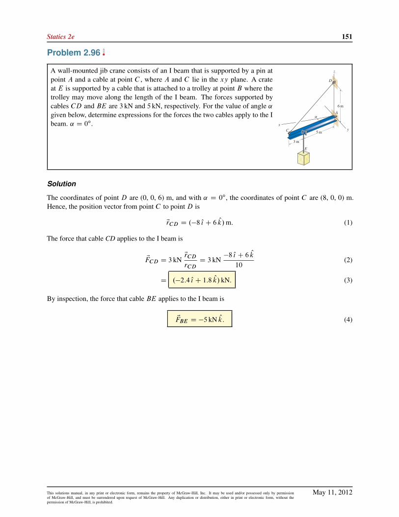
Statics 2e 151
Problem 2.96
A wall-mounted jib crane consists of an I beam that is supported by a pin atpoint A and a cable at point C , where A and C lie in the xy plane. A crateat E is supported by a cable that is attached to a trolley at point B where thetrolley may move along the length of the I beam. The forces supported bycables CD and BE are 3 kN and 5 kN, respectively. For the value of angle ˛given below, determine expressions for the forces the two cables apply to the Ibeam. ˛ D 0ı.
Solution
The coordinates of point D are (0, 0, 6) m, and with ˛ D 0ı, the coordinates of point C are (8, 0, 0) m.Hence, the position vector from point C to point D is
ErCD D .�8 O{ C 6 Ok/m: (1)
The force that cable CD applies to the I beam is
EFCD D 3 kNErCD
rCDD 3 kN
�8 O{ C 6 Ok
10(2)
D .�2:4 O{ C 1:8 Ok/ kN. (3)
By inspection, the force that cable BE applies to the I beam is
EFBE D �5 kN Ok: (4)
May 11, 2012This solutions manual, in any print or electronic form, remains the property of McGraw-Hill, Inc. It may be used and/or possessed only by permissionof McGraw-Hill, and must be surrendered upon request of McGraw-Hill. Any duplication or distribution, either in print or electronic form, without thepermission of McGraw-Hill, is prohibited.

152 Solutions Manual
Problem 2.97
A wall-mounted jib crane consists of an I beam that is supported by a pin atpoint A and a cable at point C , where A and C lie in the xy plane. A crateat E is supported by a cable that is attached to a trolley at point B where thetrolley may move along the length of the I beam. The forces supported bycables CD and BE are 3 kN and 5 kN, respectively. For the value of angle ˛given below, determine expressions for the forces the two cables apply to the Ibeam. ˛ D 40ı.
Solution
The coordinates of point D are (0, 0, 6) m, and with ˛ D 40ı, the coordinates of point C are (8 m cos 40ı,8 m sin 40ı, 0). Hence, the position vector from point C to point D is
ErCD D .�6:128 O{ � 5:142 O| C 6 Ok/m: (1)
The force that cable CD applies to the I beam is
EFCD D 3 kNErCD
rCDD 3 kN
�6:128 O{ � 5:142 O| C 6 Ok
10:00(2)
D .�1:839 O{ � 1:543 O| C 1:800 Ok/ kN. (3)
By inspection, the force that cable BE applies to the I beam is
EFBE D �5 kN Ok: (4)
May 11, 2012This solutions manual, in any print or electronic form, remains the property of McGraw-Hill, Inc. It may be used and/or possessed only by permissionof McGraw-Hill, and must be surrendered upon request of McGraw-Hill. Any duplication or distribution, either in print or electronic form, without thepermission of McGraw-Hill, is prohibited.
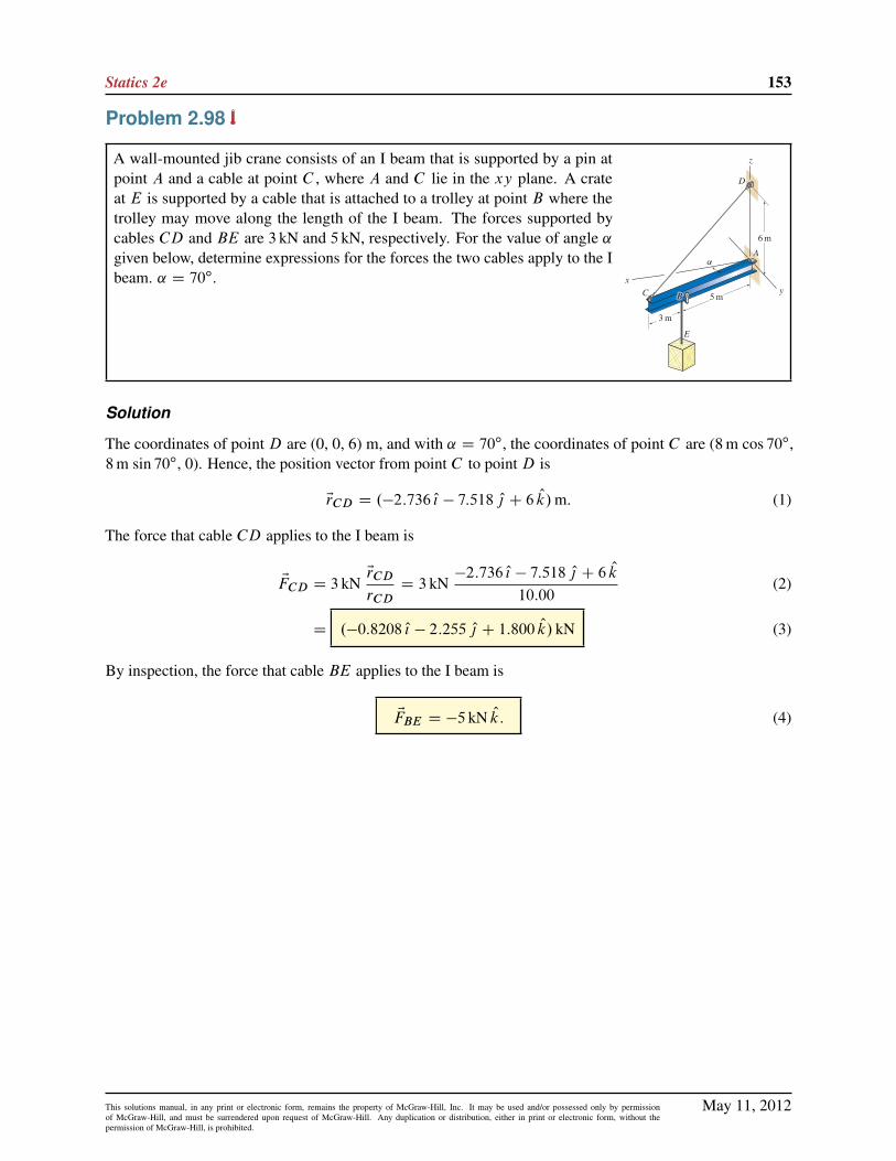
Statics 2e 153
Problem 2.98
A wall-mounted jib crane consists of an I beam that is supported by a pin atpoint A and a cable at point C , where A and C lie in the xy plane. A crateat E is supported by a cable that is attached to a trolley at point B where thetrolley may move along the length of the I beam. The forces supported bycables CD and BE are 3 kN and 5 kN, respectively. For the value of angle ˛given below, determine expressions for the forces the two cables apply to the Ibeam. ˛ D 70ı.
Solution
The coordinates of point D are (0, 0, 6) m, and with ˛ D 70ı, the coordinates of point C are (8 m cos 70ı,8 m sin 70ı, 0). Hence, the position vector from point C to point D is
ErCD D .�2:736 O{ � 7:518 O| C 6 Ok/m: (1)
The force that cable CD applies to the I beam is
EFCD D 3 kNErCD
rCDD 3 kN
�2:736 O{ � 7:518 O| C 6 Ok
10:00(2)
D .�0:8208 O{ � 2:255 O| C 1:800 Ok/ kN (3)
By inspection, the force that cable BE applies to the I beam is
EFBE D �5 kN Ok: (4)
May 11, 2012This solutions manual, in any print or electronic form, remains the property of McGraw-Hill, Inc. It may be used and/or possessed only by permissionof McGraw-Hill, and must be surrendered upon request of McGraw-Hill. Any duplication or distribution, either in print or electronic form, without thepermission of McGraw-Hill, is prohibited.
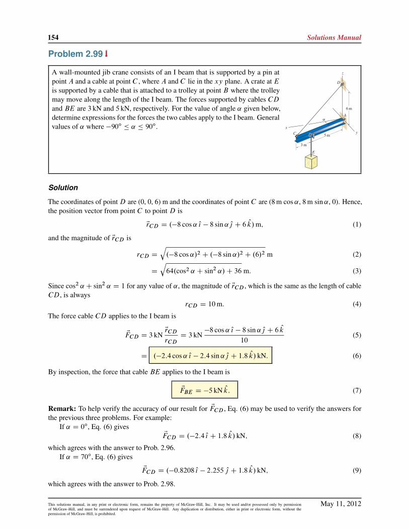
154 Solutions Manual
Problem 2.99
A wall-mounted jib crane consists of an I beam that is supported by a pin atpoint A and a cable at point C , where A and C lie in the xy plane. A crate at Eis supported by a cable that is attached to a trolley at point B where the trolleymay move along the length of the I beam. The forces supported by cables CDand BE are 3 kN and 5 kN, respectively. For the value of angle ˛ given below,determine expressions for the forces the two cables apply to the I beam. Generalvalues of ˛ where �90ı � ˛ � 90ı.
Solution
The coordinates of pointD are (0, 0, 6) m and the coordinates of point C are (8 m cos˛, 8 m sin˛, 0). Hence,the position vector from point C to point D is
ErCD D .�8 cos˛ O{ � 8 sin˛ O| C 6 Ok/m; (1)
and the magnitude of ErCD is
rCD D
q.�8 cos˛/2 C .�8 sin˛/2 C .6/2 m (2)
D
q64.cos2 ˛ C sin2 ˛/C 36 m: (3)
Since cos2 ˛C sin2 ˛ D 1 for any value of ˛, the magnitude of ErCD , which is the same as the length of cableCD, is always
rCD D 10m: (4)
The force cable CD applies to the I beam is
EFCD D 3 kNErCD
rCDD 3 kN
�8 cos˛ O{ � 8 sin˛ O| C 6 Ok10
(5)
D .�2:4 cos˛ O{ � 2:4 sin˛ O| C 1:8 Ok/ kN. (6)
By inspection, the force that cable BE applies to the I beam is
EFBE D �5 kN Ok: (7)
Remark: To help verify the accuracy of our result for EFCD , Eq. (6) may be used to verify the answers forthe previous three problems. For example:
If ˛ D 0ı, Eq. (6) givesEFCD D .�2:4 O{ C 1:8 Ok/ kN; (8)
which agrees with the answer to Prob. 2.96.If ˛ D 70ı, Eq. (6) gives
EFCD D .�0:8208 O{ � 2:255 O| C 1:8 Ok/ kN; (9)
which agrees with the answer to Prob. 2.98.
May 11, 2012This solutions manual, in any print or electronic form, remains the property of McGraw-Hill, Inc. It may be used and/or possessed only by permissionof McGraw-Hill, and must be surrendered upon request of McGraw-Hill. Any duplication or distribution, either in print or electronic form, without thepermission of McGraw-Hill, is prohibited.

Statics 2e 155
Problem 2.100
A coordinate system that is often used for problems in mechanics is the sphericalcoordinate system, as shown. With this coordinate system, the location of apoint P in three dimensions is specified using a radial distance r where r � 0,an angle � (sometimes called the azimuthal angle) where 0ı � � � 360ı, andan angle � (sometimes called the polar angle) where 0ı � � � 180ı. If valuesfor r, � , and � are known, determine the direction angles for the position vectorfrom the origin of the coordinate system to point P .
Solution
By examining the figure provided in the problem statement, note that � is measured from the positive ´direction to the direction of vector ErOP ; hence � is a direction angle and thus
�´ D �: (1)
Using the sketch shown at the right, we determine the projection of ErOP
in the a direction to bera D r sin�: (2)
The projections of ra in the x and y directions are then
rx D ra cos � D r sin� cos �; (3)
ry D ra sin � D r sin� sin �: (4)
The x and y direction angles are thus
�x D cos�1 rx
rD cos�1 r sin� cos �
r(5)
D cos�1.sin� cos �/, (6)
�y D cos�1 ry
rD cos�1 r sin� sin �
r(7)
D cos�1.sin� sin �/. (8)
To help verify the accuracy of these results, you may wish to verify that cos2 �x C cos2 �y C cos2 �´ D 1 forany values of � and � .
May 11, 2012This solutions manual, in any print or electronic form, remains the property of McGraw-Hill, Inc. It may be used and/or possessed only by permissionof McGraw-Hill, and must be surrendered upon request of McGraw-Hill. Any duplication or distribution, either in print or electronic form, without thepermission of McGraw-Hill, is prohibited.

156 Solutions Manual
Problem 2.101
For the spherical coordinate system described in Prob. 2.100, if the directionangles for the position vector from the origin of the coordinate system to pointP are known, determine the values for r , � , and �. Hint: Several approachesmay be used to solve this problem, but a straightforward solution is to first solveProb. 2.100, and then use those results to solve this problem.
Solution
Following the hint given in the problem statement, we first solve Prob. 2.100 to obtain the results
�´ D �; (1)
�x D cos�1.sin� cos �/; (2)
�y D cos�1.sin� sin �/: (3)
From Eq. (1),
� D �´: (4)
Taking the cosine of both sides of Eq. (2), and combining with Eq. (4), provides
cos �x D sin� cos � (5)
D sin �´ cos �: (6)
Solving Eq. (6) for � provides
� D cos�1 cos �x
sin �´: (7)
As an alternative to Eqs. (5) – (7), we could take the cosine of both sides of Eq. (3) to obtain
� D sin�1 cos �y
sin �´: (8)
Equations (7) and (8) yield the same result for � , and either may be used. Also:
It is not possible to determine r if only the direction angles �x , �y , and �´ are known.
May 11, 2012This solutions manual, in any print or electronic form, remains the property of McGraw-Hill, Inc. It may be used and/or possessed only by permissionof McGraw-Hill, and must be surrendered upon request of McGraw-Hill. Any duplication or distribution, either in print or electronic form, without thepermission of McGraw-Hill, is prohibited.

Statics 2e 157
Problem 2.102
The rear wheel of a multispeed bicycle is shown. The wheel has 32 spokes, with one-half being on eitherside (spokes on sides A and B are shown in the figure in black and red, respectively). For the tire to beproperly centered on the frame of the bicycle, points A and B of the hub must be positioned at the samedistance d from the centerline of the tire. To make room for the sprocket cluster, bicycle manufacturersgive spokes on side B of the wheel a different orientation than spokes on side A. For the followingquestions, assume the tire is in the process of being manufactured, so that all spokes on side A have thesame force FA and all spokes on side B have the same force FB .
(a) Determine the ratio of spoke forces FB=FA so that the resultant force in the x direction applied tothe hub by all 32 spokes is zero. Hint: Although each spoke has a different orientation, all spokes onside A have the same length, and similarly all spokes on side B have the same length. Furthermore,all spokes on side A have the same x component of force, and all spokes on side B have the same xcomponent of force.
(b) On which side of the wheel are the spokes most severely loaded?
(c) Briefly describe a new design in which spokes on both sides of the wheel are equally loaded andpoints A and B are at the same distance d from the centerline of the tire.
Solution
Part (a) Consider the two spokes shown in the figure at the right. Spoke AC is onside A of the wheel, and spoke BC is on side B of the wheel, where point C is thelocation where the two spokes attach to the rim of the wheel. Based on the geometryprovided in the problem statement, position vectors from points A to C , and frompoints B to C may be written as
ErAC D�3:8 O{ C 2:5 O| C 26:5 Ok
�cm; ErBC D
��2:5 O{ C 2:5 O| C 26:5 Ok
�cm: (1)
May 11, 2012This solutions manual, in any print or electronic form, remains the property of McGraw-Hill, Inc. It may be used and/or possessed only by permissionof McGraw-Hill, and must be surrendered upon request of McGraw-Hill. Any duplication or distribution, either in print or electronic form, without thepermission of McGraw-Hill, is prohibited.

158 Solutions Manual
Unit vectors in the directions of ErAC and ErBC are
OuAC DErAC
jErAC jD
.3:8 O{ C 2:5 O| C 26:5 Ok/ cmp
.3:8/2 C .2:5/2 C .26:5/2 cmD 0:1413 O{ C 0:09298 O| C 0:9856 Ok; (2)
OuBC DErBC
jErBC jD
.�2:5 O{ C 2:5 O| C 26:5 Ok/ cmp
.�2:5/2 C .2:5/2 C .26:5/2 cmD �0:09351 O{ C 0:09351 O| C 0:9912 Ok: (3)
Let EFA be the force supported by spoke AC , and EFB be the force supported by spoke BC . Then,
EFA D FA OuAC D FA.0:1413 O{ C 0:09298 O| C 0:9856 Ok/; (4)
EFB D FB OuBC D FB.�0:09351 O{ C 0:09351 O| C 0:9912 Ok/: (5)
The net force applied by all of the spokes to the hub is obtained by adding the force vectors for all 32 spokes.Although each spoke will have different components of force in the y and ´ directions, depending upon eachspoke’s location around the wheel, all of the spokes on side A will have the same x component of force, andsimilarly, all of the spokes on side B will have the same x component of force. Since each side has the samenumber of spokes, we can consider the sum of forces EFA C
EFB , with the requirement that the x componentof this be zero. Thus, we add the x components of Eqs. (4) and (5) to obtain
FA.0:1413/C FB.�0:09351/ D 0: (6)
From Eq. (6), the ratio FB=FA is given by
FB=FA D 0:1413=0:09351 D 1:51: (7)
Part (b) Based on the ratio of Eq. (7),
the spokes on side B of the wheel are more severely loaded,
with approximately 50% higher force than the spokes on side A.
Part (c) Solution not provided.
Photo credit: © Erik Isakson/ Rubberball Productions/Getty RF.
May 11, 2012This solutions manual, in any print or electronic form, remains the property of McGraw-Hill, Inc. It may be used and/or possessed only by permissionof McGraw-Hill, and must be surrendered upon request of McGraw-Hill. Any duplication or distribution, either in print or electronic form, without thepermission of McGraw-Hill, is prohibited.

Statics 2e 159
Problem 2.103
(a) Determine the angle between vectors EA and EB .
(b) Determine the components of EA parallel and perpendicular to EB .
(c) Determine the vector components of EA parallel and perpendicular to EB .
Solution
Part (a) Begin by computing the magnitudes of the vectors EA and EB
A D
q.�1/2 C .8/2 C .4/2 N D 9N; B D
q.1/2 C .18/2 C .�6/2 mm D 19mm: (1)
The angle � between these vectors is given by
� D cos�1
EA � EB
AB
!D cos�1
".�1N/.1mm/C .8N/.18mm/C .4N/.�6mm/
.9N/.19mm/
#(2)
D cos�1
119
171
!D 45:9ı. (3)
Part (b) The parallel component of EA is given by Ak and the perpendicular component is given by A?,such that
Ak D EA �EB
BD.�1N/.1mm/C .8N/.18mm/C .4N/.�6mm/
19mmD 6:26N;
A? DqA2 � A2
kD
q.9N/2 � .6:263N/2 D 6:46N:
(4)
(5)
Part (c) The vector component of EA parallel to EB is given by
EAk D Ak �EB
BD .6:263N/
.O{ C 18 O| � 6 Ok/mm
19mm
!D .0:330 O{ C 5:93 O| � 1:98 Ok/N: (6)
The perpendicular vector component is then
EA? D EA � EAk D .�O{ C 8 O| C 4 Ok/N � .0:3296 O{ C 5:934 O| � 1:978 Ok/N;
D .�1:33 O{ C 2:07 O| C 5:98 Ok/N: (7)
As a partial check of the accuracy of our results, we evaluate the magnitude of Eq. (7) to obtain
A? D
q.�1:330N/2 C .2:066N/2 C .5:978N/2 D 6:46N; (8)
which agrees with the value found in Eq. (5).
May 11, 2012This solutions manual, in any print or electronic form, remains the property of McGraw-Hill, Inc. It may be used and/or possessed only by permissionof McGraw-Hill, and must be surrendered upon request of McGraw-Hill. Any duplication or distribution, either in print or electronic form, without thepermission of McGraw-Hill, is prohibited.
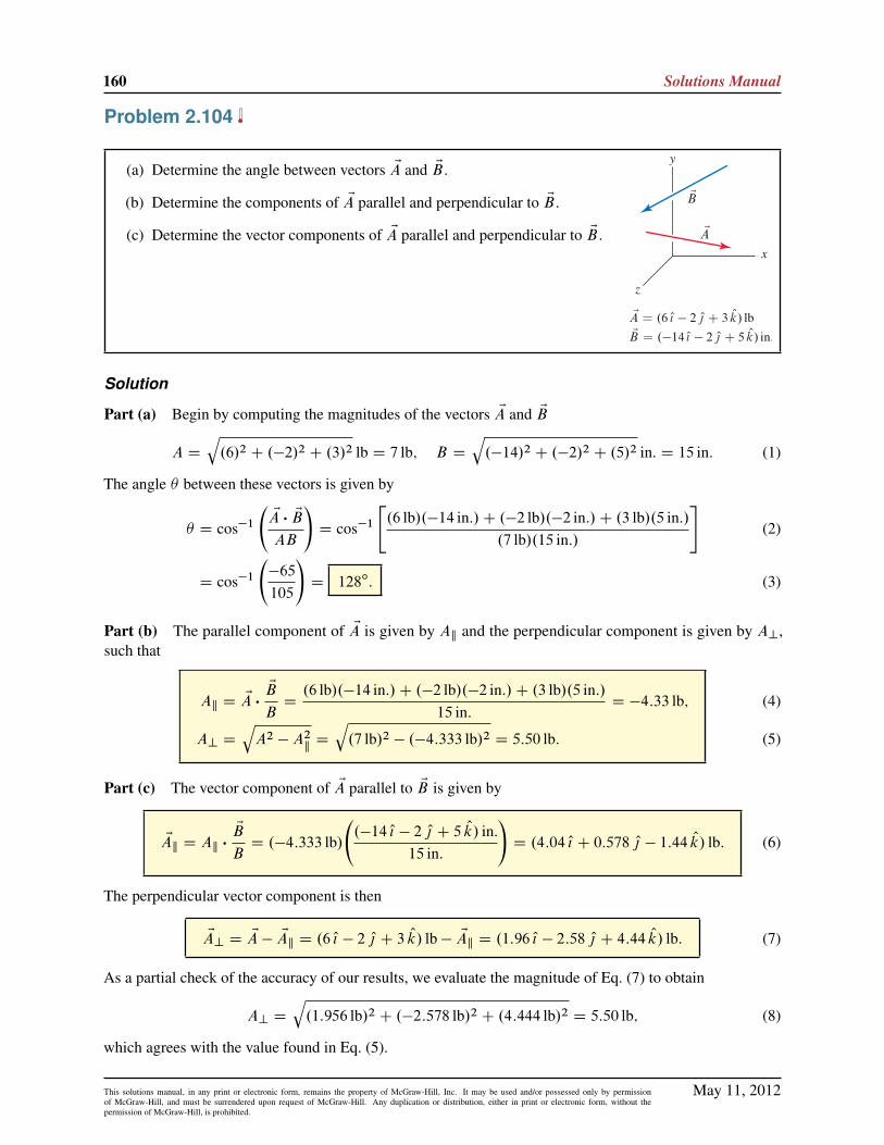
160 Solutions Manual
Problem 2.104
(a) Determine the angle between vectors EA and EB .
(b) Determine the components of EA parallel and perpendicular to EB .
(c) Determine the vector components of EA parallel and perpendicular to EB .
Solution
Part (a) Begin by computing the magnitudes of the vectors EA and EB
A D
q.6/2 C .�2/2 C .3/2 lb D 7 lb; B D
q.�14/2 C .�2/2 C .5/2 in. D 15 in: (1)
The angle � between these vectors is given by
� D cos�1
EA � EB
AB
!D cos�1
".6 lb/.�14 in:/C .�2 lb/.�2 in:/C .3 lb/.5 in:/
.7 lb/.15 in:/
#(2)
D cos�1
�65
105
!D 128ı. (3)
Part (b) The parallel component of EA is given by Ak and the perpendicular component is given by A?,such that
Ak D EA �EB
BD.6 lb/.�14 in:/C .�2 lb/.�2 in:/C .3 lb/.5 in:/
15 in:D �4:33 lb;
A? DqA2 � A2
kD
q.7 lb/2 � .�4:333 lb/2 D 5:50 lb:
(4)
(5)
Part (c) The vector component of EA parallel to EB is given by
EAk D Ak �EB
BD .�4:333 lb/
.�14 O{ � 2 O| C 5 Ok/ in.
15 in:
!D .4:04 O{ C 0:578 O| � 1:44 Ok/ lb: (6)
The perpendicular vector component is then
EA? D EA � EAk D .6 O{ � 2 O| C 3 Ok/ lb � EAk D .1:96 O{ � 2:58 O| C 4:44 Ok/ lb: (7)
As a partial check of the accuracy of our results, we evaluate the magnitude of Eq. (7) to obtain
A? D
q.1:956 lb/2 C .�2:578 lb/2 C .4:444 lb/2 D 5:50 lb; (8)
which agrees with the value found in Eq. (5).
May 11, 2012This solutions manual, in any print or electronic form, remains the property of McGraw-Hill, Inc. It may be used and/or possessed only by permissionof McGraw-Hill, and must be surrendered upon request of McGraw-Hill. Any duplication or distribution, either in print or electronic form, without thepermission of McGraw-Hill, is prohibited.

Statics 2e 161
Problem 2.105
(a) Determine the angle between vectors EA and EB .
(b) Determine the components of EA parallel and perpendicular to EB .
(c) Determine the vector components of EA parallel and perpendicular to EB .
Solution
Part (a) The magnitudes of vectors EA and EB are
A D
q.�12/2 C .16/2 C .�15/2 lb D 25 lb; B D
q.18/2 C .6/2 C .�13/2 in: D 23 in. (1)
The angle � between these vectors is
� D cos�1
EA � EB
AB
!D cos�1
�.�12 lb/.18 in./C .16 lb/.6 in./C .�15 lb/.�13 in./
.25 lb/.23 in./
�(2)
D cos�1
�75
575
�D 82:51ı: (3)
Part (b) The parallel component of EA is given by Ak and the perpendicular component is given by A?;where
Ak D EA �EB
BD.�12 lb/.18 in./C .16 lb/.6 in./C .�15 lb/.�13 in./
23 in.D 3:261 lb;
A? DqA2 � A2
kD
q.25 lb/2 � .3:261 lb/2 D 24:79 lb.
(4)
(5)
Part (c) The vector component of EA parallel to EB is
EAk D AkEB
BD 3:261 lb
.18 O{ C 6 O| � 13 Ok/ in.23 in.
D .2:552 O{ C 0:8507 O| � 1:843 Ok/ lb: (6)
The perpendicular vector component is
EA? D EA � EAk D .�12 O{ C 16 O| � 15 Ok/ lb � .2:552 O{ C 0:8507 O| � 1:843 Ok/ lb
D .�14:55 O{ C 15:15 O| � 13:16 Ok/ lb:
(7)
(8)
As a partial check of accuracy of our results, we evaluate the magnitude of Eq. (8) to obtain
A? D
q.�14:55 lb/2 C .15:15 lb/2 C .�13:16 lb/2 D 24:79 lb; (9)
which agrees with the value found in Eq. (5).
May 11, 2012This solutions manual, in any print or electronic form, remains the property of McGraw-Hill, Inc. It may be used and/or possessed only by permissionof McGraw-Hill, and must be surrendered upon request of McGraw-Hill. Any duplication or distribution, either in print or electronic form, without thepermission of McGraw-Hill, is prohibited.

162 Solutions Manual
Problem 2.106
(a) Determine the angle between vectors EA and EB .
(b) Determine the components of EA parallel and perpendicular to EB .
(c) Determine the vector components of EA parallel and perpendicular to EB .
Solution
Part (a) The magnitude of vectors EA and EB are
A D
q.4/2 C .3/2 C .12/2 N D 13N, B D
q.�2/2 C .5/2 C .�14/2 m D 15 m. (1)
The angle � between these vectors is
� D cos�1
EA � EB
AB
!D cos�1
�.4 N/.�2 m/C .3 N/.5 m/C .12 N/.�14 m/
.13 N/.15 m/
�(2)
D cos�1 �161
195D 145:7ı: (3)
Part (b) The parallel component of EA is given by Ak and the perpendicular component is given by A?,where
Ak D EA �EB
BD.4 N/.�2 m/C .3 N/.5 m/C .12 N/.�14 m/
15 mD �10:73 N;
A? DqA2 � A2
kD
q.13 N/2 � .�10:73 N/2 D 7:335 N.
(4)
(5)
Part (c) The vector component of EA parallel to EB is
EAk D AkEB
BD �10:73 N
.�2 O{ C 5 O| � 14 Ok/m15 m
D .1:431 O{ � 3:578 O| C 10:02 Ok/N: (6)
The perpendicular vector component is
EA? D EA � EAk D .4 O{ C 3 O| C 12 Ok/N � .1:431 O{ � 3:578 O| C 10:02 Ok/N
D .2:569 O{ C 6:578 O| C 1:982 Ok/N:
(7)
(8)
As a partial check of accuracy of our results, we evaluate the magnitude of Eq. (8) to obtain
A? D
q.2:569 N/2 C .6:578 N/2 C .1:982 N/2 D 7:335 N; (9)
which agrees with the value found in Eq. (5).
May 11, 2012This solutions manual, in any print or electronic form, remains the property of McGraw-Hill, Inc. It may be used and/or possessed only by permissionof McGraw-Hill, and must be surrendered upon request of McGraw-Hill. Any duplication or distribution, either in print or electronic form, without thepermission of McGraw-Hill, is prohibited.
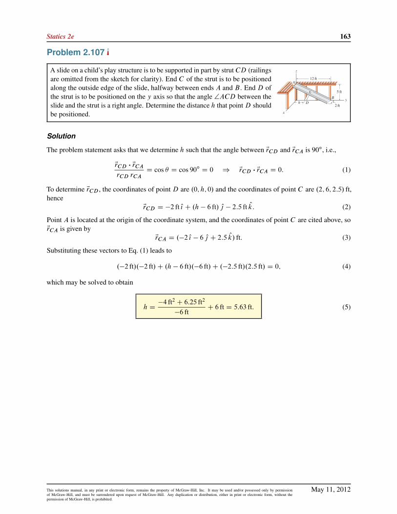
Statics 2e 163
Problem 2.107
A slide on a child’s play structure is to be supported in part by strut CD (railingsare omitted from the sketch for clarity). End C of the strut is to be positionedalong the outside edge of the slide, halfway between ends A and B . End D ofthe strut is to be positioned on the y axis so that the angle †ACD between theslide and the strut is a right angle. Determine the distance h that pointD shouldbe positioned.
Solution
The problem statement asks that we determine h such that the angle between ErCD and ErCA is 90ı, i.e.,
ErCD � ErCA
rCD rCAD cos � D cos 90ı D 0 ) ErCD � ErCA D 0: (1)
To determine ErCD , the coordinates of point D are .0; h; 0/ and the coordinates of point C are .2; 6; 2:5/ ft,hence
ErCD D �2 ft O{ C .h � 6 ft/ O| � 2:5 ft Ok: (2)
Point A is located at the origin of the coordinate system, and the coordinates of point C are cited above, soErCA is given by
ErCA D .�2 O{ � 6 O| C 2:5 Ok/ ft: (3)
Substituting these vectors to Eq. (1) leads to
.�2 ft/.�2 ft/C .h � 6 ft/.�6 ft/C .�2:5 ft/.2:5 ft/ D 0; (4)
which may be solved to obtain
h D�4 ft2 C 6:25 ft2
�6 ftC 6 ft D 5:63 ft: (5)
May 11, 2012This solutions manual, in any print or electronic form, remains the property of McGraw-Hill, Inc. It may be used and/or possessed only by permissionof McGraw-Hill, and must be surrendered upon request of McGraw-Hill. Any duplication or distribution, either in print or electronic form, without thepermission of McGraw-Hill, is prohibited.

164 Solutions Manual
Problem 2.108
A whistle is made of a square tube with a notch cut in its edge, into which abaffle is brazed. Determine the dimensions d and � for the baffle.
Solution
Let points A, B , and C be located at the three corners of thetriangular baffle, as shown. Position vectors may then be writtenas
ErAB D .5:774 cm/.cos 60ı O{ C sin 60ı Ok/; (1)
ErAC D .5:774 cm/.cos 60ı O| C sin 60ı Ok/: (2)
(3)
From the geometry shown at the right, the dimension d of thebaffle is
d D 5:77 cm: (4)
The angle � for the baffle, which is the angle between vectorsEr/AB and rAC , is given by
� D cos�1
ErAB � ErAC
rAB rAC
!(5)
D cos�1
"�.5:774 cm/.cos 60ı O{ C sin 60ı Ok/
���.5:774 cm/.cos 60ı O| C sin 60ı Ok/
�.5:774 cm/.5:774 cm/
#(6)
D cos�1�.cos 60ı/.0/C .0/.cos 60ı/C .sin 60ı/.sin 60ı/
�D cos�1.0:75/; (7)
such that� D 41:4ı: (8)
May 11, 2012This solutions manual, in any print or electronic form, remains the property of McGraw-Hill, Inc. It may be used and/or possessed only by permissionof McGraw-Hill, and must be surrendered upon request of McGraw-Hill. Any duplication or distribution, either in print or electronic form, without thepermission of McGraw-Hill, is prohibited.

Statics 2e 165
Problem 2.109
A flat, triangular-shaped window for the cockpit of an airplane is to have thecorner coordinates shown. Specify the angles �A, �B , and �C and dimensionsdAB , dBC , and dAC for the window.
Solution
Begin by writing the following vectors:
ErAB D�.�25 � 35/ O{ C .30 � 25/ O| C .105 � 90/ Ok
�cm D .�60 O{ C 5 O| C 15 Ok/ cm; (1)
ErAC D�.15 � 35/ O{ C .60 � 25/ O| C .80 � 90/ Ok
�cm D .�20 O{ C 35 O| � 10 Ok/ cm; (2)
ErBC D�.15 � .�25// O{ C .60 � 30/ O| C .80 � 105/ Ok
�cm D .40 O{ C 30 O| � 25 Ok/ cm: (3)
The magnitudes of these vectors are
rAB D rBA D
q.�60/2 C 52 C 152 cm D 62:05 cm; (4)
rAC D rCA D
q.�20/2 C 352 C .�10/2 cm D 41:53 cm; (5)
rBC D rCB D
q402 C 302 C .�25/2 cm D 55:90 cm: (6)
The dimensions dAB , dBC , and dAC corresponding to these magnitudes areshown at the right, and are given by
dAB D 62:05 cm; dBC D 55:90 cm; dAC D 41:53 cm: (7)
Before determining the angles, consider the following dot products (where ErBA D �ErAB , etc.),
ErAB � ErAC D .�60 O{ C 5 O| C 15 Ok/ cm � .�20 O{ C 35 O| � 10 Ok/ cm D 1225 cm2; (8)
ErBC � ErBA D .40 O{ C 30 O| � 25 Ok/ cm � .60 O{ � 5 O| � 15 Ok/ cm D 2625 cm2; (9)
ErCB � ErCA D .�40 O{ � 30 O| C 25 Ok/ cm � .20 O{ � 35 O| C 10 Ok/ cm D 500 cm2: (10)
The angles are then found using
�A D cos�1
ErAB � ErAC
rAB rAC
!D cos�1
"1225 cm2
.62:05 cm/.41:53 cm/
#D 61:6ı;
�B D cos�1
ErBC � ErBA
rBC rBA
!D cos�1
"2625 cm2
.55:90 cm/.62:05 cm/
#D 40:8ı;
�C D cos�1
ErCB � ErCA
rCB rCA
!D cos�1
"500 cm2
.55:90 cm/.41:53 cm/
#D 77:6ı:
(11)
(12)
(13)
As a partial check of accuracy, we may add the above angles to verify that their sum equals 180ı, i.e.,
�A C �B C �C D 61:62ıC 40:82ı C 77:56ı D 180ı: (14)
May 11, 2012This solutions manual, in any print or electronic form, remains the property of McGraw-Hill, Inc. It may be used and/or possessed only by permissionof McGraw-Hill, and must be surrendered upon request of McGraw-Hill. Any duplication or distribution, either in print or electronic form, without thepermission of McGraw-Hill, is prohibited.

166 Solutions Manual
Problem 2.110
The corner of an infant’s bassinet is shown. Determine angles ˛ and ˇ anddimensions a and b of the side and end pieces so the corners of the bassinetwill properly meet when assembled.
Solution
The top two figures to the right are used to find the dimension a and theangle ˛. Based on these figures, we obtain
ErAB D .�O{ � 2 O| C 12 Ok/ in.; (1)
rAB D
q.�1/2 C .�2/2 C .12/2 in. D 12:21 in:; (2)
ErAC D .�2 O| C 12 Ok/ in.; (3)
rAC D
q.�2/2 C .12/2 in. D 12:17 in: (4)
The bottom two figures to the right are used to find ErAD and rAD , suchthat
ErAD D
��O{ C 12 Ok
�in.; (5)
rAD D
q.�1/2 C .12/2 in. D 12:04 in: (6)
The angles ˛ and ˇ are given by
˛ D cos�1
ErAC � ErAB
rAC rAB
!D cos�1
0C .�2/.�2/C .12/.12/
.12:17/.12:21/
!D 4:70ı;
ˇ D cos�1
ErAD � ErAB
rAD rAB
!D cos�1
.�1/.�1/C 0C .12/.12/
.12:04/.12:21/
!D 9:43ı:
(7)
(8)
The dimensions a and b are given by the magnitudes rAC and rAD , such that
a D rAC D 12:2 in:; b D rAD D 12:0 in: (9)
May 11, 2012This solutions manual, in any print or electronic form, remains the property of McGraw-Hill, Inc. It may be used and/or possessed only by permissionof McGraw-Hill, and must be surrendered upon request of McGraw-Hill. Any duplication or distribution, either in print or electronic form, without thepermission of McGraw-Hill, is prohibited.

Statics 2e 167
Problem 2.111
The roof of an 8 ft diameter grain silo is to be made using 12 identical triangularpanels. Determine the value of angle � needed and the smallest value of d thatcan be used.
Solution
The figure to the right shows a single triangular panel of the roof. Sincethere are 12 such panels, the projected angle of each panel onto thex´ plane is 360ı=12 D 30ı. With the x axis taken to be through themiddle of the panel, the angle to each side of the horizontal projectionis 30ı=2 D 15ı, as shown. To determine the smallest value d may have,we use the radius of the silo (4 ft) as the length in the x direction fromthe origin of the coordinate system to the edge of the panel, as shown.Our strategy is to write expressions for vectors ErAB and ErAC , and thenuse the dot product between these to determine � . These vectors, andtheir magnitudes, are given by
ErAB D .4 O{ � 2 O| C 1:072 Ok/ ft; rAB D
q.4/2 C .�2/2 C .1:072/2 ft D 4:599 ft; (1)
ErAC D .4 O{ � 2 O| � 1:072 Ok/ ft; rAB D
q.4/2 C .�2/2 C .�1:072/2 ft D 4:599 ft: (2)
The angle � is found using
� D cos�1
ErAB � ErAC
rAB rAC
!D cos�1
".4/.4/C .�2/.�2/C .1:072/.�1:072/
.4:590/.4:599/
#D 27:0ı: (3)
The distance d is given by either magnitude rAB or rAC , i.e.,
d D 4:60 ft: (4)
May 11, 2012This solutions manual, in any print or electronic form, remains the property of McGraw-Hill, Inc. It may be used and/or possessed only by permissionof McGraw-Hill, and must be surrendered upon request of McGraw-Hill. Any duplication or distribution, either in print or electronic form, without thepermission of McGraw-Hill, is prohibited.
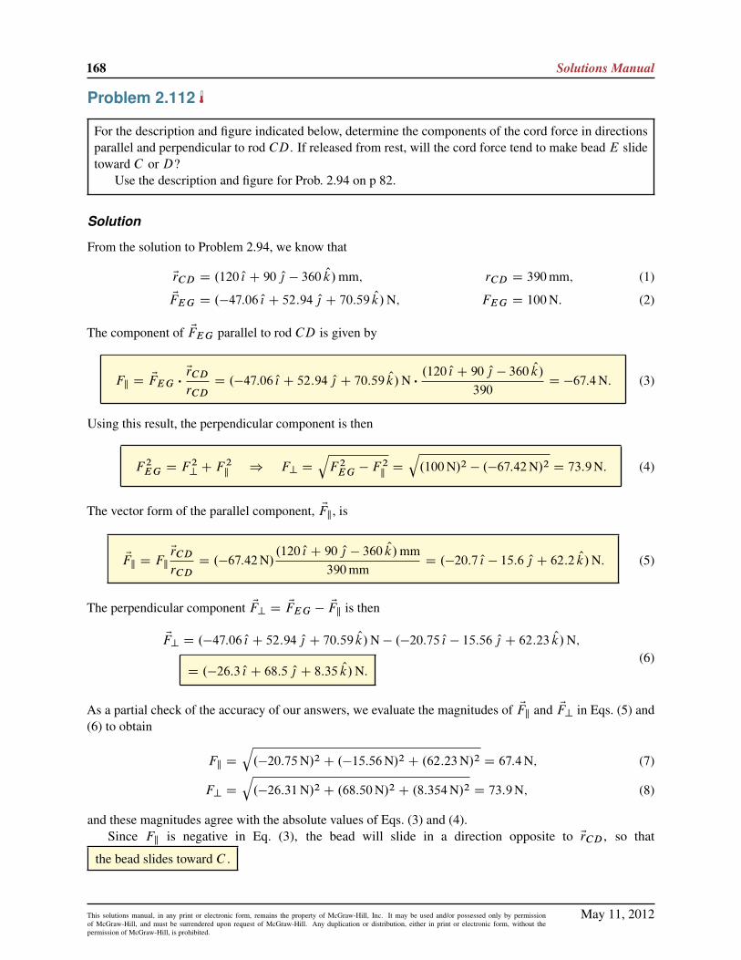
168 Solutions Manual
Problem 2.112
For the description and figure indicated below, determine the components of the cord force in directionsparallel and perpendicular to rod CD. If released from rest, will the cord force tend to make bead E slidetoward C or D?
Use the description and figure for Prob. 2.94 on p 82.
Solution
From the solution to Problem 2.94, we know that
ErCD D .120 O{ C 90 O| � 360 Ok/mm; rCD D 390mm; (1)
EFEG D .�47:06 O{ C 52:94 O| C 70:59 Ok/N; FEG D 100N: (2)
The component of EFEG parallel to rod CD is given by
Fk D EFEG �ErCD
rCDD .�47:06 O{ C 52:94 O| C 70:59 Ok/N �
.120 O{ C 90 O| � 360 Ok/
390D �67:4N: (3)
Using this result, the perpendicular component is then
F 2EG D F
2? C F
2k) F? D
qF 2
EG � F2kD
q.100N/2 � .�67:42N/2 D 73:9N: (4)
The vector form of the parallel component, EFk, is
EFk D FkErCD
rCDD .�67:42N/
.120 O{ C 90 O| � 360 Ok/mm390mm
D .�20:7 O{ � 15:6 O| C 62:2 Ok/N: (5)
The perpendicular component EF? D EFEG �EFk is then
EF? D .�47:06 O{ C 52:94 O| C 70:59 Ok/N � .�20:75 O{ � 15:56 O| C 62:23 Ok/N;
D .�26:3 O{ C 68:5 O| C 8:35 Ok/N.(6)
As a partial check of the accuracy of our answers, we evaluate the magnitudes of EFk and EF? in Eqs. (5) and(6) to obtain
Fk D
q.�20:75N/2 C .�15:56N/2 C .62:23N/2 D 67:4N; (7)
F? D
q.�26:31N/2 C .68:50N/2 C .8:354N/2 D 73:9N; (8)
and these magnitudes agree with the absolute values of Eqs. (3) and (4).Since Fk is negative in Eq. (3), the bead will slide in a direction opposite to ErCD , so that
the bead slides toward C .
May 11, 2012This solutions manual, in any print or electronic form, remains the property of McGraw-Hill, Inc. It may be used and/or possessed only by permissionof McGraw-Hill, and must be surrendered upon request of McGraw-Hill. Any duplication or distribution, either in print or electronic form, without thepermission of McGraw-Hill, is prohibited.

Statics 2e 169
Problem 2.113
For the description and figure indicated below, determine the components of the cord force in directionsparallel and perpendicular to rod CD. If released from rest, will the cord force tend to make bead E slidetoward C or D?
Use the description and figure for Prob. 2.95 on p 82.
Solution
From the solution to Problem 2.95, we know that
ErCD D .90 O{ C 120 O| � 360 Ok/mm; rCD D 390mm; (1)
EFEG D .�33:33 O{ C 66:67 O| C 66:67 Ok/N; FEG D 100N: (2)
The component of EFEG parallel to rod CD is given by
Fk D EFEG �ErCD
rCDD .�33:33 O{ C 66:67 O| C 66:67 Ok/N �
.90 O{ C 120 O| � 360 Ok/mm390mm
D �48:7N:
(3)
Using this result, the perpendicular component is then
F 2EG D F
2? C F
2k) F? D
qF 2
EG � F2kD
q.100N/2 � .�48:72N/2 D 87:3N: (4)
The vector form of the parallel component, EFk, is
EFk D FkErCD
rCDD .�48:72N/
.90 O{ C 120 O| � 360 Ok/mm390mm
D .�11:2 O{ � 15:0 O| C 45:0 Ok/N: (5)
The perpendicular component EF? D EFEG �EFk is then
EF? D .�33:33 O{ C 66:67 O| C 66:67 Ok/N � .�11:24 O{ � 14:99 O| C 44:97 Ok/N;
D .�22:1 O{ C 81:7 O| C 21:7 Ok/N: (6)
As a partial check of the accuracy of our answers, we evaluate the magnitudes of EFk and EF? in Eqs. (5) and(6) to obtain
Fk D
q.�11:24N/2 C .�14:99N/2 C .44:97N/2 D 48:7N; (7)
F? D
q.�22:09N/2 C .81:66N/2 C .21:70N/2 D 87:3N: (8)
and these magnitudes agree with the absolute values of Eqs. (3) and (4).Since Fk is negative in Eq. (3), the bead will slide in a direction opposite to ErCD , so that
the bead slides toward C .
May 11, 2012This solutions manual, in any print or electronic form, remains the property of McGraw-Hill, Inc. It may be used and/or possessed only by permissionof McGraw-Hill, and must be surrendered upon request of McGraw-Hill. Any duplication or distribution, either in print or electronic form, without thepermission of McGraw-Hill, is prohibited.

170 Solutions Manual
Problem 2.114
A cantilever I beam has a cable at end B that supports a force EF , and ErAB is theposition vector from end A of the beam to end B . Position vectors Er1 and Er2 areparallel to the flanges and web of the I beam, respectively. For determinationof the internal forces in the beam (discussed in Chapter 8), and for mechanicsof materials analysis, it is necessary to know the components of the force inthe axial direction of the beam (AB) and in directions parallel to the web andflanges.
Using the dot product, show that Er1, Er2, and ErAB are orthogonal to oneanother.
Solution
Recall that two vectors are orthogonal if the dot product between them is zero. Thus,
ErAB � Er1 D�.160 in:/.�49 in:/C .�20 in:/.�4 in:/C .80 in:/.97 in:/
�D 0; (1)
hence ErAB and Er1 are orthogonal.
ErAB � Er2 D�.160 in:/.10 in:/C .�20 in:/.120 in:/C .80 in:/.10 in:/
�D 0; (2)
hence ErAB and Er2 are orthogonal.
Er1 � Er2 D�.�49 in:/.10 in:/C .�4 in:/.120 in:/C .97 in:/.10 in:/
�D 0; (3)
hence Er1 and Er2 are orthogonal.
May 11, 2012This solutions manual, in any print or electronic form, remains the property of McGraw-Hill, Inc. It may be used and/or possessed only by permissionof McGraw-Hill, and must be surrendered upon request of McGraw-Hill. Any duplication or distribution, either in print or electronic form, without thepermission of McGraw-Hill, is prohibited.

Statics 2e 171
Problem 2.115
A cantilever I beam has a cable at end B that supports a force EF , and ErAB is theposition vector from end A of the beam to end B . Position vectors Er1 and Er2 areparallel to the flanges and web of the I beam, respectively. For determinationof the internal forces in the beam (discussed in Chapter 8), and for mechanicsof materials analysis, it is necessary to know the components of the force inthe axial direction of the beam (AB) and in directions parallel to the web andflanges.
Determine the scalar and vector components of EF in direction ErAB .
Solution
Let FAB be the component of EF in the direction of ErAB . Noting that the magnitude of ErAB is rAB D 180 in:,then
FAB DEF �ErAB
rABD�.0:3 kip/.160 in:/C .1:4 kip/.�20 in:/C .�1:8 kip/.80 in:/
� 1
180 in:
D�124
180kip D �0:689 kip: (1)
The vector component of EF in the direction of ErAB is
EFAB D FABErAB
rABD��124180
kip�.160 O{ � 2 O| C 80 Ok/
1
180
D .�0:612 O{ C 0:0765 O| � 0:306 Ok/ kip: (2)
As a partial check of accuracy, we evaluate the magnitude of Eq. (2) to verify that it agrees with the absolutevalue of Eq. (1).
May 11, 2012This solutions manual, in any print or electronic form, remains the property of McGraw-Hill, Inc. It may be used and/or possessed only by permissionof McGraw-Hill, and must be surrendered upon request of McGraw-Hill. Any duplication or distribution, either in print or electronic form, without thepermission of McGraw-Hill, is prohibited.
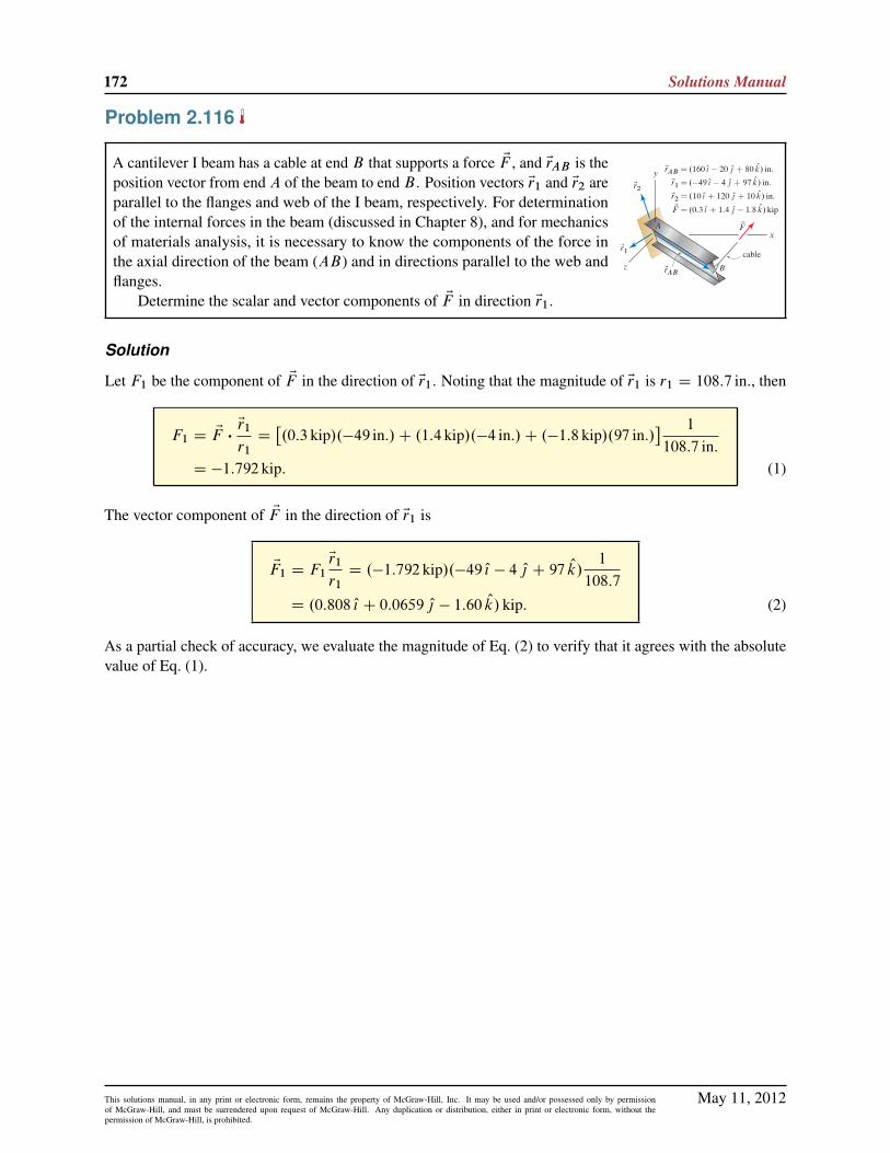
172 Solutions Manual
Problem 2.116
A cantilever I beam has a cable at end B that supports a force EF , and ErAB is theposition vector from end A of the beam to end B . Position vectors Er1 and Er2 areparallel to the flanges and web of the I beam, respectively. For determinationof the internal forces in the beam (discussed in Chapter 8), and for mechanicsof materials analysis, it is necessary to know the components of the force inthe axial direction of the beam (AB) and in directions parallel to the web andflanges.
Determine the scalar and vector components of EF in direction Er1.
Solution
Let F1 be the component of EF in the direction of Er1. Noting that the magnitude of Er1 is r1 D 108:7 in:, then
F1 D EF �Er1
r1D�.0:3 kip/.�49 in:/C .1:4 kip/.�4 in:/C .�1:8 kip/.97 in:/
� 1
108:7 in:D �1:792 kip: (1)
The vector component of EF in the direction of Er1 is
EF1 D F1Er1
r1D .�1:792 kip/.�49 O{ � 4 O| C 97 Ok/
1
108:7
D .0:808 O{ C 0:0659 O| � 1:60 Ok/ kip: (2)
As a partial check of accuracy, we evaluate the magnitude of Eq. (2) to verify that it agrees with the absolutevalue of Eq. (1).
May 11, 2012This solutions manual, in any print or electronic form, remains the property of McGraw-Hill, Inc. It may be used and/or possessed only by permissionof McGraw-Hill, and must be surrendered upon request of McGraw-Hill. Any duplication or distribution, either in print or electronic form, without thepermission of McGraw-Hill, is prohibited.

Statics 2e 173
Problem 2.117
A cantilever I beam has a cable at end B that supports a force EF , and ErAB is theposition vector from end A of the beam to end B . Position vectors Er1 and Er2 areparallel to the flanges and web of the I beam, respectively. For determinationof the internal forces in the beam (discussed in Chapter 8), and for mechanicsof materials analysis, it is necessary to know the components of the force inthe axial direction of the beam (AB) and in directions parallel to the web andflanges.
Determine the scalar and vector components of EF in direction Er2.
Solution
Let F2 be the component of EF in the direction of Er2. Noting that the magnitude of Er2 is r2 D 120:8 in:, then
F2 D EF �Er2
r2D�.0:3 kip/.10 in:/C .1:4 kip/.120 in:/C .�1:8 kip/.10 in:/
� 1
120:8 in:D 1:266 kip: (1)
The vector component of EF in the direction of Er2 is
EF2 D F2Er2
r2D .1:266 kip/.10 O{ C 120 O| C 10 Ok/
1
120:8
D .0:105 O{ C 1:26 O| C 0:105 Ok/ kip: (2)
As a partial check of accuracy, we evaluate the magnitude of Eq. (2) to verify that it agrees with the absolutevalue of Eq. (1).
May 11, 2012This solutions manual, in any print or electronic form, remains the property of McGraw-Hill, Inc. It may be used and/or possessed only by permissionof McGraw-Hill, and must be surrendered upon request of McGraw-Hill. Any duplication or distribution, either in print or electronic form, without thepermission of McGraw-Hill, is prohibited.

174 Solutions Manual
Problem 2.118
The gearshift lever AB for the transmission of a sports car has position vector Erwhose line of action passes through points A and B . The driver applies a forceEF to the knob of the lever to shift gears. If the component of EF perpendicular
to the gearshift lever must be 5N to shift gears, determine the magnitude F ofthe force.
Solution
Our strategy will be to use the dot product to determine the component of EF that is parallel to Er , namelyFk. We will then use the Pythagorean theorem to determine the component of EF that is perpendicular to Er ,namely F?. According to the problem statement, F? D 5N, which will allow us to solve for the value of F .
Noting that the magnitude of Er is r D 15mm, the component of EF that is parallel to Er is
Fk D EF �Er
rD F
�1
11
�.9 O{ � 6 O| � 3 Ok/ �
�5 O{ C 2 O| C 14 Ok
15(1)
DF
165
h.9/.�5/C .�6/.2/C .�2/.14/
i(2)
D F��85
165
�: (3)
The parallel and perpendicular components of EF are related by the Pythagorean theorem, F 2 D F 2kC F 2
?.
Rearranging this and noting that the perpendicular component F? D 5N, we obtain
F 2? D F
2� F 2k
(4)
.5N/2 D F 2�
hF��85
165
�i2(5)
.5N/2 D F 2.0:7346/: (6)
Solving Eq. (6) provides
F D 5:83N: (7)
May 11, 2012This solutions manual, in any print or electronic form, remains the property of McGraw-Hill, Inc. It may be used and/or possessed only by permissionof McGraw-Hill, and must be surrendered upon request of McGraw-Hill. Any duplication or distribution, either in print or electronic form, without thepermission of McGraw-Hill, is prohibited.

Statics 2e 175
Problem 2.119
A force of magnitude 8 lb is applied to line AB of a fishing rod OA. Determinethe vector components of the 8 lb force in directions parallel and perpendicularto the rod.
Solution
The position vector describing the direction of fishing rod OA is ErOA, and the magnitude of this vector isrOA, as follows
ErOA D .30 O| C 40 Ok/ in.; rOA D
q.30/2 C .40/2 in. D 50 in: (1)
The force EFAB is expressed as
EFAB D .8 lb/ErAB
rABD .8 lb/
.60 O{ C 120 O| � 40 Ok/ in.p.60/2 C .120/2 C .�40/2 in.
D .3:429 O{ C 6:857 O| � 2:286 Ok/ lb: (2)
The parallel component of the force is given by
Fk D EFAB �ErOA
rOAD
�.3:429/.0/C .6:857/.30/C .�2:286/.40/
�in.�lb
50 in:D 2:286 lb (3)
The perpendicular component is then
F? DqF 2
AB � F2kD
q.8 lb/2 � .2:286 lb/2 D 7:667 lb: (4)
The vector component of the force parallel to the rod is given by
EFk D FkErOA
rOAD .2:286 lb/
.30 O| C 40 Ok/ in.50 in:
D .1:372 O| C 1:829 Ok/ lb: (5)
The vector component of the force perpendicular to the rod is determined using EFAB DEFk C EF?, which
after rearrangement gives
EF? D EFAB �EFk D .3:429 O{ C 6:857 O| � 2:286 Ok/ lb � .1:372 O| C 1:829 Ok/ lb
D .3:429 O| C 5:485 O| � 4:114 Ok/ lb (6)
As a partial check of the accuracy of our answers, we may evaluate the magnitudes of EFk and EF? in Eqs. (5)and (6) to verify that they agree with Eqs. (3) and (4), respectively.
May 11, 2012This solutions manual, in any print or electronic form, remains the property of McGraw-Hill, Inc. It may be used and/or possessed only by permissionof McGraw-Hill, and must be surrendered upon request of McGraw-Hill. Any duplication or distribution, either in print or electronic form, without thepermission of McGraw-Hill, is prohibited.

176 Solutions Manual
Problem 2.120
Rod AB is the firing pin for the right-hand barrel of a side-by-side shotgun.During firing, end A is struck by the hammer, which imparts a force F to thefiring pin. The force F lies in a plane parallel to the xy plane, but the firing pinhas a three-dimensional orientation as shown. Determine the components of Fin directions parallel and perpendicular to the firing pin.
Solution
The coordinates of points A and B are A .1:1; 0:2;�0:2/ in., and B .0; 0:6;�0:6/ in.. Thus, the positionvector from A to B is given by
ErAB D�.0 � 1:1/ O{ C .0:6 � 0:2/ O| C .�0:6 � .�0:2// Ok
�in. D .�1:1 O{ C 0:4 O| � 0:4 Ok/ in.; (1)
and the magnitude of this vector is
rAB D
q.�1:1 in:/2 C .0:4 in:/2 C .�0:4 in:/2 D 1:237 in: (2)
The vector expression for the force EF applied to the firing pin is
EF D F.� cos 28ı O{ C sin 28ı O|/: (3)
The parallel component of the force is given by
Fk D EF �ErAB
rABD F
.� cos 28ı/.�1:1 in:/C .sin 28ı/.0:4 in:/C .0/.�0:4 in:/1:237 in:
D .0:9370/F; (4)
while the perpendicular component is
F? DqF 2 � F 2
kD
qF 2 �
�.0:9370/F
�2D .0:349/F: (5)
May 11, 2012This solutions manual, in any print or electronic form, remains the property of McGraw-Hill, Inc. It may be used and/or possessed only by permissionof McGraw-Hill, and must be surrendered upon request of McGraw-Hill. Any duplication or distribution, either in print or electronic form, without thepermission of McGraw-Hill, is prohibited.

Statics 2e 177
Problem 2.121
The collar C is fixed to rod AB and supports a weight W D 15N, acting in thenegative ´ direction. Determine the vector components of the weight that areparallel and perpendicular to rod AB .
Solution
The vector expression for the weight is EW D �15 Ok N. The position vector from A to B is denoted by ErAB ,such that
ErAB D .40 O{ C 40 O| � 70 Ok/ cm; rAB D
q402 C 402 C .�70/2 cm D 90 cm: (1)
The scalar component of EW parallel to ErAB is
Wk D EW �ErAB
rABD0C 0C .�15N/.�70 cm/
90 cmD 11:67N: (2)
Although W? is not asked for in this problem, determining it will provide a check of accuracy for our resultsfor EW?. Thus, the perpendicular component is
W? DqW 2 �W 2
kD
q.�15N/2 � .11:67N/2 D 9:428N: (3)
The parallel component of EW in vector form is then
EWk D WkErAB
rABD .11:67N/
.40 O{ C 40 O| � 70 Ok/ cm90 cm
D .5:19 O{ C 5:19 O| � 9:07 Ok/N: (4)
The perpendicular vector component is
EW? D EW � EWk D .�15N/ Ok � .5:185 O{ C 5:185 O| � 9:04 Ok/N D .�5:19 O{ � 5:19 O{ � 5:93 Ok/N:
(5)As a partial check of the accuracy of our results, we use Eqs. (4) and (5) to evaluate the magnitudes Wk andW? as
Wk D
q.5:185/2 C .5:185/2 C .�9:074/2 N D 11:67N; (6)
W? D
q.�5:185/2 C .�5:185/2 C .�5:926/2 N D 9:428N; (7)
which agree with the values reported in Eqs. (2) and (3).
May 11, 2012This solutions manual, in any print or electronic form, remains the property of McGraw-Hill, Inc. It may be used and/or possessed only by permissionof McGraw-Hill, and must be surrendered upon request of McGraw-Hill. Any duplication or distribution, either in print or electronic form, without thepermission of McGraw-Hill, is prohibited.

178 Solutions Manual
Problem 2.122
The collar C is fixed to rod AB using a glued bond that allows a maximumforce of 35N parallel to the axis of the rod. The collar has weight W acting inthe negative ´ direction. Determine the weight W of the collar that will causethe glued bond to break.
Solution
The vector expression for the weight is EW D �W Ok. The position vector from A to B is denoted by ErAB ,such that
ErAB D .40 O{ C 40 O| � 70 Ok/ cm; rAB D
q402 C 402 C .�70/2 cm D 90 cm: (1)
Since the maximum force in the AB direction is 35N, it follows that
Wk D 35N D EW �ErAB
rABD0C 0C .�W /.�70 cm/
90 cm: (2)
Solving the above equation provides
W D .90=70/35N D 45:0N: (3)
May 11, 2012This solutions manual, in any print or electronic form, remains the property of McGraw-Hill, Inc. It may be used and/or possessed only by permissionof McGraw-Hill, and must be surrendered upon request of McGraw-Hill. Any duplication or distribution, either in print or electronic form, without thepermission of McGraw-Hill, is prohibited.

Statics 2e 179
Problem 2.123
Components of a machine (not shown in the figure) are actuated by motion of athreaded collar C that slides on a fixed barDEFGHI . SegmentDE of the baris straight and vertical, segment FG is straight where the coordinated of pointsF and G are given in the figure, and segment HI is straight and horizontal.The collar’s motion is controlled by screw AB , which is turned by the motor atpoint A. If the force in the screw is 50N compression, use the dot product todetermine the component of the screw force in the direction of the bar for thepositions of the collar given below. Also determine the component of the screwforce perpendicular to the bar.
(a) Collar C is 2mm below point E.
(b) Collar C is 1/3 the distance from point F to point G.
Solution
Part (a) When collar C is 2 mm below point E, then
ErAC D .60 O{ C 13 O|/mm; (1)
EFAC D 50 NErAC
rACD 50 N
60 O{ C 13 O|p.60/2 C .13/2
D .48:87 O{ C 10:59 O|/N: (2)
The component of the screw force in the direction of the bar from point D to point E, which is the Cydirection, is simply the y component of Eq. (2), which provides
Fk D 10:59 N: (3)
To obtain this result more formally, we take the dot product of Eq. (2) with a unit vector in the direction fromD to E, namely O|; to obtain
Fk D EFAC � O| D .48:87 N/.0/C .10:59 N/.1/ D 10:59 N: (4)
The component of the screw force in the direction perpendicular to the bar is
F? DqF 2 � F 2
kD
q.50 N/2 � .10:59 N/2 D 48:87 N. (5)
Part (b) When collar C is 1=3 the distance from point F to point G, the coordinates of C are equal to thecoordinates of F plus 1=3 of the difference between the coordinates of points G and F . Hence
xC D 65 mmC1
3.89 mm � 65 mm/ D 73 mm; (6)
yC D 25 mmC1
3.70 mm � 25 mm/ D 40 mm: (7)
May 11, 2012This solutions manual, in any print or electronic form, remains the property of McGraw-Hill, Inc. It may be used and/or possessed only by permissionof McGraw-Hill, and must be surrendered upon request of McGraw-Hill. Any duplication or distribution, either in print or electronic form, without thepermission of McGraw-Hill, is prohibited.

180 Solutions Manual
ThusErAC D .73 O{ C 40 O|/mm; (8)
EFAC D 50 NErAC
rACD 50 N
73 O{ C 40 O|p.73/2 C .40/2
D .43:85 O{ C 24:03 O|/N: (9)
The position vector from F to G is
ErFG D Œ.89 � 65/ O{ C .70 � 25/ O|�mm D .24 O{ C 45 O|/mm: (10)
The component of the screw force in the direction of the bar from point F to point G is
Fk D EFAC �ErFG
rFGD.43:85 N/.24 mm/C .24:03 N/.45 mm/p
.24 mm/2 C .45 mm/2D 41:83 N: (11)
The component of the screw force in the direction perpendicular to the bar is
F? DqF 2 � F 2
kD
q.50 N/2 � .41:83 N/2 D 27:38 N: (12)
May 11, 2012This solutions manual, in any print or electronic form, remains the property of McGraw-Hill, Inc. It may be used and/or possessed only by permissionof McGraw-Hill, and must be surrendered upon request of McGraw-Hill. Any duplication or distribution, either in print or electronic form, without thepermission of McGraw-Hill, is prohibited.
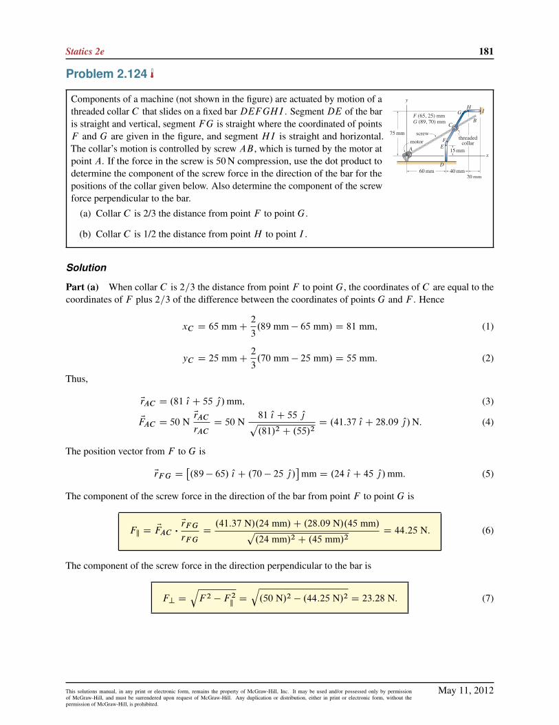
Statics 2e 181
Problem 2.124
Components of a machine (not shown in the figure) are actuated by motion of athreaded collar C that slides on a fixed barDEFGHI . SegmentDE of the baris straight and vertical, segment FG is straight where the coordinated of pointsF and G are given in the figure, and segment HI is straight and horizontal.The collar’s motion is controlled by screw AB , which is turned by the motor atpoint A. If the force in the screw is 50N compression, use the dot product todetermine the component of the screw force in the direction of the bar for thepositions of the collar given below. Also determine the component of the screwforce perpendicular to the bar.
(a) Collar C is 2/3 the distance from point F to point G.
(b) Collar C is 1/2 the distance from point H to point I .
Solution
Part (a) When collar C is 2=3 the distance from point F to point G, the coordinates of C are equal to thecoordinates of F plus 2=3 of the difference between the coordinates of points G and F . Hence
xC D 65 mmC2
3.89 mm � 65 mm/ D 81 mm; (1)
yC D 25 mmC2
3.70 mm � 25 mm/ D 55 mm: (2)
Thus,
ErAC D .81 O{ C 55 O|/mm; (3)
EFAC D 50 NErAC
rACD 50 N
81 O{ C 55 O|p.81/2 C .55/2
D .41:37 O{ C 28:09 O|/N. (4)
The position vector from F to G is
ErF G D�.89 � 65/ O{ C .70 � 25 O|/
�mm D .24 O{ C 45 O|/mm: (5)
The component of the screw force in the direction of the bar from point F to point G is
Fk D EFAC �ErF G
rF GD.41:37 N/.24 mm/C .28:09 N/.45 mm/p
.24 mm/2 C .45 mm/2D 44:25 N: (6)
The component of the screw force in the direction perpendicular to the bar is
F? DqF 2 � F 2
kD
q.50 N/2 � .44:25 N/2 D 23:28 N: (7)
May 11, 2012This solutions manual, in any print or electronic form, remains the property of McGraw-Hill, Inc. It may be used and/or possessed only by permissionof McGraw-Hill, and must be surrendered upon request of McGraw-Hill. Any duplication or distribution, either in print or electronic form, without thepermission of McGraw-Hill, is prohibited.

182 Solutions Manual
Part (b) When collar C is 1=2 the distance from point H to point I , then
ErAC D .110 O{ C 75 O|/mm; (8)
EFAC D 50 NErAC
rACD 50 N
110 O{ C 75 O|p.110/2 C .75/2
D .41:31 O{ C 28:17 O|/N: (9)
The component of the screw force in the direction of the bar from point H to point I , which is the Cxdirection, is simply the x component of Eq. (9), which provides
Fk D 41:31 N: (10)
To obtain this result more formally, we take the dot product of Eq. (9) with a unit vector in the direction fromH to I , namely O{, to obtain
Fk D EFAC � O{ D .41:31 N/.1/C .28:17 N/.0/ D 41:31 N: (11)
The component of the screw force in the direction perpendicular to the bar is
F? DqF 2 � F 2
kD
q.50 N/2 � .41:31 N/2 D 28:17 N. (12)
May 11, 2012This solutions manual, in any print or electronic form, remains the property of McGraw-Hill, Inc. It may be used and/or possessed only by permissionof McGraw-Hill, and must be surrendered upon request of McGraw-Hill. Any duplication or distribution, either in print or electronic form, without thepermission of McGraw-Hill, is prohibited.

Statics 2e 183
Problem 2.125
Components of a machine (not shown in the figure) are actuated by motion of athreaded collar C that slides on a fixed barDEFGHI . SegmentDE of the baris straight and vertical, segment FG is straight where the coordinated of pointsF and G are given in the figure, and segment HI is straight and horizontal.The collar’s motion is controlled by screw AB , which is turned by the motor atpoint A. If the force in the screw is 50N compression, use the dot product todetermine the component of the screw force in the direction of the bar for thepositions of the collar given below. Also determine the component of the screwforce perpendicular to the bar.
Let the collar be positioned on the straight segment of the bar between pointsF and G. Determine the point along this segment of the bar where the forcefrom the screw in the direction of the bar is largest, and determine the value ofthis force. Also determine the component of the screw force perpendicular tothe bar.
Solution
The component of the screw force in the direction of the bar from point F to point G will be greatest whenthe angle between EFAC (which is parallel to ErAC ) and ErF G is smallest. Thus, by inspection, this occurswhen the collar C is positioned at point G. Thus,
ErAC D ErAG D .89 O{ C 70 O|/mm; (1)
EFAC D 50 NErAC
rACD 50 N
89 O{ C 70 O|p.89/2 C .70/2
D .39:30 O{ C 30:91 O|/ N: (2)
The position vector from point F to point G is
ErF G D�.89 � 65/ O{ C .70 � 25 O|/
�mm D .24 O{ C 45 O|/mm: (3)
The component of the screw force in the direction from point F to point G is
Fk D EFAC �ErF G
rF GD.39:03 N/.24 mm/C .30:91 N/.45 mm/p
.24 mm/2 C .45 mm/2D 45:77 N: (4)
The component of the screw force perpendicular to the bar is
F? DqF 2 � F 2
kD
q.50 N/2 � .45:77 N/2 D 20:13 N: (5)
May 11, 2012This solutions manual, in any print or electronic form, remains the property of McGraw-Hill, Inc. It may be used and/or possessed only by permissionof McGraw-Hill, and must be surrendered upon request of McGraw-Hill. Any duplication or distribution, either in print or electronic form, without thepermission of McGraw-Hill, is prohibited.

184 Solutions Manual
Problem 2.126
A winch at point B is used to slide a box up a chute CD in a warehouse. If thecomponent of the force from cable AB in the direction of the chute must be400 lb, determine the force in the cable for the position of the box given below.The chute is parallel to the x´ plane. Neglect the size of the box and the winch.
The box is at the base of the chute, point C .
Solution
When the box A is at the base of the chute, point C , then
ErAB D .�165 O{ � 100 O| C 130 Ok/ in.; (1)
EFAB D FABErAB
rABD FAB
�165 O{ � 100 O| C 130 Ok
232:6: (2)
The position vector from point C to D of the chute is
ErCD D .�120 O{ C 50 Ok/ in. (3)
The component of EFAB in the direction of the chute must be 400 lb, hence
Fk D EFAB �ErCD
rCDD 400 lb (4)
FAB�165 O{ � 100 O| C 130 Ok
232:6�.�120 O{ C 50 Ok/ in.
130 in.D 400 lb (5)
FAB.�165/.�120/C .�100/.0/C .130/.50/
.232:6/.130/D 400 lb: (6)
Thus, the force in the cable must be
FAB D 460:0 lb. (7)
May 11, 2012This solutions manual, in any print or electronic form, remains the property of McGraw-Hill, Inc. It may be used and/or possessed only by permissionof McGraw-Hill, and must be surrendered upon request of McGraw-Hill. Any duplication or distribution, either in print or electronic form, without thepermission of McGraw-Hill, is prohibited.

Statics 2e 185
Problem 2.127
A winch at point B is used to slide a box up a chute CD in a warehouse. If thecomponent of the force from cable AB in the direction of the chute must be400 lb, determine the force in the cable for the position of the box given below.The chute is parallel to the x´ plane. Neglect the size of the box and the winch.
The box is 1/3 the distance up the chute from point C .
Solution
When box A is 1=3 the distance up the chute from point C , then the coordinates of box A are
xA D 120 in. �1
3.120 in./ D 80 in.; (1)
yA D 100 in.; (2)
´A D1
3.50 in./ D 16:67 in. (3)
Then
ErAB D�.�45 � 80/ O{ C .0 � 100/ O| C .130 � 16:67/ Ok
�in. (4)
D .�125 O{ � 100 O| C 113:3 Ok/ in.; (5)
EFAB D FABErAB
rABD FAB
�125 O{ � 100 O| C 113:3 Ok
196:1: (6)
The position vector from point C to D of the chute is
ErCD D .�120 O{ C 50 Ok/ in. (7)
The component of EFAB in the direction of the chute must be 400 lb, hence
Fk D EFAB �ErCD
rCDD 400 lb (8)
FAB�125 O{ � 100 O| C 113:3 Ok
196:1�.�120 O{ C 50 Ok/ in.
130 in.D 400 lb (9)
FAB.�125/.�120/C .�100/.0/C .113:3/.50/
.196:1/.130/D 400 lb: (10)
Thus, the force in the cable must be
FAB D 493:5 lb: (11)
May 11, 2012This solutions manual, in any print or electronic form, remains the property of McGraw-Hill, Inc. It may be used and/or possessed only by permissionof McGraw-Hill, and must be surrendered upon request of McGraw-Hill. Any duplication or distribution, either in print or electronic form, without thepermission of McGraw-Hill, is prohibited.

186 Solutions Manual
Problem 2.128
A winch at point B is used to slide a box up a chute CD in a warehouse. If thecomponent of the force from cable AB in the direction of the chute must be400 lb, determine the force in the cable for the position of the box given below.The chute is parallel to the x´ plane. Neglect the size of the box and the winch.
The box is 3/4 the distance up the chute from point C .
Solution
When box A is 3=4 the distance up the chute from point C; then the coordinates of the box A are
xA D 120 in. �3
4.120 in./ D 30 in.; (1)
yA D 100 in.; (2)
´A D3
4.50 in./ D 37:5 in. (3)
Then
ErAB D Œ.�45 � 30/ O{ C .0 � 100/ O| C .130 � 37:5/ Ok� in. (4)
D .�75 O{ � 100 O| C 92:5 Ok/ in.; (5)
EFAB D FABErAB
rABD FAB
�75 O{ � 100 O| C 92:5 Ok
155:5: (6)
The position vector from point C to D of the chute is
ErCD D .�120 O{ C 50 Ok/ in. (7)
The component of EFAB in the direction of the chute must be 400 lb, hence
Fk D EFAB �ErCD
rCDD 400 lb (8)
FAB�75 O{ � 100 O| C 92:5 Ok
155:5�.�120 O{ C 50 Ok/ in.
130 in.D 400 lb (9)
FAB.�75/.�120/C .�100/.0/C .92:5/.50/
.155:5/.130/D 400 lb: (10)
Thus, the force in the cable must be
FAB D 593:5 lb: (11)
May 11, 2012This solutions manual, in any print or electronic form, remains the property of McGraw-Hill, Inc. It may be used and/or possessed only by permissionof McGraw-Hill, and must be surrendered upon request of McGraw-Hill. Any duplication or distribution, either in print or electronic form, without thepermission of McGraw-Hill, is prohibited.
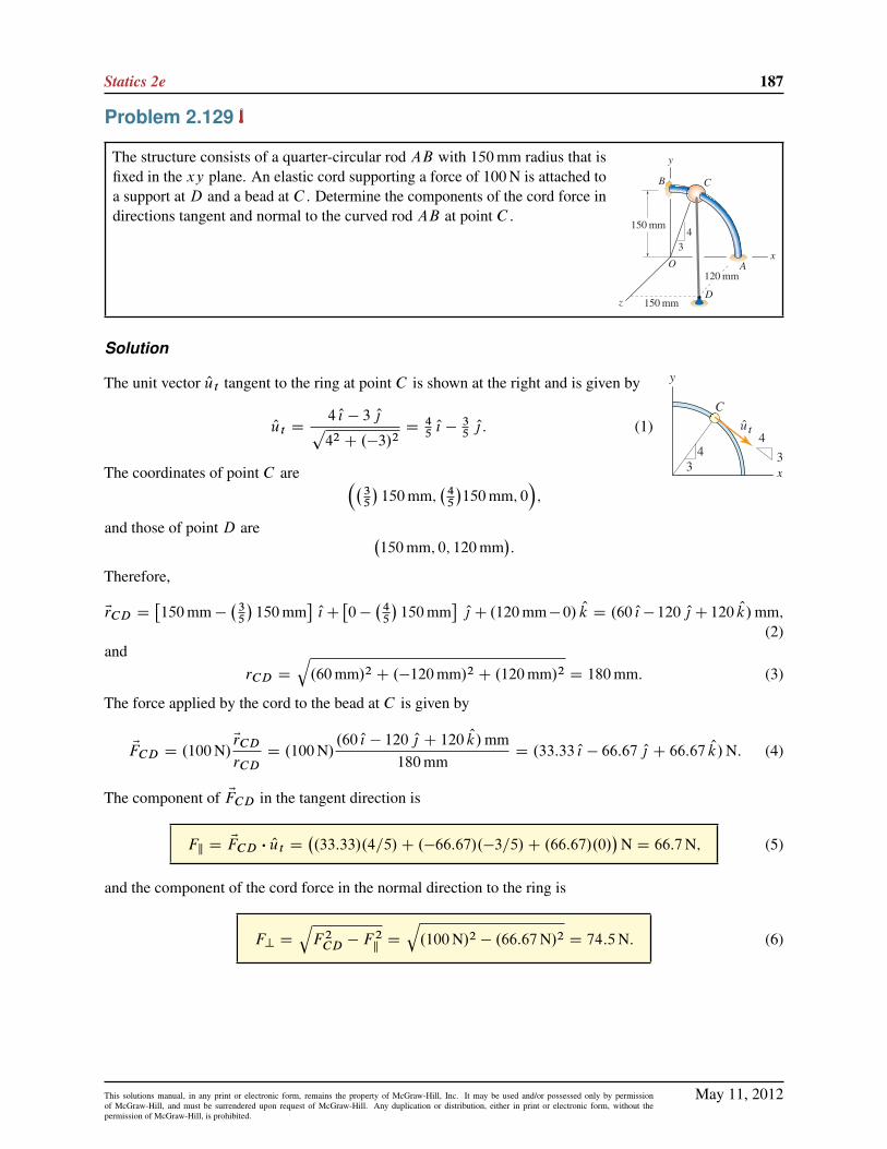
Statics 2e 187
Problem 2.129
The structure consists of a quarter-circular rod AB with 150mm radius that isfixed in the xy plane. An elastic cord supporting a force of 100N is attached toa support at D and a bead at C . Determine the components of the cord force indirections tangent and normal to the curved rod AB at point C .
Solution
The unit vector Out tangent to the ring at point C is shown at the right and is given by
Out D4 O{ � 3 O|p42 C .�3/2
D45O{ � 3
5O| : (1)
The coordinates of point C are ��35
�150mm;
�45
�150mm; 0
�;
and those of point D are �150mm; 0; 120mm
�:
Therefore,
ErCD D�150mm �
�35
�150mm
�O{C
�0 �
�45
�150mm
�O| C .120mm� 0/ Ok D .60 O{� 120 O| C 120 Ok/mm;
(2)and
rCD D
q.60mm/2 C .�120mm/2 C .120mm/2 D 180mm: (3)
The force applied by the cord to the bead at C is given by
EFCD D .100N/ErCD
rCDD .100N/
.60 O{ � 120 O| C 120 Ok/mm180mm
D .33:33 O{ � 66:67 O| C 66:67 Ok/N: (4)
The component of EFCD in the tangent direction is
Fk D EFCD � Out D�.33:33/.4=5/C .�66:67/.�3=5/C .66:67/.0/
�N D 66:7N; (5)
and the component of the cord force in the normal direction to the ring is
F? DqF 2
CD � F2kD
q.100N/2 � .66:67N/2 D 74:5N: (6)
May 11, 2012This solutions manual, in any print or electronic form, remains the property of McGraw-Hill, Inc. It may be used and/or possessed only by permissionof McGraw-Hill, and must be surrendered upon request of McGraw-Hill. Any duplication or distribution, either in print or electronic form, without thepermission of McGraw-Hill, is prohibited.

188 Solutions Manual
Problem 2.130
Bead A has negligible weight and slides without friction on rigid fixed bar BC .An elastic cord AD, which supports a 10 lb tensile force, is attached to thebead. At the instant shown, the bead has zero velocity. For the position of thebead given below, determine the vector components of the cord tension that actparallel and perpendicular to direction BC of the bar (your answers should bevectors). Due to the cord tension, will the bead slide toward point B or C ?
Bead A is positioned halfway between points B and C .
Solution
ErBC D .12 O{ � 4 O| C 6 Ok/ in.; rBC D 14 in. (1)
When bead A is positioned half way between points B and C ,
ErBA D .6 O{ � 2 O| C 3 Ok/ in. (2)
While we could write an expression for ErAD by taking the difference of the coordinates of D (head of vector)and A (tail of vector), we will use the following vector addition instead
ErAD D ErAB„ƒ‚…�ErBA
CErBO C ErOD (3)
D.�6 O{ C 2 O| � 3 Ok/ in.C .0 O{ � 4 O| � 13 Ok/ in.C .8 O{ C 10 O| C 0 Ok/ in. (4)
D.2 O{ C 8 O| � 16 Ok/ in.; (5)
rAD D18 in.; (6)
ETAD D10 lbErAD
rADD 10 lb
2 O{ C 8 O| � 16 Ok
18: (7)
The component and vector component of ETAD parallel to rod BC is
Tk D ETAD �ErBC
rBCD10 lb
�.2/.12/C .8/.�4/C .�16/.6/
�.18/.14/
D �4:127 lb; (8)
ETk D TkErBC
rBCD .�4:127 lb)
12 O{ � 4 O| C 6 Ok14
(9)
D .�3:537 O{ C 1:179 O| � 1:769 Ok/ lb. (10)
The vector component of ETAD perpendicular to rod BC is
ET? D ETAD �ETk D .4:648 O{ C 3:265 O| � 7:120 Ok/ lb: (11)
As a partial check of accuracy, we evaluate the magnitude of Eq. (11) to obtain T? D 9:108 lb, and thenusing Tk D �4:127 lb, we evaluate
qT 2kC T 2?
to verify that the result is 10 lb.
Sliding direction Since Tk is negative, the projection of ETAD in the BC direction is from C to B . Hence,
The bead will tend to slide toward B due to the cord force.
May 11, 2012This solutions manual, in any print or electronic form, remains the property of McGraw-Hill, Inc. It may be used and/or possessed only by permissionof McGraw-Hill, and must be surrendered upon request of McGraw-Hill. Any duplication or distribution, either in print or electronic form, without thepermission of McGraw-Hill, is prohibited.

Statics 2e 189
Problem 2.131
Bead A has negligible weight and slides without friction on rigid fixed bar BC .An elastic cord AD, which supports a 10 lb tensile force, is attached to thebead. At the instant shown, the bead has zero velocity. For the position of thebead given below, determine the vector components of the cord tension that actparallel and perpendicular to direction BC of the bar (your answers should bevectors). Due to the cord tension, will the bead slide toward point B or C ?
Bead A is 1/4 the distance from point B to point C .
Solution
ErBC D .12 O{ � 4 O| C 6 Ok/ in.; rBC D 14 in. (1)
When bead A is positioned 1=4 the distance from point B to point C ,
ErBA D .3 O{ � O| C 1:5 Ok/ in. (2)
While we could write an expression for ErAD by taking the difference of the coordinates of D (head of vector)and A (tail of vector), we will use the following vector addition instead
ErAD D ErAB„ƒ‚…�ErBA
C ErBO C ErOD (3)
D .�3 O{ C O| � 1:5 Ok/ in.C .0 O{ � 4 O| � 13 Ok/ in.C .8 O{ C 10 O| C 0 Ok/ in. (4)
D .5 O{ C 7 O| � 14:5 Ok/ in.; (5)
ETAD D 10 lbErAD
rADD 10 lb
5 O{ C 7 O| � 14:5 Ok
16:86: (6)
The component and vector component of ETAD parallel to rod BC is
Tk D ETAD �ErBC
rBCD10 lb
�.5/.12/C .7/.�4/C .�14:5/.6/
�.16:86/.14/
D �2:330 lb; (7)
ETk D TkErBC
rBCD .�2:330 lb/
12 O{ � 4 O| C 6 Ok
14(8)
D ( � 1.997 O{ C 0.6658 O| � 0.9986 Ok) lb. (9)
The vector component of ETAD perpendicular to rod BC is
ET? D ETAD �ETk D .4:963 O{ C 3:486 O| � 7:602 Ok/ lb: (10)
As a partial check of accuracy, we evaluate the magnitude of Eq. (10) to obtain T? D 9:725 lb, and thenusing Tk D �2:330 lb, we evaluate
qT 2kC T 2?
to verify that the result is 10 lb.
Sliding direction Since Tk is negative, the projection of ETAD in the BC direction is from C to B . Hence,
The bead will tend to slide toward B due to the cord force.
May 11, 2012This solutions manual, in any print or electronic form, remains the property of McGraw-Hill, Inc. It may be used and/or possessed only by permissionof McGraw-Hill, and must be surrendered upon request of McGraw-Hill. Any duplication or distribution, either in print or electronic form, without thepermission of McGraw-Hill, is prohibited.

190 Solutions Manual
Problem 2.132
Bead B has negligible weight and slides without friction on rigid fixed bar AC .An elastic cord BD, which supports a 60N tensile force, is attached to the bead.At the instant shown, the bead has zero velocity. For the position of the beadgiven below, determine the components of the cord tension that act parallel andperpendicular to direction AC of the bar. Due to the cord tension, will the beadslide toward point A or C ?
Bead B is positioned halfway between points A and C .
Solution
The position vector from A to C is
ErAC D .�120 O{ C 60 O| C 40 Ok/mm; rAC D
q.�120/2 C 602 C 402 mm D 140mm: (1)
Since B is at the midpoint of AC , it follows that the position vector from A to B is
ErAB D
�140mm2
�.�120 O{ C 60 O| C 40 Ok/mm
140mmD .�60 O{ C 30 O| C 20 Ok/mm: (2)
The position vector from A to D is given by ErAD D .�60 O{ C 60 Ok/mm. The position vector from D to B ,ErBD , may be determined using
ErBD D ErBA C ErAD
D �ErAB C ErAD
D �.�60 O{ C 30 O| C 20 Ok/mmC .�60 O{ C 60 Ok/mm
D .�30 O| C 40 Ok/mm: (3)
The vector expression for the 60N tensile force the cord applies to bead B is
EFBD D .60N/.�30 O| C 40 Ok/mmp.�30/2 C .40/2 mm
D .�36 O| C 48 Ok/N: (4)
The component of the cord tension parallel to AC is given by
Fk D EFBD �ErAC
rACD.�36 O| C 48 Ok/N � .�120 O{ C 60 O| C 40 Ok/mm
140mmD �1:71N: (5)
The perpendicular component of the cord tension is
F? DqF 2
BD � F2kD
q.60N/2 � .�1:714N/2 D 59:98N: (6)
Since the value of Fk found in Eq. (5) is negative, the component of the cord force is actually in the direction
opposite ErAC , and hence is in the direction from C to A. Thus, the bead slides toward A.
May 11, 2012This solutions manual, in any print or electronic form, remains the property of McGraw-Hill, Inc. It may be used and/or possessed only by permissionof McGraw-Hill, and must be surrendered upon request of McGraw-Hill. Any duplication or distribution, either in print or electronic form, without thepermission of McGraw-Hill, is prohibited.

Statics 2e 191
Problem 2.133
Bead B has negligible weight and slides without friction on rigid fixed bar AC .An elastic cord BD, which supports a 60N tensile force, is attached to the bead.At the instant shown, the bead has zero velocity. For the position of the beadgiven below, determine the components of the cord tension that act parallel andperpendicular to direction AC of the bar. Due to the cord tension, will the beadslide toward point A or C ?
Bead B is 2/5 the distance from point A to point C .
Solution
The position vector from A to C is
ErAC D .�120 O{ C 60 O| C 40 Ok/mm, rAC D
q.�120/2 C .60/2 C .40/2 mm D 140 mm. (1)
Since B is 2=5 the distance from point A to C , it follows that the position vector from A to bead B is
ErAB D2
5.�120 O{ C 60 O| C 40 Ok/mm D .�48 O{ C 24 O| C 16 Ok/mm: (2)
The position vector from A to D is ErAD D .�60 O{ C 60 Ok/mm. The position vector from D to bead B is
ErBD D ErBA C ErAD
D � ErAB C ErAD
D �.�48 O{ C 24 O| C 16 Ok/mmC .�60 O{ C 0 O| C 60 Ok/mm
D .�12 O{ � 24 O| C 44 Ok/mm: (3)
The vector expression for the 60 N tensile force the cord applies to bead B is
EFBD D 60 NErBD
rBDD 60 N
�12 O{ � 24 O| C 44 Okp.�12/2 C .�24/2 C .44/2
D .�13:97 O{ � 27:94 O| C 51:23 Ok/N: (4)
The component of the cord force parallel to AC is
Fk D EFBD �ErAC
rACD.�13:97 N/.�120 mm/C .�27:94N/.60 mm/C .51:23 N/.40 mm/
140 mmD 14:64 N.
(5)
The perpendicular component of the cord force is
F? DqF 2
BD � F2kD
q.60 N/2 � .14:64 N/2 D 58:19 N. (6)
Since the value of Fk found in Eq. (5) is positive, the component of the cord force is in the direction from A
to C: Thus, the bead will slide toward C .
May 11, 2012This solutions manual, in any print or electronic form, remains the property of McGraw-Hill, Inc. It may be used and/or possessed only by permissionof McGraw-Hill, and must be surrendered upon request of McGraw-Hill. Any duplication or distribution, either in print or electronic form, without thepermission of McGraw-Hill, is prohibited.

192 Solutions Manual
Problem 2.134
A sports car at point A drives down a straight stretch of road CD. A police carat point B uses radar to measure the speed of the car, and obtains a reading of80 km=h. For the position of the car given below, determine the speed of the car.Note that the 80 km=h speed measured by the radar gun is the rate of change ofthe distance between the car and the radar gun.
The car is 30% of the distance from point C to point D.
Solution
Let the actual speed of the car along the line from C to D be denoted by v, and then the vector representationof this (i.e., the velocity) is Ev D v.ErCD=rCD/: Using the coordinates of points C andD given in the problemstatement,
ErCD D
h�200 � .�150/
�O{ C
�400 � .�50/
�O| C .�10 � 30/ Ok
im
D .350 O{ C 450 O| � 40 Ok/m, (1)
Ev D vErCD
rCDD v
350 O{ C 450 O| � 40 Ok
571:5: (2)
When the car is positioned 30% of the distance from C to D, then the position vector from C to A is
ErCA D .0:3/ ErCD D .105 O{ C 135 O| � 12 Ok/m. (3)
Let s be the speed measured by the radar gun. This speed is the component of the car’s velocity Ev in thedirection AB. Hence
s D Ev �ErAB
rAB: (4)
The position vector ErAB may be determined using vector addition, as follows
ErAB D ErAC C ErCB (5)
D � ErCA C ErCB (6)
D �.105 O{ C 135 O| � 12 Ok/mCh�100 � .�150/
�O{ C
�600 � .�50/
�O| C .40 � 30/ Ok
im (7)
D �.105 O{ C 135 O| � 12 Ok/mC .250 O{ C 650 O| C 10 Ok/m (8)
D .145 O{ C 515 O| C 22 Ok/m; (9)
rAB D
q.145/2 C .515/2 C .22/2 m D 535:5 m: (10)
Evaluating Eq. (4) provides
s D v350 O{ C 450 O| � 40 Ok
571:5�145 O{ C 515 O| C 22 Ok
535:5(11)
D v.350/.145/C .450/.515/C .�40/.22/
.571:5/.535:5/: (12)
When the speed measured by the radar gun is s D 80 km=h, Eq. (12) may be solved to obtain the speed ofthe car as
v D 86:93 km=h: (13)
May 11, 2012This solutions manual, in any print or electronic form, remains the property of McGraw-Hill, Inc. It may be used and/or possessed only by permissionof McGraw-Hill, and must be surrendered upon request of McGraw-Hill. Any duplication or distribution, either in print or electronic form, without thepermission of McGraw-Hill, is prohibited.

Statics 2e 193
Problem 2.135
A sports car at point A drives down a straight stretch of road CD. A police carat point B uses radar to measure the speed of the car, and obtains a reading of80 km=h. For the position of the car given below, determine the speed of the car.Note that the 80 km=h speed measured by the radar gun is the rate of change ofthe distance between the car and the radar gun.
The car is 60% of the distance from point C to point D.
Solution
Let the actual speed of the car along the line from C to D be denoted by v, and then the vector representationof this (i.e., the velocity) is Ev D v.ErCD=rCD/. Using the coordinates of points C andD given in the problemstatement,
ErCD D
h�200 � .�150/
�O{ C
�400 � .�50/
�O| C .�10 � 30/ Ok
im
D .350 O{ C 450 O| � 40 Ok/m, (1)
Ev D vErCD
rCDD v
350 O{ C 450 O| � 40 Ok
571:5: (2)
When the car is positioned 60% of the distance from C to D, then the position vector from C to A is
ErCA D .0:6/ ErCD D .210 O{ C 270 O| � 24 Ok/m. (3)
Let s be the speed measured by the radar gun. This speed is the component of the car’s velocity Ev in thedirection AB. Hence
s D Ev �ErAB
rAB: (4)
The position vector ErAB may be determined using vector addition, as follows
ErAB D ErAC C ErCB (5)
D � ErCA C ErCB (6)
D �.210 O{ C 270 O| � 24 Ok/mCh�100 � .�150/
�O{ C
�600 � .�50/
�O| C .40 � 30/ Ok
im (7)
D �.210 O{ C 270 O| � 24 Ok/mC .250 O{ C 650 O| C 10 Ok/m (8)
D .40 O{ C 380 O| C 34 Ok/m; (9)
rAB D
q.40/2 C .380/2 C .34/2 m D 383:6m: (10)
Evaluating Eq. (4) provides
s D v350 O{ C 450 O| � 40 Ok
571:5�40 O{ C 380 O| C 34 Ok
383:6(11)
D v.350/.40/C .450/.380/C .�40/.34/
.571:5/.383:6/: (12)
When the speed measured by the radar gun is s D 80 km=h, Eq. (12) may be solved to obtain the speed ofthe car as
v D 95:50 km/h: (13)
May 11, 2012This solutions manual, in any print or electronic form, remains the property of McGraw-Hill, Inc. It may be used and/or possessed only by permissionof McGraw-Hill, and must be surrendered upon request of McGraw-Hill. Any duplication or distribution, either in print or electronic form, without thepermission of McGraw-Hill, is prohibited.

194 Solutions Manual
Problem 2.136
Let the road shown be straight between points C andD and beyond. Determinethe shortest distance between the police car at point B and the road. Determineif the point where the road is closest to the police car falls within segment CD,or outside of this.
Solution
Our strategy will be to write expressions for ErCB and ErCD . The component of ErCB that is perpendicular toErCD is the shortest distance between the road and police car, while the component of ErCB that is parallel toErCD will identify the point on the road where the road is closest to the police car. Using the coordinatesprovided in the problem statement, the following position vectors may be written
ErCB D
h�100 � .�150/
�O{ C
�600 � .�50/
�O| C .40 � 30/ Ok
im
D .250 O{ C 650 O| C 10 Ok/m; (1)
rCB D
q.250/2 C .650/2 C .10/2 m D 696:5 m, (2)
ErCD D
h�200 � .�150/
�O{ C
�400 � .�50/
�O| C .�10 � 30/ Ok
im
D .350 O{ C 450 O| � 40 Ok/m, (3)
rCD D
q.350/2 C .450/2 C .�40/2 m D 571:5 m. (4)
The component of ErCB that is parallel to ErCD is
rk D ErCB �ErCD
rCDD.250 m/.350 m/C .650 m/.450 m/C .10 m/.�40 m/
571:5 mD 664:2 m: (5)
Since the result in Eq. (5) is larger than the distance between points C and D (which is 571.5 m),
the point where the road is closest to the police car lies outside of segment CD of the road.
The component of ErCB that is perpendicular to ErCD is
r? Dqr2CB � r
2kD
q.696:5 m/2 � .664:2 m/2 D 209:5 m. (6)
Hence, the shortest distance between the police car and the road is 209.5 m.
May 11, 2012This solutions manual, in any print or electronic form, remains the property of McGraw-Hill, Inc. It may be used and/or possessed only by permissionof McGraw-Hill, and must be surrendered upon request of McGraw-Hill. Any duplication or distribution, either in print or electronic form, without thepermission of McGraw-Hill, is prohibited.

Statics 2e 195
Problem 2.137
The manager of a baseball team plans to use a radar gun positioned at point A tomeasure the speed of pitches for a right-handed pitcher. If the person operatingthe radar gun measures a speed s when the baseball is one-third the distancefrom the release point at B to the catcher’s glove at C , what is the actual speedof the pitch? Assume the pitch follows a straight-line path, and express youranswer in terms of s: Note that the value s measured by the radar gun is the rateof change of the distance between point A and the ball.
Solution
Let the actual speed of the ball along the line from B to C be denoted by v, and then the vector representationof this (i.e., the velocity) is Ev D v.ErBC =rBC /. Consider the point at which the speed is measured by theradar gun (one third of the distance from B to C ) to be denoted by point E. The value of speed measured bythe radar gun is then the component of the speed in the AE direction
s D Ev �ErAE
rAE: (1)
To evaluate Eq. (1), expressions for ErBC and ErAE , and their magnitudes rBC and rAE , must be determined.Since the coordinates of points B and C are given, we may write
ErBC D˚Œ.�3/ � .40/� O{ C Œ.�3/ � .42/� O| C Œ.3/ � .5/� Ok
ft D .�43 O{ � 45 O| � 2 Ok/ ft; (2)
rBC D
q.�43 ft/2 C .�45 ft/2 C .�2 ft/2 D 62:27 ft: (3)
Since E is one-third of the way along ErBC , it follows that
ErAE D ErAB C�
13
�ErBC
D˚Œ.40/ � .�15/� O{ C Œ.42/ � .15/� O| C Œ.5/ � .4/� Ok
ftC 1
3.�43 O{ � 45 O| � 2 Ok/ ft
D .40:67 O{ C 12:00 O| C 0:3333 Ok/ ft; (4)
rAE D
q.40:67 ft/2 C .12:00 ft/2 C .0:3333 ft/2 D 42:40 ft: (5)
Using these relations and Eq. (1), we obtain
s D Ev �ErAE
rAED v
.�43 ft/.40:67 ft/C .�45 ft/.12:00 ft/C .�2 ft/.0:3333 ft/.62:27 ft/.42:40 ft/
D .�0:8670/ v: (6)
So, if the radar gun reads a speed of s, the actual speed of the pitch is
v Ds
0:8670D .1:153/s: (7)
Note that in reporting our answer in Eq. (7), we have disregarded the negative sign in Eq. (6) as beingirrelevant.
May 11, 2012This solutions manual, in any print or electronic form, remains the property of McGraw-Hill, Inc. It may be used and/or possessed only by permissionof McGraw-Hill, and must be surrendered upon request of McGraw-Hill. Any duplication or distribution, either in print or electronic form, without thepermission of McGraw-Hill, is prohibited.

196 Solutions Manual
Problem 2.138
Repeat Prob. 2.137 for a left-handed pitcher whose release point is D.
Solution
Let the actual speed of the ball along the line fromD to C be denoted by v, and then the vector representationof this (i.e., the velocity) is Ev D v.ErDC =rDC /. Consider the point at which the speed is measured by theradar gun (one third of the distance from D to C ) to be denoted by point F . The value of speed measured bythe radar gun is then the component of the speed in the AF direction
s D Ev �ErAF
rAF: (1)
To evaluate Eq. (1), expressions for ErDC and ErAF , and their magnitudes rDC and rAF , must be determined.Since the coordinates of points D and C are given, we may write
ErDC D˚Œ.�3/ � .42/� O{ C Œ.�3/ � .40/� O| C Œ.3/ � .5/� Ok
ft D .�45 O{ � 43 O| � 2 Ok/
ft; (2)
rDC D
q.�45 ft/2 C .�43 ft/2 C .�2 ft/2 D 62:27 ft: (3)
Since F is one-third of the way along ErDC , it follows that
ErAF D ErAD C�
13
�ErDC (4)
D˚Œ.42/ � .�15/� O{ C Œ.40/ � .15/� O| C Œ.5/ � .4/� Ok
ftC 1
3.�45 O{ � 43 O| � 2 Ok/ ft (5)
D .42:00 O{ C 10:67 O| C 0:3333 Ok/ ft; (6)
rBC D
q.42:00 ft/2 C .10:67 ft/2 C .0:3333 ft/2 D 43:33 ft: (7)
Using these relations and Eq. (1), we obtain
s D Ev �ErAF
rAFD v
.�45 ft/.42:00 ft/C .�43 ft/.10:67 ft/C .�2 ft/.0:3333 ft/.62:27 ft/.43:33 ft/
D .�0:8706/ v: (8)
So, if the radar gun reads a speed of s, the actual speed of the pitch is
v Ds
0:8706D .1:149/s: (9)
Note that in reporting our answer in Eq. (9), we have disregarded the negative sign in Eq. (8) as beingirrelevant.
May 11, 2012This solutions manual, in any print or electronic form, remains the property of McGraw-Hill, Inc. It may be used and/or possessed only by permissionof McGraw-Hill, and must be surrendered upon request of McGraw-Hill. Any duplication or distribution, either in print or electronic form, without thepermission of McGraw-Hill, is prohibited.

Statics 2e 197
Problem 2.139
Structural memberAB is to be supported by a strut CD. Determine the smallestlength CD may have, and specify where D must be located for a strut of thislength to be used.
Solution
The strategy is to first find ErAC and then determine the components of ErAC parallel to AB and perpendicularto AB (these will be designated rk and r?, respectively).� The shortest possible length of the strut is r?.Using the coordinates provided in the problem description, ErAB and its magnitude rAB are
ErAB D .�60 O{ C 90 O| C 20 Ok/mm; rAB D
q.�60/2 C 902 C 202 D 110mm: (1)
Similarly, ErAC and rAC are given by
ErAC D .90 O| C 20 Ok/mm; rAC D
p902 C 202 D 92:20mm: (2)
The component of ErAC that is parallel to ErAB is
rk D ErAC �ErAB
rABD0C .90mm/.90mm/C .20mm/.20mm/
110mmD 77:27mm: (3)
The smallest length of strut CD is given by r?, which is found using
r? Dqr2AC � r
2kD
q.92:20mm/2 � .77:27mm/2 D 50:3mm: (4)
With the above results, the position vector from A to D may be written as
ErAD D rkErAB
rABD .77:27mm/
.�60 O{ C 90 O| C 20 Ok/mm110mm
D .�42:15 O{ C 63:22 O| C 14:05 Ok/mm: (5)
Alternatively, with the coordinates of point D being .xD; yD; ´D/, by taking the differences between thecoordinates of the head and tail of a vector, ErAD may be written as
ErAD D .xD � 60mm/ O{ C .yD � 0/ O| C .´D � 0/ Ok;
D .xD � 60mm/ O{ C yD O| C ´DOk: (6)
For Eqs. (5) and (6) to agree requires
�42:15mm D xD � 60mm; ) xD D 17:85mm; (7)
63:22mm D yD; ) yD D 63:22mm; (8)
14:05mm D ´D; ) ´D D 14:05mm: (9)
To summarize, the coordinates of point D are
.17:9; 63:2; 14:0/mm: (10)
�Rather than ErAC , we could begin with ErBC . Note that the perpendicular component, r?, of both of these vectors is the same.
May 11, 2012This solutions manual, in any print or electronic form, remains the property of McGraw-Hill, Inc. It may be used and/or possessed only by permissionof McGraw-Hill, and must be surrendered upon request of McGraw-Hill. Any duplication or distribution, either in print or electronic form, without thepermission of McGraw-Hill, is prohibited.

198 Solutions Manual
Problem 2.140
Determine the smallest distance between member AB and point E.
Solution
The strategy is to first find ErAE and then determine the components of ErAE parallel to AB and perpendicularto AB (these will be designated rk and r?, respectively).� The shortest distance between pointE and memberAB is r?. Using the coordinates provided in the problem description, ErAB and its magnitude rAB are
ErAB D .�60 O{ C 90 O| C 20 Ok/mm; rAB D
q.�60/2 C 902 C 202 D 110mm; (1)
and the position vector from A to E is given by
ErAE D 90 O| mm; rAE D 90mm: (2)
The component of ErAE parallel to ErAB is
rk D ErAE �ErAB
rABD0C .90mm/.90mm/C 0
110mmD 73:64mm: (3)
The perpendicular component, which is also the shortest distance between member AB and E, is
r? Dqr2AE � r
2kD
q.90mm/2 � .73:64mm/2 D 51:7mm: (4)
� Rather than ErAE , we could begin with ErBE . Note that the perpendicular component, r?, of both of these vectors is the same.
May 11, 2012This solutions manual, in any print or electronic form, remains the property of McGraw-Hill, Inc. It may be used and/or possessed only by permissionof McGraw-Hill, and must be surrendered upon request of McGraw-Hill. Any duplication or distribution, either in print or electronic form, without thepermission of McGraw-Hill, is prohibited.

Statics 2e 199
Problem 2.141
In Example 2.13 on p. 76, determine the smallest distance between point D and the infinite line passingthrough points A and B . Is this distance the same as the smallest distance to rod AB? Explain.
Solution
The shortest distance between point D and the infinite line passing through points A and B is the componentof ErBD that is perpendicular to line AB .� Using the coordinates of points A, B , and D given in Fig. 1 ofExample 2.13, the following position vectors, and their magnitudes, may be written
ErBD D .�300 O| C 280 Ok/mm; rBD D
q.�300/2 C .280/2 mm D 410:4mm; (1)
ErBA D .�120 O{ � 240 O| C 240 Ok/mm; rBA D
q.�120/2 C .�240/2 C .240/2 mm D 360:0mm: (2)
The component of ErBD that is parallel to ErBA is given by
rk D ErBD �ErBA
rBAD0C .�300mm/.�240mm/C .280mm/.240mm/
360:0mmD 386:7mm: (3)
Because the 386:7mm result in Eq. (3) exceeds the 360:0mm length of rod AB , the shortest distance betweenpoint D and the infinite line passing through points A and B is not the same as the shortest distance betweenpoint D and the finite-length line segment connecting points A and B .
The shortest distance between point D and the infinite line passing through points A and B is
r? Dqr2BD � r
2kD
q.410:4mm/2 � .386:7mm/2 D 137mm: (4)
If attention is restricted to points on rod AB only, then the shortest distance between point D and the rod isthe distance between points A and D. Hence,
ErAD D .120 O{ � 60 O| C 40 Ok/mm; rAD D
q.120/2 C .�60/2 C .40/2 mm D 140mm: (5)
As expected, the value in Eq. (5) is greater than r? given in Eq. (4).
� Rather than using ErBD , this solution could be developed using ErAD instead.
May 11, 2012This solutions manual, in any print or electronic form, remains the property of McGraw-Hill, Inc. It may be used and/or possessed only by permissionof McGraw-Hill, and must be surrendered upon request of McGraw-Hill. Any duplication or distribution, either in print or electronic form, without thepermission of McGraw-Hill, is prohibited.

200 Solutions Manual
Problem 2.142
In Example 2.18 on p. 94, determine the smallest distance between point O and the infinite line passingthrough points A and B . Is this distance the same as the smallest distance to rod AB? Explain.
Solution
The shortest distance between point O and the infinite line passing through points A and B is the componentof ErAO that is perpendicular to the line AB .� Using the coordinates of points A and B given in Fig. 1 ofExample 2.18, and noting that pointO is at the origin of the coordinate system, the following position vectors,and their magnitudes, may be written
ErAO D .�12 O{ � 8 O|/ in.; rAO D
q.�12/2 C .�8/2 in. D 14:42 in:; (1)
ErAB D .�12 O{ � 4 O| C 18 Ok/ in.; rAB D
q.�12/2 C .�4/2 C .18/2 in. D 22:00 in: (2)
The component of ErAO that is parallel to ErAB is given by
rk D ErAO �ErAB
rABD.�12 in:/.�12 in:/C .�8 in:/.�4 in:/C 0
22:00 in:D 8:000 in: (3)
Because the 8:000 in: result in Eq. (3) is less than the 22:00 in: length of rod AB , the shortest distancebetween point O and the infinite line passing through points A and B is indeed the same as the shortestdistance between point O and the finite-length line segment connecting points A and B .
The shortest distance between point O and rod AB is
r? Dqr2AO � r
2kD
q.14:42 in:/2 � .8:000 in:/2 D 12:0 in: (4)
� Rather than using ErAO , this solution could be developed using ErBO instead.
May 11, 2012This solutions manual, in any print or electronic form, remains the property of McGraw-Hill, Inc. It may be used and/or possessed only by permissionof McGraw-Hill, and must be surrendered upon request of McGraw-Hill. Any duplication or distribution, either in print or electronic form, without thepermission of McGraw-Hill, is prohibited.

Statics 2e 201
Problem 2.143
A building’s roof has “6 in 12” slope in the front and back and “8 in 12” slope onthe sides. Determine the angles ˛ and ˇ that should be used for cutting sheetsof plywood so they properly meet along edge AB of the roof. Hint: Write theposition vector ErAB (where B is some point along the edge of the roof) twoways: ErAB D ErAC C ErCB and ErAB D ErAD C ErDB . Then use the roof slopes tohelp write ErCB and ErDB such that the magnitudes of the two expressions forErAB are the same.
Solution
Using the suggestion given in the problem statement, we will make use of the following relations
ErAB D ErAC C ErCB D ErAD C ErDB : (1)
Letting the x coordinate of point C be xC , and the y coordinate of point D be yD , Eq. (1) may be rewrittenas
ErAB D xC O{ C rCB12 O| C 6 Okp122 C 62
D yD O| C rDB12 O{ C 8 Okp122 C 82
; (2)
where rCB and rDB represent the lengths from points C to B and from pointsD to B , respectively. Note thatwhen writing Eq. (2), the x coordinates of points B and C are taken to be the same, and the y coordinatesof points B and D are taken to be the same. Equating the x, y, and ´ components of Eq. (2) leads to thefollowing relations
xC D rDB.12=p208/; yD D rCB.12=
p180/; rCB.6=
p180/ D rDB.8=
p208/: (3)
The third of the three relations in Eq. (3) provides rDB Dp13=20 rCB , and this may be substituted into the
first two relations in Eq. (3) to write
xC D .3=p20/rCB ; yD D .2=
p5/rCB : (4)
Using Eq. (4) and rDB Dp13=20 rCB , Eqn. (2) becomes
ErAB D rCB
�3p20O{ C
12p180O| C
6p180Ok
�D
1
2p5rCB
�3 O{ C 4 O| C 2 Ok
�: (5)
The angle ˛ shown in the problem statement is the angle between the vectors ErBA and ErBC , where
ErBA D �ErAB D�1
2p5rCB
�3 O{ C 4 O| C 2 Ok
�; (6)
rBA D1
2p5rCB
q.3/2 C .4/2 C .2/2 D
r29
20rCB ; (7)
ErBC D �rCB12 O| C 6 Okp122 C 62
D�1p5rCB.2 O| C Ok/: (8)
Thus, the angle ˛ is given by
˛ D cos�1
�ErBC � ErBA
rBC rBA
�D cos�1
8<:��1p
5rCB
���1
2p
5rCB
�rCB
q2920rCB
h0C .2/.4/C .1/.2/
i9>=>;D 33:9ı.
(9)
May 11, 2012This solutions manual, in any print or electronic form, remains the property of McGraw-Hill, Inc. It may be used and/or possessed only by permissionof McGraw-Hill, and must be surrendered upon request of McGraw-Hill. Any duplication or distribution, either in print or electronic form, without thepermission of McGraw-Hill, is prohibited.

202 Solutions Manual
Similarly, to obtain the angle ˇ, we will consider the vector ErBD and its magnitude
ErBD D �rDB12 O{ C 8 Okp122 C 82
D�1p20rCB.3 O{ C 2 Ok/; (10)
rBD D rDB D
r13
20rCB : (11)
The angle ˇ is then given by
˛ D cos�1
�ErBD � ErBA
rBD rBA
�D cos�1
8<:��1p
20rCB
���1
2p
5rCB
�q
1320rCB
q2920rCB
h.3/.3/C 0C .2/.2/
i9>=>;D 48:0ı:
(12)
May 11, 2012This solutions manual, in any print or electronic form, remains the property of McGraw-Hill, Inc. It may be used and/or possessed only by permissionof McGraw-Hill, and must be surrendered upon request of McGraw-Hill. Any duplication or distribution, either in print or electronic form, without thepermission of McGraw-Hill, is prohibited.

Statics 2e 203
Problem 2.144
Vectors EA and EB lie in the xy plane.(a) Use Eq. (2.48) on p. 101 to evaluate EA � EB , expressing the resulting
vector using Cartesian representation.
(b) Evaluate EA � EB by computing the determinant of a matrix, using eitherMethod 1 or Method 2.
Solution
Part (a) Using Eq. (2.48), where by application of the right-hand rule Ou D Ok, we obtain
EA � EB D .j EAjj EBj sin �/ Ou D .35mm/.20N/�sin 30ı
�Ok D .350N�mm/ Ok: (1)
Part (b) Vectors EA and EB are
EA D .35mm/.cos 30ı O{ C sin 30ı O|/; EB D .20N/.sin 30ı O{ C cos 30ı O|/: (2)
Evaluating the cross product using the determinant provides
EA � EB D .35mm/.20N/
ˇˇ O{ O| Ok
cos 30ı sin 30ı 0
sin 30ı cos 30ı 0
ˇˇ
D 700N �mmnO{ .0 � 0/ � O| .0 � 0/C Ok
�.cos 30ı/.cos 30ı/ � .sin 30ı/.sin 30ı/
�oD .700N�mm/ .0:7500 � 0:2500/ Ok
D .350N�mm/ Ok.
(3)
May 11, 2012This solutions manual, in any print or electronic form, remains the property of McGraw-Hill, Inc. It may be used and/or possessed only by permissionof McGraw-Hill, and must be surrendered upon request of McGraw-Hill. Any duplication or distribution, either in print or electronic form, without thepermission of McGraw-Hill, is prohibited.

204 Solutions Manual
Problem 2.145
Vectors EA and EB lie in the xy plane.(a) Use Eq. (2.48) on p. 101 to evaluate EA � EB , expressing the resulting
vector using Cartesian representation.
(b) Evaluate EA � EB by computing the determinant of a matrix, using eitherMethod 1 or Method 2.
Solution
Part (a) Using Eq. (2.48) where by application of the right-hand rule Ou D � Ok, we obtain
EA � EB D .j EAjj EBj sin �/ Ou D .6 in:/.15 lb/ sin 105ı.� Ok/ D .�86:9 in.�lb/ Ok: (1)
Part (b) Vectors EA and EB are
EA D .6 in:/.cos 60ı O{ C sin 60ı O|/; EB D .15 lb/.cos 45ı O{ � sin 45ı O|/: (2)
Evaluating the cross product using the determinant provides
EA � EB D .6 in:/.15 lb/
ˇˇ O{ O| Ok
cos 60ı sin 60ı 0
cos 45ı � sin 45ı 0
ˇˇ
D 90 in.�lbnO{ .0 � 0/ � O| .0 � 0/C Ok
�.cos 60ı/.� sin 45ı/ � .sin 60ı/.cos 45ı/
�oD .90 in.�lb/ .�0:3536 � 0:6124/ Ok
D .�86:9 in.�lb/ Ok.
(3)
May 11, 2012This solutions manual, in any print or electronic form, remains the property of McGraw-Hill, Inc. It may be used and/or possessed only by permissionof McGraw-Hill, and must be surrendered upon request of McGraw-Hill. Any duplication or distribution, either in print or electronic form, without thepermission of McGraw-Hill, is prohibited.

Statics 2e 205
Problem 2.146
(a) Evaluate EA � EB .
(b) Evaluate EB � EA.
(c) Comment on any differences between the results of Parts (a) and (b).
(d) Use the dot product to show the result of Part (a) is orthogonal to vectors EAand EB .
Solution
Part (a) Evaluating the cross product EA � EB using the determinant provides
EA � EB D
ˇˇ O{ O| Ok
�1 8 4
1 18 �6
ˇˇmm2
D
nO{ Œ.8/.�6/ � .4/.18/� � O| Œ.�1/.�6/ � .4/.1/�C Ok Œ.�1/.18/ � .8/.1/�
omm2
D .�120 O{ � 2 O| � 26 Ok/mm2:
(1)
(2)
(3)
Part (b) Evaluating the cross product EB � EA using the determinant provides
EB � EA D
ˇˇ O{ O| Ok
1 18 �6
�1 8 4
ˇˇmm2
D
nO{ Œ.18/.4/ � .�6/.8/� � O| Œ.1/.4/ � .�6/.�1/�C Ok Œ.1/.8/ � .18/.�1/�
omm2
D .120 O{ C 2 O| C 26 Ok/mm2:
(4)
(5)
(6)
Part (c) Comparing the results of Parts (a) and (b), observe that EA � EB and EB � EA are vectors with equalmagnitude but opposite direction.
Part (d) Consider the vector EC D EA � EB , where from Part (a), EC D .�120 O{ � 2 O| � 26 Ok/mm2. Notingthat two vectors are orthogonal if the dot product between them is zero, we evaluate the following dot products
EC � EA D .�120mm2/.�1mm/C .�2mm2/.8mm/C .�26mm2/.4mm/ D 0; (7)
EC � EB D .�120mm2/.1mm/C .�2mm2/.18mm/C .�26mm2/.�6mm/ D 0: (8)
Thus,
EC is orthogonal to both EA and EB . (9)
May 11, 2012This solutions manual, in any print or electronic form, remains the property of McGraw-Hill, Inc. It may be used and/or possessed only by permissionof McGraw-Hill, and must be surrendered upon request of McGraw-Hill. Any duplication or distribution, either in print or electronic form, without thepermission of McGraw-Hill, is prohibited.
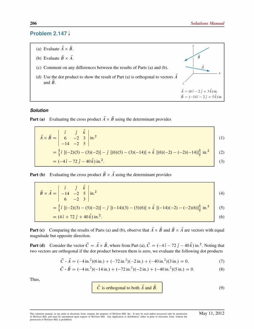
206 Solutions Manual
Problem 2.147
(a) Evaluate EA � EB .
(b) Evaluate EB � EA.
(c) Comment on any differences between the results of Parts (a) and (b).
(d) Use the dot product to show the result of Part (a) is orthogonal to vectors EAand EB .
Solution
Part (a) Evaluating the cross product EA � EB using the determinant provides
EA � EB D
ˇˇ O{ O| Ok
6 �2 3
�14 �2 5
ˇˇ in.2
D
nO{ Œ.�2/.5/ � .3/.�2/� � O| Œ.6/.5/ � .3/.�14/�C Ok Œ.6/.�2/ � .�2/.�14/�
oin.2
D .�4 O{ � 72 O| � 40 Ok/ in.2:
(1)
(2)
(3)
Part (b) Evaluating the cross product EB � EA using the determinant provides
EB � EA D
ˇˇ O{ O| Ok
�14 �2 5
6 �2 3
ˇˇ in.2
D
nO{ Œ.�2/.3/ � .5/.�2/� � O| Œ.�14/.3/ � .5/.6/�C Ok Œ.�14/.�2/ � .�2/.6/�
oin.2
D .4 O{ C 72 O| C 40 Ok/ in.2:
(4)
(5)
(6)
Part (c) Comparing the results of Parts (a) and (b), observe that EA � EB and EB � EA are vectors with equalmagnitude but opposite direction.
Part (d) Consider the vector EC D EA� EB , where from Part (a), EC D .�4 O{ � 72 O| � 40 Ok/ in.2. Noting thattwo vectors are orthogonal if the dot product between them is zero, we evaluate the following dot products
EC � EA D .�4 in:2/.6 in:/C .�72 in:2/.�2 in:/C .�40 in:2/.3 in:/ D 0; (7)
EC � EB D .�4 in:2/.�14 in:/C .�72 in:2/.�2 in:/C .�40 in:2/.5 in:/ D 0: (8)
Thus,
EC is orthogonal to both EA and EB . (9)
May 11, 2012This solutions manual, in any print or electronic form, remains the property of McGraw-Hill, Inc. It may be used and/or possessed only by permissionof McGraw-Hill, and must be surrendered upon request of McGraw-Hill. Any duplication or distribution, either in print or electronic form, without thepermission of McGraw-Hill, is prohibited.

Statics 2e 207
Problem 2.148
(a) Evaluate EA � EB .
(b) Evaluate EB � EA.
(c) Comment on any differences between the results of Parts (a) and (b).
(d) Use the dot product to show the result of Part (a) is orthogonal to vectors EAand EB .
Solution
Part (a) Evaluating the cross product EA � EB yields
EA � EB D
ˇˇ O{ O| Ok
�12 16 �15
18 6 �13
ˇˇ in.�lb (1)
D
nO{�.16/.�13/ � .�15/.6/
�� O|
�.�12/.�13/ � .�15/.18/
�C Ok
�.�12/.6/ � .16/.18/
� oin.�lb (2)
D .�118 O{ � 426 O| � 360 Ok/ in.�lb. (3)
Part (b) Evaluating the cross product EB � EA yields
EB � EAD
ˇˇ O{ O| Ok
18 6 �13
�12 16 �15
ˇˇ in.�lb (4)
D
nO{�.6/.�15/ � .�13/.16/
�� Oj
�.18/.�15/ � .�13/.�12/
�C Ok
�.18/.16/ � .6/.�12/
� oin.�lb (5)
D .118 O{ C 426 O| C 360 Ok / in.�lb. (6)
Part (c) Comparing the results of parts (a) and (b), observe that EA � EB and EB � EA are vectors with equalmagnitude but opposite direction.
Part (d) Consider the vector EC D EA � EB , where from Part (a), EC D .�118 O{ � 426 O| � 360 Ok/ in. �lb:Noting that two vectors are orthogonal if the dot product between them is zero, we evaluate the following dotproducts
EC � EAD .�118 in.�lb/.�12 lb/C .�426 in.�lb/.16 lb/C .�360 in.�lb/.�15 lb/ D 0; (7)EC � EB D .�118 in.�lb/.18 in/C .�426 in.�lb/.6 in/C .�360 in.�lb/.�13 in./ D 0: (8)
Thus,
The vector EC D EA � EB is orthogonal to both EA and EB:
May 11, 2012This solutions manual, in any print or electronic form, remains the property of McGraw-Hill, Inc. It may be used and/or possessed only by permissionof McGraw-Hill, and must be surrendered upon request of McGraw-Hill. Any duplication or distribution, either in print or electronic form, without thepermission of McGraw-Hill, is prohibited.

208 Solutions Manual
Problem 2.149
(a) Evaluate EA � EB .
(b) Evaluate EB � EA.
(c) Comment on any differences between the results of Parts (a) and (b).
(d) Use the dot product to show the result of Part (a) is orthogonal to vectors EAand EB .
Solution
Part (a) Evaluating the cross product EA � EB yields
EA � EB D
ˇˇ O{ O| Ok
4 3 12
�2 5 �14
ˇˇN�m (1)
D
nO{�.3/.�14/ � .12/.5/
�� O|
�.4/.�14/ � .12/.�2/
�C Ok
�.4/.5/ � .3/.�2/
�oN�m (2)
D .�102 O{ C 32 O| C 26 Ok/ N�m. (3)
Part (b) Evaluating the cross product EB � EA yields
EB � EAD
ˇˇ O{ O| Ok
�2 5 �14
4 3 12
ˇˇN�m (4)
D
nO{�.5/.12/ � .�14/.3/
�� O|
�.�2/.12/ � .�14/.4/
�C Ok
�.�2/.3/ � .5/.4/
�oN�m. (5)
D .102 O{ � 32 O| � 26 Ok/N�m. (6)
Part (c) Comparing the results of Parts (a) and (b), observe that EA � EB and EB � EA are vectors with equalmagnitude but opposite direction.
Part (d) Consider the vector EC D EA � EB , where from Part (a), EC D .�102 O{ C 32 O| C 26 Ok/N �m:Noting that two vectors are orthogonal if the dot product between them is zero, we evaluate the following dotproducts
EC � EAD .�102 N�m/.4 N/C .32 N�m/.3 N/C .26 N�m/.12 N/ D 0; (7)EC � EB D .�102 N�m/.�2 m/C .32 N�m/.5 N/C .26 N�m/.�14 m/ D 0: (8)
May 11, 2012This solutions manual, in any print or electronic form, remains the property of McGraw-Hill, Inc. It may be used and/or possessed only by permissionof McGraw-Hill, and must be surrendered upon request of McGraw-Hill. Any duplication or distribution, either in print or electronic form, without thepermission of McGraw-Hill, is prohibited.

Statics 2e 209
Thus,
The vector EC D EA � EB is orthogonal to both EA and EB:
May 11, 2012This solutions manual, in any print or electronic form, remains the property of McGraw-Hill, Inc. It may be used and/or possessed only by permissionof McGraw-Hill, and must be surrendered upon request of McGraw-Hill. Any duplication or distribution, either in print or electronic form, without thepermission of McGraw-Hill, is prohibited.

210 Solutions Manual
Problem 2.150
Describe how the cross product operation can be used to determine (or “test”) whether two vectors EA andEB are orthogonal. Is this test as easy to use as the test based on the dot product? Explain, perhaps using an
example to support your remarks. Note: Concept problems are about explanations, not computations.
Solution
Consider the following relation:EC D EA � EB D AB sin � Ou: (1)
If the vectors EA and EB are orthogonal, then � D 90ı and sin � D 1. Therefore, the following test oforthogonality, which consists of three steps, may be used:
1) Compute the vector EC using EC D EA � EB .
2) Evaluate the magnitudes A, B , and C .
3) If C D AB , then the vectors are orthogonal; if C ¤ AB , then the vectors are not orthogonal.
Using the dot product to test for orthogonality requires only two steps:1) Compute the dot product EA � EB .
2) If EA � EB D 0, then the vectors are orthogonal; if EA � EB ¤ 0, then the vectors are not orthogonal.Furthermore, the dot product is usually easier to evaluate than the cross product. Hence, the dot product testis easier to use compared to the cross product test described above.
May 11, 2012This solutions manual, in any print or electronic form, remains the property of McGraw-Hill, Inc. It may be used and/or possessed only by permissionof McGraw-Hill, and must be surrendered upon request of McGraw-Hill. Any duplication or distribution, either in print or electronic form, without thepermission of McGraw-Hill, is prohibited.

Statics 2e 211
Problem 2.151
Imagine a left-hand coordinate system has inadvertently been used for a problem. That is, if the x and ydirections have been selected first, the ´ direction has been taken in the wrong direction for a right-handcoordinate system. What consequences will this have for dot products and cross products? Perhaps use anexample to support your remarks.
Solution
If a left-hand coordinate system is used, the dot product may still be employed and all remarks made in thebook regarding its use and interpretation are still applicable. To see why, consider
EA � EB D AxBx C AyBy C A´B´: (1)
ı
ı×
x
y
z
If the ´ direction has been taken incorrectly for a right-hand system, the signs onboth A´ and B´ are changed—if both are changed, there will be no net changein the resulting dot product. For the cross product, vector directions given by thedeterminant will be wrong. To see why, consider the left-hand coordinate systemshown in the figure to the right. Using the basic definition of the cross productto evaluate O{ � O| , we write
O{ � O| D jO{j j O| j cos � Ou; (2)
where Ou is a unit vector given by the right-hand rule; according to this definition, O{ � O| is a vector that pointsupward (in the �´ direction) in the figure.
Evaluating O{ � O| using the determinant method provides
O{ � O| D
ˇˇ O{ O| Ok
1 0 0
0 1 0
ˇˇ D O{ .0/ � O| .0/C Ok Œ.1/.1/ � 0� D Ok: (3)
where Ok, by definition, is a unit vector in the positive ´ direction. Therefore, for Eq.(3) to give properdirections, and hence agree with Eq. (2), a right-hand coordinate system must be used.
May 11, 2012This solutions manual, in any print or electronic form, remains the property of McGraw-Hill, Inc. It may be used and/or possessed only by permissionof McGraw-Hill, and must be surrendered upon request of McGraw-Hill. Any duplication or distribution, either in print or electronic form, without thepermission of McGraw-Hill, is prohibited.

212 Solutions Manual
Problem 2.152
The corner of a tent is supported using three ropes having the forces shown. Wewish to compute the sum of the cross products EMO D ErOA �
EFAB C ErOA �
EFAC C ErOA �EFAD where ErOA is the position vector from points O to A, EFAB
is the force directed from points A to B , and so on.(a) Rather than compute three separate cross products to find EMO , do the
properties of the cross product permit EMO to be found using just onecross product? Explain.
(b) Determine EMO .
Solution
Part (a) As specified in the problem statement, the vector EMO is given by
EMO D ErOA �EFAB C ErOA �
EFAC C ErOA �EFAD: (1)
Rather than evaluate Eq. (1), the distributive property of the cross product may be used to rewrite Eq. (1) as
EMO D ErOA � . EFAB CEFAC C
EFAD/: (2)
Because Eq. (2) requires the evaluation of only one cross product, it will probably be more convenient to usethan Eq. (1) for determining EMO .
Part (b) To carry out the evaluation for EMO , either Eq. (1) or Eq. (2) may be used, and we will use Eq. (2).Expressions for the three force vectors are
EFAB D 150 lb
72 O{ � 96 Okp.72/2 C .�96/2
!D .90:00 O{ � 120:0 Ok/ lb; (3)
EFAC D 100 lb
72 O{ C 72 O| � 96 Okp
.72/2 C .72/2 C .�96/2
!D .51:45 O{ C 51:45 O| � 68:60 Ok/ lb; (4)
EFAD D 250 lb
72 O| � 96 Okp.72/2 C .�96/2
!D .150:0 O| � 200:0 Ok/ lb; (5)
such thatEFAB C
EFAC CEFAD D .141:4 O{ C 201:4 O| � 388:6 Ok/ lb: (6)
The position vector ErOA D 96 in: Ok. Therefore, using Eq. (2), we obtain
EMO D
ˇˇ O{ O| Ok
0 0 96
141:4 201:4 �388:6
ˇˇ in.�lb
D
nŒ0 � .96/.201:4/� O{ � Œ0 � .96/.141:4/� O| C Œ0 � 0� Ok
oin.�lb
D .�19300 O{ C 13600 O|/ in.�lb
(7)
(8)
(9)
May 11, 2012This solutions manual, in any print or electronic form, remains the property of McGraw-Hill, Inc. It may be used and/or possessed only by permissionof McGraw-Hill, and must be surrendered upon request of McGraw-Hill. Any duplication or distribution, either in print or electronic form, without thepermission of McGraw-Hill, is prohibited.

Statics 2e 213
Problem 2.153
For the triangular-shaped window of Prob. 2.109 on p. 95, use the cross product to determine the outwardnormal unit vector (i.e., pointing away from the origin) and the area of the window.
Solution
Our strategy will be to determine the outward normal vector En to the window by taking the cross productbetween two vectors that lie along the edges of the window. Among the several vectors that may be used, wewill employ the following
ErAB D
h.�25 � 35/ O{ C .30 � 25/ O| C .105 � 90/ Ok
icm D .�60 O{ C 5 O| C 15 Ok/ cm; (1)
ErAC D
h.15 � 35/ O{ C .60 � 25/ O| C .80 � 90/ Ok
icm D .�20 O{ C 35 O| � 10 Ok/ cm: (2)
To obtain an outward normal vector (as opposed to an inward normal vector), we examine the figure inProb. 2.109, and apply the right-hand rule, to determine that the vectors in the cross product must be taken inthe order ErAC first and ErAB second, as follows
En D ErAC � ErAB (3)
D
ˇˇ O{ O| Ok
�20 35 �10
�60 5 15
ˇˇ cm2 (4)
D
nŒ.35/.15/ � .�10/.5/� O{ � Œ.�20/.15/ � .�10/.�60/� O| C Œ.�20/.5/ � .35/.�60/� Ok
ocm2 (5)
D .575 O{ C 900 O| C 2000 Ok/ cm2; (6)
n D
q.575 cm/2 C .900 cm/2 C .2000 cm/2 D 2267 cm2: (7)
We may confirm that the result in Eq. (6) is indeed an outward normal vector by verifying that the componentsin Eq. (6) correspond to the outward direction from the window (i.e., away from the origin of the coordinatesystem). Using Eqs. (6) and (7), the outward normal unit vector is then given by
Ou DEn
nD.575 O{ C 900 O| C 2000 Ok/ cm2
2267 cm2 D 0:254 O{ C 0:397 O| C 0:882 Ok: (8)
The magnitude of the cross product ErAC � ErAB is the area of a parallelogram, which is twice the area ofthe triangular window ABC . Thus, using Eq. (7), we find that the area AABC of the window is
AABC D2267 cm2
2D 1130 cm2: (9)
May 11, 2012This solutions manual, in any print or electronic form, remains the property of McGraw-Hill, Inc. It may be used and/or possessed only by permissionof McGraw-Hill, and must be surrendered upon request of McGraw-Hill. Any duplication or distribution, either in print or electronic form, without thepermission of McGraw-Hill, is prohibited.

214 Solutions Manual
Problem 2.154
A flat quadrilateral plate finite element is shown (see Example 2.21 onp. 110 for a description of what a finite element is).
(a) Describe and perform a test, using two cross products that willverify if all four nodes (corners) lie in the same plane.
(b) Determine the unit outward normal direction to the surface (i.e.,pointing away from the origin).
(c) Determine the surface area of the element.
Solution
Part (a) We will begin by computing two vectors that are normal to the surface: En1 D Er12 � Er14 andEn2 D Er34� Er32. If En1=n1 equals En2=n2, that is, if the unit normal vectors are identical, then the plane formedby points 1, 2, and 4 and the plane formed by points 2, 3, and 4 are the same and hence all four corners of theplate finite element will lie in the same plane. The four position vectors to be used are
Er12 D
h.25 � 20/ O{ C .40 � 20/ O| C .7 � 12/ Ok
icm D .5 O{ C 20 O| � 5 Ok/ cm; (1)
Er14 D
h.5 � 20/ O{ C .20 � 20/ O| C .15 � 12/ Ok
icm D .�15 O{ C 0 O| C 3 Ok/ cm; (2)
Er32 D
h.25 � 0/ O{ C .40 � 35/ O| C .7 � 13/ Ok
icm D .25 O{ C 5 O| � 6 Ok/ cm; (3)
Er34 D
h.5 � 0/ O{ C .20 � 35/ O| C .15 � 13/ Ok
icm D .5 O{ � 15 O| C 2 Ok/ cm: (4)
The normal direction vectors discussed above are given by
En1 D
ˇˇ O{ O| Ok
5 20 �5
�15 0 3
ˇˇ cm2 (5)
D
nŒ.20/.3/ � .�5/.0/� O{ � Œ.5/.3/ � .�5/.�15/� O| C Œ.5/.0/ � .20/.�15/� Ok
ocm2 (6)
D .60 O{ C 60 O| C 300 Ok/ cm2; (7)
En2 D
ˇˇ O{ O| Ok
5 �15 2
25 5 �6
ˇˇ cm2 (8)
D
nŒ.�15/.�6/ � .2/.5/� O{ � Œ.5/.�6/ � .2/.25/� O| C Œ.5/.5/ � .�15/.25/� Ok
ocm2 (9)
D .80 O{ C 80 O| C 400 Ok/ cm2; (10)
where the magnitudes of the above vectors are
n1 D
q.60/2 C .60/2 C .300/2 cm2
D 311:8 cm2; n2 D
q.80/2 C .80/2 C .400/2 cm2
D 415:7 cm2:
(11)The unit vectors corresponding to En1 and En2 are
Ou1 DEn1
n1D.60 O{ C 60 O| C 300 Ok/ cm2
311:8 cm2 D 0:1925 O{ C 0:1925 O| C 0:9623 Ok; (12)
May 11, 2012This solutions manual, in any print or electronic form, remains the property of McGraw-Hill, Inc. It may be used and/or possessed only by permissionof McGraw-Hill, and must be surrendered upon request of McGraw-Hill. Any duplication or distribution, either in print or electronic form, without thepermission of McGraw-Hill, is prohibited.

Statics 2e 215
Ou2 DEn2
n2D.80 O{ C 80 O| C 400 Ok/ cm2
415:7 cm2 D 0:1925 O{ C 0:1925 O| C 0:9623 Ok: (13)
Comparing Eqs. (12) and (13), we see that Ou1 D Ou2, and therefore
all the nodes (1,2,3,4) lie in the same plane.
Part (b) The outward normal direction is Ou D Ou1 D Ou2, hence
Ou D 0:192 O{ C 0:192 O| C 0:962 Ok: (14)
Part (c) The magnitude of En1, which is given by n1 in Eq. (11), gives the area of the parallelogram withthree of the corners given by points 1, 2, and 4. Similarly, the magnitude of En2, which is given by n2 inEq. (11), gives the area of the parallelogram with three of the corners given by points 2, 3, and 4. The area ofthe triangle 1-2-4 is given by n1=2 and the area of the triangle 2-3-4 is given by n2=2. Hence, the surfacearea of the quadrilateral plate element is given by
A1234 Dn1
2Cn2
2D311:8 cm2
2C415:7 cm2
2D 364 cm2: (15)
May 11, 2012This solutions manual, in any print or electronic form, remains the property of McGraw-Hill, Inc. It may be used and/or possessed only by permissionof McGraw-Hill, and must be surrendered upon request of McGraw-Hill. Any duplication or distribution, either in print or electronic form, without thepermission of McGraw-Hill, is prohibited.

216 Solutions Manual
Problem 2.155
A contractor is required to prepare a soil surface so that it is planar and thenormal direction to the surface is within 0.5ı of vertical. If the elevations atpoints A and B , relative to the elevation at point C , are �3:3 ft and �4:2 ft,respectively, determine the angle between the soil surface’s normal directionand the vertical, and if the surface is sufficiently level.
Solution
Our strategy will be to use the cross product to determine the normal direction to surfaceABC , En D ErCA�ErCB .We will then take the dot product of En with Ok to determine the angle between En and Ok.
ErCA D .400 O{ � 3:3 Ok/ ft; (1)
ErCB D .500 O| � 4:2 Ok/ ft; (2)
EnD ErCA � ErCB D
ˇˇ O{ Oj Ok
400 0 �3:3
0 500 �4:2
ˇˇ ft2 (3)
D
nO{�.0/.�4:2/ � .�3:3/.500/
�� Oj
�.400/.�4:2/ � .�3:3/.0/
�C Ok
�.400/.500/ � .0/.0/
�oft2 (4)
D .1650 O{ C 1680 Oj C 200;000 Ok/ ft2; (5)
nDˇEnˇD
q.1650/2 C .1680/2 C .200;000/2 ft2 D 200;014 ft2: (6)
The angle � between En and the vertical direction (´ axis) can be obtained using the dot product of En with avector in the ´ direction, namely Ok: Thus,
� D cos�1 En � Ok
n.1/(7)
D cos�1 .1650 ft2/.0/C .1680 ft2/.0/C .200;000 ft2/.1/.200;014 ft2/.1/
(8)
D 0:6746ı. (9)
Thus,
The soil surface is not sufficiently level.
May 11, 2012This solutions manual, in any print or electronic form, remains the property of McGraw-Hill, Inc. It may be used and/or possessed only by permissionof McGraw-Hill, and must be surrendered upon request of McGraw-Hill. Any duplication or distribution, either in print or electronic form, without thepermission of McGraw-Hill, is prohibited.

Statics 2e 217
Problem 2.156
Repeat Prob. 2.155 if the elevations at points A and B , relative to the elevationat point C , are 2:6 ft and �3:1 ft, respectively.
Solution
Our strategy will be to use the cross product to determine the normal direction to surfaceABC , En D ErCA�ErCB .We will then take the dot product of En with Ok to determine the angle between En and Ok.
ErCA D .400 O{ C 2:6 Ok/ ft, (1)
ErCB D .500 j � 3:1 Ok/ ft; (2)
EnD ErCA � ErCB D
ˇˇ O{ O| Ok
400 0 2:6
0 500 �3:1
ˇˇ ft2 (3)
D
nO{�.0/.�3:1/ � .2:6/.500/
�� O|
�.400/.�3:1/ � .2:6/.0/
�C Ok
�.400/.500/ � .0/.0/
�oft2 (4)
D .�1300 O{ C 1240 O| C 200;000 Ok/ ft2; (5)
nDˇEnˇD
q.�1300/2 C .1240/2 C .200;000/2 ft2 D 200;008 ft.2 (6)
The angle � between En and the vertical direction (´ axis) can be obtained using the dot product of En with avector in the ´ direction, namely Ok. Thus,
� D cos�1 En � Ok
n.1/(7)
D cos�1 .�800 ft2/.0/C .1240 ft2/.0/C .200;000 ft2/.1/.200; 008 ft2/.1/
(8)
D 0:5147ı: (9)
Thus,
The soil surface is not sufficiently level.
May 11, 2012This solutions manual, in any print or electronic form, remains the property of McGraw-Hill, Inc. It may be used and/or possessed only by permissionof McGraw-Hill, and must be surrendered upon request of McGraw-Hill. Any duplication or distribution, either in print or electronic form, without thepermission of McGraw-Hill, is prohibited.

218 Solutions Manual
Problem 2.157
An ergonomically designed key for a computer keyboard has an approximatelyflat surface defined by points A, B , and C and is subjected to a 1N force in thedirection normal to the key’s surface.
(a) In Fig. P2.157(a), motion of the key is in the ´ direction. Determinethe components of the force in directions normal and tangent to thekey’s motion. Comment on why it might be important to know thesecomponents.
(b) In Fig. P2.157(b), the switch mechanism is repositioned so that themotion of the key is in the direction of the line connecting points D andE, where this line has x, y, and ´ direction cosines of 0.123, 0.123, and0.985, respectively. Determine the components of the force in directionsnormal and tangent to the key’s motion. Comment on why this designmight be more effective than that in Part (a).
Solution
Part (a) To determine the vector representation for the 1N force, we must determine the direction of thisforce, which is normal to the surface of the key. Thus, we begin by determining the normal direction to thekey, which is defined by the plane containing points A, B , and C ; to accomplish this the following vectorswill be used
ErBA D
h.15 � 0/ O{ C .0 � 0/ O| C .10 � 15/ Ok
imm D .15 O{ C 0 O| � 5 Ok/mm; (1)
ErBC D
h.0 � 0/ O{ C .15 � 0/ O| C .12 � 15/ Ok
imm D .0 O{ C 15 O| � 3 Ok/mm: (2)
A vector that is normal to the surface of the key is given by
En D ErBA � ErBC (3)
D
ˇˇ O{ O| Ok
15 0 �5
0 15 �3
ˇˇ mm2 (4)
D
nŒ.0/.�3/ � .�5/.15/� O{ � Œ.15/.�3/ � .�5/.0/� O| C Œ.15/.15/ � .0/.0/� Ok
omm2 (5)
D .75 O{ C 45 O| C 225 Ok/mm2; (6)
n D
q.75/2 C .�45/2 C .225/2 mm2
D 241:4mm2; (7)
where En points upward from the surface of the key (i.e., positive ´ component). The vector representation ofthe force is then
EF D .�1N/En
nD .�1N/
.75 O{ C 45 O| C 225 Ok/mm2
241:4mm2 D .�0:3107 O{ � 0:1864 O| � 0:9321 Ok/N: (8)
Due to the 1N force, the motion of the key is in the �´ direction. Therefore, the component of the force inthis direction (i.e., tangent to the direction of motion) is given by the negative of the ´ component of EF inEq. (8), (i.e., the dot product of EF with � Ok) which is
Fk D 0:932N: (9)
May 11, 2012This solutions manual, in any print or electronic form, remains the property of McGraw-Hill, Inc. It may be used and/or possessed only by permissionof McGraw-Hill, and must be surrendered upon request of McGraw-Hill. Any duplication or distribution, either in print or electronic form, without thepermission of McGraw-Hill, is prohibited.

Statics 2e 219
The component of force normal to this direction is obtained using the Pythagorean theorem
F? D
q.1N/2 � .�0:9321N/2 D 0:362N: (10)
Both Fk and F? are important to know for purposes of designing the key. In particular, Fk is the portion ofthe 1N force that causes motion of the key.
Part (b) The direction of the key’s motion is ErED , where ErED D �ErDE . Thus
ErED D �ErDE D �.0:123 O{ C 0:123 O| C 0:985 Ok/
D �0:123 O{ � 0:123 O| � 0:985 Ok: (11)
With EF given by Eq. (8), the component of the force tangent (parallel) to ErED is
Fk D EF �ErED
rEDD .�0:3107 O{�0:1864 O| �0:9321 Ok/N � .�0:123 O{�0:123 O| �0:985 Ok/ D 0:9792N: (12)
The component of force normal to this direction is obtained using the Pythagorean theorem
F? D
q.1N/2 � .0:9792N/2 D 0:2028N: (13)
Thus, the components are given by
Fk D �0:979N; F? D 0:203N: (14)
This design may be more effective than that given in Part (a) for two reasons. First, the tangential componentof the force in Part (b) is larger, meaning that a greater force is available to cause motion of the key. Second,the normal component of the force for Part (b) is approximately one-half of the normal component of theforce found in Part (a). Note that a large value of the normal component of the force is probably not desirablesince it does not help produce motion of the key and it may lead to wear of the key.
May 11, 2012This solutions manual, in any print or electronic form, remains the property of McGraw-Hill, Inc. It may be used and/or possessed only by permissionof McGraw-Hill, and must be surrendered upon request of McGraw-Hill. Any duplication or distribution, either in print or electronic form, without thepermission of McGraw-Hill, is prohibited.

220 Solutions Manual
Problem 2.158
Impact of debris, both natural and artificial, is a significant hazard for spacecraft.Space Shuttle windows are routinely replaced because of damage due to impactwith small objects, and recent flights have employed evasive maneuvers toavoid impact with larger objects, whose orbits NASA constantly monitors. Forthe triangular-shaped window and the relative velocity of approach Ev shown,determine the components and vector components of the velocity in directionsnormal and tangent to the window. Note that this information is needed beforean analysis of damage due to impact can be performed.
Solution
Our strategy will be to determine the outward� normal vector En to the window by taking the cross productbetween two vectors that lie along the edges of the window. Among the several vectors that may be used, wewill employ the following
ErAB D
h.0 � 70/ O{ C .40 � 10/ O| C .0 � 5/ Ok
icm D .�70 O{ C 30 O| � 5 Ok/ cm; (1)
ErAC D
h.0 � 70/ O{ C .0 � 10/ O| C .50 � 5/ Ok
icm D .�70 O{ � 10 O| C 45 Ok/ cm: (2)
To obtain an outward normal vector, we examine the figure in the problem statement, and apply the right-handrule, to determine that the vectors in the cross product must be taken in the order ErAB first and ErAC second, asfollows
En D ErAB � ErAC D
ˇˇ O{ O| Ok
�70 30 �5
�70 �10 45
ˇˇ cm2 (3)
D
nŒ.30/.45/ � .�5/.�10/� O{ � Œ.�70/.45/ � .�5/.�70/� O| C Œ.�70/.�10/ � .30/.�70/� Ok
ocm2
(4)
D .1300 O{ C 3500 O| C 2800 Ok/ cm2; (5)
n D
q.1300/2 C .3500/2 C .2800/2 cm2
D 4667 cm2: (6)
To determine the component of Ev normal to the surface, use the dot product with unit vector En=n, as follows
vn D Ev �En
nD .12 km=s/.�0:545 O{ � 0:818 O| � 0:182 Ok/ �
.1300 O{ C 3500 O| C 2800 Ok/ cm2
4667 cm2 (7)
D �10:49 km=s: (8)
Noting that the magnitude of Ev is 12 km=s, the component of Ev tangent to the surface is given by
vt D
qv2 � v2
n D
q.12 km=s/2 � .�10:49 km=s/2 D 5:821 km=s: (9)
�The inward normal vector could be used just as well. If this is the case, vn in Eq. (8) becomes 10:49 km=s, while the results inEqs. (9) and (11)–(13) remain the same.
May 11, 2012This solutions manual, in any print or electronic form, remains the property of McGraw-Hill, Inc. It may be used and/or possessed only by permissionof McGraw-Hill, and must be surrendered upon request of McGraw-Hill. Any duplication or distribution, either in print or electronic form, without thepermission of McGraw-Hill, is prohibited.

Statics 2e 221
The vector components of the velocity are then given by
Evn D vnEn
nD .�10:49 km=s/
.1300 O{ C 3500 O| C 2800 Ok/ cm2
4667 cm2 ;
D .�2:92 O{ � 7:87 O| � 6:30 Ok/ km/s;
Evt D Ev � Evn D .�3:62 O{ � 1:95 O| C 4:11 Ok/ km/s:
(10)
(11)
(12)
The magnitudes of the velocity components can be determined from Eqs. (11) and (12), or by taking theabsolute values of the components found in Eqs. (8) and (9). Hence,
jEvnj D 10:5 km=s; jEvt j D 5:82 km=s: (13)
May 11, 2012This solutions manual, in any print or electronic form, remains the property of McGraw-Hill, Inc. It may be used and/or possessed only by permissionof McGraw-Hill, and must be surrendered upon request of McGraw-Hill. Any duplication or distribution, either in print or electronic form, without thepermission of McGraw-Hill, is prohibited.

222 Solutions Manual
Problem 2.159
The velocity of air approaching the rudder of an aircraft has magnitude 900 ft/sin the y direction. The rudder rotates about line OA.
(a) The position vector from B to C has the x, y, and ´ direction cosinessin˛, .cos˛/.cos 20ı/, and .� cos˛/.sin 20ı/, respectively. If the rud-der is rotated so that ˛ D 10ı, determine the components, and vectorcomponents, of the air velocity in directions normal and tangent to thesurface of the rudder.
(b) Using the geometry shown in Fig. P2.159, verify the direction cosinesstated in Part (a).
Solution
Part (a) Begin by writing ErBC , for ˛ D 10ı, as
ErBC D sin˛ O{ C cos˛ cos 20ı O| � cos˛ sin 20ı Ok D 0:1736 O{ C 0:9254 O| � 0:3368 Ok; (1)
and ErBO asErBO D � sin 20ı O| � cos 20ı Ok D �0:3420 O| � 0:9397 Ok: (2)
A vector En that is normal to the rudder is given by
En D ErBO � ErBC (3)
D
ˇˇ O{ O| Ok
0 �0:3420 �0:9397
0:1736 0:9254 �0:3368
ˇˇ (4)
D Œ.�0:3420/.�0:3368/ � .�0:9397/.0:9254/� O{ � Œ.0/.�0:3368/ � .�0:9397/.0:1736/� O|
C Œ.0/.0:9254/ � .�0:3420/.0:1736/� Ok (5)
D 0:9848 O{ � 0:1632 O| C 0:05939 Ok (6)
The normal vector En given in Eq. (6) is a unit vector, and henceforth will be called On in this solution. Thiscan be seen by verifying that Eq. (6) has unit magnitude, or by noticing that since ErBO and ErBC are unitvectors and the angle between these vectors is 90ı, their cross product is a unit vector. Based on the problemdescription, the velocity of air approaching the rudder is
Ev D 900 ft=s O| : (7)
The components of Ev in the normal and tangential directions to the rudder are
vn D Ev � On D .900 ft=s/.�0:1632/ D �146:9 ft=s; (8)
vt D
qv2 � v2
t D
q.900 ft=s/2 � .�146:9 ft=s/2 D 887:9 ft=s: (9)
Thus, the vector representations of the normal and tangential components of the velocity are
Evn D vn On D .�146:9 ft=s/.0:9848 O{ � 0:1632 O| C 0:05939 Ok/
D .�145 O{ C 24:0 O| � 8:72 Ok/ ft/s;
Evt D Ev � Evn D .145 O{ C 876 O| C 8:72 Ok/ ft/s:
(10)
(11)
(12)
May 11, 2012This solutions manual, in any print or electronic form, remains the property of McGraw-Hill, Inc. It may be used and/or possessed only by permissionof McGraw-Hill, and must be surrendered upon request of McGraw-Hill. Any duplication or distribution, either in print or electronic form, without thepermission of McGraw-Hill, is prohibited.

Statics 2e 223
The magnitudes of the velocity components can be determined from Eqs. (11) and (12), or by taking theabsolute values of the components found in Eqs. (8) and (9). Hence,
jEvnj D 147 ft=s; jEvt j D 888 ft=s: (13)
Part (b) Consider the figure to the right, where a second coordinatesystem with axes a, t , and n has been included. (Note that the a andx axes coincide, and the t and n axes lie in the xy plane.) Begin bywriting the components of ErBC in terms of the new coordinate axes,which results in
.rBC /a D rBC sin˛; .rBC /t D rBC cos˛; and .rBC /n D 0: (14)
Next, we write the components of the same vector ErBC in terms of thex, y, and ´ axes, which results in
.rBC /x D .rBC /a D rBC sin˛; (15)
.rBC /y D .rBC /t cos 20ı D rBC cos˛ cos 20ı; (16)
.rBC /´ D �.rBC /t sin 20ı D �rBC cos˛ sin 20ı: (17)
Based on the definition of direction cosines, the direction cosines for ErBC are
cos �x D.rBC /xrBC
D sin˛;
cos �y D.rBC /y
rBCD cos˛ cos 20ı;
cos �´ D.rBC /´
rBCD � cos˛ sin 20ı:
(18)
(19)
(20)
May 11, 2012This solutions manual, in any print or electronic form, remains the property of McGraw-Hill, Inc. It may be used and/or possessed only by permissionof McGraw-Hill, and must be surrendered upon request of McGraw-Hill. Any duplication or distribution, either in print or electronic form, without thepermission of McGraw-Hill, is prohibited.

224 Solutions Manual
Problem 2.160
Beam AB has rectangular cross section where point A is at the origin of thecoordinate system and point B has the coordinates B .1:2;�0:3; 2:4/m. Thevector Er1 D .1 O{ C 12 O| C 1 Ok/m is perpendicular to the axis AB of the beam(ErAB ), and is parallel to the thin dimension of the cross section.
(a) Verify that Er1 is indeed perpendicular to ErAB .
(b) Determine the unit vector Or2 that is perpendicular to both Er1 and ErAB andhas the orientation shown in the figure.
(c) The force EP applied to point B of the beam has 1000N magnitude anddirection angles �x D 144ı, �y D 72ı, and �´ D 60ı. Determinethe components of the 1000N force, namely PAB , P1, and P2, in thedirections ErAB , Er1, and Or2, respectively, as shown in the figure. Note: Forfuture work in mechanics of materials, it will be necessary to know theseforces.
Solution
Part (a) We will use the dot product to verify that Er1 and ErAB are orthogonal, as follows.
ErAB D .1:2 O{ � 0:3 O| C 2:4 Ok / m; rAB D 2:7 m; (1)
Er1 � ErAB D .1 m/.1:2 m/C .12 m/.�0:3 m/C .1 m/.2:4 m/ D 0: (2)
Since Er1 � ErAB D 0; the vectors Er1 and ErAB are perpendicular.
Part (b) We will use the cross product to determine a vector Er2 that is orthogonal to both Er1 and ErAB (note:for Er2 to have the orientation shown in the problem statement, Er1 must be taken as the first vector in the crossproduct and ErAB is the second vector).
Er2 D Er1 � ErAB D
ˇˇ O{ Oj Ok
1 12 1
1:2 �0:3 2:4
ˇˇm2 (3)
D
nO{�.12/.2:4/ � .1/.�0:3/
�� O|
�.1/.2:4/ � .1/.1:2/
�(4)
C Ok�.1/.�0:3/ � .12/.1:2/
�om2
D .29:1 O{ � 1:2 O| � 14:7 Ok/ m2: (5)
The unit vector in the direction of Er2 is
Or2 DEr2
r2D.29:1 O{ � 1:2 O| � 14:7 Ok/ m2
32:62 m2(6)
D 0:8920 O{ � 0:03678 O| � 0:4506 Ok. (7)
May 11, 2012This solutions manual, in any print or electronic form, remains the property of McGraw-Hill, Inc. It may be used and/or possessed only by permissionof McGraw-Hill, and must be surrendered upon request of McGraw-Hill. Any duplication or distribution, either in print or electronic form, without thepermission of McGraw-Hill, is prohibited.

Statics 2e 225
Part (c) Using the information provided in the problem statement,
EP D 1000N .cos 144ı O{ C cos 72ı O| C cos 60ı Ok/ (8)
D .�809:0 O{ C 309:0 O| C 500 Ok/ N: (9)
The dot product is used to determine the components of EP in the ErAB ; Er1; and Or2 directions, as follows
PAB DEP �ErAB
rABD.�809:0 N/.1:2 m/C .309:0 N/.�0:3 m/C .500 N/.2:4 m/
2:7 m(10)
D 50.55 N, (11)
P1 D EP �Er1
r1D.�809:0 N/.1 m/C .309:0 N/.12 m/C .500 N/.1 m/
12:08 m(12)
D 281.3 N, (13)
P2 D EP � Or2 D .�809:0 N/.0:8920/C .309:0 N/.�0:03678/C .500N/.�0:4506/ (14)
D �958.3 N. (15)
As a partial check of solution accuracy, we use the results in Eqs. (11), (13), and (15) to verify thatqP 2
AB C P21 C P
22 D 1000 N:
May 11, 2012This solutions manual, in any print or electronic form, remains the property of McGraw-Hill, Inc. It may be used and/or possessed only by permissionof McGraw-Hill, and must be surrendered upon request of McGraw-Hill. Any duplication or distribution, either in print or electronic form, without thepermission of McGraw-Hill, is prohibited.

226 Solutions Manual
Problem 2.161
Repeat Prob. 2.160 if the coordinates of point B are B .130;�60; 180/ in.,Er1 D .6 O{C 31 O| C 6 Ok/ in., and the force EP has 500 lb magnitude and directionangles �x D 108
ı, �y D 60ı, and �´ D 36
ı.
Solution
Part (a) We will use the dot product to verify that Er1 and ErAB are orthogonal, as follows.
ErAB D .130 O{ � 60 O| C 180 Ok/ in., rAB D 230 in., (1)
Er1 � ErAB D .6 in./.130 in./C .31 in./.�60 in:/C .6 in:/.180 in./ D 0: (2)
Since Er1 � ErAB D 0; the vectors Er1 and ErAB are perpendicular.
Part (b) We will use the cross product to determine a vector Er2 that is orthogonal to both Er1 and ErAB (note:for Er2 to have the orientation shown in the problem statement, Er1 must be taken as the first vector in the crossproduct and ErAB is the second vector).
Er2 D Er1 � ErAB D
ˇˇ O{ O| Ok
6 31 6
130 �60 180
ˇˇ in.2 (3)
D
nO{�.31/.180/ � .6/.�60/
�� O|
�.6/.180/ � .6/.130/
�C Ok
�.6/.�60/ � .31/.130/
�oin.2 (4)
D .5940 O{ � 300 O| � 4390 Ok/ in.2 (5)
The unit vector in the direction of Er2 is
Or2 DEr2
r2D.5940 O{ � 300 O| � 4390 Ok/ in.2
7392 in.2(6)
D 0:8035 O{ � 0:04058 O| � 0:5939 Ok. (7)
May 11, 2012This solutions manual, in any print or electronic form, remains the property of McGraw-Hill, Inc. It may be used and/or possessed only by permissionof McGraw-Hill, and must be surrendered upon request of McGraw-Hill. Any duplication or distribution, either in print or electronic form, without thepermission of McGraw-Hill, is prohibited.

Statics 2e 227
Part (c) Using the information provided in the problem statement,
EP D 500 lb .cos 108ı O{ C cos 60ı O| C cos 36ı Ok/ (8)
D .�154:5 O{ C 250 O| C 404:5 Ok/ lb: (9)
The dot product is used to determine the components of EP in the ErAB ; Er1, and Or2 directions, as follows.
PAB DEP �ErAB
rABD.�154:5 lb/.130 in./C .250 lb/.�60 in./C .404:5 lb/.180 in:/
230 in:(10)
D 164:0 lb; (11)
P1 D EP �Er1
r1D.�154:5 lb/.6 in./C .250 lb/.31 in./C .404:5 lb/.6 in./
32:14 in.(12)
D 287:8 lb; (13)
P2 D EP � Or2 D .�154:5 lb/.0:8035/C .250 lb/.�0:04058/C .404:5 lb/.�0:5939/ (14)
D �374:5 lb: (15)
As a partial check of solution accuracy, we use the results in Eqs. (11), (13), and (15) to verify thatqP 2
AB C P21 C P
22 D 500 lb:
May 11, 2012This solutions manual, in any print or electronic form, remains the property of McGraw-Hill, Inc. It may be used and/or possessed only by permissionof McGraw-Hill, and must be surrendered upon request of McGraw-Hill. Any duplication or distribution, either in print or electronic form, without thepermission of McGraw-Hill, is prohibited.

228 Solutions Manual
Problem 2.162
StructureABCD is rigid and is built-in at pointA. PointA is at the origin of thecoordinate system, points B and D have the coordinates B .16; 24; 48/ in. andD .26; 52;�2/ in., and point C is at the midpoint of the straight bar AB . Por-tion CD of the structure is perpendicular to bar AB .
(a) Verify that portion CD of the structure is indeed perpendicular to barAB .
(b) Determine the unit vector Or that is perpendicular to both AB and CDsuch that this vector has a positive x component.
(c) The force EP applied to point D of the structure has 600 lb magnitudeand direction angles �x D 108ı, �y D 36ı, and �´ D 60ı. Determinethe components of the 600 lb force, namely PAB , PCD , and Pr , in thedirections AB , CD, and Or , respectively.
NOTE: The first printing of this book has an error in the last sentence of the statement for Part (c). Theforce referenced in the last sentence should be 600 lb (not 50N). This error is corrected in the second andsubsequent printings of the book.
Solution
Part (a) We will use the dot product to verify that the position vectors ErAB and ErCD are orthogonal, asfollows, where the coordinates of point C are C.8; 12; 24/ in.
ErAB D .16 O{ C 24 O| C 48 Ok/ in., rAB D 56 in., (1)
ErCD D�.26 � 8/ O{ C .52 � 12/ O| C .�2 � 24/ Ok
�in. (2)
D .18 O{ C 40 O| � 26 Ok/ in.; (3)
ErAB � ErCD D .16 in./.18 in./C .24 in./.40 in./C .48 in./.�26 in./ D 0: (4)
Since ErAB � ErCD D 0; the vectors ErAB and ErCD are perpendicular.
Part (b) We will use the cross product to determine a vector Er that is orthogonal to both ErAB and ErCD (note:for Er to have a positive x component, we will take ErCD to be the first vector in the cross product and ErAB isthe second vector).
Er D ErCD � ErAB D
ˇˇ O{ O| Ok
18 40 �26
16 24 48
ˇˇ in.2 (5)
D
nO{�.40/.48/ � .�26/.24/
�� O|
�.18/.48/ � .�26/.16/
�C Ok
�.18/.24/ � .40/.16/
�oin.2 (6)
D .2544 O{ � 1280 O| � 208 Ok/ in.2 (7)
The unit vector in the direction of Er is
Or DEr
rD.2544 O{ � 1280 O| � 208 Ok/ in.2
2855:5 in.2(8)
May 11, 2012This solutions manual, in any print or electronic form, remains the property of McGraw-Hill, Inc. It may be used and/or possessed only by permissionof McGraw-Hill, and must be surrendered upon request of McGraw-Hill. Any duplication or distribution, either in print or electronic form, without thepermission of McGraw-Hill, is prohibited.

Statics 2e 229
D 0:8909 O{ � 0:4483 O| � 0:07284 Ok. (9)
Part (c) Using the information provided in the problem statement,
EP D 600 lb .cos 108ı O{ C cos 36ı O| C cos 60ı Ok/ (10)
D .�185:4 O{ C 485:4 O| C 300 Ok/ lb: (11)
The dot product is used to determine the components of EP in the ErAB ; ErCD; and Or directions, as follows.
PAB DEP �ErAB
rABD.�185:4 lb/.16 in./C .485:4 lb/.24 in./C .300 lb/.48 in./
56 in:(12)
D 412:2 lb; (13)
PCD DEP �ErCD
rCDD.�185:4 lb/.18 in./C .485:4 lb/.40 in./C .300 lb/.�26 in./
50:99 in.(14)
D 162:4 lb; (15)
Pr D EP � Or D .�185:4 lb/.0:8909/C .485:4 lb/.�0:4483/C .300 lb/.�0:07284/ (16)
D �404:6 lb. (17)
As a partial check of solution accuracy, we use the results in Eqs. (13), (15), and (17) to verify thatqP 2
AB C P2CD C P
2r D 600 lb:
May 11, 2012This solutions manual, in any print or electronic form, remains the property of McGraw-Hill, Inc. It may be used and/or possessed only by permissionof McGraw-Hill, and must be surrendered upon request of McGraw-Hill. Any duplication or distribution, either in print or electronic form, without thepermission of McGraw-Hill, is prohibited.

230 Solutions Manual
Problem 2.163
Repeat Prob. 2.162 if the coordinates of points B and D are B .20; 60; 90/mmand D .40; 110;�15/mm, and the force EP has 50N magnitude and directionangles �x D 135
ı, �y D 60ı, and �´ D 60
ı.
Solution
Part (a) We will use the dot product to verify that the position vectors ErAB and ErCD are orthogonal, asfollows, where the coordinates of point C are C.10; 30; 45/ mm.
ErAB D .20 O{ C 60 O| C 90 Ok/ mm; rAB D 110 mm; (1)
ErCD D�.40 � 10/ O{ C .110 � 30/ O| C .�15 � 45/ Ok
�mm (2)
D .30 O{ C 80 O| � 60 Ok/ mm, (3)
ErAB � ErCD D .20 mm/.30 mm/C .60 mm/.80 mm/C .90 mm/.�60 mm/ D 0: (4)
Since ErAB � ErCD D 0; the vectors ErAB and ErCD are perpendicular.
Part (b) We will use the cross product to determine a vector Er that is orthogonal to both ErAB and ErCD (note:for Er to have a positive x component, we will take ErCD to be the first vector in the cross product and ErAB isthe second vector).
Er D ErCD � ErAB D
ˇˇ O{ O| Ok
30 80 �60
20 60 90
ˇˇmm2 (5)
D
nO{�.80/.90/ � .�60/.60/
�� O|
�.30/.90/ � .�60/.20/
�C Ok
�.30/.60/ � .80/.20/
�omm2 (6)
D .10;800 O{ � 3900 O| C 200 Ok/ mm2: (7)
The unit vector in the direction of Er is
Or DEr
rD.10;800 O{ � 3900 O| C 200 Ok/ mm2
11484 mm2(8)
D 0:9404 O{ � 0:3396 O| C 0:01742 Ok. (9)
May 11, 2012This solutions manual, in any print or electronic form, remains the property of McGraw-Hill, Inc. It may be used and/or possessed only by permissionof McGraw-Hill, and must be surrendered upon request of McGraw-Hill. Any duplication or distribution, either in print or electronic form, without thepermission of McGraw-Hill, is prohibited.

Statics 2e 231
Part (c) Using the information provided in the problem statement,
EP D 50 N .cos 135ı O{ C cos 60ı O| C cos 60ı Ok/ (10)
D .�35:36 O{ C 25 O| C 25 Ok/ N: (11)
The dot product is used to determine the components of EP in the ErAB ; ErCD , and Or directions, as follows.
PAB DEP �ErAB
rABD.�35:36 N/.20 mm/C .25 N/.60 mm/C .25 N/.90 mm/
110 mm(12)
D 27:66 N, (13)
PCD DEP �ErCD
rCDD.�35:36 N/.30 mm/C .25 N/.80 mm/C .25 N/.�60 mm/
104:4 mm(14)
D �5:370 N; (15)
Pr D EP � Or D .�35:36 N/.0:9404/C .25 N/.�0:3396/C .25 N/.0:01742/ (16)
D �41:30 N: (17)
As a partial check of solution accuracy, we use the results in Eqs. (13), (15), and (17) to verify thatqP 2
AB C P2CD C P
2r D 50 N:
May 11, 2012This solutions manual, in any print or electronic form, remains the property of McGraw-Hill, Inc. It may be used and/or possessed only by permissionof McGraw-Hill, and must be surrendered upon request of McGraw-Hill. Any duplication or distribution, either in print or electronic form, without thepermission of McGraw-Hill, is prohibited.
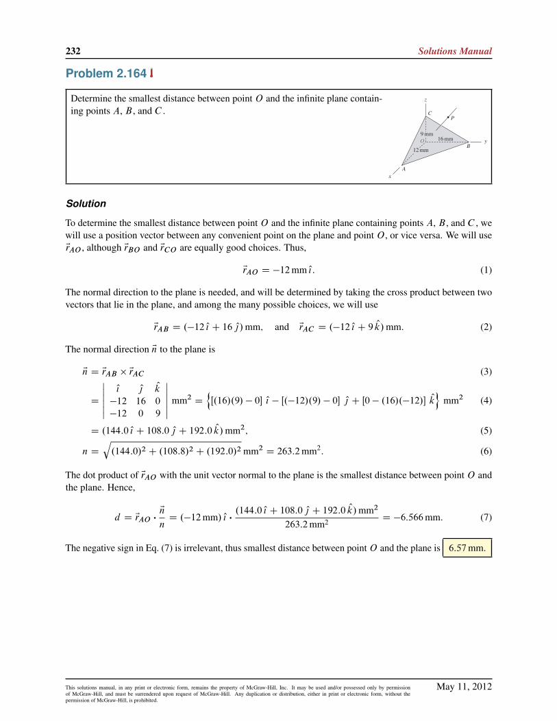
232 Solutions Manual
Problem 2.164
Determine the smallest distance between point O and the infinite plane contain-ing points A, B , and C .
Solution
To determine the smallest distance between point O and the infinite plane containing points A, B , and C , wewill use a position vector between any convenient point on the plane and point O , or vice versa. We will useErAO , although ErBO and ErCO are equally good choices. Thus,
ErAO D �12mm O{: (1)
The normal direction to the plane is needed, and will be determined by taking the cross product between twovectors that lie in the plane, and among the many possible choices, we will use
ErAB D .�12 O{ C 16 O|/mm; and ErAC D .�12 O{ C 9 Ok/mm: (2)
The normal direction En to the plane is
En D ErAB � ErAC (3)
D
ˇˇ O{ O| Ok
�12 16 0
�12 0 9
ˇˇ mm2
D
nŒ.16/.9/ � 0� O{ � Œ.�12/.9/ � 0� O| C Œ0 � .16/.�12/� Ok
omm2 (4)
D .144:0 O{ C 108:0 O| C 192:0 Ok/mm2; (5)
n D
q.144:0/2 C .108:8/2 C .192:0/2 mm2
D 263:2mm2: (6)
The dot product of ErAO with the unit vector normal to the plane is the smallest distance between point O andthe plane. Hence,
d D ErAO �En
nD .�12mm/ O{ �
.144:0 O{ C 108:0 O| C 192:0 Ok/mm2
263:2mm2 D �6:566mm: (7)
The negative sign in Eq. (7) is irrelevant, thus smallest distance between pointO and the plane is 6:57mm.
May 11, 2012This solutions manual, in any print or electronic form, remains the property of McGraw-Hill, Inc. It may be used and/or possessed only by permissionof McGraw-Hill, and must be surrendered upon request of McGraw-Hill. Any duplication or distribution, either in print or electronic form, without thepermission of McGraw-Hill, is prohibited.

Statics 2e 233
Problem 2.165
The vector from point O to point P has magnitude 40mm and has equaldirection angles with the x, y, and ´ axes. Determine the smallest distancefrom point P to the infinite plane containing points A, B , and C .
Solution
Direction angles must satisfy cos2 �x C cos2 �y C cos2 �´ D 1, and since �x D �y D �´, we may write
3 cos2 � D 1 ) cos � Dp1=3 D 0:5774 (1)
where � is the value each of the three direction angles. It follows that ErOP is given by
ErOP D .40mm/.0:5774 O{ C 0:5774 O| C 0:5774 Ok/ D .23:09 O{ C 23:09 O| C 23:09 Ok/mm: (2)
To determine the smallest distance between point P and the plane containing points A, B , and C , we willneed a position vector between some convenient point on the plane and point P . We will use ErAP (ErBP andErCP are also good choices), which can be written as
ErAP D ErAO C ErOP D .�12mm/ O{ C .23:09 O{ C 23:09 O| C 23:09 Ok/mm
D .11:09 O{ C 23:09 O| C 23:09 Ok/mm: (3)
The normal direction En to the plane may be determined by taking the cross product between two vectors thatlie in the plane. Among the many possible choices, we will use
ErAB D .�12 O{ C 16 O|/mm and ErAC D .�12 O{ C 9 Ok/mm; (4)
so that the normal direction is
En D ErAB � ErAC (5)
D
ˇˇ O{ O| Ok
�12 16 0
�12 0 9
ˇˇ mm2
D
nŒ.16/.9/ � 0� O{ � Œ.�12/.9/ � 0� O| C Œ0 � .16/.�12/� Ok
omm2 (6)
D .144:0 O{ C 108:0 O| C 192:0 Ok/mm2; (7)
n D
q.144:0/2 C .108:8/2 C .192:0/2 mm2
D 263:2mm2: (8)
The smallest distance between the plane and point P is given by the perpendicular line from the plane topoint P , and this may be determined using the following dot product
d D ErAP �En
n
D .11:09 O{ C 23:09 O| C 23:09 Ok/mm �.144:0 O{ C 108:0 O| C 192:0 Ok/mm2
263:2mm2
D 32:4mm. (9)
May 11, 2012This solutions manual, in any print or electronic form, remains the property of McGraw-Hill, Inc. It may be used and/or possessed only by permissionof McGraw-Hill, and must be surrendered upon request of McGraw-Hill. Any duplication or distribution, either in print or electronic form, without thepermission of McGraw-Hill, is prohibited.
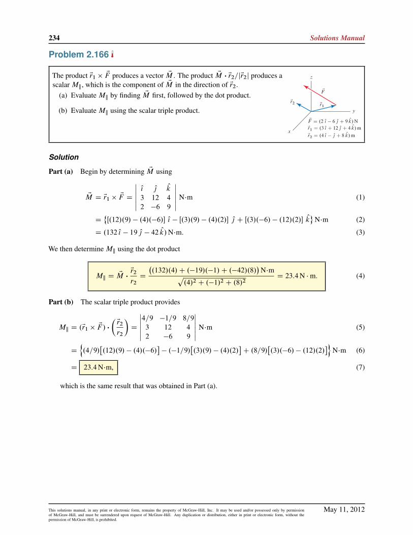
234 Solutions Manual
Problem 2.166
The product Er1 � EF produces a vector EM . The product EM � Er2=jEr2j produces ascalar Mk, which is the component of EM in the direction of Er2.
(a) Evaluate Mk by finding EM first, followed by the dot product.
(b) Evaluate Mk using the scalar triple product.
Solution
Part (a) Begin by determining EM using
EM D Er1 � EF D
ˇˇ O{ O| Ok
3 12 4
2 �6 9
ˇˇ N�m (1)
D˚Œ.12/.9/ � .4/.�6/� O{ � Œ.3/.9/ � .4/.2/� O| C Œ.3/.�6/ � .12/.2/� Ok
N�m (2)
D .132 O{ � 19 O| � 42 Ok/N�m: (3)
We then determine Mk using the dot product
Mk D EM �Er2
r2D
�.132/.4/C .�19/.�1/C .�42/.8/
�N�mp
.4/2 C .�1/2 C .8/2D 23:4N �m: (4)
Part (b) The scalar triple product provides
Mk D .Er1 � EF / �
�Er2
r2
�D
ˇˇ4=9 �1=9 8=9
3 12 4
2 �6 9
ˇˇ N�m (5)
D
n.4=9/
�.12/.9/ � .4/.�6/
�� .�1=9/
�.3/.9/ � .4/.2/
�C .8=9/
�.3/.�6/ � .12/.2/
�oN�m (6)
D 23:4N�m, (7)
which is the same result that was obtained in Part (a).
May 11, 2012This solutions manual, in any print or electronic form, remains the property of McGraw-Hill, Inc. It may be used and/or possessed only by permissionof McGraw-Hill, and must be surrendered upon request of McGraw-Hill. Any duplication or distribution, either in print or electronic form, without thepermission of McGraw-Hill, is prohibited.

Statics 2e 235
Problem 2.167
As described in connection with Fig. 2.34 on p. 105, the scalar triple product . EA � EB/ � EC provides thevolume of the parallelepiped formed by EA, EB , and EC . Comment on how the results of the following tripleproducts compare to the value provided by . EA � EB/ � EC :
(a) . EA � EC/ � EB .
(b) . EB � EC/ � EA.
(c) . EC � EB/ � EA.
(d) . EC � EA/ � EB .Note: Concept problems are about explanations, not computations.
Solution
The volume V of the parallelepiped is given by
V D . EA � EB/ � EC : (1)
Part (a)
. EA � EC/ � EB D �V: (2)
Part (b)
. EB � EC/ � EA D V: (3)
Part (c)
. EC � EB/ � EA D �V: (4)
Part (d)
. EC � EA/ � EB D V: (5)
May 11, 2012This solutions manual, in any print or electronic form, remains the property of McGraw-Hill, Inc. It may be used and/or possessed only by permissionof McGraw-Hill, and must be surrendered upon request of McGraw-Hill. Any duplication or distribution, either in print or electronic form, without thepermission of McGraw-Hill, is prohibited.

236 Solutions Manual
Problem 2.168
The manufacturer of a welded steel bracket specifies the work-ing loads depicted in the figure of Rn versus Rt . Values ofRn and Rt that lie within the shaded region are allowable,while values that lie outside of the region are unsafe. Sucha diagram is often called an interaction diagram because itcharacterizes the combined effect that multiple loads have onthe strength of a component. For the loading and geometryshown, determine the range of values load P may have andstill satisfy the manufacturer’s combined loading criterion.
Solution
Begin by writing the resultant force ER for any value of P
ER D EF C EP
D 2 kN.4=5/ O{ � 2 kN.3=5/ O| C P O|
D 1:6 kN O{ C .P � 1:2 kN/ O| : (1)
In the figure at the right, the sum EF C EP is shown. The force EF hasknown magnitude and direction, and it is sketched first. Then, twopossible vectors for force EP are shown; one possibility correspondsto P > 0 and the other to P < 0. Using some geometry, the valuesof P that cause the resultant force to tocuh the surface of allowableworking loads is determined, with the result
�.10 � 1:2/ kN � P � .5 � 1:6C 1:2/ kN; (2)
or�8:8 kN � P � 4:6 kN: (3)
May 11, 2012This solutions manual, in any print or electronic form, remains the property of McGraw-Hill, Inc. It may be used and/or possessed only by permissionof McGraw-Hill, and must be surrendered upon request of McGraw-Hill. Any duplication or distribution, either in print or electronic form, without thepermission of McGraw-Hill, is prohibited.
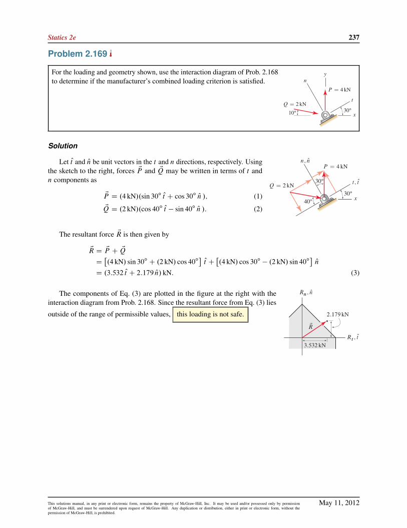
Statics 2e 237
Problem 2.169
For the loading and geometry shown, use the interaction diagram of Prob. 2.168to determine if the manufacturer’s combined loading criterion is satisfied.
Solution
Let Ot and On be unit vectors in the t and n directions, respectively. Usingthe sketch to the right, forces EP and EQ may be written in terms of t andn components as
EP D .4 kN/.sin 30ı Ot C cos 30ı On /; (1)
EQ D .2 kN/.cos 40ı Ot � sin 40ı On /: (2)
The resultant force ER is then given by
ER D EP C EQ
D�.4 kN/ sin 30ı C .2 kN/ cos 40ı
�Ot C
�.4 kN/ cos 30ı � .2 kN/ sin 40ı
�On
D .3:532 Ot C 2:179 On/ kN: (3)
The components of Eq. (3) are plotted in the figure at the right with theinteraction diagram from Prob. 2.168. Since the resultant force from Eq. (3) lies
outside of the range of permissible values, this loading is not safe.
May 11, 2012This solutions manual, in any print or electronic form, remains the property of McGraw-Hill, Inc. It may be used and/or possessed only by permissionof McGraw-Hill, and must be surrendered upon request of McGraw-Hill. Any duplication or distribution, either in print or electronic form, without thepermission of McGraw-Hill, is prohibited.

238 Solutions Manual
Problem 2.170
(a) Determine the resultant ER of the three forces EF C EP C EQ.
(b) If an additional force ET in the ˙x direction is to be added, determinethe magnitude it should have so that the magnitude of the resultant is assmall as possible.
Solution
Part (a) For force EF , by examining the figure in the problem statement, �x D 60ı. The 36ı angle is not a
direction angle, but �´ can be easily determined using
�´ D 180ı� 36ı D 144ı: (1)
The remaining direction angle �y may be determined by using cos2 �x C cos2 �y C cos2 �´ D 1, which canbe rearranged for
cos �y D ˙
p1 � cos2 �x � cos2 �´ D ˙0:3090 ) cos �y D 0:3090: (2)
In Eq. (2), we have selected the postive solution since force EF clearly has a positive y component. Thus, thevector expression for EF is
EF D .1 kN/.cos �x O{ C cos �y O| C cos �´Ok/
D .1 kN/.0:5000 O{ C 0:3090 O| � 0:8090 Ok/
D .0:5000 O{ C 0:3090 O| � 0:8090 Ok/ kN: (3)
For the force EP , we begin by determining the components in the´ and a directions, where the a direction is defined in the sketch at theright. Thus
P´ D .2 kN/ sin 40ı and Pa D .2 kN/ cos 40ı: (4)
The x and y components are then found from Pa as follows
Px D �Pa sin 30ı D �.2 kN/ cos 40ı sin 30ı; (5)
Py D Pa cos 30ı D .2 kN/ cos 40ı cos 30ı: (6)
Thus, the vector expression for EP is
EP D �.2 kN/ cos 40ı sin 30ı O{ C .2 kN/ cos 40ı cos 30ı O| C .2 kN/ sin 40ı Ok
D .�0:7660 O{ C 1:327 O| C 1:286 Ok/ kN: (7)
A partial check of accuracy, you should verify that the magnitude of Eq. (7) is 2 kN.For the force EQ, we begin by determining the components in the ´ and b directions, where the b direction
is defined in the sketch shown earlier. Thus
Q´ D �.3 kN/ cos 50ı and Qb D .3 kN/ sin 50ı: (8)
May 11, 2012This solutions manual, in any print or electronic form, remains the property of McGraw-Hill, Inc. It may be used and/or possessed only by permissionof McGraw-Hill, and must be surrendered upon request of McGraw-Hill. Any duplication or distribution, either in print or electronic form, without thepermission of McGraw-Hill, is prohibited.

Statics 2e 239
Noting thatp152 C 82 D 17, the x and y components are then found from Qb as follows
Qx D �Qb.15=17/ D �.3 kN/ sin 50ı.15=17/; (9)
Qy D Qb.8=17/ D .3 kN/ sin 50ı.8=17/: (10)
Thus, the vector expression for EQ is
EQ D �.3 kN/ sin 50ı.15=17/ O{ C .3 kN/ sin 50ı.8=17/ O| � .3 kN/ cos 50ı Ok
D .�2:028 O{ C 1:081 O| � 1:928 Ok/ kN: (11)
As a partial check of accuracy, you should verify that the magnitude of Eq. (11) is 3 kN.The resultant force is found by adding Eqs. (3), (7), and (11) to obtain
ER D EF C EP C EQ D .�2:29 O{ C 2:72 O| � 1:45 Ok/ kN: (12)
Part (b) To determine the force ET that will make the resultant force ER as small as possible, where ET isrequired to be in the˙x direction, we choose a force that will render the x component of ER equal to zero,hence
ET D .2:29 O{/ kN: (13)
May 11, 2012This solutions manual, in any print or electronic form, remains the property of McGraw-Hill, Inc. It may be used and/or possessed only by permissionof McGraw-Hill, and must be surrendered upon request of McGraw-Hill. Any duplication or distribution, either in print or electronic form, without thepermission of McGraw-Hill, is prohibited.

240 Solutions Manual
Problem 2.171
(a) Determine the resultant ER of the three forces EF C EP C EQ.
(b) If an additional force ET in the ˙x direction is to be added, determinethe magnitude it should have so that the magnitude of the resultant is assmall as possible.
Solution
Part (a) For force EF , by examining the figure in the problem statement, �y D 72ı. The 36ı angle is not a
direction angle, but �´ can be easily determined using
�´ D 180ı� 36ı D 144ı: (1)
The remaining direction angle �x may be determined by using
cos2 �x C cos2 �y C cos2 �´ D 1; (2)
which can be rearranged for
cos �x D ˙
q1 � cos2 �y � cos2 �´ D ˙0:5000 ) cos �x D 0:5000: (3)
In Eq. (3), we have selected the postive solution since force EF clearly has a positive x component. Thus, thevector expression for EF is
EF D .3 lb/.cos �x O{ C cos �y O| C cos �´Ok/
D .3 lb/.0:5000 O{ C 0:3090 O| � 0:8090 Ok/
D .1:5 O{ C 0:9271 O| � 2:427 Ok/ lb: (4)
For the force EP , we observe from the figure in the problem statement that the value of ˛ must satisfy anexpression similar to Eq. (2), which leads to �
3 cos2 ˛ D 1: (5)
Solving Eq. (5) providescos˛ D ˙0:5774 ) ˛ D 54:74ı; 125:3ı: (6)
By examining the figure in the problem statement, ˛ is clearly an accute angle, so we select ˛ D 54:74ı inEq. (6). By noting that the x, y, and ´ components of EP are negative, positive, and positive, respectively, thevector expression for EP is
EP D .1 lb/.�0:5774 O{ C 0:5774 O| C 0:5774 Ok/
D .�0:5774 O{ C 0:5774 O| C 0:5774 Ok/ lb: (7)
�By carefully examining the figure in the problem statement, the direction angles for EP are �x D 180ı � ˛, �y D ˛, and�´ D ˛. Substituting these direction angles in Eq.(2) and solving provides the solutions ˛ D 54:74ı; 125:3ı; the first of these, whichcorresponds to an acute angle, is the physically correct solution for this problem.
May 11, 2012This solutions manual, in any print or electronic form, remains the property of McGraw-Hill, Inc. It may be used and/or possessed only by permissionof McGraw-Hill, and must be surrendered upon request of McGraw-Hill. Any duplication or distribution, either in print or electronic form, without thepermission of McGraw-Hill, is prohibited.

Statics 2e 241
For the force EQ, we begin by determining the components in the yand a directions, where the a direction is defined in the sketch at the right.Thus
Qy D .2 lb/ sin 40ı; Qa D .2 lb/ cos 40ı: (8)
The x and ´ components are then found from Qa as follows
Qx D Qa cos 30ı D .2 lb/ cos 40ı cos 30ı; (9)
Q´ D Qa sin 30ı D .2 lb/ cos 40ı sin 30ı: (10)
Thus, the vector expression for EQ is
EQ D .2 lb/ cos 40ı cos 30ı O{ C .2 lb/ sin 40ı O| C .2 lb/ cos 40ı sin 30ı Ok (11)
D .1:327 O{ C 1:286 O| C 0:7660 Ok/ lb: (12)
As a partial check of accuracy, you should verify that the magnitude of Eq. (12) is 2 lb.The resultant force is found by adding Eqs. (4), (7), and (12) to obtain
ER D EF C EP C EQ D .2:25 O{ C 2:79 O| � 1:08 Ok/ lb: (13)
Part (b) To determine the force ET that will make the resultant force ER as small as possible, where ET isrequired to be in the˙x direction, we choose a force that will render the x component of ER equal to zero,hence
ET D �2:25 O{ lb: (14)
May 11, 2012This solutions manual, in any print or electronic form, remains the property of McGraw-Hill, Inc. It may be used and/or possessed only by permissionof McGraw-Hill, and must be surrendered upon request of McGraw-Hill. Any duplication or distribution, either in print or electronic form, without thepermission of McGraw-Hill, is prohibited.
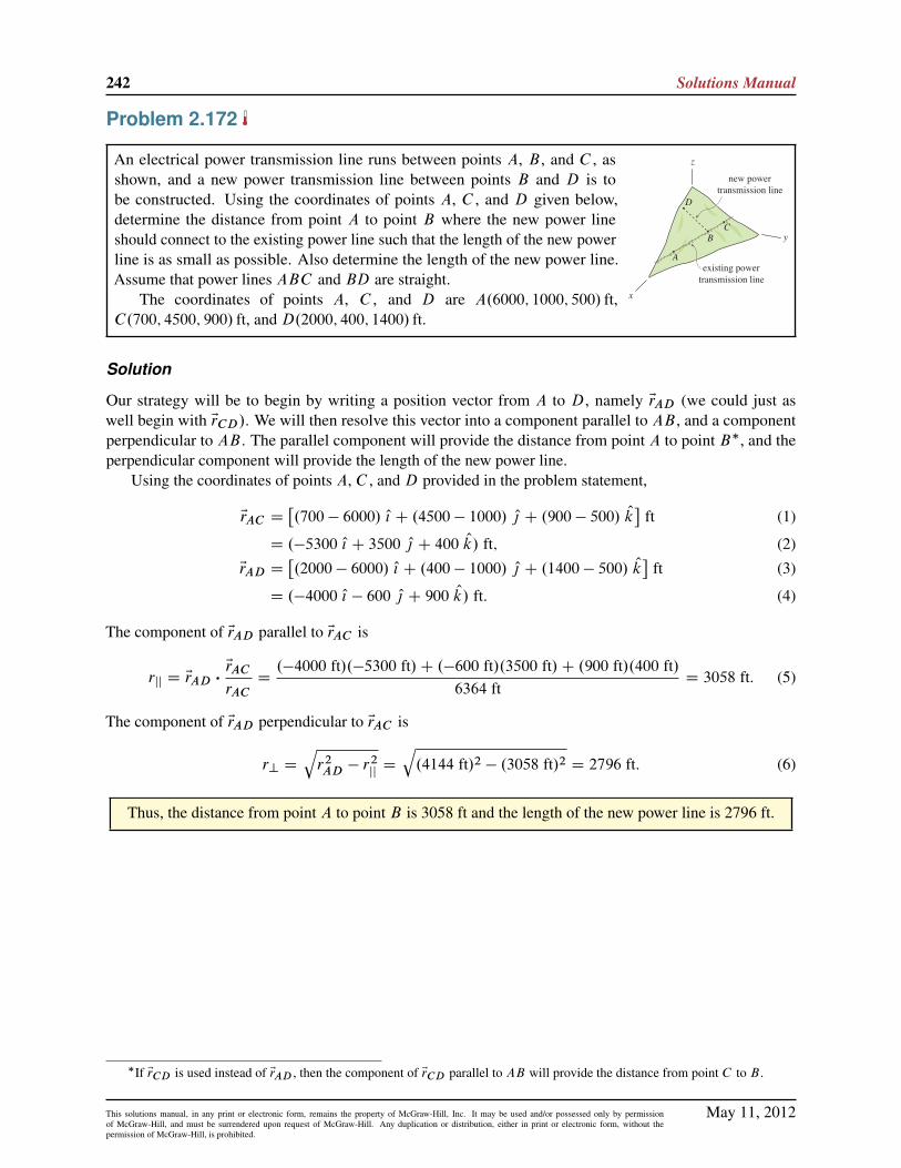
242 Solutions Manual
Problem 2.172
An electrical power transmission line runs between points A, B , and C , asshown, and a new power transmission line between points B and D is tobe constructed. Using the coordinates of points A, C , and D given below,determine the distance from point A to point B where the new power lineshould connect to the existing power line such that the length of the new powerline is as small as possible. Also determine the length of the new power line.Assume that power lines ABC and BD are straight.
The coordinates of points A, C , and D are A.6000; 1000; 500/ ft,C.700; 4500; 900/ ft, and D.2000; 400; 1400/ ft.
Solution
Our strategy will be to begin by writing a position vector from A to D, namely ErAD (we could just aswell begin with ErCD/. We will then resolve this vector into a component parallel to AB , and a componentperpendicular to AB . The parallel component will provide the distance from point A to point B�, and theperpendicular component will provide the length of the new power line.
Using the coordinates of points A, C , and D provided in the problem statement,
ErAC D�.700 � 6000/ O{ C .4500 � 1000/ O| C .900 � 500/ Ok
�ft (1)
D .�5300 O{ C 3500 O| C 400 Ok/ ft; (2)
ErAD D�.2000 � 6000/ O{ C .400 � 1000/ O| C .1400 � 500/ Ok
�ft (3)
D .�4000 O{ � 600 O| C 900 Ok/ ft: (4)
The component of ErAD parallel to ErAC is
rjj D ErAD �ErAC
rACD.�4000 ft/.�5300 ft/C .�600 ft/.3500 ft/C .900 ft/.400 ft/
6364 ftD 3058 ft. (5)
The component of ErAD perpendicular to ErAC is
r? Dqr2AD � r
2jjD
q.4144 ft/2 � .3058 ft/2 D 2796 ft: (6)
Thus, the distance from point A to point B is 3058 ft and the length of the new power line is 2796 ft.
�If ErCD is used instead of ErAD , then the component of ErCD parallel to AB will provide the distance from point C to B .
May 11, 2012This solutions manual, in any print or electronic form, remains the property of McGraw-Hill, Inc. It may be used and/or possessed only by permissionof McGraw-Hill, and must be surrendered upon request of McGraw-Hill. Any duplication or distribution, either in print or electronic form, without thepermission of McGraw-Hill, is prohibited.

Statics 2e 243
Problem 2.173
An electrical power transmission line runs between points A, B , and C , asshown, and a new power transmission line between points B and D is tobe constructed. Using the coordinates of points A, C , and D given below,determine the distance from point A to point B where the new power lineshould connect to the existing power line such that the length of the new powerline is as small as possible. Also determine the length of the new power line.Assume that power lines ABC and BD are straight.
The coordinates of points A, C , and D are A.3000; 600; 300/m,C.600; 2200; 500/m, and D.1000; 300; 800/m.
Solution
Our strategy will be to begin by writing a position vector from A to D, namely ErAD (we could just aswell begin with ErCD/. We will then resolve this vector into a component parallel to AB , and a componentperpendicular to AB . The parallel component will provide the distance from point A to point B�, and theperpendicular component will provide the length of the new power line.
Using the coordinates of points A, C , and D provided in the problem statement,
ErAC D�.600 � 3000/ O{ C .2200 � 600/ O| C .500 � 300/ Ok
�m (1)
D .�2400 O{ C 1600 O| C 200 Ok/ m; (2)
ErAD D�.1000 � 3000/ O{ C .300 � 600/ O| C .800 � 300/ Ok
�m (3)
D .�2000 O{ � 300 O| C 500 Ok/ m. (4)
The component of ErAD parallel to ErAC is
rjj D ErAD �ErAC
rACD.�2000 m/.�2400 m/C .�300 m/.1600 m/C .500 m/.200 m/
2891 mD 1529 m. (5)
The component of ErAD perpendicular to ErAC is
r? Dqr2AD � r
2jjD
q.2083 m/2 � .1529 m/2 D 1415 m: (6)
Thus, the distance from point A to point B is 1529 m and the length of the new power line is 1415 m.
�If ErCD is used instead of ErAD , then the component of ErCD parallel to AB will provide the distance from point C to B .
May 11, 2012This solutions manual, in any print or electronic form, remains the property of McGraw-Hill, Inc. It may be used and/or possessed only by permissionof McGraw-Hill, and must be surrendered upon request of McGraw-Hill. Any duplication or distribution, either in print or electronic form, without thepermission of McGraw-Hill, is prohibited.

244 Solutions Manual
Problem 2.174
An architect specifies the roof geometry shown for a building. Each of linesEAB , BD, DCG, EG, and AC are straight. Two forces of magnitude P andQ acting in the �y direction are applied at the positions shown.
Determine the components of the force P in directions normal and parallelto the roof at point A. Express your answer in terms of P .
Solution
The following vectors are obtained from the figure in the problem statement:
EP D �P O|; ErAB D .20 O{/m; and ErAC D .10 O| � 40 Ok/m: (1)
The vector perpendicular to ErAB and ErAC is given by
En D ErAB � ErAC D
ˇˇ O{ O| Ok
20 0 0
0 10 �40
ˇˇ m2 (2)
D˚.0 � 0/ O{ � Œ.20/.�40/ � .0/.0/� O| C Œ.20/.10/ � .0/.0/� Ok
m2 (3)
D .800 O| C 200 Ok/m2; (4)
n D
q.800m2/2 C .200m2/2 D 824:6m2: (5)
The component of EP that is perpendicular to the roof is given by
P? D EP �En
nD0C .�P /.800m2/C 0
824:6m2 D .�0:970/ P: (6)
The component of EP that is parallel to the roof is given by
Pk D
qP 2 � P 2
?D
qP 2 � .�0:970P /2 D .0:243/ P: (7)
May 11, 2012This solutions manual, in any print or electronic form, remains the property of McGraw-Hill, Inc. It may be used and/or possessed only by permissionof McGraw-Hill, and must be surrendered upon request of McGraw-Hill. Any duplication or distribution, either in print or electronic form, without thepermission of McGraw-Hill, is prohibited.
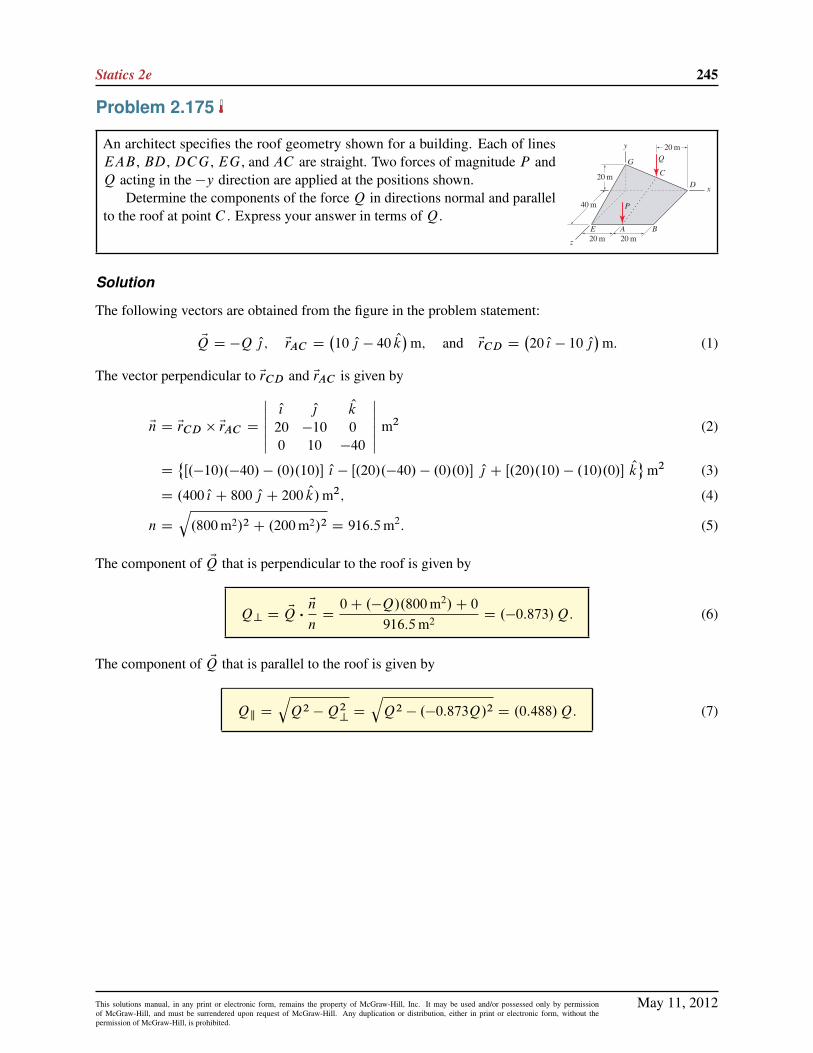
Statics 2e 245
Problem 2.175
An architect specifies the roof geometry shown for a building. Each of linesEAB , BD, DCG, EG, and AC are straight. Two forces of magnitude P andQ acting in the �y direction are applied at the positions shown.
Determine the components of the force Q in directions normal and parallelto the roof at point C . Express your answer in terms of Q.
Solution
The following vectors are obtained from the figure in the problem statement:
EQ D �Q O|; ErAC D�10 O| � 40 Ok
�m; and ErCD D
�20 O{ � 10 O|
�m: (1)
The vector perpendicular to ErCD and ErAC is given by
En D ErCD � ErAC D
ˇˇ O{ O| Ok
20 �10 0
0 10 �40
ˇˇ m2 (2)
D˚Œ.�10/.�40/ � .0/.10/� O{ � Œ.20/.�40/ � .0/.0/� O| C Œ.20/.10/ � .10/.0/� Ok
m2 (3)
D .400 O{ C 800 O| C 200 Ok/m2; (4)
n D
q.800m2/2 C .200m2/2 D 916:5m2: (5)
The component of EQ that is perpendicular to the roof is given by
Q? D EQ �En
nD0C .�Q/.800m2/C 0
916:5m2 D .�0:873/Q: (6)
The component of EQ that is parallel to the roof is given by
Qk D
qQ2 �Q2
?D
qQ2 � .�0:873Q/2 D .0:488/Q: (7)
May 11, 2012This solutions manual, in any print or electronic form, remains the property of McGraw-Hill, Inc. It may be used and/or possessed only by permissionof McGraw-Hill, and must be surrendered upon request of McGraw-Hill. Any duplication or distribution, either in print or electronic form, without thepermission of McGraw-Hill, is prohibited.

246 Solutions Manual
Problem 2.176
A concrete surface for a parking lot is to be prepared such that it is planar and thenormal direction to the surface is 2ı˙0:5ı of vertical so that rainwater will haveadequate drainage. If the coordinates of pointsA, B , and C areA .300; 50; 2/ ft,B .20; 150;�5/ ft, and C .280; 450;�8/ ft, determine the angle between theconcrete surface’s normal direction and the vertical, and if the concrete surfacemeets the drainage specification cited above.
Solution
Our strategy will be to use the cross product to determine the normal direction to surfaceABC , En D ErAC�ErAB .We will then take the dot product of En with Ok to determine the angle between En and Ok.
ErAC D�.280 � 300/ O{ C .450 � 50/ O| C .�8 � 2/ Ok
�ft (1)
D .�20 O{ C 400 O| � 10 Ok/ ft, (2)
ErAB D�.20 � 300/ O{ C .150 � 50/ O| C .�5 � 2/ Ok
�ft (3)
D .�280 O{ C 100 O| � 7 Ok/ ft, (4)
EnD ErAC � ErAB D
ˇˇ O{ O| Ok
�20 400 �10
�280 100 �7
ˇˇ ft2 (5)
D
nO{�.400/.�7/ � .�10/.100/
�� O|
�.�20/.�7/ � .�10/.�280/
�C Ok
�.�20/.100/ � .400/.�280/
�oft2 (6)
D .�1800 O{ C 2660 O| C 110;000 Ok/ ft2; (7)
nDˇEnˇD
q.1800/2 C .2660/2 C .110;000/2 ft2 D 110;047 ft2: (8)
The angle � between En and the vertical direction (´ axis) can be obtained using the dot product of En with avector in the ´ direction, namely Ok. Thus,
� D cos�1 En � Ok
n .1/(9)
D cos�1 .�1800 ft2/.0/C .2660 ft2/.0/C .110;000 ft2/.1/.110; 047 ft2/.1/
(10)
D 1:672ı: (11)
Since � is between 1:5ı and 2:5ı, the concrete surface meets the drainage specification.
May 11, 2012This solutions manual, in any print or electronic form, remains the property of McGraw-Hill, Inc. It may be used and/or possessed only by permissionof McGraw-Hill, and must be surrendered upon request of McGraw-Hill. Any duplication or distribution, either in print or electronic form, without thepermission of McGraw-Hill, is prohibited.

Statics 2e 247
Problem 2.177
Repeat Prob. 2.176 if the coordinates of pointsA,B , andC areA .100; 20; 1/m,B .10; 50;�3/m, and C .110; 160; 2/m.
Solution
Our strategy will be to use the cross product to determine the normal direction to surface ABC, En D ErAC �ErAB .We will then take the dot product of En with Ok to determine the angle between En and Ok.
ErAC D�.110 � 100/ O{ C .160 � 20/ O| C .2 � 1/ Ok
�m (1)
D .10 O{ C 140 O| C 1 Ok/ m, (2)
ErAB D�.10 � 100/ O{ C .50 � 20/ O| C .�3 � 1/ Ok
�m (3)
D .�90 O{ C 30 O| � 4 Ok/ m, (4)
EnD ErAC � ErAB D
ˇˇ O{ O| Ok
10 140 1
�90 30 �4
ˇˇ m2 (5)
D
nO{�.140/.�4/ � .1/.30/
�� O|
�.10/.�4/ � .1/.�90/
�C Ok
�.10/.30/ � .140/.�90/
�om2 (6)
D .�590 O{ � 50 O| C 12;900 Ok/ m2; (7)
nDˇEnˇD
q.�590/2 C .�50/2 C .12;900/2 m2
D 12;914 m2: (8)
The angle � between En and the vertical direction (´ axis) can be obtained by using the dot product of En with avector in the ´ direction, namely Ok. Thus,
� D cos�1 En � Ok
n .1/(9)
D cos�1 .�590 m2/.0/C .�50 m2/.0/C .12;900 m2/.1/
.12;914 m2/.1/(10)
D 2:628ı: (11)
Since � is not between 1:5ı and 2:5ı, the concrete surface does not meet the drainage specification.
May 11, 2012This solutions manual, in any print or electronic form, remains the property of McGraw-Hill, Inc. It may be used and/or possessed only by permissionof McGraw-Hill, and must be surrendered upon request of McGraw-Hill. Any duplication or distribution, either in print or electronic form, without thepermission of McGraw-Hill, is prohibited.
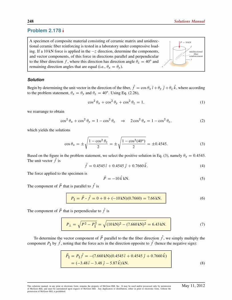
248 Solutions Manual
Problem 2.178
A specimen of composite material consisting of ceramic matrix and unidirec-tional ceramic fiber reinforcing is tested in a laboratory under compressive load-ing. If a 10 kN force is applied in the �´ direction, determine the components,and vector components, of this force in directions parallel and perpendicularto the fiber direction f , where this direction has direction angle �´ D 40
ı andremaining direction angles that are equal (i.e., �x D �y).
Solution
Begin by determining the unit vector in the direction of the fiber, Of D cos �x O{C�y O|C�´Ok, where according
to the problem statement, �x D �y and �´ D 40ı. Using Eq. (2.26),
cos2 �x C cos2 �y C cos2 �´ D 1; (1)
we rearrange to obtain
cos2 �x C cos2 �y D 1 � cos2 �´ ) 2 cos2 �x D 1 � cos2 �´; (2)
which yields the solutions
cos �x D ˙
s1 � cos2 �´
2D ˙
s1 � cos2.40ı/
2D ˙0:4545: (3)
Based on the figure in the problem statement, we select the positive solution in Eq. (3), namely �x D 0:4545.The unit vector Of is
Of D 0:4545 O{ C 0:4545 O| C 0:7660 Ok: (4)
The force applied to the specimen isEP D �10 Ok kN: (5)
The component of EP that is parallel to Of is
Pk D EP � Of D 0C 0C .�10 kN/.0:7660/ D 7:66 kN: (6)
The component of EP that is perpendicular to Of is
P? DqP 2 � P 2
kD
q.10 kN/2 � .7:660 kN/2 D 6:43 kN: (7)
To determine the vector component of EP parallel to the the fiber direction Of , we simply multiply thecomponent Pk by Of , noting that the force acts in the direction opposite to Of (hence the negative sign):
EPk D Pk Of D �.7:660 kN/.0:4545 O{ C 0:4545 O| C 0:7660 Ok/
D .�3:48 O{ � 3:48 O| � 5:87 Ok/ kN: (8)
May 11, 2012This solutions manual, in any print or electronic form, remains the property of McGraw-Hill, Inc. It may be used and/or possessed only by permissionof McGraw-Hill, and must be surrendered upon request of McGraw-Hill. Any duplication or distribution, either in print or electronic form, without thepermission of McGraw-Hill, is prohibited.

Statics 2e 249
The vector component of EP perpendicular to the the fiber direction is then
EP? D EP � EPk D .�10 Ok/ kN � .�3:482 O{ � 3:482 O| � 5:868 Ok/ kN
D .3:48 O{ C 3:48 O| � 4:13 Ok/ kN: (9)
As a partial check of accuracy, we evaluate the magnitudes of Eqs. (8) and (9) to obtain
j EPkj D
q.�3:482/2 C .�3:482/2 C .�5:868/2 kN D 7:660 kN; (10)
j EP?j D
q.3:482/2 C .3:482/2 C .�4:132/2 kN D 6:428 kN; (11)
and we observe that these values agree with the components found in Eqs. (6) and (7), respectively.
May 11, 2012This solutions manual, in any print or electronic form, remains the property of McGraw-Hill, Inc. It may be used and/or possessed only by permissionof McGraw-Hill, and must be surrendered upon request of McGraw-Hill. Any duplication or distribution, either in print or electronic form, without thepermission of McGraw-Hill, is prohibited.

250 Solutions Manual
Problem 2.179
An automobile body panel is subjected to a force EF from a stiffening strut.Assuming that region ABC of the panel is planar, determine the components,and vector components, of EF in the directions normal and parallel to the panel.
Solution
The following vectors are obtained from the figure in the problem statement:
ErBC D�.0 � 0/ O{ C .0 � 180/ O| C .120 � 0/ Ok
�mm D .0 O{ � 180 O| C 120 Okmm; (1)
ErBA D�.130 � 0/ O{ C .0 � 180/ O| C .60 � 0/ Ok
�mm D .130 O{ � 180 O| C 60 Ok/mm: (2)
A vector En in the normal direction to the panel is given by
En D ErBC � ErBA D
ˇˇ O{ O| Ok
0 �180 120
130 �180 60
ˇˇ mm2 (3)
D˚Œ.�180/.60/ � .120/.�180/� O{ � Œ.0/.60/ � .120/.130/� O|
C Œ.0/.�180/ � .�180/.130/� Ok
mm2 (4)
D .108 � 102O{ C 156 � 102
O| C 234 � 102 Ok/mm2; (5)
n D
q.108 � 102/2 C .156 � 102/2 C .234 � 102/2 mm2
D 301:3�102 mm2: (6)
The unit vector in the En direction is
On DEn
nD
�108 � 102 O{ C 156 � 102 O| C 234 � 102 Ok
�mm2
301:3�102 mm2 D 0:3585 O{ C 0:5178 O| C 0:7767 Ok: (7)
The component of EF normal to the panel is found using the dot product as
F? D EF � On D .40N/.0:3585/C .�80N/.0:5178/C .�80N/.0:7767/ D �89:2N: (8)
The magnitude of the force EF is
F D
q.40N/2 C .�80N/2 C .�80N/2 D 120N: (9)
Hence, the component of the force tangent to the surface of the panel is
Fk D
qF 2 � F 2
?D
q.120N/2 � .�89:23N/2 D 80:2N: (10)
The vector component of EF in the direction normal to the panel is given by
EF? D F? On D .�89:23N/.0:3585 O{ C 0:5178 O| C 0:7767 Ok/
D .�32:0 O{ � 46:2 O| � 69:3 Ok/N; (11)
May 11, 2012This solutions manual, in any print or electronic form, remains the property of McGraw-Hill, Inc. It may be used and/or possessed only by permissionof McGraw-Hill, and must be surrendered upon request of McGraw-Hill. Any duplication or distribution, either in print or electronic form, without thepermission of McGraw-Hill, is prohibited.

Statics 2e 251
and the vector component of EF in the direction tangent to the panel is given by
EFk D EF � EF? D .40 O{ � 80 O| � 80 Ok/N � .�31:99 O{ � 46:20 O| � 69:31 Ok/N
D .72:0 O{ � 33:8 O| � 10:7 Ok/N: (12)
As a partial check of accuracy, we evaluate the magnitudes of Eqs. (11) and (12) to obtain
j EF?j D
q.�31:99/2 C .�46:20/2 C .�69:31/2 N D 89:2N; (13)
j EFkj D
q.71:99/2 C .�33:80/2 C .�10:69/2 N D 80:2N; (14)
and we observe that these values agree with the absolute values of the components found in Eqs. (8) and (10),respectively.
May 11, 2012This solutions manual, in any print or electronic form, remains the property of McGraw-Hill, Inc. It may be used and/or possessed only by permissionof McGraw-Hill, and must be surrendered upon request of McGraw-Hill. Any duplication or distribution, either in print or electronic form, without thepermission of McGraw-Hill, is prohibited.

252 Solutions Manual
Problem 2.180
The steering wheel and gearshift lever of an automobile are shown. Points A, C ,and B lie on the axis of the steering column, where point A is at the origin ofthe coordinate system, point B has the coordinates B .�120; 0;�50/mm, andpoint C is 60mm from point A. The gearshift lever from C to D has 240mmlength and the direction angles given below.
(a) Two of the direction angles for the position vector from point C to Dare �y D 50ı and �´ D 60ı. Knowing that this position vector has anegative x component, determine �x .
(b) Determine the unit vector Or that is perpendicular to directions AB andCD such that this vector has a positive ´ component.
(c) If the force applied to the gearshift lever is EP D .�6 O{ � 4 O| C 12 Ok/N,determine the component of EP , namely Pr , in the direction of Or .
Solution
Part (a) The y and ´ direction angles are given, and the remaining direction angle must satisfy
.cos �x/2C .cos 50ı/2 C .cos 60ı/2 D 1: (1)
Solving for �x provides
cos �x D˙
q1 � .cos 50ı/2 � .cos 60ı/2 (2)
�x D cos�1˙
q1 � .cos 50ı/2 � .cos 60ı/2 (3)
D 54:52ı; 125:5ı: (4)
Since the position vector from C to D, namely ErCD , has a negative x component, the correct direction angleis
�x D 125:5ı: (5)
Part (b) Using the coordinates of points A and B given in the problem statement, and the direction anglesfrom Part (a),
ErAB D .�120 O{ � 0 O| � 50 Ok/ mm, (6)
ErCD D .240 mm/.cos 125:5ı O{ C cos 50ı O| C cos 60ı Ok/ (7)
D .�139:3 O{ C 154:3 O| C 120 Ok/ mm. (8)
The vector Er that is perpendicular to both ErAB and ErCD , where we use the right hand rule to select the orderof the vectors in the cross product so that the result will have a positive ´ component, is
May 11, 2012This solutions manual, in any print or electronic form, remains the property of McGraw-Hill, Inc. It may be used and/or possessed only by permissionof McGraw-Hill, and must be surrendered upon request of McGraw-Hill. Any duplication or distribution, either in print or electronic form, without thepermission of McGraw-Hill, is prohibited.

Statics 2e 253
Er D ErCD � ErAB D
ˇˇ O{ O| Ok
�139:3 154:3 120
�120 0 �50
ˇˇmm2 (9)
D
nO{�.154:3/.�50/ � .120/.0/
�� O|
�.�139:3/.�50/ � .120/.�120/
�C Ok
�.�139:3/.0/ � .154:3/.�120/
�omm2 (10)
D .�7713 O{ � 21;364 O| C 18;512 Ok/ mm2: (11)
The unit vector in the direction of Er is
Or DEr
rD.�7713 O{ � 21;364 O| C 18;512 Ok/ mm2
29;303 mm2(12)
D �0:2632 O{ � 0:7291 O| C 0:6318 Ok: (13)
Part (c)
Pr D EP � Or D .�6 N/.�0:2632/C .�4 N/.�0:7291/C .12 N/.0:6318/
D 12:08 N: (14)
Some checks of solution accuracy:
� Verify that �x D 125:5ı; �y D 50ı; and �´ D 60ı are indeed direction angles by checking thatEq. (1) is satisfied.
� Verify that Eq. (8) has 240 mm magnitude.
� Verify that Er given by Eq. (11) is orthogonal to both ErAB and ErCD by checking that Er � ErAB D 0 andEr � ErCD D 0.
� Verify that Or in Eq. (13) is a unit vector.
May 11, 2012This solutions manual, in any print or electronic form, remains the property of McGraw-Hill, Inc. It may be used and/or possessed only by permissionof McGraw-Hill, and must be surrendered upon request of McGraw-Hill. Any duplication or distribution, either in print or electronic form, without thepermission of McGraw-Hill, is prohibited.

254 Solutions Manual
Problem 2.181
The steering wheel and gearshift lever of an automobile are shown. Points A, C ,and B lie on the axis of the steering column, where point A is at the origin ofthe coordinate system, point B has the coordinates B .�120; 0;�50/mm, andpoint C is 60mm from point A. The gearshift lever from C to D has 240mmlength and the direction angles given below.
(a) Two of the direction angles for the position vector from point C to Dare �y D 45ı and �´ D 70ı. Knowing that this position vector has anegative x component, determine �x .
(b) Determine the unit vector Or that is perpendicular to directions AB andCD such that this vector has a positive ´ component.
(c) If the force applied to the gear shift lever is EP D .�9 O{ � 6 O| C 18 Ok/N,determine the component of EP , namely Pr , in the direction of Or .
Solution
Part (a) The y and ´ direction angles are given, and the remaining direction angle must satisfy
.cos �x/2C .cos 45ı/2 C .cos 70ı/2 D 1: (1)
Solving for �x provides
cos �x D˙
q1 � .cos 45ı/2 � .cos 70ı/2 (2)
�x D cos�1˙
q1 � .cos 45ı/2 � .cos 70ı/2 (3)
D 51:76ı; 128:2ı: (4)
Since the position vector from C to D, namely ErCD , has a negative x component, the correct direction angleis
�x D 128:2ı: (5)
Part (b) Using the coordinates of points A and B given in the problem statement, and the direction anglesfrom Part (a),
ErAB D .�120 O{ � 0 O| � 50 Ok/ mm, (6)
ErCD D .240 mm/.cos 128:2ı O{ C cos 45ı j C cos 70ı Ok/ (7)
D .�148:5 O{ C 169:7 O| C 82:08 Ok/ mm. (8)
The vector Er that is perpendicular to both ErAB and ErCD , where we use the right hand rule to select the orderof the vectors in the cross product so that the result will have positive ´ component, is
May 11, 2012This solutions manual, in any print or electronic form, remains the property of McGraw-Hill, Inc. It may be used and/or possessed only by permissionof McGraw-Hill, and must be surrendered upon request of McGraw-Hill. Any duplication or distribution, either in print or electronic form, without thepermission of McGraw-Hill, is prohibited.

Statics 2e 255
Er D ErCD � ErAB D
ˇˇ O{ O| Ok
�148:5 169:7 82:08
�120 0 �50
ˇˇmm2 (9)
D
nO{�.169:7/.�50/ � .82:08/.0/
�� O|
�.�148:5/.�50/ � .82:08/.�120/
�C Ok
�.�148:5/.0/ � .169:7/.�120/
�omm2 (10)
D .�8485 O{ � 17;277 O| C 20;365 Ok/ mm2: (11)
The unit vector in the direction of Er is
Or DEr
rD.�8485 O{ � 17;277 O| C 20;365 Ok/ mm2
28;022 mm2(12)
D �0:3028 O{ � 0:6166 O| C 0:7268 Ok: (13)
Part (c)
Pr D EP � Or D .�9 N/.�0:3028/C .�6 N/.�0:6166/C .18 N/.0:7268/
D 19:51 N: (14)
Some checks of solution accuracy:
� Verify that �x D 128:2ı; �y D 45ı; and �´ D 70ı are indeed direction angles by checking thatEq. (1) is satisfied.
� Verify that Eq. (8) has 240 mm magnitude.
� Verify that Er given by Eq. (11) is orthogonal to both ErAB and ErCD by checking that Er � ErAB D 0 andEr � ErCD D 0.
� Verify that Or in Eq. (13) is a unit vector.
May 11, 2012This solutions manual, in any print or electronic form, remains the property of McGraw-Hill, Inc. It may be used and/or possessed only by permissionof McGraw-Hill, and must be surrendered upon request of McGraw-Hill. Any duplication or distribution, either in print or electronic form, without thepermission of McGraw-Hill, is prohibited.

256 Solutions Manual
Problem 2.182
An I beam is positioned from points A to B . Because its strength and deforma-tion properties for bending about an axis through the web of the cross sectionare different than those for bending about an axis parallel to the flanges, it isnecessary to also characterize these directions. This can be accomplished byspecifying just one of the direction angles for the direction of the web fromA to C , which is perpendicular to line AB , plus the octant of the coordinatesystem in which line AC lies.
(a) If direction angle �´ D 30ı for line AC , determine the remaining direc-
tion angles for this line.
(b) Determine the unit vector in the direction perpendicular to the web of thebeam (i.e., perpendicular to lines AB and AC ).
Solution
Part (a) The two unknowns to be determined are the x and y direction angles for line AC , namely �x and�y . It will be necessary to write two equation so that these unknowns may be determined. Our strategy willbe to write an expression requiring line AC to be perpendicular to line AB (we will use OrAC � ErAB D 0),and we will write an expression requiring the squares of the direction cosines to sum to one. Based on theproblem description, the following position vectors may be written
OrAC D cos �x O{ C cos �y O| C cos �´Ok;
D cos �x O{ C cos �y O| C cos 30ı Ok;
D cos �x O{ C cos �y O| C 0:8660 Ok; (1)
ErAB D .�8 O{ C 6 O| C 0 Ok/ ft; (2)
rAB D 10 ft: (3)
Note that OrAC is a unit vector, while ErAB is not. As described in the problem statement, vectors OrAC and ErAB
are orthogonal, hence
OrAC � ErAB D 0
cos �x.�8 ft/C cos �y.6 ft/C .0:8660/.0/ D 0: (4)
Equation (4) givescos �x D
34
cos �y : (5)
The three direction angles must also satisfy
cos2 �x C cos2 �y C cos2 30ı D 1
cos2 �x C cos2 �y C .0:8660/2D 1: (6)
Substituting Eq. (5) into Eq. (6) gives�34
cos �y
�2C cos2 �y C .0:8660/
2D 1 (7)
) cos �y D ˙
s1 � .0:8660/2
.3=4/2 C 1D ˙0:4000 (8)
May 11, 2012This solutions manual, in any print or electronic form, remains the property of McGraw-Hill, Inc. It may be used and/or possessed only by permissionof McGraw-Hill, and must be surrendered upon request of McGraw-Hill. Any duplication or distribution, either in print or electronic form, without thepermission of McGraw-Hill, is prohibited.

Statics 2e 257
) �y D 66:42ı; 113:6ı: (9)
Referring to the figure in the problem statement, the position vector OrAC has negative y component, thus weselect the negative solution for cos �y in Eq. (8) and the corresponding value of �y in Eq. (9), i.e.,
cos �y D �0:4000 ) �y D 114ı. (10)
Substituting cos �y D �0:4000 into Eq. (5) provides
cos �x D34.�0:4000/ D �0:3000 ) �x D 107
ı. (11)
Part (b) The unit vector Or? that is perpendicular to AB and AC is found using the cross product as
Or? DErAB
rAB� OrAC D
ˇˇ O{ O| Ok
�8=10 6=10 0
�0:3000 �0:4000 0:8600
ˇˇ (12)
D Œ.0:6/.0:8600/ � 0� O{ � Œ.�0:8/.0:8600/ � 0� O| C Œ.�0:8/.�0:4/ � .0:6/.�0:3/� Ok (13)
D 0:520 O{ C 0:693 O| C 0:500 Ok. (14)
Note that an acceptable answer is also obtained if the vectors in the cross product of Eq. (12) are interchanged,thus the following is also a correct answer
Or? D �0:520 O{ � 0:693 O| � 0:500 Ok: (15)
May 11, 2012This solutions manual, in any print or electronic form, remains the property of McGraw-Hill, Inc. It may be used and/or possessed only by permissionof McGraw-Hill, and must be surrendered upon request of McGraw-Hill. Any duplication or distribution, either in print or electronic form, without thepermission of McGraw-Hill, is prohibited.
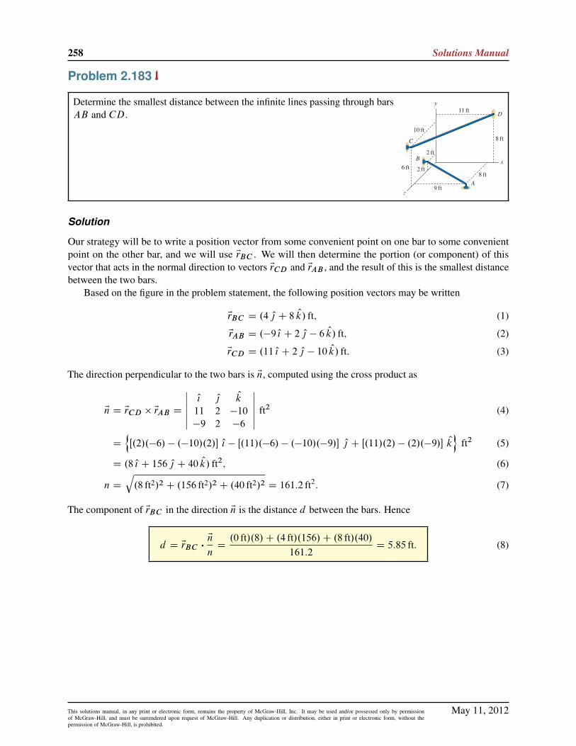
258 Solutions Manual
Problem 2.183
Determine the smallest distance between the infinite lines passing through barsAB and CD.
Solution
Our strategy will be to write a position vector from some convenient point on one bar to some convenientpoint on the other bar, and we will use ErBC . We will then determine the portion (or component) of thisvector that acts in the normal direction to vectors ErCD and ErAB , and the result of this is the smallest distancebetween the two bars.
Based on the figure in the problem statement, the following position vectors may be written
ErBC D .4 O| C 8 Ok/ ft; (1)
ErAB D .�9 O{ C 2 O| � 6 Ok/ ft; (2)
ErCD D .11 O{ C 2 O| � 10 Ok/ ft: (3)
The direction perpendicular to the two bars is En, computed using the cross product as
En D ErCD � ErAB D
ˇˇ O{ O| Ok
11 2 �10
�9 2 �6
ˇˇ ft2 (4)
D
nŒ.2/.�6/ � .�10/.2/� O{ � Œ.11/.�6/ � .�10/.�9/� O| C Œ.11/.2/ � .2/.�9/� Ok
oft2 (5)
D .8 O{ C 156 O| C 40 Ok/ ft2; (6)
n D
q.8 ft2/2 C .156 ft2/2 C .40 ft2/2 D 161:2 ft2: (7)
The component of ErBC in the direction En is the distance d between the bars. Hence
d D ErBC �En
nD.0 ft/.8/C .4 ft/.156/C .8 ft/.40/
161:2D 5:85 ft: (8)
May 11, 2012This solutions manual, in any print or electronic form, remains the property of McGraw-Hill, Inc. It may be used and/or possessed only by permissionof McGraw-Hill, and must be surrendered upon request of McGraw-Hill. Any duplication or distribution, either in print or electronic form, without thepermission of McGraw-Hill, is prohibited.
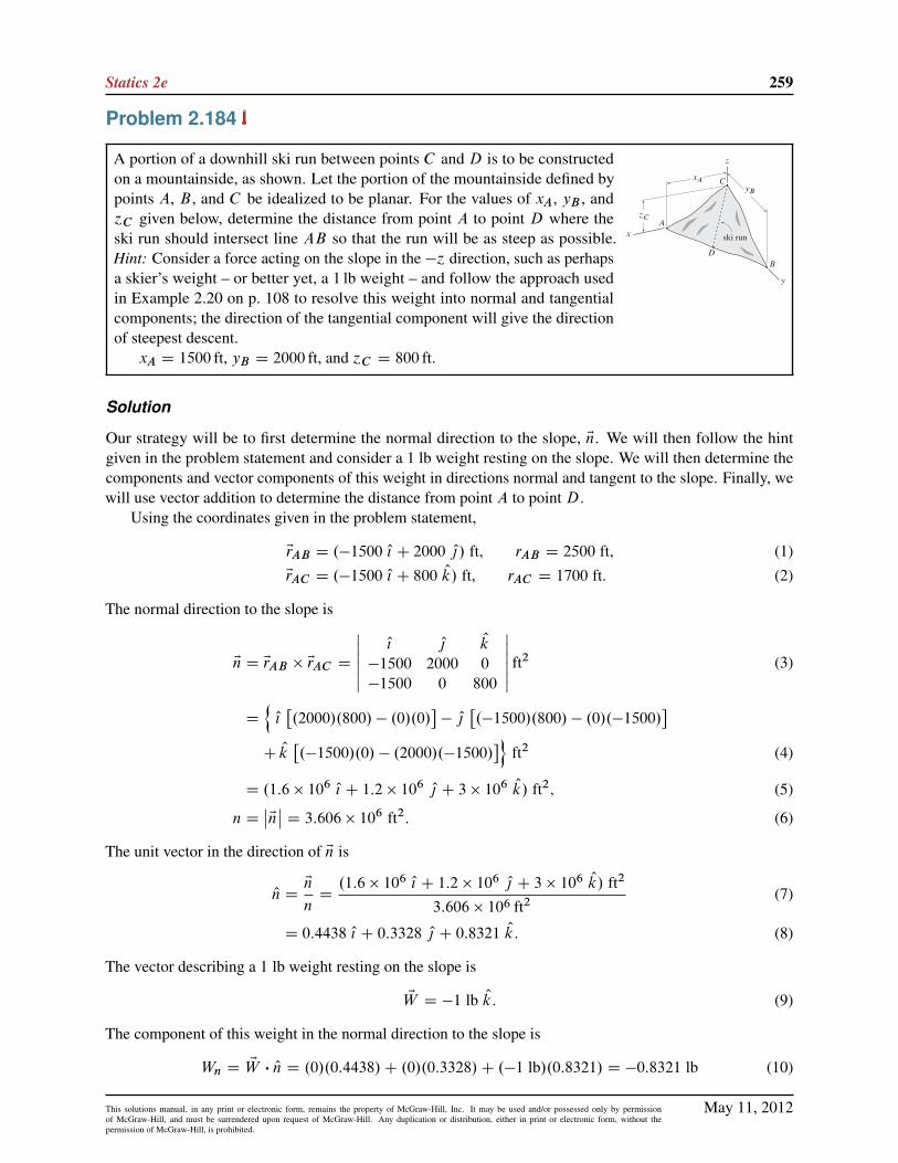
Statics 2e 259
Problem 2.184
A portion of a downhill ski run between points C and D is to be constructedon a mountainside, as shown. Let the portion of the mountainside defined bypoints A, B , and C be idealized to be planar. For the values of xA, yB , and´C given below, determine the distance from point A to point D where theski run should intersect line AB so that the run will be as steep as possible.Hint: Consider a force acting on the slope in the �´ direction, such as perhapsa skier’s weight – or better yet, a 1 lb weight – and follow the approach usedin Example 2.20 on p. 108 to resolve this weight into normal and tangentialcomponents; the direction of the tangential component will give the directionof steepest descent.
xA D 1500 ft, yB D 2000 ft, and ´C D 800 ft.
Solution
Our strategy will be to first determine the normal direction to the slope, En. We will then follow the hintgiven in the problem statement and consider a 1 lb weight resting on the slope. We will then determine thecomponents and vector components of this weight in directions normal and tangent to the slope. Finally, wewill use vector addition to determine the distance from point A to point D.
Using the coordinates given in the problem statement,
ErAB D .�1500 O{ C 2000 O|/ ft, rAB D 2500 ft, (1)
ErAC D .�1500 O{ C 800 Ok/ ft, rAC D 1700 ft. (2)
The normal direction to the slope is
EnD ErAB � ErAC D
ˇˇ O{ O| Ok
�1500 2000 0
�1500 0 800
ˇˇ ft2 (3)
D
nO{�.2000/.800/ � .0/.0/
�� O|
�.�1500/.800/ � .0/.�1500/
�C Ok
�.�1500/.0/ � .2000/.�1500/
�oft2 (4)
D .1:6 � 106O{ C 1:2 � 106
O| C 3 � 106 Ok/ ft2; (5)
nDˇEnˇD 3:606 � 106 ft2: (6)
The unit vector in the direction of En is
OnDEn
nD.1:6 � 106 O{ C 1:2 � 106 O| C 3 � 106 Ok/ ft2
3:606 � 106 ft2(7)
D 0:4438 O{ C 0:3328 O| C 0:8321 Ok: (8)
The vector describing a 1 lb weight resting on the slope is
EW D �1 lb Ok: (9)
The component of this weight in the normal direction to the slope is
Wn D EW � On D .0/.0:4438/C .0/.0:3328/C .�1 lb/.0:8321/ D �0:8321 lb (10)
May 11, 2012This solutions manual, in any print or electronic form, remains the property of McGraw-Hill, Inc. It may be used and/or possessed only by permissionof McGraw-Hill, and must be surrendered upon request of McGraw-Hill. Any duplication or distribution, either in print or electronic form, without thepermission of McGraw-Hill, is prohibited.

260 Solutions Manual
The vector component of the weight in the normal direction is
EWn DWn On D .�0:8321 lb/.0:4438 O{ C 0:3328 O| C 0:8321 Ok/ (11)
D .�0:3692 O{ � 0:2769 O| � 0:6923 Ok/ lb: (12)
The vector component of the weight that is tangent to the slope is EWt , and noting that EW D EWt C EWn, wehave
EWt D EW � EWn (13)
D �1 lb Ok � .�0:3692 O{ � 0:2769 O| � 0:6923 Ok/ lb (14)
D .0:3692 O{ C 0:2769 O| � 0:3077 Ok/ lb, (15)
Wt D
ˇEWt
ˇD
q.0:3692 lb)2
C .0:2769 lb)2C .�0:3077 lb)2
D 0:5547 lb. (16)
As a partial check of solution accuracy, we use the Pythagorean theoremW DqW 2
t CW2
n;whereW D 1 lb
and Wn is given by Eq. (10), to write
Wt D
qW 2 �W 2
nD
q.1 lb/2 � .�0:8321 lb/2 D 0:5547 lb; (17)
and we observe that this result agrees with Eq. (16).The unit vector in the direction of EWt is
Ot DEWt
WtD.0:3692 O{ C 0:2769 O| � 0:3077 Ok/ lb
0:5547 lb(18)
D 0:6656 O{ C 0:4992 O| � 0:5547 Ok: (19)
The position vector from C to D is
ErCD D rCD Ot D rCD.0:6656 O{ C 0:4992 O| � 0:5547 Ok/: (20)
We then use vector addition to write
ErCD D ErCA C ErAD D �ErAC C rADErAB
rAB; (21)
which becomes
rCD.0:6656 O{ C 0:4992 O| � 0:5547 Ok/ D �.�1500 O{ C 800 Ok/ ftC rAD.�1500 O{ C 2000 O|/ ft
2500 ft: (22)
Equating terms that multiply O{; O|; and Ok gives the following three scalar equations
rCD.0:6656/D 1500 ft � rAD1500
2500; (23)
rCD.0:4992/D rAD2000
2500; (24)
rCD.�0:5547/D �800 ft. (25)
Solving Eq. (25) for rCD and then solving Eq. (24) for rAD provides
rCD D 1442 ft and rAD D 900 ft. (26)
Note that these solutions also satisfy Eq. (23). Thus, the distance from point A to point D is 900 ft.
May 11, 2012This solutions manual, in any print or electronic form, remains the property of McGraw-Hill, Inc. It may be used and/or possessed only by permissionof McGraw-Hill, and must be surrendered upon request of McGraw-Hill. Any duplication or distribution, either in print or electronic form, without thepermission of McGraw-Hill, is prohibited.

Statics 2e 261
Alternative solution Rather than using the hint given in the prob-lem statement, a straightforward, although perhaps less intuitive,alternative solution can developed by noting that the run will besteepest when lines AB and CD are perpendicular, as shown atthe right. With the dimensions given in the problem statement, thefollowing position vectors may be written.
ErAC D .�1500 O{ C 800 Ok/ ft; (27)
ErAB D .�1500 O{ C 2000 O|/ ft; rAB D 2500 ft: (28)
The distance rAD is then obtained using
rAD D ErAC �ErAB
rABD.�1500/.�1500/C .0/.2000/C .800/.0/
2500D 900 ft: (29)
Thus, the distance from point A to point D is 900 ft.
May 11, 2012This solutions manual, in any print or electronic form, remains the property of McGraw-Hill, Inc. It may be used and/or possessed only by permissionof McGraw-Hill, and must be surrendered upon request of McGraw-Hill. Any duplication or distribution, either in print or electronic form, without thepermission of McGraw-Hill, is prohibited.

262 Solutions Manual
Problem 2.185
A portion of a downhill ski run between points C and D is to be constructedon a mountainside, as shown. Let the portion of the mountainside defined bypoints A, B , and C be idealized to be planar. For the values of xA, yB , and´C given below, determine the distance from point A to point D where theski run should intersect line AB so that the run will be as steep as possible.Hint: Consider a force acting on the slope in the �´ direction, such as perhapsa skier’s weight – or better yet, a 1 lb weight – and follow the approach usedin Example 2.20 on p. 108 to resolve this weight into normal and tangentialcomponents; the direction of the tangential component will give the directionof steepest descent.
xA D 1200 ft, yB D 1600 ft, and ´C D 900 ft.
Solution
Our strategy will be to first determine the normal direction to the slope, En. We will then follow the hintgiven in the problem statement and consider a 1 lb weight resting on the slope. We will then determine thecomponents and vector components of this weight in directions normal and tangent to the slope. Finally, wewill use vector addition to determine the distance from point A to point D.
Using the coordinates given in the problem statement,
ErAB D .�1200 O{ C 1600 O|/ ft, rAB D 2000 ft, (1)
ErAC D .�1200 O{ C 900 Ok/ ft, rAC D 1500 ft. (2)
The normal direction to the slope is
EnD ErAB � ErAC D
ˇˇ O{ O| Ok
�1200 1600 0
�1200 0 900
ˇˇ ft2 (3)
D
nO{�.1600/.900/ � .0/.0/
�� O|
�.�1200/.900/ � .0/.�1200/
�C Ok
�.�1200/.0/ � .1600/.�1200/
�oft2 (4)
D .1:44 � 106O{ C 1:08 � 106
O| C 1:92 � 106 Ok/ ft2; (5)
nDˇEnˇD 2:632 � 106 ft2: (6)
The unit vector in the direction of En is
OnDEn
nD.1:44 � 106 O{ C 1:08 � 106 O| C 1:92 � 106 Ok/ ft2
2:632 � 106 ft2(7)
D 0:5472 O{ C 0:4104 O| C 0:7295 Ok: (8)
The vector describing a 1 lb weight resting on the slope is
EW D �1 lb Ok: (9)
The component of this weight in the normal direction to the slope is
Wn D EW � On D .0/.0:5472/C .0/.0:4104/C .�1 lb/.0:7295/ D �0:7295 lb. (10)
May 11, 2012This solutions manual, in any print or electronic form, remains the property of McGraw-Hill, Inc. It may be used and/or possessed only by permissionof McGraw-Hill, and must be surrendered upon request of McGraw-Hill. Any duplication or distribution, either in print or electronic form, without thepermission of McGraw-Hill, is prohibited.

Statics 2e 263
The vector component of the weight in the normal direction is
EWn DWn On D .�0:7295 lb/.0:5472 O{ C 0:4104 O| C 0:7295 Ok/ (11)
D .�0:3992 O{ � 0:2994 O| � 0:5322 Ok/ lb: (12)
The vector component of the weight that is tangent to the slope is EWt , and noting that EW D EWt C EWn, wehave
EWt D EW � EWn (13)
D �1 lb Ok � .�0:3992 O{ � 0:2994 O| � 0:5332 Ok/ lb (14)
D .0:3992 O{ C 0:2994 O| � 0:4678 Ok/ lb, (15)
Wt D
ˇEWt
ˇD
q.0:3992 lb)2
C .0:2994 lb)2C .�0:4678 lb)2
D 0:6839 lb. (16)
As a partial check of solution accuracy, we use the Pythagorean theoremW DqW 2
t CW2
n, whereW D 1 lb
and Wn is given by Eq. (10), to write
Wt D
qW 2 �W 2
nD
q.1 lb/2 � .�0:7295 lb/2 D 0:6839 lb; (17)
and we observe that this result agrees with Eq. (16).The unit vector in the direction of EWt is
Ot DEWt
WtD.0:3992 O{ C 0:2994 O| � 0:4678 Ok/ lb
0:6839 lb(18)
D 0:5836 O{ C 0:4377 O| � 0:6839 Ok: (19)
The position vector from C to D is
ErCD D rCD Ot D rCD.0:5836 O{ C 0:4377 O| � 0:6839 Ok/: (20)
We then use vector addition to write
ErCD D ErCA C ErAD D �ErAC C rADErAB
rAB; (21)
which becomes
rCD.0:5836 O{ C 0:4377 O| � 0:6839 Ok/ D �.�1200 O{ C 900 Ok/ ftC rAD.�1200 O{ C 1600 O|/ ft
2000 ft: (22)
Equating terms that multiply O{; O|; and Ok gives the following three scalar equations
rCD.0:5836/D 1200 ft � rAD1200
2000; (23)
rCD.0:4377/D rAD1600
2000; (24)
rCD.�0:6839/D �900 ft. (25)
Solving Eq. (25) for rCD and then solving Eq. (24) for rAD provides
rCD D 1316 ft and rAD D 720 ft. (26)
Note that these solutions also satisfy Eq. (23). Thus, the distance from point A to point D is 720 ft.
May 11, 2012This solutions manual, in any print or electronic form, remains the property of McGraw-Hill, Inc. It may be used and/or possessed only by permissionof McGraw-Hill, and must be surrendered upon request of McGraw-Hill. Any duplication or distribution, either in print or electronic form, without thepermission of McGraw-Hill, is prohibited.
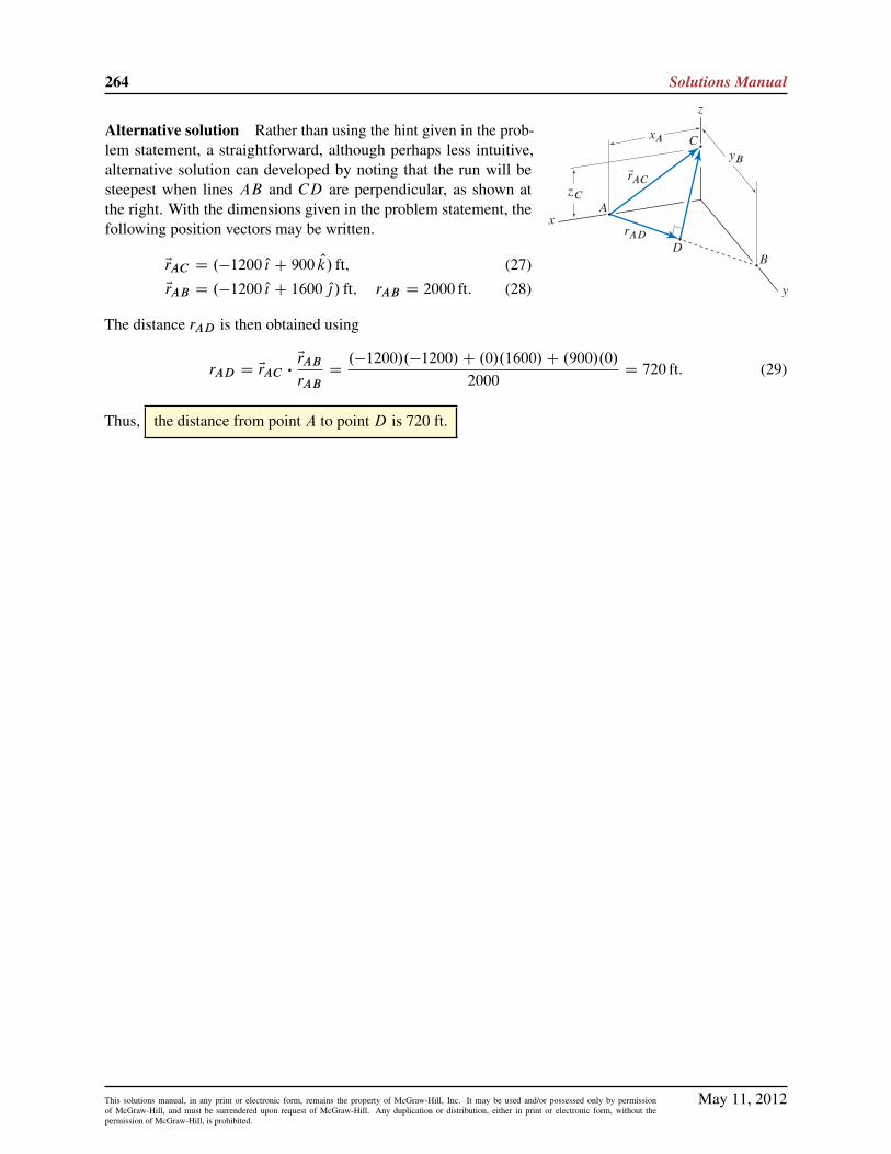
264 Solutions Manual
Alternative solution Rather than using the hint given in the prob-lem statement, a straightforward, although perhaps less intuitive,alternative solution can developed by noting that the run will besteepest when lines AB and CD are perpendicular, as shown atthe right. With the dimensions given in the problem statement, thefollowing position vectors may be written.
ErAC D .�1200 O{ C 900 Ok/ ft; (27)
ErAB D .�1200 O{ C 1600 O|/ ft; rAB D 2000 ft: (28)
The distance rAD is then obtained using
rAD D ErAC �ErAB
rABD.�1200/.�1200/C .0/.1600/C .900/.0/
2000D 720 ft: (29)
Thus, the distance from point A to point D is 720 ft.
May 11, 2012This solutions manual, in any print or electronic form, remains the property of McGraw-Hill, Inc. It may be used and/or possessed only by permissionof McGraw-Hill, and must be surrendered upon request of McGraw-Hill. Any duplication or distribution, either in print or electronic form, without thepermission of McGraw-Hill, is prohibited.
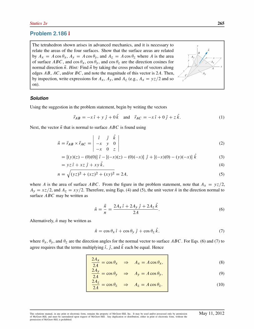
Statics 2e 265
Problem 2.186
The tetrahedron shown arises in advanced mechanics, and it is necessary torelate the areas of the four surfaces. Show that the surface areas are relatedby Ax D A cos �x , Ay D A cos �y , and A´ D A cos �´ where A is the areaof surface ABC , and cos �x , cos �y , and cos �´ are the direction cosines fornormal direction En. Hint: Find En by taking the cross product of vectors alongedges AB , AC , and/or BC , and note the magnitude of this vector is 2A. Then,by inspection, write expressions for Ax , Ay , and A´ (e.g., Ax D y´=2 and soon).
Solution
Using the suggestion in the problem statement, begin by writing the vectors
ErAB D �x O{ C y O| C 0 Ok and ErAC D �x O{ C 0 O| C ´ Ok: (1)
Next, the vector En that is normal to surface ABC is found using
En D ErAB � ErAC D
ˇˇ O{ O| Ok
�x y 0
�x 0 ´
ˇˇ (2)
D Œ.y/.´/ � .0/.0/� O{ � Œ.�x/.´/ � .0/.�x/� O| C Œ.�x/.0/ � .y/.�x/� Ok (3)
D y´ O{ C x´ O| C xy Ok; (4)
n D
q.y´/2 C .x´/2 C .xy/2 D 2A; (5)
where A is the area of surface ABC . From the figure in the problem statement, note that Ax D y´=2,Ay D x´=2, and A´ D xy=2. Therefore, using Eqs. (4) and (5), the unit vector On in the direction normal tosurface ABC may be written as
On DEn
nD2Ax O{ C 2Ay O| C 2A´
Ok
2A: (6)
Alternatively, On may be written as
On D cos �x O{ C cos �y O| C cos �´Ok; (7)
where �x , �y , and �´ are the direction angles for the normal vector to surface ABC . For Eqs. (6) and (7) toagree requires that the terms multiplying O{, O| , and Ok each be equal. Hence
2Ax
2AD cos �x ) Ax D A cos �x;
2Ay
2AD cos �y ) Ay D A cos �y ;
2A´
2AD cos �´ ) A´ D A cos �´:
(8)
(9)
(10)
May 11, 2012This solutions manual, in any print or electronic form, remains the property of McGraw-Hill, Inc. It may be used and/or possessed only by permissionof McGraw-Hill, and must be surrendered upon request of McGraw-Hill. Any duplication or distribution, either in print or electronic form, without thepermission of McGraw-Hill, is prohibited.