Static load test method statement cm - ms- bw - 003
19
Doc. Title Method Statement for Static and PDA Load Test of pile for Building TOA-TOYO JOINT VENTURE Doc. No CM – MS – BW - 003 Rev. No. 0 Date July, 2010 Construction of Port Facilities and Buildings for Cai Mep International Container Terminal CAI MEP INTERNATIONAL CONTAINER TERMINAL METHOD STATEMENT FOR STATIC AND PDA LOAD TEST OF PILE FOR BUILDING Page 1
-
Upload
minh-bui-si -
Category
Documents
-
view
626 -
download
3
Transcript of Static load test method statement cm - ms- bw - 003

Doc. Title Method Statement for Static and PDA Load Test of pile for Building TOA-TOYO JOINT VENTURE
Doc. No CM – MS – BW - 003 Rev. No. 0 Date July, 2010
Construction of Port Facilities and Buildings for Cai Mep International Container Terminal
CAI MEP INTERNATIONAL CONTAINER TERMINAL
METHOD STATEMENT FOR STATIC AND PDA LOAD TESTOF PILE FOR BUILDING
Page 1

Doc. Title Method Statement for Static and PDA Load Test of pile for Building TOA-TOYO JOINT VENTURE
Doc. No CM – MS – BW - 003 Rev. No. 0 Date July, 2010
Construction of Port Facilities and Buildings for Cai Mep International Container Terminal
TABLE OF CONTENTS
I INTRODUCTION 3
II. STATIC LOAD TEST 3
1. SPECIFICATIONS OF TEST PILE 3
2. TEST PURPOSE 4
3. TEST METHOD 4
4. TEST EQUIP MENT 4
5. SETTLEMENT 6
6. PREPARATION 6
7. TEST PROCEDURE 7
8. TEST RESULT 12
9. CONCLUSION AND RECOMMENDATION 13
III. PDA TEST 13
1. TEST PURPOSE 13
2. TEST PRINCIPLE 13
3. TEST EQUIP MENT 13
4. TEST PROCEDURE 14
5. TEST RECORD 15
6. TEST RESULT 15
IV. APPENDIX
Page 2

Doc. Title Method Statement for Static and PDA Load Test of pile for Building TOA-TOYO JOINT VENTURE
Doc. No CM – MS – BW - 003 Rev. No. 0 Date July, 2010
Construction of Port Facilities and Buildings for Cai Mep International Container Terminal
I. INTRODUCTION
This method statement for the static and dynamic load test for the three kind’s and seven numbers of driven preliminary piles shall be carried out to check the integrity of the initial design of these piles to be used as a building foundation for the project. Location and selection of piles to be tested will be designated by the Engineer and the number of these test piles conform to the number and location stipulated in the Specification of the project.
Result obtained from these tests and the method of driving will be submitted to the Engineer to re establish the final design of the pile and pile depth. The work will be done by a third party who will be accredited and approved by the Engineer.
The Standard Test method to use for these preliminary driven test piles will be ASTM 1143-81 (1994).
II. STATIC LOAD TEST
1.0 SPECIFICATIONS OF TEST PILE
The driven preliminary piles as test piles are tested after seven days, the test result must conform to or greater than the design friction and bearing capacity specified by the Engineer prior to the commencement of mass piling works. Materials used in the fabrication of these preliminary piles as test piles will be the same as for the fabrication used for working piles. And the construction method in driving these preliminary piles as test piles will be adopted throughout the mass piling works for building structures.
The location of maximum test load shall be decided by the Engineer. Test piles specifications and locations are listed in the table.
Table 1: Test Pile Specifications and Locations
TEST LOCATION Pile Type- DiameterMaximum test load (Qmax=200%Qu) Design Load(Qu)
Operation Building PHC pile-Ø500mm 184 tons 92.0 tons
PMB Branch office PHC pile-Ø600mm 266 tons 133.0 tons
Amenity Block PHC pile- Ø600mm 266 tons 133.0 tons
CFS Building RC pile (400x400)mm 78 tons 39 .0 tons
Maintenance Shop RC pile (400x400)mm 54 tons 27.0 tons
Container Gate RC pile (400x400)mm 54 tons 27.0 tons
Sub Station RC pile (400x400)mm 54 tons 27.0 tons
Page 3

Doc. Title Method Statement for Static and PDA Load Test of pile for Building TOA-TOYO JOINT VENTURE
Doc. No CM – MS – BW - 003 Rev. No. 0 Date July, 2010
Construction of Port Facilities and Buildings for Cai Mep International Container Terminal
2.0 TEST PURPOSE
The static load test will be specified either on the preliminary pile or working pile in accordance with the program of quality control. The purpose of the static load test is to:
− Obtain the capacity and settlement rate and residual settlement of pile for every load increments and decrements.
− Check the actual load bearing capacity compared to the theoretically calculated design.
Loading test shall comply with ASTM 1143-81 (1994): Standard Test method for Piles Under axial Compression Load.
3.0 TEST METHOD
Based on the design requirements, the test will be done by the application of an axial static load to a single pile by compression method. By this process, a hydraulic jack is placed on the vertically driven pile, acting directly opposite in reaction to the series of statically placed Kent ledges load. The loading and unloading process of these weights will be in increments for increasing the load and decrements for decreasing the load. And these actions will be done at every interval of time specified in the loading cycle of the test, refer to the table on loading cycle. During the process, settlement will be recorded at every loading and unloading made. These data’s will be check on the four (4) numbers settlement gauges installed around the four corners of the plain plate placed on top of the test pile where the hydraulic jack rest. Note that the pile will resist the total reaction of the weights of Kent ledges transmitted by the hydraulic jack during the process of jacking off these weights.
4.0 TEST EQUIPMENT
The test equipment consists of apparatus for applying load, reaction system and settlement measuring instruments.
4.1 Apparatus for applying load
The apparatus for applying load consist of hydraulic jack operated under a hydraulic pump with pressure gauge. The list of apparatus for applying load and their specifications are as follows:
a) Hydraulic jack
− Type of jack : KN500T – 200
− Manufacturer : China
Page 4

Doc. Title Method Statement for Static and PDA Load Test of pile for Building TOA-TOYO JOINT VENTURE
Doc. No CM – MS – BW - 003 Rev. No. 0 Date July, 2010
Construction of Port Facilities and Buildings for Cai Mep International Container Terminal
- Capacity force : 500 ton
- Diameter of cylinder : 400 mm.
- Maximum stroke : 200 mm.
- Outside diameter : 561 mm.
- Height : 567 mm.
- Weight : 940 kg.
- Quantity : 01 pc.
b) Hydraulic pump
- Type of pump : ENERPAC
- Manufacturer : USA
- Engine : 1.5 HP, 220V, 50 Hz
- Maximum Pressure : 10,000 psi.
- Oil flow : 1-11liter/minute
- Quantity : 1 pc.
- Measuring Capacity : 0-600 Kg/cm²
- Error : 1.5%
4.2 Reaction System
The reaction system contains test beams loading frame and kentledge. The loading frame is constructed by a system of cross beams. The kentledge of concrete blocks is placed safely on the loading frame; the test beam is placed directly or approximately under resultant weight of the loading frame to form a reaction system of the hydraulic jack or apparatus for applying load.
Lists of reaction system and their specification are as follows:
4.2.1 Test beam
- Material : High strength steel
- Dimension : (900x300) mm x 12m
Page 5

Doc. Title Method Statement for Static and PDA Load Test of pile for Building TOA-TOYO JOINT VENTURE
Doc. No CM – MS – BW - 003 Rev. No. 0 Date July, 2010
Construction of Port Facilities and Buildings for Cai Mep International Container Terminal
- Weight : 4ton/pc.
- Quantity : 1pc.
4.2.2 Cross beams
- Material : High strength steel
- Dimension : (700 x 700) mm x 12m
- Weight : 2.5 ton
- Quantity : 4 pcs.
4.2.3 Kentledge (including two supporters)
- Material : Concrete
- Dimensions : (1x1x2) m
- Total weight : 350 tons
5.0 Settlement
The settlement measuring instruments consist of four (4) dial gauges and two reference beams. The dial gauges will be placed firmly on the stable reference beams to avoid the influence of soil movement or deformation of equipment in measuring data of settlement. Listed below the gauges specifications
- Manufacture : Japan
- Maximum travel : 50 mm
- Accuracy : 0.01 mm
- Quantity : 04 pcs.
Before testing, the inspection and calibration certificates of the dial gauges shall be submitted to the Engineer for approval. These certificates are attached hereinafter for purposes of counter checking measures.
6.0 PREPARATION
The preparation of this test shall include pile installation and pile head treatment, in order to ensure that the installation of steel plate will be flat and level as specified in the method of standard used.
Page 6
Doc. Title Method Statement for Static and PDA Load Test of pile for Building TOA-TOYO JOINT VENTURE
Doc. No CM – MS – BW - 003 Rev. No. 0 Date July, 2010
Construction of Port Facilities and Buildings for Cai Mep International Container Terminal
7.0 TEST PROCEDURE
7.1 Loading Procedure for the three types of piles
Based on the loading procedures, the load shall be applied in increments load. Each load increment and decrement shall be held for specified interval of time. Readings of gross settlement, load, and time are taken and recorded immediately before and after the application of each load increment and decrement.
Following the application of each load increment and decrement, the load shall be maintained at the specified value for not less than the time shown on the lower portion of the table or until the rate of settlement is less than 0.25mm/60min in 02 cycles.
Page 7

Doc. Title Method Statement for Static and PDA Load Test of pile for Building TOA-TOYO JOINT VENTURE
Doc. No CM – MS – BW - 003 Rev. No. 0 Date July, 2010
Construction of Port Facilities and Buildings for Cai Mep International Container Terminal
Table 1: Loading & Unloading cycle Procedure for 600mmØ PHC Pile
Cycle Designed Load (%)
Load (Ton)
Minimum Holding Time
0 0
5 6.65 10 minutes
Cycle 1
25
50
75
100
75
50
25
0
33.25
66.5
99.75
133
99.75
66.5
33.25
0
≥ 1 hour till the settlement rate ≤ 0.25 mm/hour
- ditto-
- ditto-
till the settlement rate ≤ 0.25 mm/hour and ≤ 6/hours
≥ 10 minutes
≥ 10 minutes
≥ 10 minutes
≥ 1 hour till the settlement rate ≤ 0.25 mm/hour
Cycle 2
25
50
75
100
125
150
175
200
175
150
125
100
0
33.25
66.5
99.75
133
166.25
199.5
232.75
266
232.75
199.5
166.25
133
0
≥ 1 hour till the settlement rate ≤ 0.25 mm/hour
- ditto-
- ditto-
≥ 6 hour till the settlement rate ≤ 0.25 mm/hour
≥ 1 hour till the settlement rate ≤ 0.25 mm/hour
≥ 1 hour till the settlement rate ≤ 0.25 mm/hour
≥ 1 hour till the settlement rate ≤ 0.25 mm/hour
till the settlement rate ≤ 0.25 mm/hour and ≤24hours
≥ 10 minutes
- ditto-
- ditto-
- ditto-
≥ 1 hour till the settlement rate ≤ 0.25 mm/hour
Note: The rate of settlement should be less than 0.25 mm per 60 minutes at every
stage.
Page 8

Doc. Title Method Statement for Static and PDA Load Test of pile for Building TOA-TOYO JOINT VENTURE
Doc. No CM – MS – BW - 003 Rev. No. 0 Date July, 2010
Construction of Port Facilities and Buildings for Cai Mep International Container Terminal
Table 2: Loading & Unloading Procedure for 500mmØ PHC Pile
Cycle Design Load (%)
Load (Ton)
Minimum Holding Time
0 0
5 4.6 10 minutes
Cycle 1
25
50
75
100
75
50
25
0
23
46
69
92
69
46
23
0
≥ 1 hour till the settlement rate ≤ 0.25 mm/hour
- ditto-
- ditto-
till the settlement rate ≤ 0.25 mm/hour and ≤ 6/hours
≥ 10 minutes
≥ 10 minutes
≥ 10 minutes
≥ 1 hour till the settlement rate ≤ 0.25 mm/hour
Cycle 2
25
50
75
100
125
150
175
200
175
150
125
100
0
23
46
69
92
115
138
161
184
161
138
115
92
0
≥ 1 hour till the settlement rate ≤ 0.25 mm/hour
- ditto-
- ditto-
≥ 6 hour till the settlement rate ≤ 0.25 mm/hour
≥ 1 hour till the settlement rate ≤ 0.25 mm/hour
≥ 1 hour till the settlement rate ≤ 0.25 mm/hour
≥ 1 hour till the settlement rate ≤ 0.25 mm/hour
till the settlement rate ≤ 0.25 mm/hour and ≤24hours
≥ 10 minutes
- ditto-
- ditto-
- ditto-
≥ 1 hour till the settlement rate ≤ 0.25 mm/hour
Note: The rate of settlement should be less than 0.25 mm per 60 minutes at every
stage.
Page 9

Doc. Title Method Statement for Static and PDA Load Test of pile for Building TOA-TOYO JOINT VENTURE
Doc. No CM – MS – BW - 003 Rev. No. 0 Date July, 2010
Construction of Port Facilities and Buildings for Cai Mep International Container Terminal
Table 3: Loading & Unloading Procedure for (400x400) mm square pile
Cycle Designed Load (%)
Load (Ton)
Minimum Holding Time
0 0
5 1.95 10 minutes
Cycle 1
25
50
75
100
75
50
25
0
9.75
19.5
29.25
39
29.25
19.5
9.75
0
≥ 1 hour till the settlement rate ≤ 0.25 mm/hour
- ditto-
- ditto-
till the settlement rate ≤ 0.25 mm/hour and ≤ 6/hours
≥ 10 minutes
≥ 10 minutes
≥ 10 minutes
≥ 1 hour till the settlement rate ≤ 0.25 mm/hour
Cycle 2
25
50
75
100
125
150
175
200
175
150
125
100
0
9.75
19.5
29.25
39
48.75
58.5
68.25
78
68.25
58.5
48.75
39
0
≥ 1 hour till the settlement rate ≤ 0.25 mm/hour
- ditto-
- ditto-
≥ 6 hour till the settlement rate ≤ 0.25 mm/hour
≥ 1 hour till the settlement rate ≤ 0.25 mm/hour
≥ 1 hour till the settlement rate ≤ 0.25 mm/hour
≥ 1 hour till the settlement rate ≤ 0.25 mm/hour
till the settlement rate ≤ 0.25 mm/hour and ≤24hours
≥ 10 minutes
- ditto-
- ditto-
- ditto-
≥ 1 hour till the settlement rate ≤ 0.25 mm/hour
Note: The rate of settlement should be less than 0.25 mm per 60 minutes at every
stage.
Page 10

Doc. Title Method Statement for Static and PDA Load Test of pile for Building TOA-TOYO JOINT VENTURE
Doc. No CM – MS – BW - 003 Rev. No. 0 Date July, 2010
Construction of Port Facilities and Buildings for Cai Mep International Container Terminal
Table 4: Loading & Unloading Procedure for (400x400) mm square pile
Cycle Designed Load (%)
Load (Ton)
Minimum Holding Time
0 0
5 1.35 10 minutes
Cycle 1
25
50
75
100
75
50
25
0
6.75
13.5
20.25
27
20.25
13.5
6.75
0
≥ 1 hour till the settlement rate ≤ 0.25 mm/hour
- ditto-
- ditto-
till the settlement rate ≤ 0.25 mm/hour and ≤ 6/hours
≥ 10 minutes
≥ 10 minutes
≥ 10 minutes
≥ 1 hour till the settlement rate ≤ 0.25 mm/hour
Cycle 2
25
50
75
100
125
150
175
200
175
150
125
100
0
6.75
13.5
20.25
27
33.75
40.5
47.25
54
47.25
40.5
33.75
27
0
≥ 1 hour till the settlement rate ≤ 0.25 mm/hour
- ditto-
- ditto-
≥ 6 hour till the settlement rate ≤ 0.25 mm/hour
≥ 1 hour till the settlement rate ≤ 0.25 mm/hour
≥ 1 hour till the settlement rate ≤ 0.25 mm/hour
≥ 1 hour till the settlement rate ≤ 0.25 mm/hour
till the settlement rate ≤ 0.25 mm/hour and ≤24hours
≥ 10 minutes
- ditto-
- ditto-
- ditto-
≥ 1 hour till the settlement rate ≤ 0.25 mm/hour
Note: The rate of settlement should be less than 0.25 mm per 60 minutes at every
stage.
Page 11

Doc. Title Method Statement for Static and PDA Load Test of pile for Building TOA-TOYO JOINT VENTURE
Doc. No CM – MS – BW - 003 Rev. No. 0 Date July, 2010
Construction of Port Facilities and Buildings for Cai Mep International Container Terminal
7.2 Measurement Procedure
During loading and unloading, the readings of time, load and settlement of pile head were taken and recorded for every increment and decrement at 0, 10, 20, 30, 45, 60, 90, 120 minutes. After these two hours, the settlement rate shall be hourly taken in next 10 hours and each two hours for the last 12 hours.
Unloading reading time will be 0, 10, 20, 30 and each 30 minutes for the hour following.
7.3 Abandonment of Load Test
Test shall be discontinued if any of the following occurs:
− Faulty jack or gauge.− Pile head crack or broken.− Initial readings are incorrect.
7.4 Failure
When the preliminary tests have been done as prescribed above, the tested piles shall be deemed to have failed or reached the ultimate load capacity if any one of the following criteria is observed
− Pile material is broken;− A settlement equal to 10% of the test pile diameter is recorded, or− The rate of settlement continues undiminished without further increment of
load.
8.0 TEST RESULT
The result of load test is recorded and submitted in two forms, these are in tabular and graphical form.
8.1 Tabular Form
The data in this form includes load readings, time and settlement, recorded during the test and is presented in "The Pile Load Test Report".
8.2 Graphical Form
From the test data, the following curves are established for tested pile:
Page 12
Doc. Title Method Statement for Static and PDA Load Test of pile for Building TOA-TOYO JOINT VENTURE
Doc. No CM – MS – BW - 003 Rev. No. 0 Date July, 2010
Construction of Port Facilities and Buildings for Cai Mep International Container Terminal
− Load - Settlement Curve − Settlement - Time Curve − Load - Settlement - Time Curve
9.0 CONCLUSIONS AND RECOMMENDATIONS
Conclusion and recommendations will be raised as a result of observation in the execution and evaluation of the test result.
III. Pile Dynamic Testing
1. Test Purpose
The purpose of this test is to determine the load-bearing capacity of piles tested by PDA method. The result of the test includes:
1. Calculation of load bearing capacity by CASE method and CAPWAP software application.
2. Prediction of load-Settlement chart.
3. Determination of defect if any.
The test shall be carried out at least 7 days after driving the preliminary for test piles.
2.Test Principle
This method is based on the principle of transferring stress wave in elastic environment. The stress wave will move down to the pile toe that is caused by driving a hammer from the pile top. Its strength and velocity depends on hammer energy and physical characteristics through the made-pile materials. The transferring process is from the pile vertical movement caused by hammer energy to the resisting soil around the pile and also the resisting soil opposite to the pile toe. By this process, distribution of the soil resistance can be measured and analyze at different levels, and defects can be discovered as well.
3.Test Equipment
The equipment used is Pile Driving Analyzer, Model PAK, from Pile Dynamics, Ins., USA, including:
− 02 Strain sensors and 02 Accelerators.
− 01 Monitor with functions:
Page 13

Doc. Title Method Statement for Static and PDA Load Test of pile for Building TOA-TOYO JOINT VENTURE
Doc. No CM – MS – BW - 003 Rev. No. 0 Date July, 2010
Construction of Port Facilities and Buildings for Cai Mep International Container Terminal
+ Receive and store all general information about the tested piles and working modes.
+ Receive and store the measured signals, and transferring from accelerated signals to velocity signals by integrating.
+ Transfer data collected to computer for laboratory analysis.
4. Test procedure
The procedure includes two steps as follows:
a- Measuring stress waves on site
b- Analyzing the measured data in laboratory.
4.1. Measuring Stress Waves on Site.
The test will be executed after the piles and its surrounding soil had already settled, or follows the number of settlement days specified by the standard method for testing of this type. The process of this test will be done as follows:
− Fixing the strain sensors and accelerators in pairs to the pile body to ensure the distance from them to the pile top smaller than 2D (D is the width of the pile section). The pairs will be installed at the same level and at the opposite sides through the center of the pile section (figure 1). Actually, the pairs on site are from 0.8 to 1.0-m level satisfying the above condition.
− Connecting the strain sensors and accelerators with PDA equipment. Inputting information as characteristics of the piles, the driving hammers,
Page 14
Strain sensor 1
Accelerator 1
Strainsensor 2
D
≥(1.5 - 2.5)D
AcceleratorStrain sensor
Ground water level

Doc. Title Method Statement for Static and PDA Load Test of pile for Building TOA-TOYO JOINT VENTURE
Doc. No CM – MS – BW - 003 Rev. No. 0 Date July, 2010
Construction of Port Facilities and Buildings for Cai Mep International Container Terminal
The piles are driven by series of 1, 3, 5 and 10 hammering. During this process, the equipment automatically records the acceleration and velocity waves of each hammering and temporarily evaluates the load bearing capacities of the piles.
During the test, the following information will be noted:
− Number of tested piles;
− Equipment and method to settle the piles;
− Characteristics of the site soil;
− The ‘rest’ time;
− All related information to the load bearing capacity.
4.2. Analyzing the Measured Data
The received signals on site measurement are transferred to a computer to be further analyzed by CAPWAP software. Up to requirements, the bearing capacity would be calculated by one of two following methods:
− CASE method: the results can be quickly determined soon after ending the test.
− CAPWAP method: The tested pile and the soil would be modeled for analyzing. For each model, the measured wave velocity, Vm, is used to calculate the strain wave, Pc. By comparing Pc to the measured wave, Pm, we can evaluate whether the used model matches the measured data or not. This model would be gradually adjusted until Pc and Pm is the same. Pile loading diagram and calculation of the load bearing capacity are based on a model, which satisfies the above condition.
5. TEST RECORDS
Test Records:
− General information of the tested piles.
− Stress wave charts;
− Calculated results of the load bearing capacity by CASE method;
− Load - settlement chart;
Page 15
Accelerator 2

Doc. Title Method Statement for Static and PDA Load Test of pile for Building TOA-TOYO JOINT VENTURE
Doc. No CM – MS – BW - 003 Rev. No. 0 Date July, 2010
Construction of Port Facilities and Buildings for Cai Mep International Container Terminal
− Defect evaluation;
− Other related information.
6. TEST RESULTS
− Determining the load bearing capacity of the tested piles by analyzing the measured stress waves.
− Defect evaluation.
6.1 Testing Company:
− Testing company shall be proposed to the Engineer by separate submission for accreditation and approval.
− Certificates of manpower, equipments and apparatus to be used for the test shall be submitted by separate submittal.
III. APPENDIX
− Organizational system
− Quality Control form
− Risk assessment plan
− Test pile layout plan
− Test schedule
− Work flow chart
− Inspection and test plan
Page 16

Doc. Title Method Statement for Static and PDA Load Test of pile for Building TOA-TOYO JOINT VENTURE
Doc. No CM – MS – BW - 003 Rev. No. 0 Date July, 2010
Construction of Port Facilities and Buildings for Cai Mep International Container Terminal
Test set up sample plan
Page 17

Doc. Title Method Statement for Static and PDA Load Test of pile for Building TOA-TOYO JOINT VENTURE
Doc. No CM – MS – BW - 003 Rev. No. 0 Date July, 2010
Construction of Port Facilities and Buildings for Cai Mep International Container Terminal
WORK FLOW AND PROCEDURE
Page 18
Pile head treatment
Set up load frame & Girder Beam support
Set up 2 Girder Beam support
Set up steel plate on pile head
Set up Hydraulic jack eccentric to test pile resting on level steel
plate
Set up 2 Girder Beam support for the load beams
Set up the Load carrying beam system
Set up the ken ledge load on load Beams
Get the Approval of the Engineer at site
before commencing the test
YES=Proceed the TEST
NO= Clarify Objection
Check the efficiency of jack, gauges and the loads, beams and Girders for their proper position
Set up 2 reference beam for the 4 dial settlement gauges
Install the 4 dial settlement gauges and load gauge for the hydraulic
jack
Doc. Title Method Statement for Static and PDA Load Test of pile for Building TOA-TOYO JOINT VENTURE
Doc. No CM – MS – BW - 003 Rev. No. 0 Date July, 2010
Construction of Port Facilities and Buildings for Cai Mep International Container Terminal
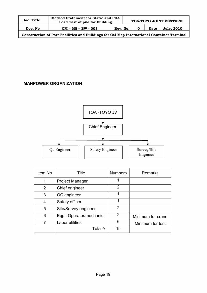
MANPOWER ORGANIZATION
TOA -TOYO JV
Chief Engineer
Page 19
Item No Title Numbers Remarks
1 Project Manager 1
2 Chief engineer 2
3 QC engineer 1
4 Safety officer 1
5 Site/Survey engineer 2
6 Eqpt. Operator/mechanic 2 Minimum for crane
7 Labor utilities 6 Minimum for testTotal→ 15
Safety Engineer Survey/Site Engineer
Qc Engineer