STARLight PDR 3 Oct ‘01I.1 Miller STARLight Control Module Design Ryan Miller STARLight Electrical...
17
TARLight PDR 3 Oct ‘01 I.1 Miller STARLight STARLight Control Module Design Ryan Miller STARLight Electrical Engineer (734) 763-5373 [email protected]
-
date post
19-Dec-2015 -
Category
Documents
-
view
220 -
download
0
Transcript of STARLight PDR 3 Oct ‘01I.1 Miller STARLight Control Module Design Ryan Miller STARLight Electrical...

STARLight PDR 3 Oct ‘01 I.1 Miller
STARLightSTARLight
Control Module Design
Ryan Miller
STARLight Electrical Engineer
(734) 763-5373
STARLight PDR 3 Oct ‘01 I.2 Miller
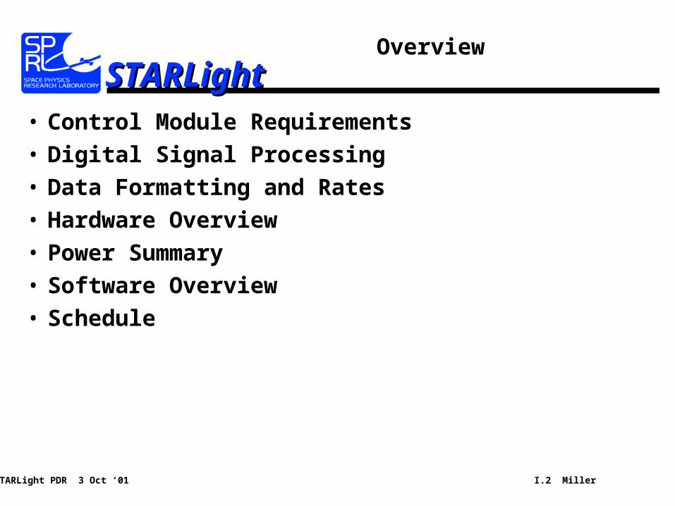
STARLightSTARLightOverview
• Control Module Requirements
• Digital Signal Processing
• Data Formatting and Rates
• Hardware Overview
• Power Summary
• Software Overview
• Schedule
STARLight PDR 3 Oct ‘01 I.3 Miller
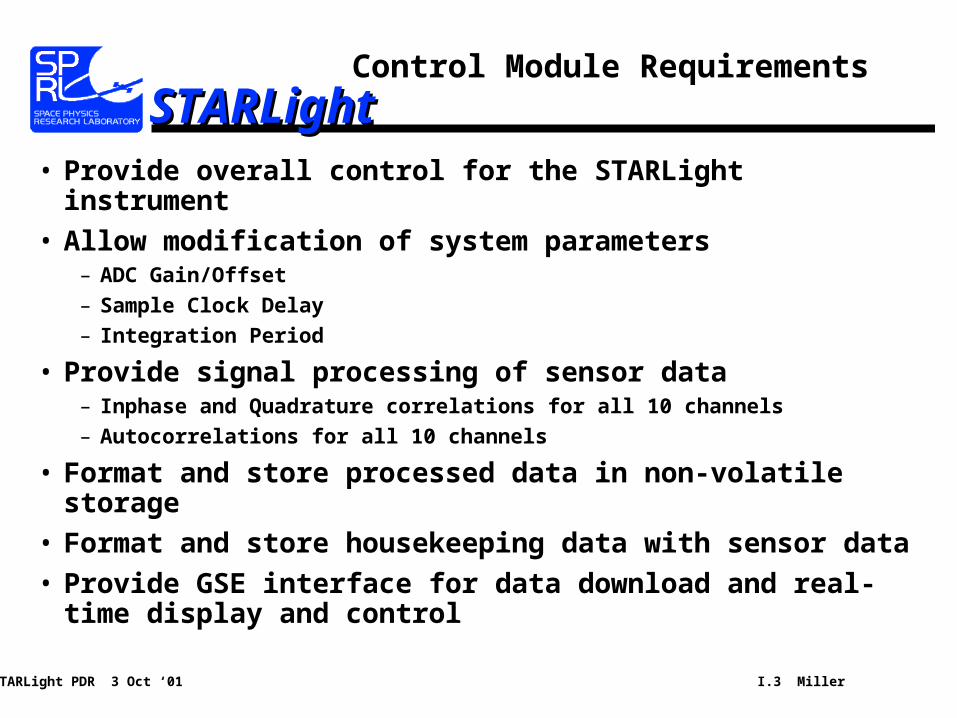
STARLightSTARLightControl Module Requirements
• Provide overall control for the STARLight instrument
• Allow modification of system parameters– ADC Gain/Offset
– Sample Clock Delay
– Integration Period
• Provide signal processing of sensor data– Inphase and Quadrature correlations for all 10 channels
– Autocorrelations for all 10 channels
• Format and store processed data in non-volatile storage
• Format and store housekeeping data with sensor data
• Provide GSE interface for data download and real-time display and control
STARLight PDR 3 Oct ‘01 I.4 Miller
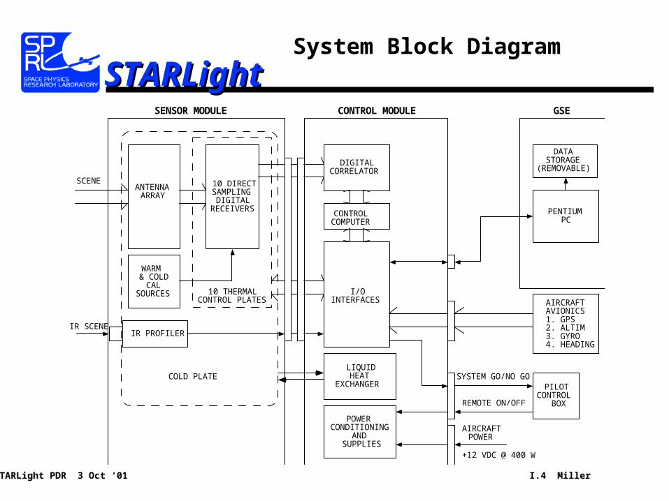
STARLightSTARLightSystem Block Diagram
DIGITALCORRELATOR
CONTROLCOMPUTER
PENTIUMPC
POWERCONDITIONING
ANDSUPPLIES
+12 VDC @ 400 W
AIRCRAFTAVIONICS1. GPS2. ALTIM3. GYRO4. HEADING
DATASTORAGE
(REMOVABLE)
SENSOR MODULE CONTROL MODULE
REMOTE ON/OFF
SCENE
IR PROFILER
AIRCRAFTPOWER
I/OINTERFACES
PILOTCONTROL
BOX
SYSTEM GO/NO GO
GSE
WARM& COLD
CALSOURCES
IR SCENE
ANTENNAARRAY
LIQUIDHEAT
EXCHANGER
10 DIRECTSAMPLING
DIGITALRECEIVERS
10 THERMALCONTROL PLATES
COLD PLATE
STARLight PDR 3 Oct ‘01 I.5 Miller
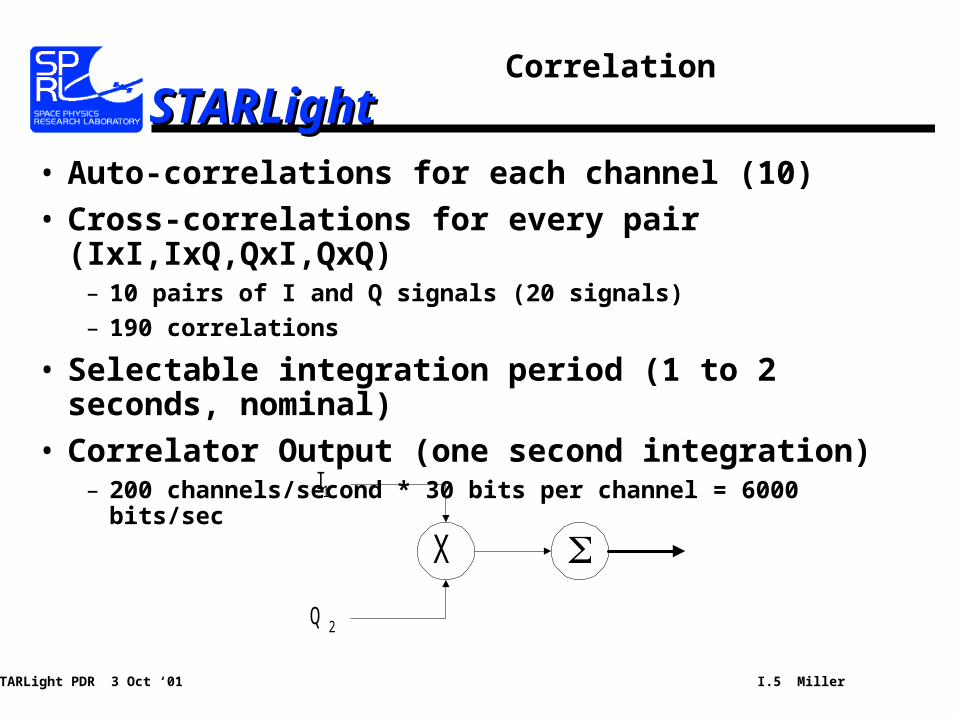
STARLightSTARLightCorrelation
• Auto-correlations for each channel (10)
• Cross-correlations for every pair (IxI,IxQ,QxI,QxQ)– 10 pairs of I and Q signals (20 signals)
– 190 correlations
• Selectable integration period (1 to 2 seconds, nominal)
• Correlator Output (one second integration)– 200 channels/second * 30 bits per channel = 6000 bits/sec
X
I1
Q 2
STARLight PDR 3 Oct ‘01 I.6 Miller
STARLightSTARLightData Storage Requirements
• Total Data Rate = 11,000 bits/sec– Sensor: 6000 bps– Housekeeping: 3000 bps– Other: 2000 bps
• Mission Time is approximately 3 hours
• Total on-board storage needed:– 11000 bits/sec * 3 hours * 3600 sec/hour = 15 Megabytes

STARLight PDR 3 Oct ‘01 I.7 Miller
STARLightSTARLightControl Module Electronics Block
Diagram
Correlator Board
Control Computer
Control ModuleData Acquisition
Terminal BoardThermocouple
InterfaceFrom IR Profiler
Sensor Status andControl Interface
High-Speed SensorData Interface
Power SupplySensorPower
Distribution
100 BaseT GSEInterface
Aircraft PowerInput
Ground AuxilliaryPower Input
Serial RS-422Interface from
Avionics
PSMonitors
Pilot StatusInterface
STARLight PDR 3 Oct ‘01 I.8 Miller
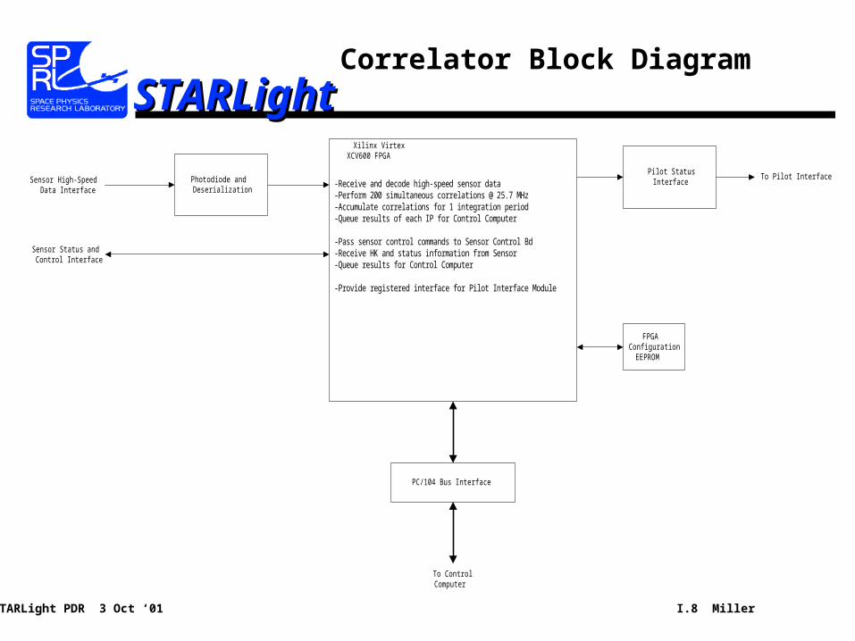
STARLightSTARLightCorrelator Block Diagram
Sensor Status andControl Interface
Photodiode andDeserialization
Sensor High-SpeedData Interface
PC/104 Bus Interface
To ControlComputer
Pilot StatusInterface
To Pilot Interface
Xilinx VirtexXCV600 FPGA
FPGAConfiguration
EEPROM
-Receive and decode high-speed sensor data-Perform 200 simultaneous correlations @ 25.7 MHz-Accumulate correlations for 1 integration period-Queue results of each IP for Control Computer
-Pass sensor control commands to Sensor Control Bd-Receive HK and status information from Sensor-Queue results for Control Computer
-Provide registered interface for Pilot Interface Module
STARLight PDR 3 Oct ‘01 I.9 Miller
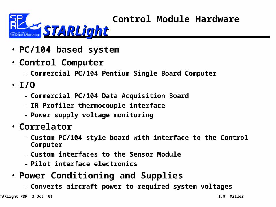
STARLightSTARLightControl Module Hardware
• PC/104 based system
• Control Computer– Commercial PC/104 Pentium Single Board Computer
• I/O– Commercial PC/104 Data Acquisition Board
– IR Profiler thermocouple interface
– Power supply voltage monitoring
• Correlator– Custom PC/104 style board with interface to the Control Computer
– Custom interfaces to the Sensor Module
– Pilot interface electronics
• Power Conditioning and Supplies– Converts aircraft power to required system voltages
STARLight PDR 3 Oct ‘01 I.10 Miller
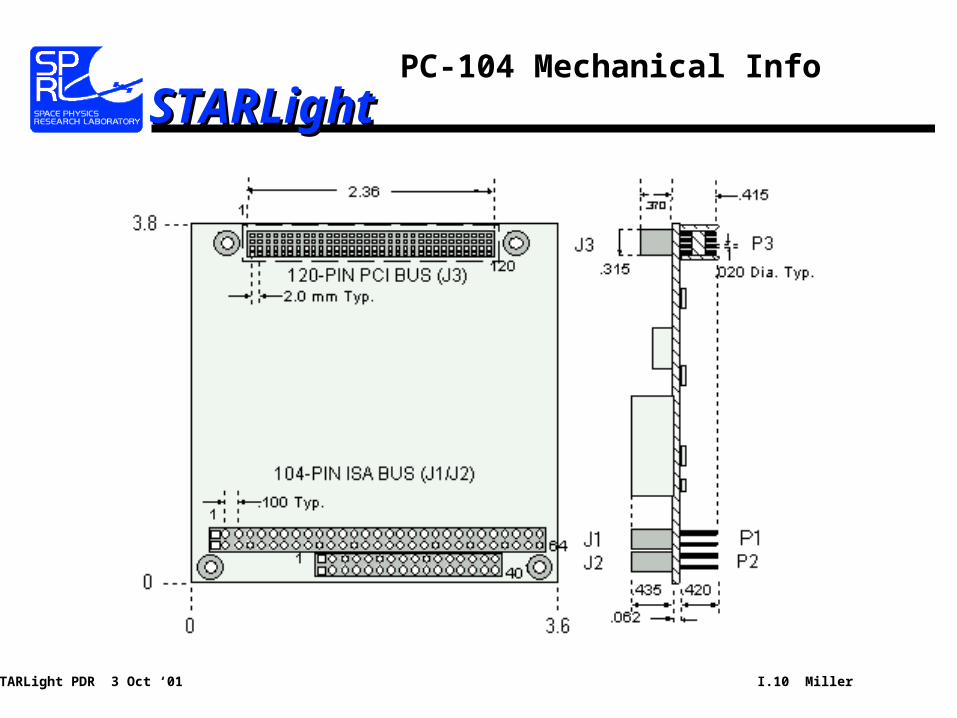
STARLightSTARLightPC-104 Mechanical Info
STARLight PDR 3 Oct ‘01 I.11 Miller
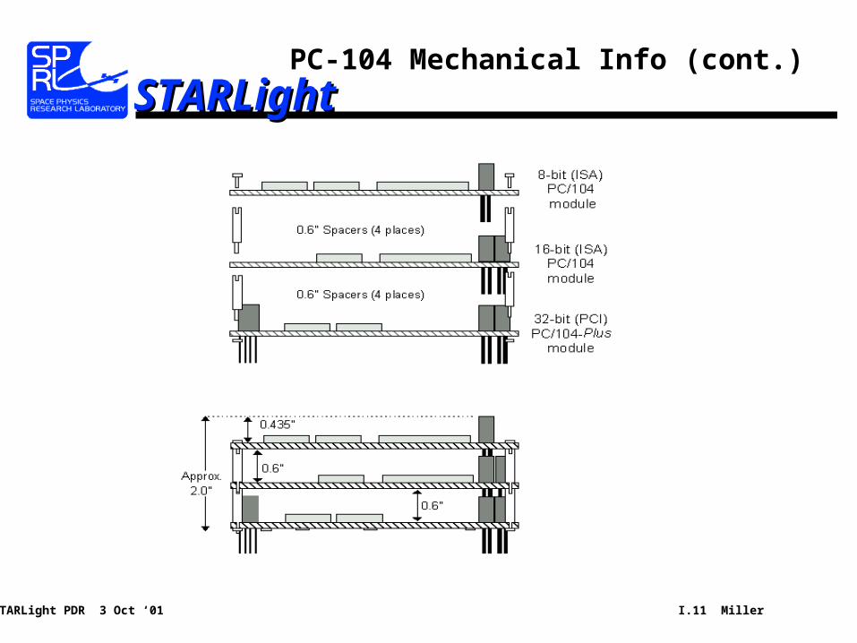
STARLightSTARLightPC-104 Mechanical Info (cont.)
STARLight PDR 3 Oct ‘01 I.12 Miller
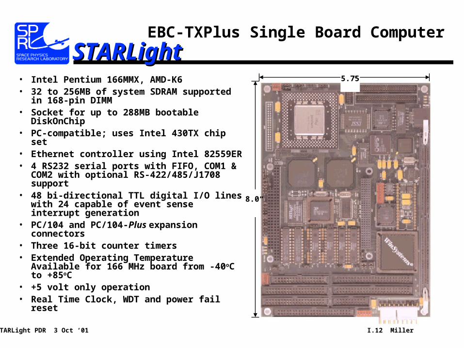
STARLightSTARLightEBC-TXPlus Single Board Computer
8.0”
5.75”• Intel Pentium 166MMX, AMD-K6• 32 to 256MB of system SDRAM supported
in 168-pin DIMM• Socket for up to 288MB bootable
DiskOnChip• PC-compatible; uses Intel 430TX chip set• Ethernet controller using Intel 82559ER• 4 RS232 serial ports with FIFO, COM1 &
COM2 with optional RS-422/485/J1708 support
• 48 bi-directional TTL digital I/O lines with 24 capable of event sense interrupt generation
• PC/104 and PC/104-Plus expansion connectors
• Three 16-bit counter timers• Extended Operating Temperature
Available for 166 MHz board from -40oC to +85oC
• +5 volt only operation• Real Time Clock, WDT and power fail reset
STARLight PDR 3 Oct ‘01 I.13 Miller
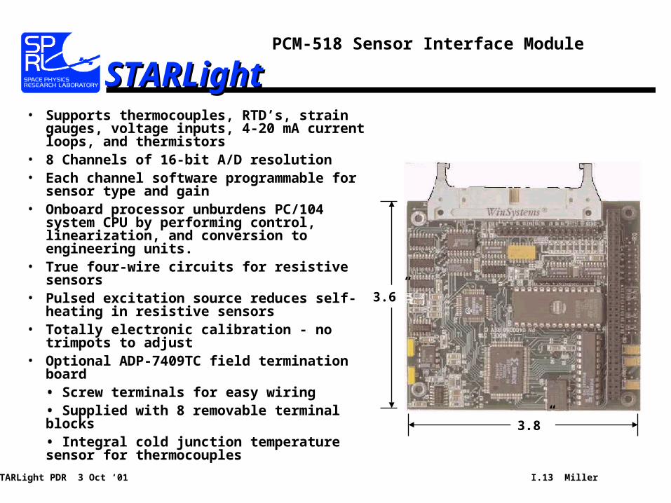
STARLightSTARLightPCM-518 Sensor Interface Module
3.6”
3.8”
• Supports thermocouples, RTD’s, strain gauges, voltage inputs, 4-20 mA current loops, and thermistors
• 8 Channels of 16-bit A/D resolution• Each channel software programmable for
sensor type and gain• Onboard processor unburdens PC/104
system CPU by performing control, linearization, and conversion to engineering units.
• True four-wire circuits for resistive sensors• Pulsed excitation source reduces self-heating
in resistive sensors• Totally electronic calibration - no trimpots to
adjust• Optional ADP-7409TC field termination board
• Screw terminals for easy wiring• Supplied with 8 removable terminal blocks• Integral cold junction temperature sensor for thermocouples
STARLight PDR 3 Oct ‘01 I.14 Miller
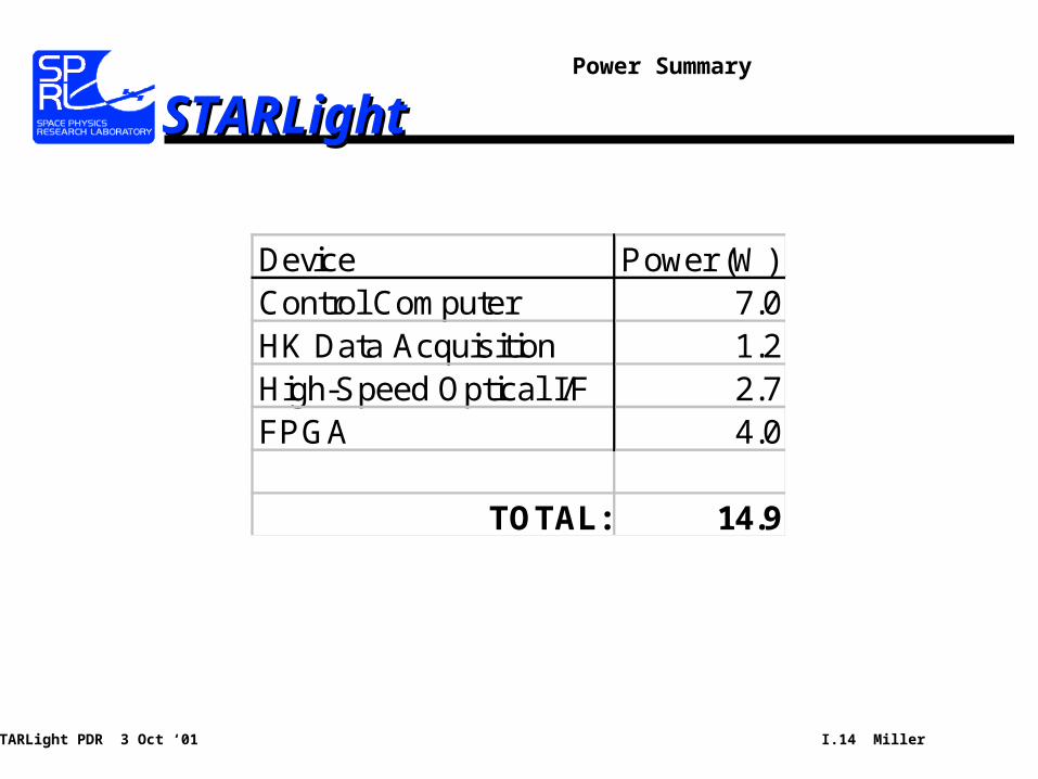
STARLightSTARLightPower Summary
Device Power (W)Control Computer 7.0HK Data Acquisition 1.2High-Speed Optical I/F 2.7FPGA 4.0
TOTAL: 14.9
STARLight PDR 3 Oct ‘01 I.15 Miller
STARLightSTARLightSoftware Overview
• Developed using QNX – Real-time Operating System– Provides real-time operation, interrupt handling, TCP/IP networking
• Provides overall system control– Sensor parameter setting– Data collection– Data formatting and storage
• Provides thermal system control– PID Loops using sensor temperature measurements, 10 channels
• Provides GSE interface– 100 BaseT TCP/IP– Realtime data transmission– Stored data collection– Interactive control
STARLight PDR 3 Oct ‘01 I.16 Miller
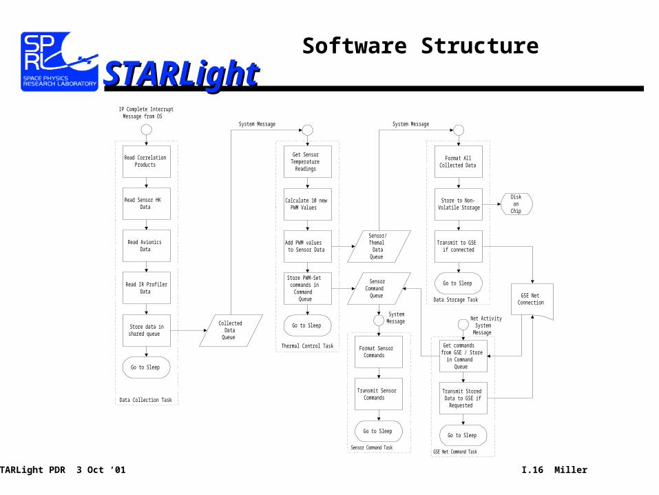
STARLightSTARLightSoftware Structure
Read CorrelationProducts
Read Sensor HKData
CollectedData
Queue
Read AvionicsData
Read IR ProfilerData
Store data inshared queue
Go to Sleep
IP Complete InterruptMessage from OS
Get SensorTemperature
Readings
Calculate 10 newPWM Values
Add PWM valuesto Sensor Data
Go to Sleep
Data Collection Task
Thermal Control Task
SensorCommand
Queue
System Message
Store PWM-Setcommands in
CommandQueue
Sensor/Themal
DataQueue
Format SensorCommands
Transmit SensorCommands
Go to Sleep
SystemMessage
Format AllCollected Data
Store to Non-Volatile Storage
Go to Sleep
Sensor Command Task
System Message
Data Storage Task
Transmit to GSEif connected
Diskon
Chip
Get commandsfrom GSE / Store
in CommandQueue
Transmit StoredData to GSE if
Requested
Go to Sleep
Net ActivitySystem
Message
GSE Net Command Task
GSE NetConnection
STARLight PDR 3 Oct ‘01 I.17 Miller
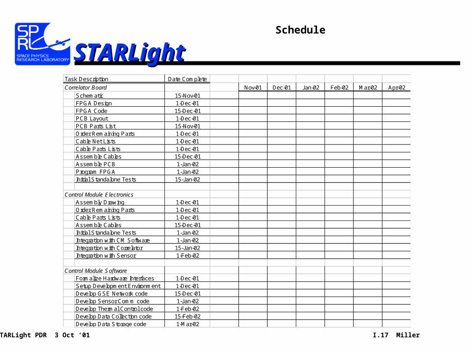
STARLightSTARLightSchedule
Task Description Date Complete
Correlator Board Nov-01 Dec-01 Jan-02 Feb-02 Mar-02 Apr-02Schematic 15-Nov-01FPGA Design 1-Dec-01FPGA Code 15-Dec-01PCB Layout 1-Dec-01PCB Parts List 15-Nov-01Order Remaining Parts 1-Dec-01Cable Net Lists 1-Dec-01Cable Parts Lists 1-Dec-01Assemble Cables 15-Dec-01Assemble PCB 1-Jan-02Program FPGA 1-Jan-02Initial Standalone Tests 15-Jan-02
Control Module ElectronicsAssembly Drawing 1-Dec-01Order Remaining Parts 1-Dec-01Cable Parts Lists 1-Dec-01Assemble Cables 15-Dec-01Initial Standalone Tests 1-Jan-02Integration with CM Software 1-Jan-02Integration with Correlator 15-Jan-02Integration with Sensor 1-Feb-02
Control Module SoftwareFormalize Hardware Interfaces 1-Dec-01Setup Development Environment 1-Dec-01Develop GSE Network code 15-Dec-01Develop Sensor Comm code 1-Jan-02Develop Thermal Control code 1-Feb-02Develop Data Collection code 15-Feb-02Develop Data Storage code 1-Mar-02