goldcoastjazz.org browardcenter.org 954-524-0805 954-462-0222
Starbox
Installation guide
P1
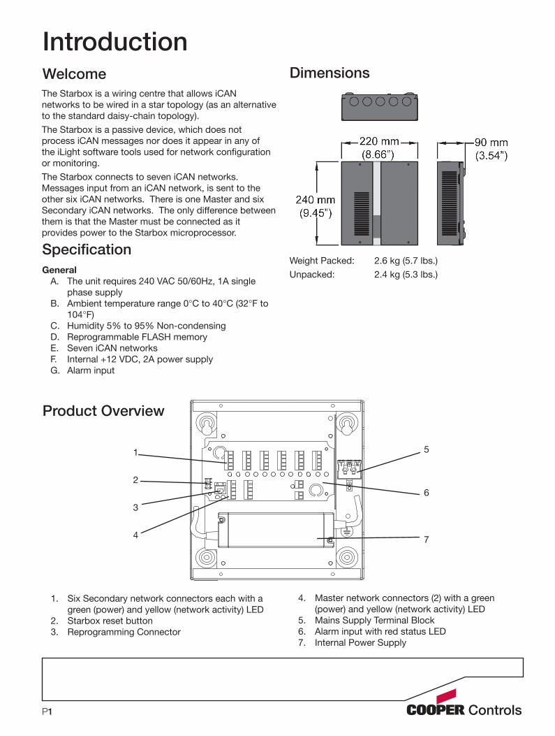
The Starbox is a wiring centre that allows iCAN networks to be wired in a star topology (as an alternative to the standard daisy-chain topology).The Starbox is a passive device, which does not process iCAN messages nor does it appear in any of the iLight software tools used for network configuration or monitoring. The Starbox connects to seven iCAN networks. Messages input from an iCAN network, is sent to the other six iCAN networks. There is one Master and six Secondary iCAN networks. The only difference between them is that the Master must be connected as it provides power to the Starbox microprocessor.
Dimensions
SpecificationGeneral
A. The unit requires 240 VAC 50/60Hz, 1A single phase supply
B. Ambient temperature range 0°C to 40°C (32°F to 104°F)
C. Humidity 5% to 95% Non-condensingD. Reprogrammable FLASH memoryE. Seven iCAN networksF. Internal +12 VDC, 2A power supplyG. Alarm input
IntroductionWelcome
Weight Packed: 2.6 kg (5.7 lbs.)Unpacked: 2.4 kg (5.3 lbs.)
Product Overview
5
6
7
1
2
3
4
1. Six Secondary network connectors each with a green (power) and yellow (network activity) LED
2. Starbox reset button3. Reprogramming Connector
4. Master network connectors (2) with a green (power) and yellow (network activity) LED
5. Mains Supply Terminal Block6. Alarm input with red status LED7. Internal Power Supply
P2
Please read this first
By following the steps listed below and elsewhere within this guide, you can ensure safe installation and operation of this unit.
• The installation must comply with the appropriate electrical codes and regulations in force in your area.
• Ensure that all wiring used conforms fully to local specifications and is sufficiently rated for the installation.
• All new wiring must be fully verified before applying power.
• Ensure that high voltage and low voltage wiring remains separate.
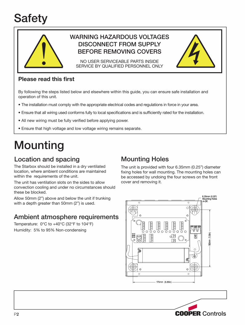
Safety
MountingLocation and spacingThe Starbox should be installed in a dry ventilated location, where ambient conditions are maintained within the requirements of the unit.The unit has ventilation slots on the sides to allow convection cooling and under no circumstances should these be blocked.Allow 50mm (2”) above and below the unit if trunking with a depth greater than 50mm (2”) is used.
Ambient atmosphere requirementsTemperature: 0°C to +40°C (32°F to 104°F)Humidity: 5% to 95% Non-condensing
The unit is provided with four 6.35mm (0.25”) diameter fixing holes for wall mounting. The mounting holes can be accessed by undoing the four screws on the front cover and removing it.
Mounting Holes
175mm (6.89in)
180m
m(7.
09in)
6.35mm (0.25")Mounting Holes4-Off.
!WARNING HAZARDOUS VOLTAGES
DISCONNECT FROM SUPPLY BEFORE REMOVING COVERS
NO USER SERVICEABLE PARTS INSIDESERVICE BY QUALIFIED PERSONNEL ONLY

P3
Connecting the SupplyThis unit requires a 100-240V (50-60 Hz) single phase supply (live and neutral) with 1.0 A capability.A screwless terminal block is used to connect the mains input to the internal power supply
Supply Wiring
Wire Gauge for Supply Terminals
Mains input cable size for live, neutral, and earth is from 1.00mm2 to 2.5mm2.
The live, neutral, and earth mains input are pushed into the terminals on the input side of the connector. Each of these wires can only be released by depressing the corresponding tab.
Neutral
EarthLive
Control Wiring
There is no electrical isolation between iCAN • networks.
The shield on each connector is connected to • chassis ground via a 470K ohm resistor.
The Master network must be used because the Starbox is powered by the 12V of the Master network. The green LED (LD1) indicates that the Master network and the Starbox is powered. As shipped from the factory, the Master network is powered by the internal power supply.Two 5 way connector blocks (CON1 and CON2) are provided for the connection of the iCAN network cable to the Master terminals.The Master iCAN network is also connected to an RJ12 (CON9) socket in parallel with CON1 and CON2. The yellow LED (ACT) next to the master network connectors indicates Master iCAN network activity.
iCAN Network
Master iCAN Network
All iCAN Messages received by the Starbox from • any network are output to the other six iCAN networks.
One 5 way connector is provided for each of the six Secondary iCAN Networks (1-6, CON3-8 respectively). When power (+12V and 0V) is connected to each of the Secondary iCAN networks the green LED (PWR) is turned ON. The yellow LED (ACT) indicates network activity on that Secondary iCAN network.
Secondary iCAN Network
Each of the secondary green power LEDs must be connected to +12V and 0V. This can be achieved by the following options:
Connect them to the master connector via wire • jumpersConnect them to an external power supply.• Connect them to an external iCANet device.•

P4
iCAN Network WiringThe following cable strategies may be used for wiring the iCAN network. It is not recommended to mix cable types in a single installation.Use Belden cable to maximise network runs up to 1000m without a bridge/repeater.
Use CAT5 FTP for economy and wide availability, but there are tighter limitations on the network run without a bridge/repeater.
Cable type: Belden 1502R or 1502PMaximum cable length: 1000m (3275 ft.) Devices per segment: 100 (without bridge or repeater)
Cable type: CAT 5 FTP Maximum cable length: 305m (1000 ft.) Devices per segment: 100 (without bridge or repeater)
iCAN devices are ‘daisy-chained’ on the network. Spurs from the network are not permitted and will result in communication problems. Devices on an iCAN network can be wired in any order. Termination is required at both ends of the network.
Network Termination
The Starbox is provided with a termination resistor fitted to each iCAN network. For each iCAN network that terminates in the Starbox, keep the 120 ohm resistor connected across CAN-H and CAN-L. For each iCAN network that does not terminate in the Starbox, remove the 120 ohm resistor from that connector and store it in the bottom of the Starbox for future use.
Alarm InputConnector CON11 (AL and 0V) provide an Alarm in-put to the Starbox. The Starbox outputs an Alarm On message to all connected iCAN networks when AL is shorted to OV. The Starbox outputs an Alarm Off message to all connected iCAN networks when the short between AL and 0V is cleared.
The Starbox must be energized from the mains for it to operate.The Master green LED indicates that the unit is powered correctly.A red flashing LED indicates that the unit is operating normally.When the red LED is ON, it indicates that there Alarm inputs are close together.Intermittent flashing yellow LEDs indicate that iCAN messages have been output on the corresponding network.The iCANet cables carry low voltage signals and mis-connection of these cables could result in damage to the Starbox and devices connected on the network.
Commissioning
Operation
Connect an iCANet control panel, whose buttons have been programmed with iCAN messages, to the master network and terminate appropriately.Connect a PC node to secondary 1 network and run iCANsoft monitor.Press a control panel button and check that the message sent by the control panel is received by iCANsoft monitor.If the message is not received, check the cabling and termination resistors.Repeat the above process for all secondary networks.
Verify iCAN Networks

Document 73-954-00 IM8896 Iss.01
iLight Cooper Controls Limited Unit 4, Enterprise Centre Penshurst, Tonbridge Kent, TN11 8BGTel: +44 (0)1892 870072 Fax: +44 (0)1892 870074www.iLight.co.uk
North America Headquarters
203 Cooper Circle
Peachtree City, GA 30269
P: 800-553-3879
F: 800-954-7016
www.coopercontrol.com
International Headquarters
20 Greenhill Crescent
Watford Business Park
Watford, Herts, WD18 8XG. UK
P: +44 (0)1923 495495
F: +44 (0)1923 228796
www.coopercontrol.com
All products manufactured by Cooper Controls and identified with the iLight brand are warranted to be free from defects in material and workmanship and shall conform to and perform in accordance with Seller’s written specifications.
For detailed warranty information, visit our website at www.coopercontrol.com
This warranty will be limited to the repair or replacement, at Seller’s discretion, of any such goods found to be defective, upon their authorized return to Seller. This limited warranty does not apply if the goods have been damaged by acci-dent, abuse, misuse, modification or misapplication, by damage during shipment or by improper service.
There are no warranties, which extend beyond the hereinabove-limited warranty, INCLUDING, BUT NOT LIMITED TO, THE IMPLIED WARRANTY OF MERCHANTABILITY AND THE IMPLIED WARRANTY OF FITNESS.
No employee, agent, dealer, or other person is authorized to give any warranties on behalf of the Seller or to assume for the Seller any other liability in connection with any of its goods except in writing and signed by the Seller. The Seller makes no representation that the goods comply with any present or future federal, state or local regulation or ordinance. Compliance is the Buyer’s responsibility.
The use of the Seller’s goods should be in accordance with the provision of the National Electrical Code, UL and/or other industry or military standards that are pertinent to the particular end use. Installation or use not in accordance with these codes and standards could be hazardous.


![Our First Tech Product Launch on Product Hunt: STARBOX Plugin [case study]](https://static.fdocuments.us/doc/165x107/58f2fdd61a28ab2b638b4585/our-first-tech-product-launch-on-product-hunt-starbox-plugin-case-study.jpg)