STANDBY BATTERY RACK ASSEMBLY INSTRUCTIONS · in location using supplied 3/8” bolt, washer,...
8
STANDBY BATTERY RACK ASSEMBLY INSTRUCTIONS APPLIES TO ALL RDC SERIES RACKS (READ ALL INSTRUCTIONS PRIOR TO INSTALLATION) Standard and Earthquake-Protected (EP) Racks: Earthquake-protected racks are similar to standard racks, with the exception of additional frame bracing, battery restraints, and cell spacer elements. The battery rack frames are common for Standard, EP1 and EP2 series for the one-tier, two-tier, three-tier and two-step racks with the exception of the three-tier EP2 rack. The frame for the three-tier EP2 rack is unique. RDC-EP racks are certified to the International Building Code, 2009 edition. Configuration: Racks are available in single or multiple tier/step configurations as shown in Figure 2. Rack components are supplied loose and must be assembled and secured on-site in accordance with these C&D assembly instructions, the drawings included with the rack shipment, and applicable codes. Rack Location: Locate racks in a clean, cool, dry place so the batteries are not affected by sources of radiant heat, such as sunshine, heating units, radiators, steam pipes, etc. Variations of more than 5 degrees Fahrenheit (3º C) between cells may cause the battery to become electrically unbalanced. Top rows of batteries in multiple-tier configurations tend to operate at slightly higher temperature than those on lower tiers. Always provide adequate ceiling clearance for ventilation and maintenance. Anchoring: To provide stability and safety, racks must be securely anchored to the floor. Anchor bolts are to be installed per contractor specifications and in accordance with applicable codes. Do not attach rack to walls without consulting the appropriate structural engineer. Mounting holes are provided in the base of each frame. All frames must be secured to floor using all anchor bolt hole locations. • Do not install batteries until the rack has been properly installed, with all bolts tightened to specified torque and frames anchored to the floor. • Do not use oil or grease as a lubricant for cell installation. Lubrication is usually not required due to the low friction interface of the insulating covers. If necessary, a small amount of water, unscented talcum or Dow Corning III can be applied to the rail covers to reduce friction. CAUTION: Grounding: Rack grounding provisions are integrated into the base of each frame. Two through holes are located at the center of the frame’s bottom cross member and may be used to secure a standard NEMA lug. These holes are 0.44” in diameter and 1.0” between centers. The surfaces surrounding the holes have been masked and are free of powder coat to allow electrical contact. Frame to frame grounding integrity is accomplished via the lower support rail, attached to each frame with internal/external “star” washers. Two Tier Standard Rack Two Tier EP Rack Figure 1. Standard Vs. EP Rack Figure 2. Typical Rack Configurations RS02098 These instructions detail the proper procedure for installing C&D Standard and EP (Earthquake Protected) battery racks. The following describes how to locate, assemble, and load open-frame battery racks for C&D battery mounting applications. Proper attention to these instructions will help ensure safe, trouble-free performance. TYPICAL RACK GROUNDING PROVISION 2-Step 1 Tier 2-Tier 3-Tier Std & EP1 3-Tier EP2 RS02098/0114/CD www.cdtechno.com
Transcript of STANDBY BATTERY RACK ASSEMBLY INSTRUCTIONS · in location using supplied 3/8” bolt, washer,...

STANDBY BATTERY RACK ASSEMBLY INSTRUCTIONSAPPLIES TO ALL RDC SERIES RACKS (READ ALL INSTRUCTIONS PRIOR TO INSTALLATION)
Standard and Earthquake-Protected (EP) Racks:Earthquake-protected racks are similar to standard racks, with the exception of additional frame bracing, battery restraints, and cell spacer elements. The battery rack frames are common for Standard, EP1 and EP2 series for the one-tier, two-tier, three-tier and two-step racks with the exception of the three-tier EP2 rack. The frame for the three-tier EP2 rack is unique. RDC-EP racks are certified to the International Building Code, 2009 edition.
Configuration:Racks are available in single or multiple tier/step configurations as shown in Figure 2. Rack components are supplied loose and must be assembled and secured on-site in accordance with these C&D assembly instructions, the drawings included with the rack shipment, and applicable codes.
Rack Location:Locate racks in a clean, cool, dry place so the batteries are not affected by sources of radiant heat, such as sunshine, heating units, radiators, steam pipes, etc. Variations of more than 5 degrees Fahrenheit (3º C) between cells may cause the battery to become electrically unbalanced. Top rows of batteries in multiple-tier configurations tend to operate at slightly higher temperature than those on lower tiers. Always provide adequate ceiling clearance for ventilation and maintenance.
Anchoring:To provide stability and safety, racks must be securely anchored to the floor. Anchor bolts are to be installed per contractor specifications and in accordance with applicable codes. Do not attach rack to walls without consulting the appropriate structural engineer. Mounting holes are provided in the base of each frame. All frames must be secured to floor using all anchor bolt hole locations.
• Do not install batteries until the rack has been properly installed, with all bolts tightened to specified torque and frames anchored to the floor.
• Do not use oil or grease as a lubricant for cell installation. Lubrication is usually not required due to the low friction interface of the insulating covers. If necessary, a small amount of water, unscented talcum or Dow Corning III can be applied to the rail covers to reduce friction.
CAUTION:
Grounding:Rack grounding provisions are integrated into the base of each frame. Two through holes are located at the center of the frame’s bottom cross member and may be used to secure a standard NEMA lug. These holes are 0.44” in diameter and 1.0” between centers. The surfaces surrounding the holes have been masked and are free of powder coat to allow electrical contact. Frame to frame grounding integrity is accomplished via the lower support rail, attached to each frame with internal/external “star” washers.
Two Tier Standard Rack Two Tier EP Rack
Figure 1. Standard Vs. EP Rack
Figure 2. Typical Rack Configurations
RS02098
These instructions detail the proper procedure for installing C&D Standard and EP (Earthquake Protected) battery racks. The following describes how to locate, assemble, and load open-frame battery racks for C&D battery mounting applications. Proper attention to these instructions will help ensure safe, trouble-free performance. Standard vs. EP2 Rack
Two Tier Standard Rack Two Tier EP2 Rack
TYPICAL RACK GROUNDINGPROVISION
2-Step 1 Tier 2-Tier 3-TierStd & EP1
3-TierEP2
RS02098/0114/CD www.cdtechno.com

ASSEMBLY INSTRUCTIONS FOR RDC STANDARD AND EP RACKS1. Material Verification: Battery racks are shipped
unassembled with a complete set of related drawings and documentation. Check received parts and quantities against the rack’s bill of materials on provided drawings and/or packing list. Do not assemble rack if parts are missing or quantities are incomplete.
2. Required Tools: Torque wrench (0 to 65 ft.-lb.) with 9/16” and 3/4” hex socket. Adjustable wrench or 9/16” and 3/4” box wrenches, tape measure, square and leveling device. Note: Consult manufacturer’s instructions for tools required to install floor mounting hardware.
3. Location of Rack Assembly: When determining rack location and floor anchoring pattern, use applicable drawings provided with rack shipment. The optional arrangement drawing, if ordered, should also be reviewed for rack and battery cell placement. Consider boundaries and aisle clearances when locating the general position of the rack.
Locate floor mounting locations using provided drawings. See Figure 3. Note: Floor mounting hardware must be determined in accordance with applicable building codes. C&D does not provide floor mounting hardware. SEE PAGE 7 & 8 FOR LOCATION OF MULTI-RACK ARRANGEMENTS.
4. Initial Assembly: Anchor bolt washers (P/N RD05084 or RD05100 for three tier racks) are supplied with the EP racks. Each washer should be placed against the rack frame (see Detail A). Place frames over the installed floor mounting hardware, place the anchor bolt washers, and finger tighten floor mounting hardware. All frames must face the same direction. Install rear cross braces finger tight. See Figure 4 and Detail B. Do not install front cross braces at this time (if required). Note: Cross bracing is used in all rear bays for EP1 racks (except for 2 step racks) and in all front and rear bays for EP2 racks. Reference the rack assembly drawings included in shipment for further details of the cross bracing pattern and location for your specific rack model.
Anchor BoltWasher
Anchor Bolt Washer Installation
Initial Assembly
Rear Cross Brace(s)
Frame
Frame and CrossBrace Connection
See Detail B
Floor MountingHardwareSee Detail A
Note FrameOrientation
Frame Upright
Cross Brace
1/2-13 Bolt, LockWasher and Nut
Brace to Frameconnection (Reverse View)
DETAIL A DETAIL B
FIGURE 3 FIGURE 4
RS02098/0114/CD 2 www.cdtechno.com
Rack Assembly Locationand Anchoring Hole Pattern
2.00" Typical Clearance AroundExisting Boundary
As Required AisleClearance

5. Installing Support Rail(s): See Figure 5. Place support rail(s) in location using supplied 3/8” bolt, washer, serrated strut nut and finger tighten (see Detail C). Align support rails with “A” dimension from rack assembly drawing (See Detail D) and install rail covers. Note: An internal/external “star” washer is used in place of the lock washer on the bottom tier or step for grounding connection. Optional third rail should be installed at this time.
For rack lengths greater than 20 ft, the rails come in two sections and are to be joined with a rail splice kit (P/N RE05149 (See Figure 6). The rail lengths have been sized to ensure that the joint occurs near the middle of the span between two frames.
ASSEMBLY INSTRUCTIONS FOR RDC STANDARD AND EP RACKS 6. Leveling: Check that the rack is level and square. Torque down
all bolts. First torque the cross brace bolts to 55-65 ft.-lb. [75-88 N-m], then torque the rail to frame bolts to 15-20 ft.-lbs [20-27 N-m]. Torque anchor bolts to manufacturer’s recommended value.
This concludes the steps required to install a C&D Standard Rack, please proceed to step 8 for cell installation or if you are installing an EP Rack, continue on to step 7.
Rack Label Placement
"A"
"A"See rackassembly drawing
for "A" valuesSupport Rail Location
Support Railand Cover
3/8-16 Hex Bolt
Channel
Serrated Nut
Support Railand Cover
Rail Splice KitAssembled
(P/N RE05149)
Rail Splice Kit
FIGURE 5
DETAIL C
DETAIL D FIGURE 6
Rail covers are supplied in 3’ and 4’ lengths. Rail covers are to be placed end to end over the entire rail length.
RS02098/0114/CD 3 www.cdtechno.com
Support Rail Installation
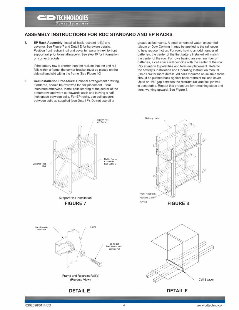
ASSEMBLY INSTRUCTIONS FOR RDC STANDARD AND EP RACKS 7. EP Rack Assembly: Install all back restraint rail(s) and
cover(s). See Figure 7 and Detail E for hardware details. Position front restraint rail and cover temporarily next to front support rail prior to installing cells. See step 10 for information on corner brackets.
If the battery row is shorter than the rack so that the end rail falls within a frame, the corner bracket must be placed on the side rail and slid within the frame (See Figure 10)
8. Cell Installation Procedure: Optional arrangement drawing if ordered, should be reviewed for cell placement. If not instructed otherwise, install cells starting at the center of the bottom row and work out towards each end leaving a half inch space between cells. For EP racks, use cell spacers between cells as supplied (see Detail F). Do not use oil or
grease as lubricants. A small amount of water, unscented talcum or Dow Corning III may be applied to the rail cover to help reduce friction. For rows having an odd number of batteries, the center of the first battery installed will match the center of the row. For rows having an even number of batteries, a cell space will coincide with the center of the row. Pay attention to polarities and terminal placement. Refer to the battery’s Installation and Operating Instruction manual (RS-1476) for more details. All cells mounted on seismic racks should be pushed back against back restraint rail and cover. Up to an 1/8” gap between the restraint rail and cell jar wall is acceptable. Repeat this procedure for remaining steps and tiers, working upward. See Figure 8.
FIGURE 7 FIGURE 8
DETAIL E DETAIL F
Back Restraintand Cover
Frame
3/8-16 Bolt,Lock Washer and
Serrated Nut
Frame and Restraint Rail(s)(Reverse View)
Battery Units
Front Restraint
Rail and Cover
(loose)
RS02098/0114/CD 4 www.cdtechno.com
Support Railand Cover
Rail to FrameConnectionSee Detail COptional Third
Rail
Support Rail Installation
Cell Spacer

ASSEMBLY INSTRUCTIONS FOR RDC STANDARD AND EP RACKS9. Front Restraint Rail (EP only): With the batteries in place,
slide the front side support rail and cover up from its resting location to its mounting location, aligning with rear side restraint rail. Install hardware and torque to 15-20 ft.-lbs. [20-27 N-m] See Figure 9.
10. Final Assembly: Install corner brackets, end restraint rails, and covers. Position end restraint rail against the end battery unit. See Detail G. Note that the corner bracket may be reversed by 180° if required. When the corner bracket
Corner BracketLocation
Corner Bracket placement whenend restraint rails are within the frame
End RestraintRail and Cover
3/8-16 Hex Boltand Lock Washer
Side RestraintRail and Cover
Serrated Nut
Corner BracketAssembled
Side RestraintRail and Cover
Support Railand Cover
End RestraintRail and Cover
End Rail Restraint Rail(s)and Corner Brackets
assembly is reversed, the end restraint rail is attached to the opposite side of the corner bracket. When reversed the corner bracket is able to slide inside the frame uprights (See Detail H).
Install all front cross braces if indicated by rack assembly drawing. Torque to 55-65 ft.-lbs. [75-80 N-m] See Figure 11 for final rack assembly.
FIGURE 9 DETAIL G
FIGURE 10 DETAIL H
Front Restraint
Rails & Cover
Installed
End Rail Restraint and Corner Bracket Reversed
End RestraintRail and Cover
3/8-16 Hex Boltand Lock Washer
Side RestraintRail and Cover
Serrated Nut
Corner BracketAssembled
Side RestraintRail and Cover
Support Railand Cover
End RestraintRail and Cover
End Rail Restraint Rail(s)and Corner Bracket Reversed
RS02098/0114/CD 5 www.cdtechno.com
ASSEMBLY INSTRUCTIONS FOR RDC STANDARD AND EP RACKS
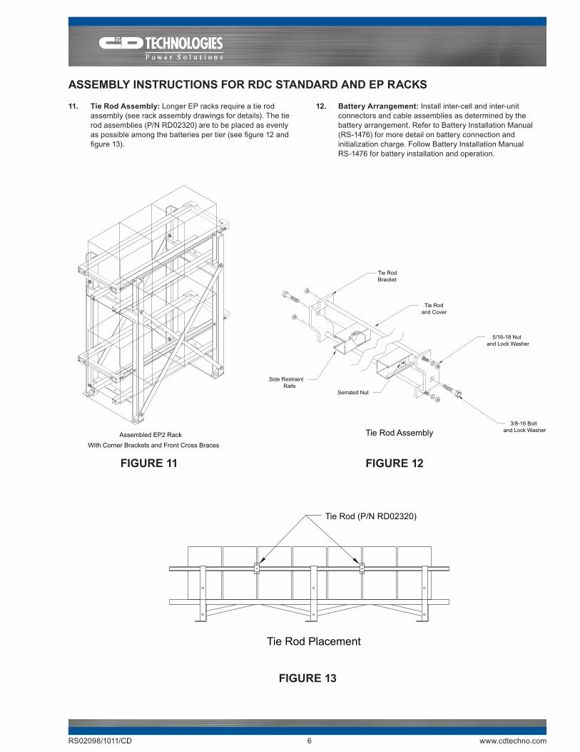
11. Tie Rod Assembly: Longer EP racks require a tie rod assembly (see rack assembly drawings for details). The tie rod assemblies (P/N RD02320) are to be placed as evenly as possible among the batteries per tier (see figure 12 and figure 13).
12. Battery Arrangement: Install inter-cell and inter-unit connectors and cable assemblies as determined by the battery arrangement. Refer to Battery Installation Manual (RS-1476) for more detail on battery connection and initialization charge. Follow Battery Installation Manual RS-1476 for battery installation and operation.
Tie Rodand Cover
Serrated Nut
3/8-16 Boltand Lock Washer
5/16-18 Nutand Lock Washer
Tie RodBracket
Side RestraintRails
Tie Rod Assembly
FIGURE 12FIGURE 11
FIGURE 13
Assembled EP2 RackWith Corner Brackets and Front Cross Braces
Tie Rod (P/N RD02320)
Tie Rod Placement
RS02098/1011/CD 6 www.cdtechno.com

Back to Back Assembly:Where two rows of racks are required, two rack assemblies may be installed back to back.
Frame Location: Locate back to back frames relative to each other as shown in Figure 14, such that the rear cross brace attachment holes align for the two adjoining frames (The frames will be facing opposite directions). All braces must be installed, as described previously, except that a single bolt may be used to connect the front and rear frames and respective cross braces. The ½-13 x 1.50” long bolt supplied with the rack is to be replaced by a ½-13 x 2 ¼” long (supplied with racks).
When placed back to back, there must be enough distance between the frames to allow all of the braces (four total) to be installed. The “X” distance between anchor bolt holes should be as noted in Table 1 (see Figure 15).
Two step standard racks placed back to back do not need to have the frames bolted together. For 2 step EP1 racks a bolt assembly is required (C&D part # REO5253 purchased separately). Contact C&D for more details.
The EP racks have anchor bolt slots with a 1.06” x 0.69” (26.9 mm x 17.5 mm) for One Tier and Two Step rack models and a 1.06” x 0.81” (26.9 mm x 20.6 mm) for Two Tier and Three Tier rack models.
The distance between the anchor bolt locations when the racks are placed back to back is shown in Table 1 and Figure 15.
Note: There may be a de-rating of anchor bolt load ratings due to the proximity of holes. Reference anchor bolt manufacturer’s data for information.
ADDITIONAL INSTRUCTIONS FOR MULTI-RACK ARRANGEMENTS
Table 1
Front of Rack A
Front of Rack B
Back ofRacks A & B
Back to Back Assembly
Anchor BoltCenter Distance
"X"
Anchor Bolt distance (center to center)racks back to back
NOTE:
Anchor selection is determined by the anchor type, the diameter of the anchor, the depth of embedment and anchor spacing. The selection of the anchor bolt must be reviewed by a structural engineer to ensure that the racks will meet the seismic rating for the EP racks.
FIGURE 15FIGURE 14
RDC RackInches mm Inches mm
1 Tier 3.95 100 4.32 1102 Tier 3.88 99 4.08 104
2 Step (Std & EP1) 3.63 92 5.67 1442 Step (EP2) 4.01 102 4.26 1083 Tier (EP1) 4.64 118 3.88 993 Tier (EP2) 4.26 108 4.24 108
"X" DistanceSee Figure 15
Anchor Bolt Distance
RS02098/1011/CD 7 www.cdtechno.com

Any data, descriptions or specifications presented herein are subject to revision by C&D Technologies, Inc. without notice. While such information is believed to be accurate as indicated herein, C&D Technologies, Inc. makes no warranty and hereby disclaims all warranties, express or implied, with regard to the accuracy or completeness of such information. Further, because the product(s) featured herein may be used under conditions beyond its control, C&D Technologies, Inc. hereby disclaims all warranties, either express or implied, concerning the fitness or suitability of such product(s) for any particular use or in any specific application or arising from any course of dealing or usage of trade. The user is solely responsible for determining the suitability of the product(s) featured herein for user’s intended purpose and in user’s specific application.
Copyright 2014 C&D TECHNOLOGIES, INC. Printed in U.S.A. RS02098 0114/CD
1400 Union Meeting RoadP.O. Box 3053 • Blue Bell, PA 19422-0858(215) 619-2700 • Fax (215) 619-7899 • (800) [email protected]
End to End Rack Installation Instructions:Where a continuous rack string is required, two racks may be installed adjacent in length.
Frame Location: End to end rack assemblies are installed as two individual, stand-alone rack assemblies as shown. When installing standard racks, there is no minimum clearance between racks (they can be abutted). When installing EP racks the two racks must be spaced apart so that the minimum distance between the ends of the restraint rails is 5”. If the support rails are fully packed with cells, the end restraint rails may extend beyond the support rails. In such an instance, the 5” clearance dimension should be applied to the corner brackets. See Figure 16.
RACK LABEL:
Place the IBC certification label (one (1) supplied with rack) on a frame upright. Select a frame upright that is readily viewable. See Figure 17.
TOUCH UP PAINT:
Touch up paint (C&D part number RH00289) is available through separate purchase. Contact C&D rep for more details.
ADDITIONAL INSTRUCTIONS FOR MULTI-RACK ARRANGEMENTS
FIGURE 16
End to End Installation
FIGURE 17
Rack Label Placement
End Rail within Support Rails End Rail beyond Support Rails