
Standard Test Methods for Determination of the Soil...
20
Designation: D 6836 – 02 Standard Test Methods for Determination of the Soil Water Chararcteristic Curve for Desorption Using a Hanging Column, Pressure Extractor, Chilled Mirror Hygrometer, and/or Centrifuge 1 This standard is issued under the fixed designation D 6836; the number immediately following the designation indicates the year of original adoption or, in the case of revision, the year of last revision. A number in parentheses indicates the year of last reapproval. A superscript epsilon (e) indicates an editorial change since the last revision or reapproval. 1. Scope 1.1 This test method covers the determination of soil water characteristic curves (SWCCs) for desorption (drying). SWCCs describe the relationship between suction and volu- metric water content, gravimetric water content, or degree of water saturation. SWCCs are also referred to as soil water retention curves, soil water release curves, or capillary pressure curves. 1.2 This standard describes five methods (A-E) for deter- mining the soil water characteristic curve. Method A (hanging column) is suitable for making determinations for suctions in the range of 0 to 80 kPa. Method B (pressure chamber with volumetric measurement) and Method C (pressure chamber with gravimetric measurement) are suitable for suctions in the range of 0 to 1500 kPa. Method D (chilled mirror hygrometer) is suitable for making determinations for suctions in the range of 500 kPa to 100 MPa. Method E (centrifuge method) is suitable for making determinations in the range 0 to 120 kPa. Method A typically is used for coarse soils with little fines that drain readily. Methods B and C typically are used for finer soils which retain water more tightly. Method D is used when suctions near saturation are not required and commonly is employed to define the dry end of the soil water characteristic curve (that is, water contents corresponding to suctions > 1000 kPa). Method E is typically used for coarser soils where an appreciable amount of water can be extracted with suctions up to 120 kPa. The methods may be combined to provide a detailed description of the soil water characteristic curve. In this application, Method A or E is used to define the soil water characteristic curve at lower suctions (0 to 80 kPa for A, 0 to 120 kPa for E) near saturation and to accurately identify the air entry suction, Method B or C is used to define the soil water characteristic curve for intermediate water contents and suc- tions (100 to 1000 kPa), and Method D is used to define the soil water characteristic curves at low water contents and higher suctions (> 1000 kPa) and 1.3 All observed and calculated values shall conform to the guide for significant digits and rounding established in Practice D 6026. The procedures in Practice D 6026 that are used to specify how data are collected, recorded, and calculated are regarded as the industry standard. In addition, they are repre- sentative of the significant digits that should generally be retained. The procedures do not consider material variation, purpose for obtaining the data, special purpose studies, or any considerations for the objectives of the user. Increasing or reducing the significant digits of reported data to be commen- surate with these considerations is common practice. Consid- eration of the significant digits to be used in analysis methods for engineering design is beyond the scope of this standard. 1.4 This standard does not purport to address all of the safety concerns, if any, associated with its use. It is the responsibility of the user of this standard to establish appro- priate safety and health practices and determine the applica- bility of regulatory limitations prior to use. 2. Referenced Documents 2.1 ASTM Standards: D 421 Practice for Dry Preparation of Soil Samples for Particle-Size Analysis and Determination of Soil Contents 2 D 425 Test Method for Centrifuge Moisture Equivalent of Soils 2 D 653 Terminology Relating to Soil, Rock, and Contained Fluids 2 D 698 Test Method for Laboratory Compaction Character- istics of Soil Using Standard Effort [600 kN-mJ/m 3 ] 2 D 854 Test Method for Specific Gravity of Soils 2 D 2216 Method for Laboratory Determination of Water (Moisture) Content of Soil, Rock, and Soil-Aggregate Mixtures 2 D 3740 Practice for Minimum Requirements for Agencies Engaged in the Testing and/or Inspection of Soil and Rock as Used in Engineering Design and Construction 2 D 4753 Practice for Minimum Requirements for Agencies Engaged in the Testing and/or Inspection of Soil and Rock as Used in Engineering Design and Construction 2 1 This test method is under the jurisdiction of ASTM Committee D18 on Soil and Rock and is the direct responsibility of Subcommittee D18.04 on Hydrologic Properties of Soil and Rocks. Current edition approved Nov. 11, 2002. Published February 2003. 2 Annual Book of ASTM Standards, Vol 04.08. 1 Copyright © ASTM International, 100 Barr Harbor Drive, PO Box C700, West Conshohocken, PA 19428-2959, United States.
Transcript of Standard Test Methods for Determination of the Soil...
Designation: D 6836 – 02
Standard Test Methods forDetermination of the Soil Water Chararcteristic Curve forDesorption Using a Hanging Column, Pressure Extractor,Chilled Mirror Hygrometer, and/or Centrifuge 1
This standard is issued under the fixed designation D 6836; the number immediately following the designation indicates the year oforiginal adoption or, in the case of revision, the year of last revision. A number in parentheses indicates the year of last reapproval. Asuperscript epsilon (e) indicates an editorial change since the last revision or reapproval.
1. Scope
1.1 This test method covers the determination of soil watercharacteristic curves (SWCCs) for desorption (drying).SWCCs describe the relationship between suction and volu-metric water content, gravimetric water content, or degree ofwater saturation. SWCCs are also referred to as soil waterretention curves, soil water release curves, or capillary pressurecurves.
1.2 This standard describes five methods (A-E) for deter-mining the soil water characteristic curve. Method A (hangingcolumn) is suitable for making determinations for suctions inthe range of 0 to 80 kPa. Method B (pressure chamber withvolumetric measurement) and Method C (pressure chamberwith gravimetric measurement) are suitable for suctions in therange of 0 to 1500 kPa. Method D (chilled mirror hygrometer)is suitable for making determinations for suctions in the rangeof 500 kPa to 100 MPa. Method E (centrifuge method) issuitable for making determinations in the range 0 to 120 kPa.Method A typically is used for coarse soils with little fines thatdrain readily. Methods B and C typically are used for finer soilswhich retain water more tightly. Method D is used whensuctions near saturation are not required and commonly isemployed to define the dry end of the soil water characteristiccurve (that is, water contents corresponding to suctions > 1000kPa). Method E is typically used for coarser soils where anappreciable amount of water can be extracted with suctions upto 120 kPa. The methods may be combined to provide adetailed description of the soil water characteristic curve. Inthis application, Method A or E is used to define the soil watercharacteristic curve at lower suctions (0 to 80 kPa for A, 0 to120 kPa for E) near saturation and to accurately identify the airentry suction, Method B or C is used to define the soil watercharacteristic curve for intermediate water contents and suc-tions (100 to 1000 kPa), and Method D is used to define the soilwater characteristic curves at low water contents and highersuctions (> 1000 kPa) and
1.3 All observed and calculated values shall conform to theguide for significant digits and rounding established in PracticeD 6026. The procedures in Practice D 6026 that are used tospecify how data are collected, recorded, and calculated areregarded as the industry standard. In addition, they are repre-sentative of the significant digits that should generally beretained. The procedures do not consider material variation,purpose for obtaining the data, special purpose studies, or anyconsiderations for the objectives of the user. Increasing orreducing the significant digits of reported data to be commen-surate with these considerations is common practice. Consid-eration of the significant digits to be used in analysis methodsfor engineering design is beyond the scope of this standard.
1.4 This standard does not purport to address all of thesafety concerns, if any, associated with its use. It is theresponsibility of the user of this standard to establish appro-priate safety and health practices and determine the applica-bility of regulatory limitations prior to use.
2. Referenced Documents
2.1 ASTM Standards:D 421 Practice for Dry Preparation of Soil Samples for
Particle-Size Analysis and Determination of Soil Contents2
D 425 Test Method for Centrifuge Moisture Equivalent ofSoils2
D 653 Terminology Relating to Soil, Rock, and ContainedFluids2
D 698 Test Method for Laboratory Compaction Character-istics of Soil Using Standard Effort [600 kN-mJ/m3]2
D 854 Test Method for Specific Gravity of Soils2
D 2216 Method for Laboratory Determination of Water(Moisture) Content of Soil, Rock, and Soil-AggregateMixtures2
D 3740 Practice for Minimum Requirements for AgenciesEngaged in the Testing and/or Inspection of Soil and Rockas Used in Engineering Design and Construction2
D 4753 Practice for Minimum Requirements for AgenciesEngaged in the Testing and/or Inspection of Soil and Rockas Used in Engineering Design and Construction2
1 This test method is under the jurisdiction of ASTM Committee D18 on Soil andRock and is the direct responsibility of Subcommittee D18.04 on HydrologicProperties of Soil and Rocks.
Current edition approved Nov. 11, 2002. Published February 2003. 2 Annual Book of ASTM Standards, Vol 04.08.
1
Copyright © ASTM International, 100 Barr Harbor Drive, PO Box C700, West Conshohocken, PA 19428-2959, United States.
D 5084 Test Methods for Measurement of Hydraulic Con-ductivity of Porous Materials Using a Flexible WallPermeameter3
D 6026 Practice for Using Significant Digits in Geotechni-cal Data3
2.2 API Standard:API RP 40 Recommended Practice for Core-Analysis Pro-
cedure4
3. Terminology
3.1 For common definitions of other terms in this standardsee Terminology D 653.
3.2 Definitions of Terms Specific to This Standard:3.2.1 air entry pressure—the air pressure required to intro-
duce air into and through the pores of a saturated porous plate.3.2.2 air entry suction,ca—the suction required to intro-
duce air into and through the pores of a saturated porousmaterial.
3.2.3 axis translation—the principle stating that a matricsuctionc can be applied to a soil by controlling the pore gaspressure,ug, and the pore water pressure,uw, so that thedifference between the pore gas pressure and pore waterpressure equals the desired matric suction, that is,c = ug − uw.
3.2.4 gravimetric water content, w—the ratio of the mass ofwater contained in the pore spaces of soil or rock to the massof solid particles.
3.2.5 matric suction,c—the negative gage pressure, rela-tive to an external gas pressure acting on the soil water, thatmust be applied to a solution identical in composition to thesoil water to maintain equilibrium through a porous membraneexisting between the solution and the soil water. Matric suctionis also referred to as matric potential, capillary suction, andcapillary potential. By definition, matric suction is the differ-ence between the pore gas pressure,ug, and the pore waterpressure,uw, that is,c = ug − uw. In most cases the pore gas isair.
3.2.6 osmotic suction,co—the negative gage pressure de-rived from the measurement of the vapor pressure of water inequilibrium with a solution identical in composition with thesoil water, relative to the vapor pressure of water in equilibriumwith free pure water. Osmotic suction is also referred to asosmotic potential.
3.2.7 porous membrane—a porous polymeric membranethat can transmit water and has a air entry pressure exceedingthe highest matric suction to be applied during a test.
3.2.8 porous plate—a plate made of metal, ceramic, or otherporous material that can transmit water and has an air entrypressure exceeding the highest matric suction to be appliedduring a test.
3.2.9 pressure chamber—a vessel used to apply a gaspressure on the specimen and the soil pores to induce aspecified matric suction.
3.2.10 saturated water content—volumetric or gravimetricwater content when the specimen is saturated.
3.2.11 soil water characteristic curve—a graph of suction(matric or total) versus water content (gravimetric or volumet-ric) or saturation. The soil water characteristic curve is alsoreferred to as the soil water retention curve, the soil waterrelease curve, and the capillary pressure curve.
3.2.12 total suction,ct—the negative gage pressure derivedfrom the measurement of the vapor pressure of water inequilibrium with water in the soil pores, relative to the vaporpressure of water in equilibrium with free pure water. Totalsuction is the sum of matric and osmotic suction,ct = c + co.Total suction is also referred to as total potential.
3.2.13 volumetric water content,u—the ratio of the volumeof water contained in the pore spaces of soil or rock to the totalvolume of soil and rock.
3.2.14 water activity, aw—the ratio of vapor pressure ofwater in the soil gas to the saturated vapor pressure at theexisting soil temperature. Water activity is also referred to asthe relative humidity.
4. Summary of Methods
4.1 Methods A-C—Methods A-C yield soil water character-istic curves in terms of matric suction. Various suctions areapplied to the soil and the corresponding water contents aremeasured. Two different procedures are used to apply thesuction. In Method A, the matric suction is applied by reducingthe pore water pressure while maintaining the pore gas pressureat the atmospheric condition. In Methods B and C, the porewater pressure is maintained at atmospheric pressure, and thepore gas pressure is raised to apply the suction via the axistranslation principle.
4.1.1 For all three methods, saturated soil specimens areplaced in contact with a water saturated porous plate ormembrane. The matric suction is applied by one of the twoaforementioned procedures. Application of the matric suctioncauses water to flow from the specimen until the equilibriumwater content corresponding to the applied suction is reached.Equilibrium is established by monitoring when water ceases toflow from the specimen. Several equilibria are established atsuccessive matric suctions to construct a soil water character-istic curve.
4.1.2 The water content corresponding to the applied suc-tion is determined in one of two ways. For Methods A and B,the volume of water expelled is measured using a capillarytube. The water content is then determined based on the knowninitial water content of the specimen and the volume of waterexpelled. For Method C, the water content is measuredgravimetrically by weighing the specimen after removal fromthe apparatus.
4.2 Method D—Method D yields a soil water characteristiccurve in terms of total suction. In contrast to Methods A-C, thewater content of the soil is controlled in Method D, and thecorresponding suctions are measured. Two different ap-proaches are commonly used. In one approach, a set ofspecimens are prepared that are essentially identical, but havedifferent water contents. Water contents are selected that spanthe range of water contents that will be used to define the soilwater characteristic curve. In the other approach, a singlespecimen is used. The specimen is tested, dried to a lower
3 Annual Book of ASTM Standards, Vol 04.09.4 American Petroleum Institute, 2nd Edition, 1998.
D 6836 – 02
2
water content, and then tested again. This process is repeateduntil suctions have been measured at all of the desired watercontents.
4.2.1 In Method D, the water activity of the pore water ismeasured using a chilled mirror hygrometer (also known as achilled mirror psychrometer) and then the total suction iscomputed using the Kelvin equation. In many cases, Method Dis used to determine only that portion of the soil watercharacteristic curve corresponding to higher suctions (typically> 1000 kPa) and lower water contents. Under these conditions,the osmotic component of total suction is generally small, andthe matric and total suctions are comparable. Thus, the datafrom Methods A-C and Method D can be combined to form asingle soil water characteristic curve. An example of this typeof soil water characteristic curve is provided in Section 11.
4.3 Method E—Method E yields a soil water characteristiccurve in terms of matric suction (or capillary pressure). Thespecimen is contained in a support chamber that is subjected toa centrifugal force in a centrifuge. Different matric suctions areapplied by varying the angular velocity of the centrifuge. Waterdisplaced from the soil at a given angular velocity is collectedand measured in a calibrated cylinder at the base of the supportchamber. A soil water characteristic curve is measured bysubjecting the specimen to a series of angular velocities (eachcorresponding to a matric suction) and measuring the volumeof water displaced from the soil at each velocity.
5. Significance and Use
5.1 The soil water characteristic curve (SWCC) is funda-mental to hydrological characterization of unsaturated soils andis required for most analyses of water movement in unsaturatedsoils. The SWCC is also used in characterizing the shearstrength and compressibility of unsaturated soils. The unsatur-ated hydraulic conductivity of soil is often estimated usingproperties of the SWCC and the saturated hydraulic conduc-tivity.
5.2 This method applies only to soils containing two porefluids: a gas and a liquid. The liquid is usually water and thegas is usually air. Other liquids may also be used, but cautionmust be exercised if the liquid being used causes excessiveshrinkage or swelling of the soil matrix.
5.3 A full investigation has not been conducted regardingthe correlation between soil water characteristic curves ob-tained using this method and soil water characteristics curvesof in-place materials. Thus, results obtained from this methodshould be applied to field situations with caution and byqualified personnel.
NOTE 1—The quality of the result produced by this standard depends onthe competence of the personnel performing the test and the suitability ofthe equipment and facilities used. Agencies that meet the criteria ofPractice D 3740 are generally considered capable of competent andobjective testing, sampling, inspection, etc. Users of this standard arecautioned that compliance with Practice D 3740 does not in itself ensurereliable results. Reliable results depend on many factors. Practice D 3740provides a means of evaluating some of these factors.
6. Apparatus
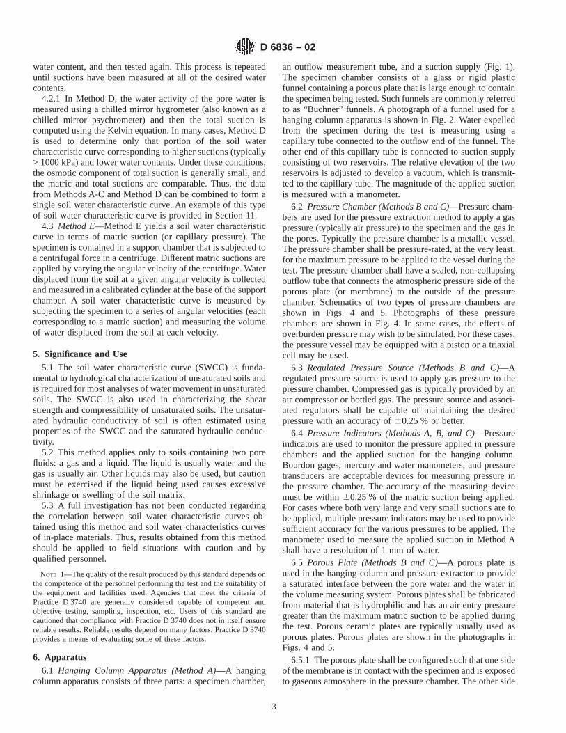
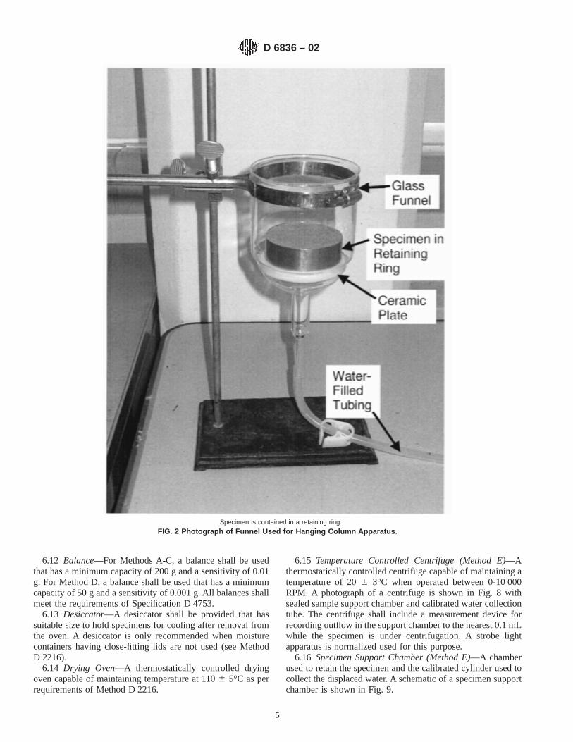
6.1 Hanging Column Apparatus (Method A)—A hangingcolumn apparatus consists of three parts: a specimen chamber,
an outflow measurement tube, and a suction supply (Fig. 1).The specimen chamber consists of a glass or rigid plasticfunnel containing a porous plate that is large enough to containthe specimen being tested. Such funnels are commonly referredto as “Buchner” funnels. A photograph of a funnel used for ahanging column apparatus is shown in Fig. 2. Water expelledfrom the specimen during the test is measuring using acapillary tube connected to the outflow end of the funnel. Theother end of this capillary tube is connected to suction supplyconsisting of two reservoirs. The relative elevation of the tworeservoirs is adjusted to develop a vacuum, which is transmit-ted to the capillary tube. The magnitude of the applied suctionis measured with a manometer.
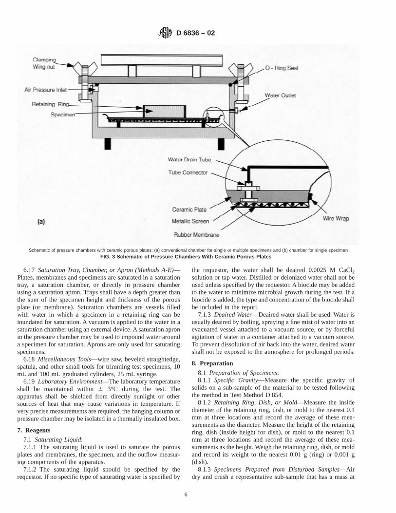
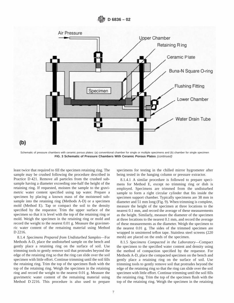
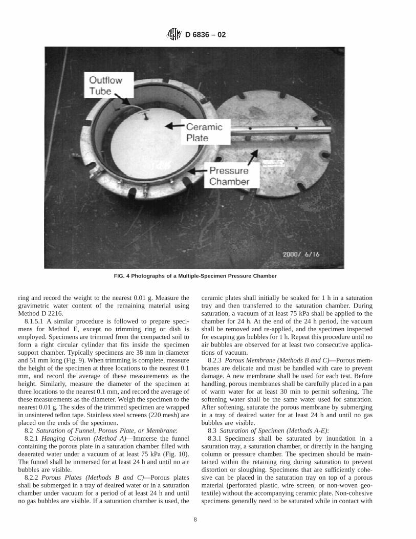
6.2 Pressure Chamber (Methods B and C)—Pressure cham-bers are used for the pressure extraction method to apply a gaspressure (typically air pressure) to the specimen and the gas inthe pores. Typically the pressure chamber is a metallic vessel.The pressure chamber shall be pressure-rated, at the very least,for the maximum pressure to be applied to the vessel during thetest. The pressure chamber shall have a sealed, non-collapsingoutflow tube that connects the atmospheric pressure side of theporous plate (or membrane) to the outside of the pressurechamber. Schematics of two types of pressure chambers areshown in Figs. 4 and 5. Photographs of these pressurechambers are shown in Fig. 4. In some cases, the effects ofoverburden pressure may wish to be simulated. For these cases,the pressure vessel may be equipped with a piston or a triaxialcell may be used.
6.3 Regulated Pressure Source (Methods B and C)—Aregulated pressure source is used to apply gas pressure to thepressure chamber. Compressed gas is typically provided by anair compressor or bottled gas. The pressure source and associ-ated regulators shall be capable of maintaining the desiredpressure with an accuracy of60.25 % or better.
6.4 Pressure Indicators (Methods A, B, and C)—Pressureindicators are used to monitor the pressure applied in pressurechambers and the applied suction for the hanging column.Bourdon gages, mercury and water manometers, and pressuretransducers are acceptable devices for measuring pressure inthe pressure chamber. The accuracy of the measuring devicemust be within60.25 % of the matric suction being applied.For cases where both very large and very small suctions are tobe applied, multiple pressure indicators may be used to providesufficient accuracy for the various pressures to be applied. Themanometer used to measure the applied suction in Method Ashall have a resolution of 1 mm of water.
6.5 Porous Plate (Methods B and C)—A porous plate isused in the hanging column and pressure extractor to providea saturated interface between the pore water and the water inthe volume measuring system. Porous plates shall be fabricatedfrom material that is hydrophilic and has an air entry pressuregreater than the maximum matric suction to be applied duringthe test. Porous ceramic plates are typically usually used asporous plates. Porous plates are shown in the photographs inFigs. 4 and 5.
6.5.1 The porous plate shall be configured such that one sideof the membrane is in contact with the specimen and is exposedto gaseous atmosphere in the pressure chamber. The other side
D 6836 – 02
3
of the plate shall be in contact with the outflow system (Fig. 3).A seal shall be provided that prevents gas in the chamber fromcontacting the side of the porous membrane in contact with theoutflow system. This seal shall also prevent water from leakingfrom the outflow system and into the pressure chamber.
6.6 Pressure Membrane (Methods B and C)—A porousmembrane is used in a pressure extractor to provide a saturatedinterface between the pore water and the water in the measur-ing system. The porous membrane shall be fabricated from amaterial that is hydrophilic and has an air entry pressure higherthan the maximum suction to be applied during the test. Anon-corroding porous material having sufficient strength andstiffness shall be used to support the porous material (astainless steel screen typically is used). The pores in thesupporting material shall be sufficiently large to precludedevelopment of measurable capillary stresses. The membraneand supporting material shall be configured such that theunsupported side of the membrane is in contact with thespecimen and is exposed to gaseous atmosphere in the pressurechamber. The support side of the membrane shall be in contactwith the outflow system. A seal shall be provided that preventsgas in the chamber from contacting the side of the porousmembrane in contact with the outflow system. This seal shallalso prevent water from leaking from the outflow system andinto the pressure chamber.
6.7 Capillary Tube (Methods A and B)—A capillary tube isused to measure the outflow from the specimen for Methods Aand B. The capillary tube shall be free of dirt, oil, or other
contaminants and include a scale that permits resolution of thevolume expelled to 0.1 mL or better.
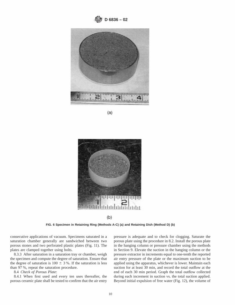
6.8 Specimen Retaining Rings—Specimens tested usingMethods A, B, and C shall be retained on the porous plate ormembrane using a retaining ring at least 5 mm in height and 25mm in inside diameter. The wall thickness shall be sufficient toretain the soil without visible distortion. A photograph of aspecimen in a typical retaining ring is shown in Fig. 6a.Retaining rings are typically constructed from stainless steel,acrylic, or polyvinyl chloride.
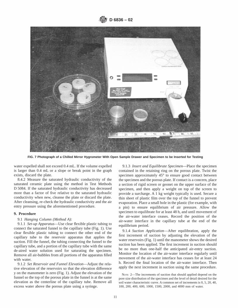
6.9 Chilled Mirror Hygrometer (Method D)—A chilledmirror hygrometer (also known as a chilled mirror psychrom-eter) shall be used to measure water activity to within 0.001.The chilled mirror hygrometer must be able to test specimenswith a diameter of at least 20 mm and height of at least 5 mm.Water activity obtained from the chilled mirror hygrometershall be converted to total suction using the Kelvin equation. Aphotograph of a chilled mirror hygrometer is shown in Fig. 7.
6.10 Specimen Retaining Dish (Method D)—Specimenstested using Method D shall be contained in a specimenretaining dish with a diameter of at least 20 mm and height ofat least 5 mm. The dish shall be made of a non-porous andnon-corroding material such as stainless steel or plastic. Aphotograph of a specimen in a retaining dish is shown in Fig.6b.
6.11 Moisture Content Container—A container meeting therequirements outlined in Method D 2216 shall be provided fordetermination of water content.
FIG. 1 Schematic of Hanging Column Apparatus
D 6836 – 02
4
6.12 Balance—For Methods A-C, a balance shall be usedthat has a minimum capacity of 200 g and a sensitivity of 0.01g. For Method D, a balance shall be used that has a minimumcapacity of 50 g and a sensitivity of 0.001 g. All balances shallmeet the requirements of Specification D 4753.
6.13 Desiccator—A desiccator shall be provided that hassuitable size to hold specimens for cooling after removal fromthe oven. A desiccator is only recommended when moisturecontainers having close-fitting lids are not used (see MethodD 2216).
6.14 Drying Oven—A thermostatically controlled dryingoven capable of maintaining temperature at 1106 5°C as perrequirements of Method D 2216.
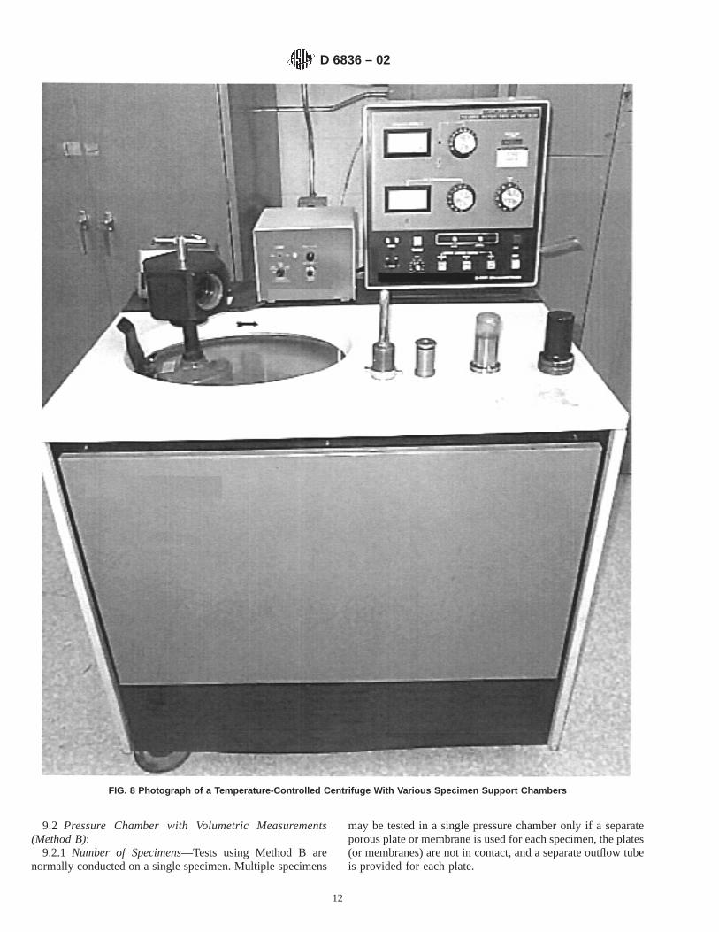
6.15 Temperature Controlled Centrifuge (Method E)—Athermostatically controlled centrifuge capable of maintaining atemperature of 206 3°C when operated between 0-10 000RPM. A photograph of a centrifuge is shown in Fig. 8 withsealed sample support chamber and calibrated water collectiontube. The centrifuge shall include a measurement device forrecording outflow in the support chamber to the nearest 0.1 mLwhile the specimen is under centrifugation. A strobe lightapparatus is normalized used for this purpose.
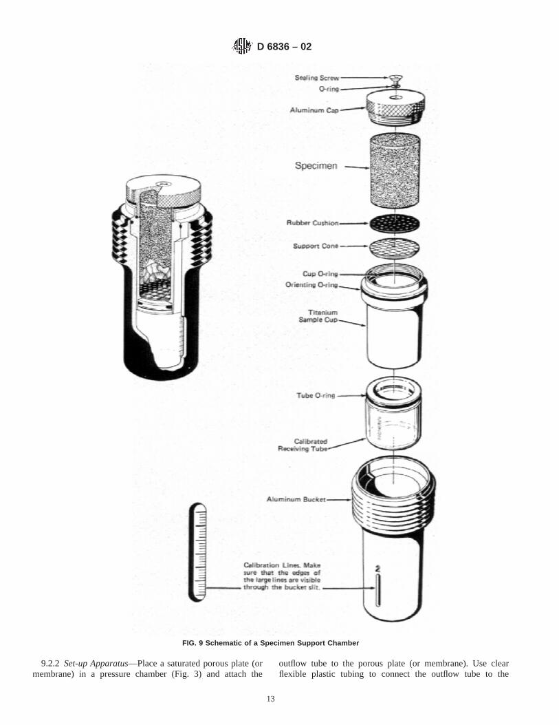
6.16 Specimen Support Chamber (Method E)—A chamberused to retain the specimen and the calibrated cylinder used tocollect the displaced water. A schematic of a specimen supportchamber is shown in Fig. 9.
Specimen is contained in a retaining ring.
FIG. 2 Photograph of Funnel Used for Hanging Column Apparatus.
D 6836 – 02
5
6.17 Saturation Tray, Chamber, or Apron (Methods A-E)—Plates, membranes and specimens are saturated in a saturationtray, a saturation chamber, or directly in pressure chamberusing a saturation apron. Trays shall have a depth greater thanthe sum of the specimen height and thickness of the porousplate (or membrane). Saturation chambers are vessels filledwith water in which a specimen in a retaining ring can beinundated for saturation. A vacuum is applied to the water in asaturation chamber using an external device. A saturation apronin the pressure chamber may be used to impound water arounda specimen for saturation. Aprons are only used for saturatingspecimens.
6.18 Miscellaneous Tools—wire saw, beveled straightedge,spatula, and other small tools for trimming test specimens, 10mL and 100 mL graduated cylinders, 25 mL syringe.
6.19 Laboratory Environment—The laboratory temperatureshall be maintained within6 3°C during the test. Theapparatus shall be shielded from directly sunlight or othersources of heat that may cause variations in temperature. Ifvery precise measurements are required, the hanging column orpressure chamber may be isolated in a thermally insulated box.
7. Reagents
7.1 Saturating Liquid:7.1.1 The saturating liquid is used to saturate the porous
plates and membranes, the specimen, and the outflow measur-ing components of the apparatus.
7.1.2 The saturating liquid should be specified by therequestor. If no specific type of saturating water is specified by
the requestor, the water shall be deaired 0.0025 M CaCl2
solution or tap water. Distilled or deionized water shall not beused unless specified by the requestor. A biocide may be addedto the water to minimize microbial growth during the test. If abiocide is added, the type and concentration of the biocide shallbe included in the report.
7.1.3 Deaired Water—Deaired water shall be used. Water isusually deaired by boiling, spraying a fine mist of water into anevacuated vessel attached to a vacuum source, or by forcefulagitation of water in a container attached to a vacuum source.To prevent dissolution of air back into the water, deaired watershall not be exposed to the atmosphere for prolonged periods.
8. Preparation
8.1 Preparation of Specimens:8.1.1 Specific Gravity—Measure the specific gravity of
solids on a sub-sample of the material to be tested followingthe method in Test Method D 854.
8.1.2 Retaining Ring, Dish, or Mold—Measure the insidediameter of the retaining ring, dish, or mold to the nearest 0.1mm at three locations and record the average of these mea-surements as the diameter. Measure the height of the retainingring, dish (inside height for dish), or mold to the nearest 0.1mm at three locations and record the average of these mea-surements as the height. Weigh the retaining ring, dish, or moldand record its weight to the nearest 0.01 g (ring) or 0.001 g(dish).
8.1.3 Specimens Prepared from Disturbed Samples—Airdry and crush a representative sub-sample that has a mass at
Schematic of pressure chambers with ceramic porous plates: (a) conventional chamber for single or multiple specimens and (b) chamber for single specimen
FIG. 3 Schematic of Pressure Chambers With Ceramic Porous Plates
D 6836 – 02
6
least twice that required to fill the specimen retaining ring. Thesample may be crushed following the procedure described inPractice D 421. Remove all particles from the crushed sub-sample having a diameter exceeding one-half the height of theretaining ring. If requested, moisten the sample to the gravi-metric water content specified using tap water. Prepare aspecimen by placing a known mass of the moistened sub-sample into the retaining ring (Methods A-D) or a specimenmold (Method E). Tap or compact the soil to the densityspecified by the requestor. Trim the upper surface of thespecimen so that it is level with the top of the retaining ring ormold. Weigh the specimen in the retaining ring or mold andrecord the weight to the nearest 0.01 g. Measure the gravimet-ric water content of the remaining material using MethodD 2216.
8.1.4 Specimens Prepared from Undisturbed Samples—ForMethods A-D, place the undisturbed sample on the bench andgently place a retaining ring on the surface of soil. Usetrimming tools to gently remove soil that protrudes beyond theedge of the retaining ring so that the ring can slide over the soilspecimen with little effort. Continue trimming until the soil fillsthe retaining ring. Trim the top of the specimen flush with thetop of the retaining ring. Weigh the specimen in the retainingring and record the weight to the nearest 0.01 g. Measure thegravimetric water content of the remaining material usingMethod D 2216. This procedure is also used to prepare
specimens for testing in the chilled mirror hygrometer afterbeing tested in the hanging column or pressure extractor.
8.1.4.1 A similar procedure is followed to prepare speci-mens for Method E, except no trimming ring or dish isemployed. Specimens are trimmed from the undisturbedsample to form a right circular cylinder that fits inside thespecimen support chamber. Typically specimens are 38 mm indiameter and 51 mm long (Fig. 9). When trimming is complete,measure the height of the specimen at three locations to thenearest 0.1 mm, and record the average of these measurementsas the height. Similarly, measure the diameter of the specimenat three locations to the nearest 0.1 mm, and record the averageof these measurements as the diameter. Weigh the specimen tothe nearest 0.01 g. The sides of the trimmed specimen arewrapped in unsintered teflon tape. Stainless steel screens (220mesh) are placed on the ends of the specimen.
8.1.5 Specimens Compacted in the Laboratory—Compactthe specimen to the specified water content and density usingthe method of compaction specified by the requestor. ForMethods A-D, place the compacted specimen on the bench andgently place a retaining ring on the surface of soil. Usetrimming tools to gently remove soil that protrudes beyond theedge of the retaining ring so that the ring can slide over the soilspecimen with little effort. Continue trimming until the soil fillsthe retaining ring. Trim the top of the specimen flush with thetop of the retaining ring. Weigh the specimen in the retaining
Schematic of pressure chambers with ceramic porous plates: (a) conventional chamber for single or multiple specimens and (b) chamber for single specimen
FIG. 3 Schematic of Pressure Chambers With Ceramic Porous Plates (continued)
D 6836 – 02
7
ring and record the weight to the nearest 0.01 g. Measure thegravimetric water content of the remaining material usingMethod D 2216.
8.1.5.1 A similar procedure is followed to prepare speci-mens for Method E, except no trimming ring or dish isemployed. Specimens are trimmed from the compacted soil toform a right circular cylinder that fits inside the specimensupport chamber. Typically specimens are 38 mm in diameterand 51 mm long (Fig. 9). When trimming is complete, measurethe height of the specimen at three locations to the nearest 0.1mm, and record the average of these measurements as theheight. Similarly, measure the diameter of the specimen atthree locations to the nearest 0.1 mm, and record the average ofthese measurements as the diameter. Weigh the specimen to thenearest 0.01 g. The sides of the trimmed specimen are wrappedin unsintered teflon tape. Stainless steel screens (220 mesh) areplaced on the ends of the specimen.
8.2 Saturation of Funnel, Porous Plate, or Membrane:8.2.1 Hanging Column (Method A)—Immerse the funnel
containing the porous plate in a saturation chamber filled withdeaerated water under a vacuum of at least 75 kPa (Fig. 10).The funnel shall be immersed for at least 24 h and until no airbubbles are visible.
8.2.2 Porous Plates (Methods B and C)—Porous platesshall be submerged in a tray of deaired water or in a saturationchamber under vacuum for a period of at least 24 h and untilno gas bubbles are visible. If a saturation chamber is used, the
ceramic plates shall initially be soaked for 1 h in asaturationtray and then transferred to the saturation chamber. Duringsaturation, a vacuum of at least 75 kPa shall be applied to thechamber for 24 h. At the end of the 24 h period, the vacuumshall be removed and re-applied, and the specimen inspectedfor escaping gas bubbles for 1 h. Repeat this procedure until noair bubbles are observed for at least two consecutive applica-tions of vacuum.
8.2.3 Porous Membrane (Methods B and C)—Porous mem-branes are delicate and must be handled with care to preventdamage. A new membrane shall be used for each test. Beforehandling, porous membranes shall be carefully placed in a panof warm water for at least 30 min to permit softening. Thesoftening water shall be the same water used for saturation.After softening, saturate the porous membrane by submergingin a tray of deaired water for at least 24 h and until no gasbubbles are visible.
8.3 Saturation of Specimen (Methods A-E):8.3.1 Specimens shall be saturated by inundation in a
saturation tray, a saturation chamber, or directly in the hangingcolumn or pressure chamber. The specimen should be main-tained within the retaining ring during saturation to preventdistortion or sloughing. Specimens that are sufficiently cohe-sive can be placed in the saturation tray on top of a porousmaterial (perforated plastic, wire screen, or non-woven geo-textile) without the accompanying ceramic plate. Non-cohesivespecimens generally need to be saturated while in contact with
FIG. 4 Photographs of a Multiple-Specimen Pressure Chamber
D 6836 – 02
8
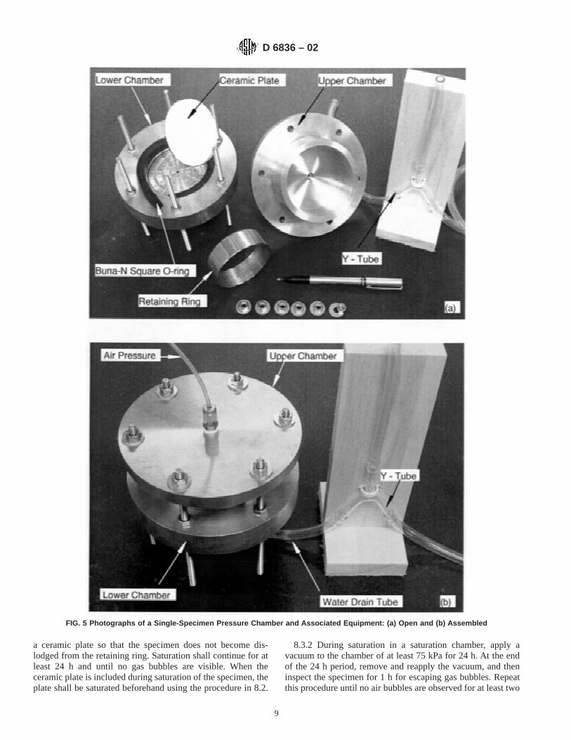
a ceramic plate so that the specimen does not become dis-lodged from the retaining ring. Saturation shall continue for atleast 24 h and until no gas bubbles are visible. When theceramic plate is included during saturation of the specimen, theplate shall be saturated beforehand using the procedure in 8.2.
8.3.2 During saturation in a saturation chamber, apply avacuum to the chamber of at least 75 kPa for 24 h. At the endof the 24 h period, remove and reapply the vacuum, and theninspect the specimen for 1 h for escaping gas bubbles. Repeatthis procedure until no air bubbles are observed for at least two
FIG. 5 Photographs of a Single-Specimen Pressure Chamber and Associated Equipment: (a) Open and (b) Assembled
D 6836 – 02
9
consecutive applications of vacuum. Specimens saturated in asaturation chamber generally are sandwiched between twoporous stones and two perforated plastic plates (Fig. 11). Theplates are clamped together using bolts.
8.3.3 After saturation in a saturation tray or chamber, weighthe specimen and compute the degree of saturation. Ensure thatthe degree of saturation is 1006 3 %. If the saturation is lessthan 97 %, repeat the saturation procedure.
8.4 Check of Porous Plate:8.4.1 When first used and every ten uses thereafter, the
porous ceramic plate shall be tested to confirm that the air entry
pressure is adequate and to check for clogging. Saturate theporous plate using the procedure in 8.2. Install the porous platein the hanging column or pressure chamber using the methodsin Section 9. Elevate the suction in the hanging column or thepressure extractor in increments equal to one-tenth the reportedair entry pressure of the plate or the maximum suction to beapplied using the apparatus, whichever is lower. Maintain eachsuction for at least 30 min, and record the total outflow at theend of each 30 min period. Graph the total outflow collectedduring each increment in suction vs. the total suction applied.Beyond initial expulsion of free water (Fig. 12), the volume of
FIG. 6 Specimen in Retaining Ring (Methods A-C) (a) and Retaining Dish (Method D) (b)
D 6836 – 02
10
water expelled shall not exceed 0.4 mL. If the volume expelledis larger than 0.4 mL or a slope or break point in the graphexists, discard the plate.
8.4.2 Measure the saturated hydraulic conductivity of thesaturated ceramic plate using the method in Test MethodsD 5084. If the saturated hydraulic conductivity has decreasedmore than a factor of five relative to the saturated hydraulicconductivity when new, cleanse the plate or discard the plate.After cleansing, re-check the hydraulic conductivity and the airentry pressure using the aforementioned procedure.
9. Procedure
9.1 Hanging Column (Method A):9.1.1 Set-up Apparatus—Use clear flexible plastic tubing to
connect the saturated funnel to the capillary tube (Fig. 1). Useclear flexible plastic tubing to connect the other end of thecapillary tube to the reservoir apparatus that applies thesuction. Fill the funnel, the tubing connecting the funnel to thecapillary tube, and a portion of the capillary tube with the samede-aired water solution used for saturating the specimen.Remove all air-bubbles from all portions of the apparatus filledwith water.
9.1.2 Set Reservoir and Funnel Elevation—Adjust the rela-tive elevation of the reservoirs so that the elevation differencey on the manometer is zero (Fig. 1). Adjust the elevation of thefunnel so the top of the porous plate in the funnel is at the sameelevation as the centerline of the capillary tube. Remove allexcess water above the porous plate using a syringe.
9.1.3 Insert and Equilibrate Specimen—Place the specimencontained in the retaining ring on the porous plate. Twist thespecimen approximately 45° to ensure good contact betweenthe specimen and the porous plate. If contact is a concern, placea section of rigid screen or geonet on the upper surface of thespecimen, and then apply a weight on top of the screen toprovide a surcharge. A 1 kg weight typically is used. Secure athin sheet of plastic film over the top of the funnel to preventevaporation. Place a small hole in the plastic (for example, witha pin) to ensure equilibrium of air pressure. Allow thespecimen to equilibrate for at least 48 h, and until movement ofthe air-water interface ceases. Record the position of theair-water interface in the capillary tube at the end of theequilibrium period.
9.1.4 Suction Application—After equilibration, apply thefirst increment of suction by adjusting the elevation of thewater reservoirs (Fig. 1) until the manometer shows the desiredsuction has been applied. The first increment in suction shouldbe no more than one-half the anticipated air-entry suction.Monitor the location of the air-water interface regularly untilmovement of the air-water interface has ceases for at least 24h. Record the final location of the air-water interface. Thenapply the next increment in suction using the same procedure.
NOTE 2—The increments of suction that should applied depend on thepore size distribution of the specimen and the level of detail desired for thesoil water characteristic curve. A common set of increments is 0, 5, 20, 40,100, 200, 400, 600, 1000, 1500, 2000, and 4000 mm of water.
FIG. 7 Photograph of a Chilled Mirror Hygrometer With Open Sample Drawer and Specimen to be Inserted for Testing
D 6836 – 02
11
9.2 Pressure Chamber with Volumetric Measurements(Method B):
9.2.1 Number of Specimens—Tests using Method B arenormally conducted on a single specimen. Multiple specimens
may be tested in a single pressure chamber only if a separateporous plate or membrane is used for each specimen, the plates(or membranes) are not in contact, and a separate outflow tubeis provided for each plate.
FIG. 8 Photograph of a Temperature-Controlled Centrifuge With Various Specimen Support Chambers
D 6836 – 02
12
9.2.2 Set-up Apparatus—Place a saturated porous plate (ormembrane) in a pressure chamber (Fig. 3) and attach the
outflow tube to the porous plate (or membrane). Use clearflexible plastic tubing to connect the outflow tube to the
FIG. 9 Schematic of a Specimen Support Chamber
D 6836 – 02
13
capillary tube as shown in Fig. 13. Saturate the outflow tubing, all connections between the outflow tubing and the porous
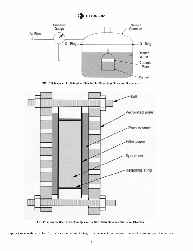
FIG. 10 Schematic of a Saturation Chamber for Saturating Plates and Specimens
FIG. 11 Assembly Used to Contain Specimens When Saturating in a Saturation Chamber
D 6836 – 02
14
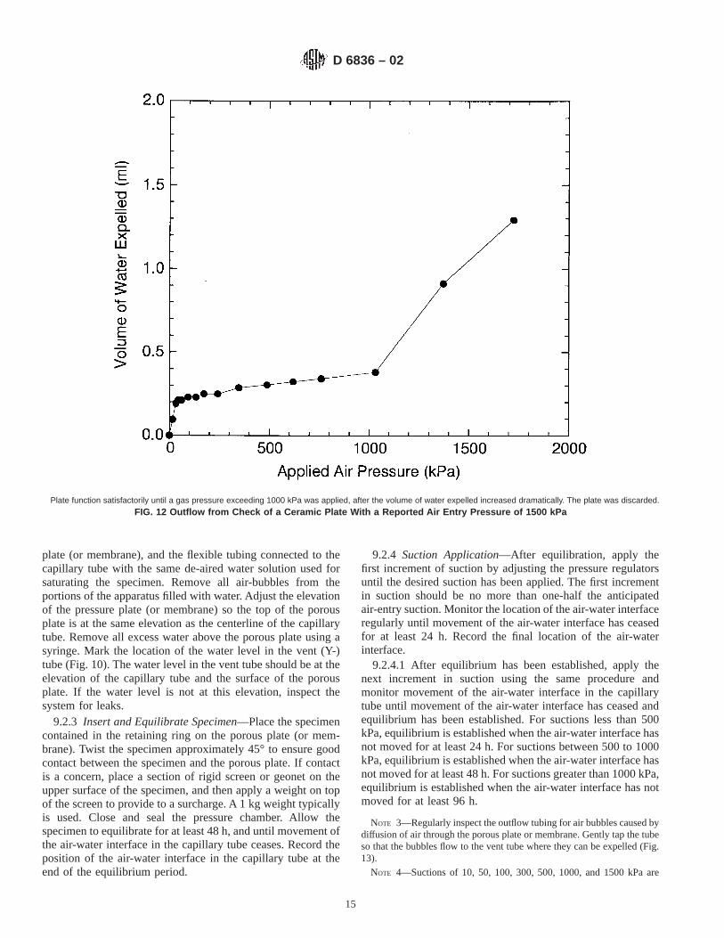
plate (or membrane), and the flexible tubing connected to thecapillary tube with the same de-aired water solution used forsaturating the specimen. Remove all air-bubbles from theportions of the apparatus filled with water. Adjust the elevationof the pressure plate (or membrane) so the top of the porousplate is at the same elevation as the centerline of the capillarytube. Remove all excess water above the porous plate using asyringe. Mark the location of the water level in the vent (Y-)tube (Fig. 10). The water level in the vent tube should be at theelevation of the capillary tube and the surface of the porousplate. If the water level is not at this elevation, inspect thesystem for leaks.
9.2.3 Insert and Equilibrate Specimen—Place the specimencontained in the retaining ring on the porous plate (or mem-brane). Twist the specimen approximately 45° to ensure goodcontact between the specimen and the porous plate. If contactis a concern, place a section of rigid screen or geonet on theupper surface of the specimen, and then apply a weight on topof the screen to provide to a surcharge. A 1 kg weight typicallyis used. Close and seal the pressure chamber. Allow thespecimen to equilibrate for at least 48 h, and until movement ofthe air-water interface in the capillary tube ceases. Record theposition of the air-water interface in the capillary tube at theend of the equilibrium period.
9.2.4 Suction Application—After equilibration, apply thefirst increment of suction by adjusting the pressure regulatorsuntil the desired suction has been applied. The first incrementin suction should be no more than one-half the anticipatedair-entry suction. Monitor the location of the air-water interfaceregularly until movement of the air-water interface has ceasedfor at least 24 h. Record the final location of the air-waterinterface.
9.2.4.1 After equilibrium has been established, apply thenext increment in suction using the same procedure andmonitor movement of the air-water interface in the capillarytube until movement of the air-water interface has ceased andequilibrium has been established. For suctions less than 500kPa, equilibrium is established when the air-water interface hasnot moved for at least 24 h. For suctions between 500 to 1000kPa, equilibrium is established when the air-water interface hasnot moved for at least 48 h. For suctions greater than 1000 kPa,equilibrium is established when the air-water interface has notmoved for at least 96 h.
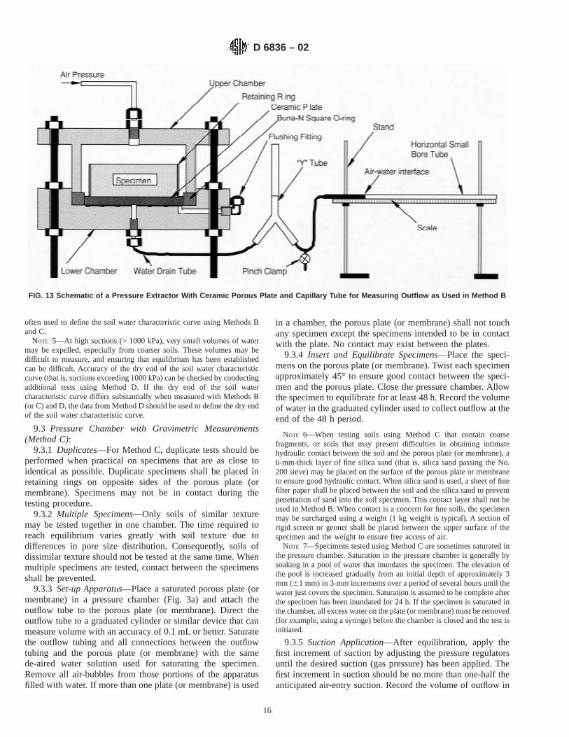
NOTE 3—Regularly inspect the outflow tubing for air bubbles caused bydiffusion of air through the porous plate or membrane. Gently tap the tubeso that the bubbles flow to the vent tube where they can be expelled (Fig.13).
NOTE 4—Suctions of 10, 50, 100, 300, 500, 1000, and 1500 kPa are
Plate function satisfactorily until a gas pressure exceeding 1000 kPa was applied, after the volume of water expelled increased dramatically. The plate was discarded.
FIG. 12 Outflow from Check of a Ceramic Plate With a Reported Air Entry Pressure of 1500 kPa
D 6836 – 02
15
often used to define the soil water characteristic curve using Methods Band C.
NOTE 5—At high suctions (> 1000 kPa), very small volumes of watermay be expelled, especially from coarser soils. These volumes may bedifficult to measure, and ensuring that equilibrium has been establishedcan be difficult. Accuracy of the dry end of the soil water characteristiccurve (that is, suctions exceeding 1000 kPa) can be checked by conductingadditional tests using Method D. If the dry end of the soil watercharacteristic curve differs substantially when measured with Methods B(or C) and D, the data from Method D should be used to define the dry endof the soil water characteristic curve.
9.3 Pressure Chamber with Gravimetric Measurements(Method C):
9.3.1 Duplicates—For Method C, duplicate tests should beperformed when practical on specimens that are as close toidentical as possible. Duplicate specimens shall be placed inretaining rings on opposite sides of the porous plate (ormembrane). Specimens may not be in contact during thetesting procedure.
9.3.2 Multiple Specimens—Only soils of similar texturemay be tested together in one chamber. The time required toreach equilibrium varies greatly with soil texture due todifferences in pore size distribution. Consequently, soils ofdissimilar texture should not be tested at the same time. Whenmultiple specimens are tested, contact between the specimensshall be prevented.
9.3.3 Set-up Apparatus—Place a saturated porous plate (ormembrane) in a pressure chamber (Fig. 3a) and attach theoutflow tube to the porous plate (or membrane). Direct theoutflow tube to a graduated cylinder or similar device that canmeasure volume with an accuracy of 0.1 mL or better. Saturatethe outflow tubing and all connections between the outflowtubing and the porous plate (or membrane) with the samede-aired water solution used for saturating the specimen.Remove all air-bubbles from those portions of the apparatusfilled with water. If more than one plate (or membrane) is used
in a chamber, the porous plate (or membrane) shall not touchany specimen except the specimens intended to be in contactwith the plate. No contact may exist between the plates.
9.3.4 Insert and Equilibrate Specimens—Place the speci-mens on the porous plate (or membrane). Twist each specimenapproximately 45° to ensure good contact between the speci-men and the porous plate. Close the pressure chamber. Allowthe specimen to equilibrate for at least 48 h. Record the volumeof water in the graduated cylinder used to collect outflow at theend of the 48 h period.
NOTE 6—When testing soils using Method C that contain coarsefragments, or soils that may present difficulties in obtaining intimatehydraulic contact between the soil and the porous plate (or membrane), a6-mm-thick layer of fine silica sand (that is, silica sand passing the No.200 sieve) may be placed on the surface of the porous plate or membraneto ensure good hydraulic contact. When silica sand is used, a sheet of finefilter paper shall be placed between the soil and the silica sand to preventpenetration of sand into the soil specimen. This contact layer shall not beused in Method B. When contact is a concern for fine soils, the specimenmay be surcharged using a weight (1 kg weight is typical). A section ofrigid screen or geonet shall be placed between the upper surface of thespecimen and the weight to ensure free access of air.
NOTE 7—Specimens tested using Method C are sometimes saturated inthe pressure chamber. Saturation in the pressure chamber is generally bysoaking in a pool of water that inundates the specimen. The elevation ofthe pool is increased gradually from an initial depth of approximately 3mm (61 mm) in 3-mm increments over a period of several hours until thewater just covers the specimen. Saturation is assumed to be complete afterthe specimen has been inundated for 24 h. If the specimen is saturated inthe chamber, all excess water on the plate (or membrane) must be removed(for example, using a syringe) before the chamber is closed and the test isinitiated.
9.3.5 Suction Application—After equilibration, apply thefirst increment of suction by adjusting the pressure regulatorsuntil the desired suction (gas pressure) has been applied. Thefirst increment in suction should be no more than one-half theanticipated air-entry suction. Record the volume of outflow in
FIG. 13 Schematic of a Pressure Extractor With Ceramic Porous Plate and Capillary Tube for Measuring Outflow as Used in Method B
D 6836 – 02
16
the graduated cylinder regularly until water has not beenexpelled for at least 24 h.
9.3.5.1 After equilibrium has been established, clamp theoutflow tube to prevent backflow, exhaust the pressure, andopen the pressure chamber. Quickly remove the specimens andtheir retaining rings from the porous plate (or membrane) usinga wide-blade spatula. Immediately weigh the specimens. If thesame specimens are to be used throughout the test, place the
specimens back on the porous plate (or membrane) and twisteach specimen approximately 45° to ensure good contact.Alternatively, a new specimen may be used for each incrementprovided that that all specimens used to define a soil watercharacteristic curve are practically identical. Close and seal thepressure chamber, remove the clamp on the outflow tube, andquickly raise the gas pressure to the next suction. Monitor theoutflow volume until outflow has ceased for at least 24 h.
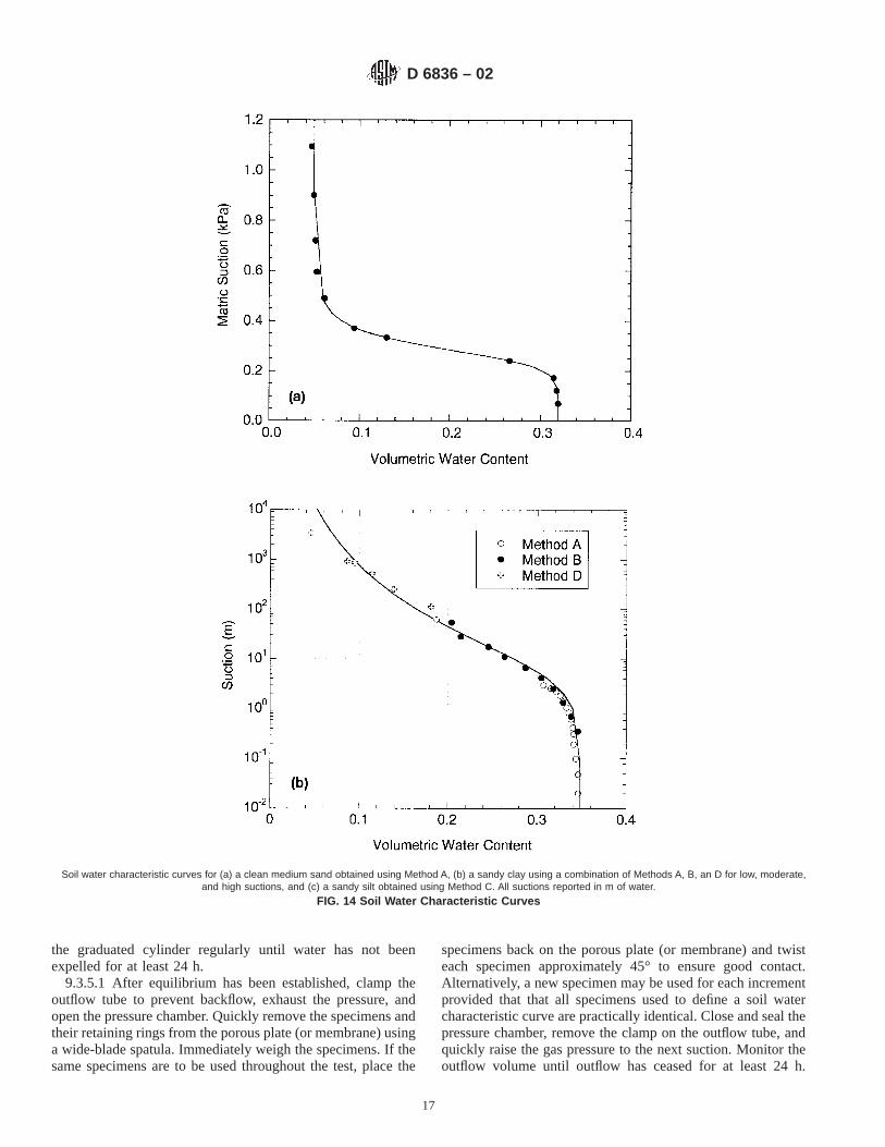
Soil water characteristic curves for (a) a clean medium sand obtained using Method A, (b) a sandy clay using a combination of Methods A, B, an D for low, moderate,and high suctions, and (c) a sandy silt obtained using Method C. All suctions reported in m of water.
FIG. 14 Soil Water Characteristic Curves
D 6836 – 02
17
Repeat this procedure until all suctions specified by therequestor have been determined. When suctions between 500to 1000 kPa are being established, monitor the outflow volumeuntil the outflow has ceased for 48 h. For suctions greater than1000 kPa, monitor the outflow volume until outflow has ceasedfor 96 h. If concern exists regarding equilibrium at highsuctions, check this portion of the soil water characteristiccurve using the procedure described in Note 5.
NOTE 8—Re-establishing hydraulic contact between the soil specimenand the plate (or membrane) can be difficult after suction has been applied.If concern exists regarding hydraulic contact, separate specimens may beused for each increment. These specimens should be prepared so that theyare as identical as possible. If separate specimens are used, the gravimetricwater content of each specimen should be determined after testing usingthe method in Method D 2216.
9.4 Chilled Mirror Hygrometer (Method D):9.4.1 Procedure—Place the soil specimen in a retaining dish
and insert the dish into the chilled mirror hygrometer (Fig. 7).Measure the water activity to an accuracy of 0.001 using thehygrometer. Record the water activity.
9.4.1.1 If the soil water characteristic curve is to be deter-mined using a series of specimens prepared at differentvolumetric water contents, measure the water activity of eachspecimen using the hygrometer. Then weigh each specimen tothe nearest 0.001 g and determine the gravimetric water of eachspecimen using Method D 2216.
9.4.1.2 If a single specimen is to be used, measure the wateractivity at the first water content and then allow the specimento dry by exposure to the atmosphere until the next watercontent is achieved. Monitor the change in water content byperiodically measuring the weight of the specimen and dish tothe nearest 0.01 g. After the specimen has dried to the next
water content, record the weight of the dish and specimen tothe nearest 0.001 g, seal the dish, and allow the specimen toequilibrate for 24 h. After equilibration, measure the wateractivity using the hygrometer as described in 9.4.1. Repeat thisprocedure until the water activity has been measured at eachwater content specified by the requestor. After the finalmeasurement of water activity has been made, measure thefinal gravimetric water content of the specimen using themethod in Method D 2216.
9.5 Centrifuge (Method E):9.5.1 Procedure—Place the specimen in the support cham-
ber and seal the chamber (Fig. 9). Record the distance from thecenter of the axis of rotation to the bottom of the specimen(outer radius of rotation) to the nearest 0.1 mm. Record thedistance from the center of the axis of rotation to the top of thespecimen (inner radius of rotation) to the nearest 0.1 mm.Install the support chamber in the centrifuge, and begincentrifugation at an angular velocity corresponding to thelowest suction to be induced (see 10.4). Centrifuge for at least120 min, and periodically record the volume of water displacedthrough centrifugation to the nearest 0.1 mL. Continue cen-trifugation until no additional water is displaced, and record thetotal volume of water displaced to the nearest 0.1 mL. Repeatthe procedure at incrementally higher angular velocities todefine the soil water characteristic curve.
NOTE 9—Angular velocities of 100, 200, 400, 800 and 1500 RPM areoften used to define the soil water characteristic curve using Method E.
10. Calculations
10.1 Saturated Volumetric Content—The water content atzero matric suction is assumed to be the saturated water
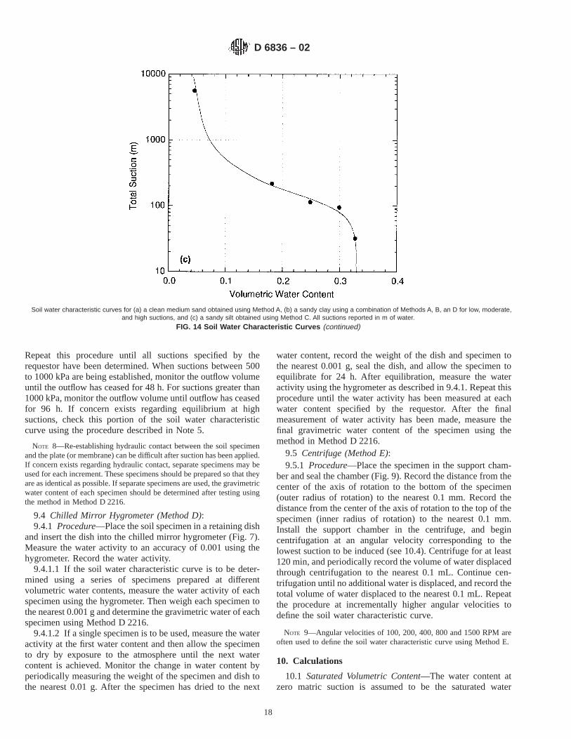
Soil water characteristic curves for (a) a clean medium sand obtained using Method A, (b) a sandy clay using a combination of Methods A, B, an D for low, moderate,and high suctions, and (c) a sandy silt obtained using Method C. All suctions reported in m of water.
FIG. 14 Soil Water Characteristic Curves (continued)
D 6836 – 02
18
content. Compute the saturated gravimetric and volumetricwater contents using the following methods if the test wasconducted using Methods A-E. Saturated specimens are nottested with Method D.
10.1.1 For specimens saturated using a saturation tray or asaturation chamber and then tested using Methods A, B, or E,calculate the saturated gravimetric and volumetric water con-tents using the dry density recorded after preparation of thespecimen, the gravimetric water content at saturation, and thevolume of water imbibed or expelled during the saturationphase. The saturated gravimetric water content is computed as:
wsat 5Msat~1 1 wm!
Mm2 1 (1)
where Mm and wm are the mass and gravimetric watercontent of the moist soil in the retaining ring after the specimenhas been prepared (trimmed or compacted in ring),Msat is themass of soil in the retaining ring after saturation. The drydensity is computed as:
rd 5Mm
V~1 1 wm!(2)
whereV is the volume of the retaining ring (Methods A andB). For Method E,V is the volume of the specimen and iscomputed as:
V 5pd2L
4 (3)
whered is the diameter of the specimen andL is the heightof the specimen, as described in 8.1. The saturated volumetricwater content is computed as:
usat 5rd
rwwsat (4)
whererw is the density of water.10.1.2 For specimens saturated directly in a pressure extrac-
tor using a saturating apron, compute the saturated volumetricand gravimetric water contents as:
usat 5 1 2rd
Gsrw(5)
and
wsat 5rw
rdusat (6)
whererd is computed using Eq 2.10.2 Water Contents at Other Suctions:10.2.1 Methods A and B—Compute the volumetric water
content corresponding to eachith increment in suction,ui, as:
ui 5 ui21 2 ~xi 2 xi21!FV (7)
whereui-1 is the volumetric water content at the previoussuction, xi is the location of the air-water interface afterequilibrium has been established at theith suction as describedin 9.2.4, xi-1 is the location of the air-water interface afterequilibrium was established for the previous increment insuction, F is the scale factor for the capillary tube relatingvolume to displacement of the air-water interface, andV is thevolume of the sample. Wheni = 1, ui-1= usat and xi-1 is theinitial reading for the air-water interface that was recorded afterinitially establishing equilibrium, as described in 9.2.3. The
gravimetric water content corresponding to each volumetricwater content can be computed as:
wi 5rw
rdui (8)
10.2.2 Method C—If duplicate specimens are tested, thegravimetric water content of the two replicate specimens shallbe averaged for each suction, and the average shall be reportedas the gravimetric water content for the applied suction. Thevolumetric water content corresponding to each gravimetricwater content can be computed using:
u 5rd
rww (9)
10.2.3 Method E—Compute the volumetric water contentcorresponding to eachith increment in suction,ui, as:
ui 5 ui21 2Vdi
V (10)
whereui-1 is the volumetric water content at the previoussuction,Vdi is the volume of water displaced by theith suction(or ith angular velocity), andV is the volume of the specimen(Eq 3). Compute theith suction (in kPa) induced as:
ci 5 b~rw 2 rg!vi2~rb
2 2 rt2! (11)
whererw is the density of the pore liquid (typically water,1.0 kg/L),rg is the density of the pore gas (typically assumedto be zero),v is the angular velocity of the centrifuge (rpm),rb
is the outer radius of rotation (m),rt is the inner radius ofrotation (m), andb is a constant = 0.00553.
10.3 Total Suctions and Water Content—MethodD—Calculate the total suction for theith test (cti) using thewater activity reported by the chilled mirror hygrometer andthe Kelvin equation:
cti 5RTM 1n~aw! (12)
whereaw is the water activity,R is the gas constant,T is thelaboratory temperature (°K), andM is the molecular mass ofwater. The value ofR/M is 461 kPa/°K. Temperature in °K isobtained by adding 273° to the temperature in °C.
10.3.1 When suctions corresponding to various water con-tents are measured using a single specimen (that is, byrepeatedly drying the specimen), the gravimetric water contentcorresponding to theith measurement of suction,wi, is com-puted as:
wi 5 wo 1Mi 2 Mo
rdV(13)
wherewo is the gravimetric water content determined usingMethod D 2216 for the first suction measurement,Mo is themass of the specimen for the first suction measurement,Mi isthe mass of the specimen for theith suction measurement,rd isthe dry density at which the specimen was prepared, andV isthe volume of the specimen. Volumetric water contents corre-sponding to the gravimetric water contents can be determinedusing Eq 9.
10.3.2 When suctions are measured on individual speci-mens, the gravimetric water content of each specimen ismeasured using Method D 2216 after testing in the hygrometer.Volumetric water contents corresponding to these gravimetricwater contents can be determined using Eq 9.
D 6836 – 02
19
10.4 Saturation—If the soil water characteristic curve is tobe reported in terms of saturation (S) rather than water content,compute the degree of saturation corresponding to each volu-metric water content using:
S5u
1 2rd
Gsrw
(14)
or to convert gravimetric water content to saturation, use:
S5w
rw
rd2
1Gs
(15)
11. Report
11.1 The report shall include the following information:11.1.1 Sample identifying information.11.1.2 The type of water used to saturate and test the soil
specimens.11.1.3 The method of saturation (tray, saturation chamber,
or saturating apron in a pressure chamber).11.1.4 The method used to conduct the test (for example,
Method A, B, C, D or E). For Methods B and C, state whethera porous plate or porous membrane was used, the air entrypressure of the porous plate or membrane. For Method D, statethe brand and model of the hygrometer that was used. ForMethod E, state the manufacturer and model number for thecentrifuge and specimen support chamber.
11.1.5 A description of the soil, any special characteristicsof the specimen, and the selection and/or processing procedure(for example, removal of stones). For compacted materials,provide descriptive information on the method of compaction,the compaction water content, and the compacted dry unitweight.
11.1.6 Dimensions of test specimens.11.1.7 Time required to reach equilibrium at each pressure
step.11.1.8 Approximate temperature of the soil during the test
procedure (typically the air temperature of the laboratory) tothe nearest 1°C.
11.1.9 A table reporting the gravimetric and volumetricwater content corresponding to each suction.
11.1.10 For Methods A and B, report the gravimetric watercontent of the specimen after the last increment in suction wasapplied, as measured using Method D 2216. Report the corre-sponding volumetric water content, and the difference betweenthis volumetric water content and that computed using Eq 6 forthe final increment in suction.
11.1.11 The soil water characteristic curve; that is, a graphshowing volumetric water content, gravimetric water content,or saturation as a function of suction. Three examples of soilwater characteristic curves are shown in Fig. 12. The soil watercharacteristic curve in Fig. 12a was determined using MethodA. Methods A, B, and D were combined to determine the soilwater characteristic curve shown in Fig. 12b. The soil watercharacteristic curve in Fig. 12b illustrates how Method D canbe used to define the dry end of the curve and Method A can beused to define the portion near saturation. The good matchbetween the data from Methods B and D at the dry endindicates that equilibrium was established at the higher suc-tions when Method B was used. An example of a soil watercharacteristic curve determined solely with Method D is shownin Fig. 12c.
12. Precision and Bias
12.1 Precision—Test data on precision are not presenteddue to the nature of the geological materials tested by this testmethod. Having ten or more laboratories participate in around-robin testing program is considered to be infeasible andtoo costly. Also, producing multiple specimens that haveuniform physical properties is considered infeasible and toocostly. Any variation observed in the data is just as likely to bedue to specimen variation as to operator or laboratory testingvariation.
12.1.1 Subcommittee D18.04 on Hydrologic Properties ofSoil and Rock is seeking data from the users of this test methodthat might be used to make a limited statement on precision.
13. Keywords
13.1 capillary pressure; chilled mirror hygrometer; gravi-metric water content; hanging column; matric potential; matricsuction; pressure membrane; pressure plate; soil; soil watercharacteristic curve; suction; total suction; volumetric watercontent; water activity
ASTM International takes no position respecting the validity of any patent rights asserted in connection with any item mentionedin this standard. Users of this standard are expressly advised that determination of the validity of any such patent rights, and the riskof infringement of such rights, are entirely their own responsibility.
This standard is subject to revision at any time by the responsible technical committee and must be reviewed every five years andif not revised, either reapproved or withdrawn. Your comments are invited either for revision of this standard or for additional standardsand should be addressed to ASTM International Headquarters. Your comments will receive careful consideration at a meeting of theresponsible technical committee, which you may attend. If you feel that your comments have not received a fair hearing you shouldmake your views known to the ASTM Committee on Standards, at the address shown below.
This standard is copyrighted by ASTM International, 100 Barr Harbor Drive, PO Box C700, West Conshohocken, PA 19428-2959,United States. Individual reprints (single or multiple copies) of this standard may be obtained by contacting ASTM at the aboveaddress or at 610-832-9585 (phone), 610-832-9555 (fax), or [email protected] (e-mail); or through the ASTM website(www.astm.org).
D 6836 – 02
20


![[Architecture eBook] 04.09 - Architectural Record (2004.09)](https://static.fdocuments.us/doc/165x107/548d3dfcb47959f1138b460e/architecture-ebook-0409-architectural-record-200409.jpg)


