
Standard Operating Procedures Manual for ... - pci.org
103
Standard Operating Procedures Manual for Inspectors Prestressed Concrete Members NORTH CAROLINA DEPARTMENT OF TRANSPORTATION Structural Materials Group Manufactured Products
Transcript of Standard Operating Procedures Manual for ... - pci.org

Standard Operating Procedures Manual for Inspectors
Prestressed Concrete Members
NORTH CAROLINA DEPARTMENT OF TRANSPORTATIONStructural Materials Group
Manufactured Products

North Carolina Department of Transportation Materials and Tests Unit Structural Materials Group 1801 Blue Ridge Road Raleigh, NC 27607 Phone: 919-329-4000
Standard Operating Procedures Manufactured Products – Prestressed Concrete
This Standard Operation Procedure Manual presents basic principles the North Carolina Department of Transportation utilizes to ensure that precast prestressed structural members are produced in compliance with plans, approved drawings and standard specifications. Also included in this manual is an example of typical documentation required for inspection procedures.
Prestressed member production is monitored and inspected weekly or as necessary based on product volume and requirements. This SOP provides guidelines for typical member inspection. Standard facility audits are conducted annually. Common facility production practices are evaluated and recorded. Additionally, stockpile material is evaluated, and samples are collected annually for Quality Assurance. Scale calibration checks are conducted twice per year.
NCDOT Materials and Tests technicians are assigned to precast prestressed producing facilities for the purpose of Quality Assurance inspection and are the contact between the NCDOT and the producer. Quality Assurance inspection requires close attention to details and procedures required by NCDOT to verify that the work performed by the producer is the quality required by the Department and the contract.
Producers production practices may differ within each facility. NCDOT does not specify these practices, however, all procedures and workmanship are required to be in accordance with specifications and plans. The technician has the authority to make decisions on acceptance or rejection of materials and members produced, based on specifications, plans and contract special provisions.
This standard does not purport to address all the safety concerns, if any, associated with its use. It is the responsibility of the user of this procedure to establish appropriate safety and health practices and determine the applicability of regulatory limitations prior to use, which includes disposal of hazardous materials in an appropriate manner.

Modification History
Rev# Date Author/Editor/Approver Comments/Reasons:
xx May 2015 Jason Poppe/Darren Scott
Feb 2019 J. Civils
Document Number: Author Document Approver: Version Release Date: Feb, 2019 Next Review Date:

1 REFERENCED DOCUMENTS, ASTM AND STANDARDS 1.1 Standard Specifications: 2018 Section 1078 1.2 ASTM Standards
1.2.1 ASTM A123-08 Hot-Dip Galvanized Coatings 1.2.2 ASTM A775-17 Epoxy Coated Rebar
1.3 AASHTO Standards 1.3.1 AASHTO T-23 - Strength Specimens 1.3.2 AASHTO T-119 - Concrete Slump 1.3.3 AASHTO T-152 - Concrete Air Entrainment 1.3.4 AASHTO T-309 - Concrete Temperature
1.4 Other Standards 1.4.1 Materials & Tests Method Chem C-20.0 Hardened Concrete 1.4.2 Materials & Tests Method Chem C-21.0 Field Test Procedures for Nitrite Ion in
Plastic Concrete 1.4.3 Materials & Tests Method Chem C-22.0 Field Spot Test
2 TERMINOLOGY 2.1 SOP - Standard Operation Procedure 2.2 PPE – Personal Protective Equipment 2.3 NCR – Non-Conformance Report (shared with SMU) 2.4 IR – Informational Report (not shared with SMU) 2.5 M&T – NCDOT Materials & Tests Unit 2.6 Inspector – Inspects and records producing operations, either NCDOT or CEI 2.7 CEI – Contract Engineering Inspector 2.8 SMU – NCDOT Structures Management Unit 2.9 CNI – Calcium Nitrite Ion (also referred to as CaNO2) – Corrosion Inhibitor 2.10 Detensioning – Releasing the tension of the Strands to put Member in Compression 2.11 HiCAMS – NCDOT Highway Construction and Materials System 2.12 Strand – Prestressed concrete steel strand is a twisted steel cable composed of 2, 3, 7 or 19
high strength steel wires that are stress-relieved or stabilized 2.13 RFID – Radio Frequency Identification 2.14 Producer – Prestress Concrete Manufacturer 2.15 PSI – Unit of pressure expressed in pounds of force per square inch of area = Pounds per
Square Inch 2.16 Initial Set – the degree of stiffening of a mixture of cement less than final set. Prestressed
Concrete is 500psi 2.17 Member – Prestressed Concrete item is referred to as a member; can be a Girder, Piles, Deck
Panel, Cored Slab 2.18 Post-Tensioning – done at the construction site; Strands are stressed after the concrete has
been placed and gained sufficient psi.

3 LIMITATIONS AND SAFETY 3.1 Primary safety requirements (PPE) include but are not limited to the following: (additions
may be required by the producer.) • Steel Toe Boots
• Safety Vest
• Hard Hat
• Safety Glasses
3.2 NCDOT Workplace Safety Manual, Safe Operating Procedure 11B-71 – Appendix 8.1 3.3 Use caution during tensioning and de-tensioning operations. Stay in a safe area, use shield,
listen and look for lights and alarm, ensure equipment is out of the way.
4 EQUIPMENT • Tape Measure 100ft, 25ft, folding ruler – Use to measure the length & width of various
members and rebar. • Digital Angle Finder - Use to help identify designated skew of any given member and/or
headers. • T Square - Use to check the members squareness. • Calibrated Thermometer - Use to check the concrete temperature. Requires calibration
every six months • DOT Test Equipment:
• Chace Indicator
• CNI Strips
• CNI test dots
• Distilled water
• Hammer drill
• Digital scale metric/English
• Gallon plastic bags
• Small plastic bags
• CaNO2 stamp • Water Test Strips – Use to take water samples as required monthly at plant locations • HiCAMS Sample Card - Each sample that is brought in from the field must have its own
unique HiCAMS sample card (with a unique HiCAMS number), either attached to the bag or container containing the sample or place inside of said conainer or bag.
• Plant Daily Diary - This ledger is used to record all daily activities performed. It is very important to keep this ledger up to date and easily accessible. Contract number, bridge number, county and tasks performed shall be documented. Each entry should be signed by the inspector performing the work.
• Concrete Casting Log - This log documents concrete placements for individual contracts, bridge number, span location (if known), member type, piece numbers cast, lengths, concrete test data, including slump, air, concrete temperature and air temperature, release strength and acceptance strength, NCR if applicable and approval date. If CNI is required, enter HiCAMS number in appropriate column.
• Tablet – Used for logging information into RFID system and HiCAMS • Scanner – Used for scanning RFID tags on members • Laptop – Used for logging information into RFID system and HiCAMS

5 STANDARD PRESTRESSED MEMBERS AND INSPECTION FORMS 5.1 Prestress Members
• Bulb Tee & Modified Bulb Tee Girders
• Core Slab/Box Beam
• Piles
• Deck Panel
5.2 Inspection Forms • Concrete Bulb Tee Girders – MT Form P3850
• Concrete AASHTO Girders – MT Form 3840 • Concrete Cored Slabs – MT Form P3800 • Concrete Box Beams – MT Form P3810 • Concrete Piles – MT Form P3820 • Concrete Deck Slabs – MT Form P3830 • General Inspection Checklist of Box Beams – MT Form P3100 • Prestress Scale Calibration – MT Form 703 • Prestress Annual Facility Audit Checklist – MT Form P38 • Facility Ownership Update Form 2020
6 QUALITY ASSURANCE PROCESS AND STOCKPILE MATERIAL SAMPLING 6.1 Approved working drawing submittals must be on hand. Go to connect.ncdot.gov
(SharePoint) to retrieve official plans. If plans are not available, then contact the Resident Engineer or their staff to ask for them. Compare these to any Producer supplied shop drawings or contract drawings and note any differences. Have Producer either correct any differences or submit their shop drawings with a list of variances to NCDOT Structure Design for approval on a Project by Project basis. Make sure this approval has been given prior to casting any members for each project.
6.2 Set up folder for files. Use the approved sticker to fill in ALL the following information. Place the sticker on the outside of the folder.
• Contract number
• Project number
• Bridge number
• Station
• County
• Resident Engineer – phone number – email
• M&T records contact – phone number – email
• Contractor
• Letting date
• Producer/Job number
• Approved Concrete Mix Design (project specific mix designs are no longer required)
• Approved De-Tensioning Sequence
• Approved Hold-Down System
• Approved set of plans
• Release strength
• Acceptance strength

6.3 Stockpile Material – See Appendix 8.4 for sampling requirement details. Sampling for QA purposes is typically done once per year during the Annual Facility Audit, or when deemed necessary.
• Reinforcing Steel • Cement • Fly Ash
• Water
• Prestressing Stand
• Aggregate
• Aggregate Gradation
• Corrosion Inhibitor
6.4 Annual Facility Audits are performed by NCDOT Materials and Test technicians annually for currently approved facilities and upon initial facility approval to produce for the North Carolina Department of Transportation. The audit includes, but is not limited to, a review of form condition and dimensions, pallet profile and alignment, concrete batching and testing procedures, scale calibration, plant operations, stressing operations, collection of stockpile samples, batchers evaluation and verifying other required certifications.
7 Standard Operating Procedures 7.1 Bulb Tee and Modified Bulb Tee Inspection 7.2 Cored Slab and Box Beam 7.3 Concrete Piles 7.4 Concrete Deck Panels 7.5 Annual Facility Audit 7.6 RFID Scanning
8 APPENDIX 8.1 Safe Operation Procedures 11B-71 8.2 Prestress Non-Conformance Report Policy 8.3 Entering Samples into HiCAMS 8.4 Quality Assurance Stockpile Material Sampling 8.5 RFID Tag Location on Members


Prestressed SOP section 7.1
Standard Operating Procedure Bulb Tee & Modified Bulb Tee Girder
Production Inspection
OBJECTIVE The Purpose of this SOP is to establish guidelines and uniformity for the inspection, acceptance and reporting of Bulb Tee & Modified Bulb Tee Girder Prestressed Concrete. The guidelines are designed to ensure all technicians/inspectors follow the same procedures and comply with all NCDOT, ASTM and ASSHTO specifications. SAFETY EQUIPMENT AND SAFETY CONCERNS Refer to section 3 and Appendix 8.1 of this manual for safety requirements and recommendations.
EQUIPMENT Refer to section 4 of this manual for a list of equipment
FORMS MT Form P3850 - Non-Conformance Report for Prestressed Concrete Bulb Tee Girders MT Form P3840 - Non-Conformance Report for Prestressed Concrete AASHTO Girders
RFID SCANNING See Standard Operating Procedures for RFID Scanning in section 7.6
INSPECTION AND ACCEPTANCE Prior to Production Inspect Forms (Pallets, Header) (Section 1078-5)-If Producer fails to comply with any of the following or requirements are out-of-tolerance, complete a Non-Conformance Report (NCR). MT Form P3850/MT Form P3840
1. General Condition – Use metal forms, including headers or end forms, except where other materials are approved by the engineer. Provide joints in forms that are smooth and tight enough to prevent leakage of mortar. Make sure inside surfaces of forms accessible for cleaning. Make sure headers are flat and not warped or twisted.
2. Cleanliness – Before casting, clean the inside surfaces of the forms from rust, grease or other foreign matter. Remove all foreign substances from inside the forms, including standing water.
3. Header alignment – Inspect to ensure all headers are as per plan alignment. 4. Lengths, Widths, Skews – Inspect the lengths, widths, and skews to ensure they are as per plans.
Reinforcing Steel (Section 1078-7)
1. All clearances are met. - Ensure all steel placed has proper clearance as stated in the plans from top, bottom and sides.
2. Ensure the correct number of reinforcing bars as required by plans. – Inspect that all steel is as shown in the plans and is properly bent and cut to the proper lengths and is of correct spacing.
3. No form oil is on rebar – Provide a release agent of a type that dries to a degree so it cannot contaminate any rebar that it comes in contact with it.
Prestressed SOP section 7.1
4. Steel is tied as per plans. All tie wire shall be bent inwards to allow proper clearance to forms. - Inspect that all steel is secured in place as per the plans.
5. Confirm Sample has been obtained. - Ensure that rebar sample has been taken for that bar size and record the heat number for the HiCAMS sample cards.
6. Ensure steel is properly stored Strands (Section 1078-7)
1. Confirm a producer quality control representative is present during strand tensioning. 2. Ensure correct size strand is being used as per the plans. 3. Check the headers to ensure drill holes are correct strand pattern required by plans. 4. Confirm bed length to determine initial tension. 5. Check there is no excessive form oil on strands. - 6. Ensure de-bond is correct length and on correct strand as indicated on plans. Ensure the ends of the
debonding are taped closed to prevent intrusion of concrete grout. When de-bonding of strands is required, accomplish by encasing the strand in a tubular conduit capable of resisting the pressure exerted by the concrete. Do not use split conduit. Use conduit of HDPE or polypropylene with a minimum wall thickness of 0.025”.
7. If new heat number, obtain (2) 48-inch samples- Sample the strand when the heat number changes as required.
8. Observe and confirm initial tension of each strand is applied. 9. Mark the strand in front of the chuck cap after initial tension is applied and prior to beginning finial
tensioning. 10. Observe and confirm final jacking load is applied. Monitor jack gauge readings and display per cable
pulled. After jacking is complete measure elongation from chuck cap to strand mark made after initial tension. (See 7.3.8)
11. After completion of final tensioning, walk the entire bed to confirm strand is in proper alignment. To prevent the strand from sagging out of allowable tolerance ensure strand supports are installed. Reinforcing bar/strand supports (Chairs) shall be placed at 20 ft intervals between each row of strand and between the bottom row of strand and the casting bed pallet. The bottom reinforcing bar/strand supports (chairs) shall be either plastic or have rubber/plastic feet that will not provide a path for corrosion.
Diaphragm Holes
1. Ensure location when inspection layout as per plans. Ensure measurements are all made from the same orientation for each girder in each span.
2. Ensure correct horizontal and vertical alignment in bed as per the plans. 3. Ensure the diaphragm holes are the correct size and made from the correct material as stated by the
approved plans. Inserts (if required by plans)
1. Check for approved submittals of any inserts required. Concrete
1. Before batching operations of concrete begin, confirm a current NCDOT certified Batch Technician is present to perform all batching operations and a current NCDOT certified Concrete Field Technician is present to perform all required concrete testing as required by 1078-4(B). One individual cannot cover batching and testing during operation.
2. Before batching operation of concrete begins, ensure the mix design is an approved NCDOT mix. 3. Concrete Testing – Prior to placement of the first load in the bed, monitor concrete testing to determine
conformance for acceptance. Air content by either calibrated chase indicator, according to AASHTO T-199, or calibrated air pot, in
accordance with AASHTO 152. Sample concrete for slump according to AASHTO T-119.
Prestressed SOP section 7.1
Test the concrete temperature in accordance with AASHTO T-309. Cast concrete cylinders for strength according to AASHTO T23 on the Live and Dead end of casting
bed. See section 1078-4(B) During Production Concrete
1. Concrete Placement – The inspector should be present during placement of concrete to ensure proper vibration, height of placement, proper consolidation between layers, and elapsed time between loads of concrete.
2. Concrete Consistency – Ensure that the concrete being produced is consistent during pouring operations. 3. Concrete Consolidation – Ensure that the concrete being placed into the forms is properly vibrated
throughout pour of girders. 4. Voids/Block Outs/Dowel Pipes – Ensure voids, block outs, and dowel pipes are secure during the pour. 5. Rebar – Ensure the rebar clearance tolerance is maintained during the pour. 6. Forms and Headers – Ensure forms and headers are secure during the pour. 7. Inserts – Inspect to make sure that inserts stay in place during pour.
Completion of Pour
1. Ensure top has a level and even surface, has been properly finished and has a raked finish (for a concrete overlay) or broom finish (for an asphalt overlay) according to plan. Make sure all areas where barrier rail will be installed has a raked finish (because they will have a concrete overlay).
2. Ensure all top inserts that are required by plans are properly embedded into the surface and free of concrete contamination.
3. Ensure RFID Tags have set properly. Identify members by using the RFID Tags as required. (See RFID SOP) 4. Curing Process - Ensure the correct curing type for the facility is being used for concrete members and
temperature clocks are in place as required. Approved types of curing are: a. Radiant heat curing – Perform radiant heat curing under a suitable enclosure that contains the
heat and prevents moisture loss. (1078-10–(B)) b. Steam curing –Provide steam curing enclosures essentially free of steam leakage to minimize
moisture and heat loss. (1078-10–(B)) c. Water curing – Keep the concrete continuously wet by application of water as soon as possible
without damage to the concrete surface, and before the concrete obtains an initial set of 500 psi. (1078-10 (c))
5. All curing should be applied only after the concrete has reached initial set. 6. After placing and vibrating, allow the concrete to attain initial set before the application of heat,
steam, or water. Production Completion
Prior to Transfer - If concrete does not achieve plan strength and the producer asks to cut out members early and/or if cracks are observed, a NCR will be written due to concrete not achieving plan strength. Placed in office until the 28-day breaks have been achieved.
1. Ensure release breaks are met as per plans – For any particular group of members cast in the same bed, do not transfer the load to any concrete until the test cylinders breaks indicate that the concrete in all these members has reached the required strength as outlined in Sub article 1078-4 (B)(3). If these conditions are not met, delay the transfer of the prestressing load to the concrete until tests of additional cylinders show that the required strength is reached.
2. As soon as forms are removed inspect members in bed before detensioning. Inspect the concrete members for any cracks, spalls, honeycombing or any other deformities. If cracks are observed, mark and measure the crack widths on the member. If required a Non-Conformance Report may be necessary and 7-day water cure. See section 20.0 of this SOP.

Prestressed SOP section 7.1
Transfer of Load-Detensioning 1. This is when tensioned strands are released, and the load is transferred to the concrete member. This
should be done as soon as possible upon reaching release breaks. 2. Ensure the approved detensioning sequence is being used. 3. Detensioning Process – Transfer load from the anchorages to the members when the concrete reaches
the required compressive strength as shown in the plans. As soon as the forms have been removed, and after the Department inspector has had a reasonable opportunity to inspect the member, transfer the load from the anchorages to the members as soon as possible in one operation using the approved detensioning sequence. Do not burn strands quickly but heat strands with a low oxygen flame played along the strand at least 5 seconds after heat is first applied. (1078-11)
Girders
1. Appearance – Inspect the girders have a good appearance, and don’t have any deformities throughout entire length of the member.
2. Camber – Inspect the girders to determine if camber is within +/-1 inch of predicted “stand alone” camber after cut-out has occurred and record. Additionally, check camber when members are ready for final inspection and record measured camber.
Span Fit-Up
1. Place members on level dunnage to check alignment. – Store all prestressed members on solid un-yielding, storage blocks in a manner to prevent torsion or objectionable bending. (1078-14)
2. Ensure strands at fixed ends of girders do not extend more than 2”. The ends of girders at expansion ends should be cut flush, unless CNI is required. When CNI is required the ends of the strand at expansion ends should be burned back 1” below the end of the girder and patched with a non-shrink non-metallic grout prior to coating with epoxy. – Check with plan drawings as required.
3. Check tolerances for each member an as a span. See Table 1078-7 4. Ensure an approved two-part epoxy is used. 5. NCR if tolerances are not met and cannot be corrected during the finishing process. – If any girder does
not meet tolerances, or has any deformities, an NCR should be written. All NCR’s reports shall be submitted to the Regional Pre-stressed Supervisor, Concrete Products Engineer, NCOT SMU, and the producer for review. Prior to any NCR submittal the Producer is required to submit to the inspector a proposed repair procedure. The proposed repair procedure will be attached to the NCR and sent to the required recipients, along with any necessary pictures. Pictures should be taken of the area of concern prior to any work to be performed and after the area is prepared for repairs. See Appendix 2 attached.
6. Complete Span Fit-Up Form for each span. 7. After all finishing work is complete, ends of beams are epoxy painted, strength tests have been achieved
as per the contract drawings, and no other NCR issues exist. 8. All members must be clean and have uniform appearance
Final Inspection When a Producer finishes a span and indicates work is complete, the Inspector will then perform the final inspection of all the members in the span.
1. Upon determination that the members are acceptable, the Inspector will complete the documentation required for shipment and payment of the members in the span.
2. “Final Inspection” is defined as - the Inspector determines the suitability of any repairs made to members, records fitment information, and approves the item for shipment.
3. Perform final inspection for quantities less than full spans or casts in cases such as: • Producer starts producing members for a contract and must stop to produce
members for another contract that has been moved ahead of the current contract by the Department.
Prestressed SOP section 7.1
• Contractor has an urgent request to ship partial spans in order to facilitate an intermediate contract deadline or a change in the project’s construction schedule.
• Production rates for specialty items would create a hardship if not inspected on a piece by piece basis.
• The Department will continue to perform checks during production of items including inspection of pieces after casting/removal from beds and will communicate any concerns to the Producer as they are noted.
4. Non-Conformance Report or Informational Report (IR): • For timely approval, please note, if a NCR or IR has occurred, it is important
the Producer’s QC Department submit the proposed repair procedure as soon as possible. The Inspector will submit the proposed repair with the NCR to the NCDOT Structures Management Unit or the IR to M&T.
• For issues for which a standard repair method has been authorized, the Producer’s QC Department will confirm with the Department’s Inspector the issue qualifies as an IR prior to performing the repair. The IR will be completed to document the issue and repair.
5. Additional notes: • Items will be inspected prior to shipment if there is enough time lag (several
months) between approval of the pieces at the yard and the actual shipment date to warrant concern for changes in fitment dimensions such as camber or sweep or if storage/handling damage is
• Standard NCRs are defined by the SMU as identified as IRs. Standard IRs are to be submitted to M&T for documentation of the incident and are to be filed in the M&T inspection files (using SharePoint) for the structure/contract.
Preparing to Scan RFID Tags When all acceptance breaks, span-fit-up have been completed, and all Non-Conformance reports have been repaired and accepted as stated by the SMU unit, the final inspection can begin. Prior to the inspector scanning the RFID tags and completing the visual inspection process, review and ensure the NCDOT producers Idencia report is correct. If items on the report need to be corrected, the producer must make the corrections before the final inspection can begin. The inspector will then scan the RFID tags and enter data into Idencia using the inspection process on the tablet. Ensure all data has transferred to HICAMS as required. The Inspector will send the producer, Resident Engineer, M&T Records, Regional Supervisor, and Concrete Products Engineer an approval email for the mentioned members with the following attached.
• FIR reports from HiCAMSS • Span fit-up
Shipping
1. Ensure producer has filled out shipping ticket and documents the following on the shipping ticket – • Producer name • Plant ID # • RFID Tag (last 5 numbers)
2. Inspector will be required to look at concrete members prior to loading on trucks to ensure members are within NCDOT tolerances, even if the members have been previously approved.
3. Inspector should look at the shipping tickets to ensure the Bill of Lading is correct, Displaying the RFID tag numbers as required, along with any other member identification as needed.


Prestressed SOP section 7.2
Standard Operating Procedure Cored Slab & Box Beam Production Inspection
OBJECTIVE The Purpose of this SOP is to establish guidelines and uniformity for the inspection, acceptance and reporting of Cored Slab & Box Beam Prestressed Concrete. The guidelines are designed to ensure all technicians/inspectors follow the same procedures and comply with all NCDOT, ASTM and ASSHTO specifications. SAFETY EQUIPMENT AND SAFETY CONCERNS Refer to section 3 and Appendix 8.1 of this manual for safety requirements and recommendations.
EQUIPMENT Refer to section 4 of this manual for a list of equipment
FORMS MT Form P3800 - Non-Conformance Report for Prestressed Concrete Cored Slabs MT Form P3810 - Non-Conformance Report for Prestressed Concrete Box Beam
RFID SCANNING See Standard Operating Procedures for RFID Scanning in section 7.6
INSPECTION AND ACCEPTANCE Prior to Production Inspect Forms (Pallets, Header) (Section 1078-5)-If Producer fails to comply with any of the following or requirements are out-of-tolerance, complete a Non-Conformance Report (NCR). MT Form P3800/MT Form P38010
1. General Condition – Use metal forms, including headers or end forms, except where other materials are approved by the engineer (other materials may be approved on per-project basis. If a Producer wishes to use wooden headers, keyways, etc. producer needs to submit that requests once for each project. The Producer submits requests to M&T Prestress. Inform Producer that the use of wooden headers is not normally permitted and one day will not be allowed on any projects). Provide joints in forms that are smooth and tight enough to prevent leakage of mortar. Plug all holes in forms with a steel patch of the same gauge as the surrounding steel by welding in place and grinding the surface to provide a smooth finish. The inside surfaces of the forms should be flat and straight in order to provide smooth, uniform surfaces to the completed member. Ensure the forms are true enough to provide a tight and neat fit-up that requires minimal grinding and patching. If the producer fails to patch holes in forms or creates members that require excessive grinding or patching and if producer fails to patch holes in forms, report discrepancies on NCR form. Make sure inside surfaces of forms accessible for cleaning. Make sure headers are flat and not warped or twisted.
2. Cleanliness – Before casting, clean the inside surfaces of the forms from rust, grease or other foreign matter. Remove all foreign substances from inside the forms, including standing water.
Prestressed SOP section 7.2
3. Header alignment – Inspect to ensure all headers are as per plan alignment. Inspect headers to ensure that strand is kept within ¼ inch of the desired pattern. Drilled headers are preferred because slotted headers do not provide the correct x- and y- axis alignment.
4. Lengths, Widths, Skews – Inspect the lengths, widths, and skews to ensure they are as per plans. Use your angle finder to verify these.
Reinforcing Steel (Section 1078-7)
1. All clearances are met. - Ensure all steel placed has proper clearance as stated in the plans from top, bottom and sides.
2. Ensure the correct number of reinforcing bars as required by plans. – Inspect that all steel is as shown in the plans and is properly bent and cut to the proper lengths and is of correct spacing.
3. No form oil is on rebar – Provide a release agent of a type that dries to a degree so it cannot contaminate any rebar that it comes in contact with it.
4. Steel is tied as per plans. All tie wire shall be bent inwards to allow proper clearance to forms. - Inspect that all steel is secured in place as per the plans.
5. Confirm Sample has been obtained. - Ensure that rebar sample has been taken for that bar size and record the heat number for the HiCAMS sample cards.
6. Ensure steel is properly stored Strands (Section 1078-7)
1. Confirm a producer quality control representative is present during strand tensioning. 2. Ensure correct size strand is being used as per the plans. 3. Check the headers to ensure drill holes are correct strand pattern required by plans. 4. Confirm bed length to determine initial tension. 5. Check there is no excessive form oil on strands. 6. Ensure de-bond is correct length and on correct strand as indicated on plans. Ensure the ends of the
debonding are taped closed to prevent intrusion of concrete grout. When de-bonding of strands is required, accomplish by encasing the strand in a tubular conduit capable of resisting the pressure exerted by the concrete. Do not use split conduit. Use conduit of HDPE or polypropylene with a minimum wall thickness of 0.025”.
7. If new heat number, obtain (2) 48-inch samples- Sample the strand when the heat number changes as required.
8. Observe and confirm initial tension of each strand is applied. 9. Mark the strand in front of the chuck cap after initial tension is applied and prior to beginning finial
tensioning. 10. Observe and confirm final jacking load is applied. Monitor jack gauge readings and display per cable
pulled. After jacking is complete measure elongation from chuck cap to strand mark made after initial tension. (See 7.3.8)
11. After completion of final tensioning, walk the entire bed to confirm strand is in proper alignment. To prevent the strand from sagging out of allowable tolerance ensure strand supports are installed. Reinforcing bar/strand supports (Chairs) shall be placed at 20 ft intervals between each row of strand and between the bottom row of strand and the casting bed pallet. The bottom reinforcing bar/strand supports (chairs) shall be either plastic or have rubber/plastic feet that will not provide a path for corrosion.
Voids, P-T Ducts & Dowel Holes
1. Ensure location when inspecting layout making sure correct size Voids are being used as per plans. Ensure measurements are all made from the same orientation for each girder in each span. This includes length, width and height.
2. Ensure correct horizontal and vertical Void alignment in bed as per the plans. Make sure that side-to-side symmetry is kept.
Prestressed SOP section 7.2
3. Ensure the P-T Ducts are the correct size and made from the correct material as stated by the approved plans.
4. Ensure the seats for the P-T Plates are perpendicular to the beam skew and are the correct size and shape to accept those P-T Plates without deformation.
5. Ensure approved hold-down system is being utilized. When Cored Slabs or Box Beams are cast, employ an internal hold-down system to prevent the voids from moving. Have a detailed hold down procedure with SMUs review and acceptance stamps and emails. If the Producer requests an external hold down system, then they shall submit a detailed hold down procedure for SMU to review and authorize.
6. Box Beams Only: Ensure void drains are being used - Inspect that void drains are the correct size and are properly placed as per the plans.
7. Check Dowel Holes - Inspect the Dowel Holes have been placed plumb as per the plan and are horizontally and vertically aligned. If the Producer wishes to use a different size than required for Dowel Holes, then the Producer needs to submit a request to SMU for approval on a per-project basis.
8. P-T Jack pockets - make sure that these pockets are level and square. When they appear in a skewed bridge then the bearing area is required to be 90 degrees from the end skew. Make sure that the required P-T Plate will fit flush up against the pocket bearing area and that there is enough room to install this Plate as well as the head of the P-T Ram.
9. Ensure correct size of transverse pipe is used - Inspect the transverse pipes for correct size, number and skew as per the plan drawings and are horizontally and vertically aligned. If the Producer wishes to use a different size than required for transverse pipes, then the Producer needs to submit a request to SMU for approval on a per-project basis.
10. If Inserts are required by plans, then check for their required approved submittals to SMU. Examples include lifting loops, ferrule inserts for staged projects, guardrail fasteners, etc.
Concrete 1. Before batching operations of concrete begin, confirm a current NCDOT certified Batch Technician
is present to perform all batching operations and a current NCDOT certified Concrete Field Technician is present to perform all required concrete testing as required by 1078-4(B). One individual cannot cover batching and testing during operation.
2. Before batching operation of concrete begins, ensure the mix design is an approved NCDOT mix. 3. Concrete Testing – Prior to placement of the first load in the bed, monitor concrete testing to
determine conformance for acceptance. Air content by either calibrated chase indicator, according to AASHTO T-199, or calibrated air
pot, in accordance with AASHTO 152. Sample concrete for slump according to AASHTO T-119. Test the concrete temperature in accordance with AASHTO T-309. Cast concrete cylinders for strength according to AASHTO T23 on the Live and Dead end of
casting bed. See section 1078-4(B)
During Production Concrete
1. Concrete Placement – The inspector should be present during placement of concrete to ensure proper vibration, height of placement, proper consolidation between layers, and elapsed time between loads of concrete. Ensure voids do not exceed the given tolerance (horizontal and vertical movement) as per the plan drawings and specifications.
Prestressed SOP section 7.2
2. Concrete Consistency – Ensure that the concrete being produced is consistent during pouring operations.
3. Concrete Consolidation – Ensure that the concrete being placed into the forms is properly vibrated throughout pour of girders.
4. Voids/Block Outs/Dowel Pipes – Ensure voids, block outs, and dowel pipes are secure during the pour.
5. Rebar – Ensure the rebar clearance tolerance is maintained during the pour. 6. Forms and Headers – Ensure forms and headers are secure during the pour. 7. Inserts – Inspect to make sure that inserts stay in place during pour.
Completion of Pour
1. Ensure top has a level and even surface, has been properly finished and has a raked finish (for a concrete overlay) or broom finish (for an asphalt overlay) according to plan. Make sure all areas where barrier rail will be installed has a raked finish (because they will have a concrete overlay).
2. Ensure all top inserts that are required by plans are properly embedded into the surface and free of concrete contamination.
3. Ensure RFID Tags have set properly. Identify members by using the RFID Tags as required. (See RFID SOP) 4. Curing Process - Ensure the correct curing type for the facility is being used for concrete members and
temperature clocks are in place as required. Approved types of curing are: a. Radiant heat curing – Perform radiant heat curing under a suitable enclosure that contains the
heat and prevents moisture loss. (1078-10–(B)) b. Steam curing –Provide steam curing enclosures essentially free of steam leakage to minimize
moisture and heat loss. (1078-10–(B)) c. Water curing – Keep the concrete continuously wet by application of water as soon as possible
without damage to the concrete surface, and before the concrete obtains an initial set of 500 psi. (1078-10 (c))
5. All curing should be applied only after the concrete has reached initial set. 6. After placing and vibrating, allow the concrete to attain initial set before the application of heat,
steam, or water. Production Completion
Prior to Transfer- If concrete does not achieve plan strength and the producer asks to cut out members early and/or if cracks are observed, a NCR will be written due to concrete not achieving plan strength. Placed in office until the 28-day breaks have been achieved.
1. Ensure release breaks are met as per plans – For any particular group of members cast in the same bed, do not transfer the load to any concrete until the test cylinders breaks indicate that the concrete in all these members has reached the required strength as outlined in Sub article 1078-4 (B)(3). If these conditions are not met, delay the transfer of the prestressing load to the concrete until tests of additional cylinders show that the required strength is reached.
2. As soon as forms are removed inspect members in bed before detensioning. Inspect the concrete members for any cracks, spalls, honeycombing or any other deformities. If cracks are observed, mark and measure the crack widths on the member.
Transfer of Load-Detensioning
1. This is when tensioned strands are released, and the load is transferred to the concrete member. This should be done as soon as possible upon reaching release breaks.
2. Ensure the approved detensioning sequence is being used.
Prestressed SOP section 7.2
3. Detensioning Process – Transfer load from the anchorages to the members when the concrete reaches the required compressive strength as shown in the plans. As soon as the forms have been removed, and after the Department inspector has had a reasonable opportunity to inspect the member, transfer the load from the anchorages to the members as soon as possible in one operation using the approved detensioning sequence. Do not burn strands quickly but heat strands with a low oxygen flame played along the strand at least 5 seconds after heat is first applied. (1078-11)
Member Inspection
1. Appearance - Inspect that the girders have a good appearance, and don’t have any deformities throughout entire length of the member.
2. Camber - Inspect the girders to determine that camber is within ±1 inch of predicted “stand alone” camber after cut-out has occurred and record. Additionally, check camber when members are ready for Final inspection and record measured camber
Span Fit-Up Inspection
1. Place members on level dunnage to check alignment - Store all prestressed members on solid un- yielding, storage blocks in a manner to prevent torsion or objectionable bending.
2. Ensure strands at fixed ends of girders do not extend more than 2”. The ends of girders at expansion ends should be cut flush, unless CNI is required. When CNI is required the ends of the strand, expansion ends should be burned back 1” below the end of the girder and patched with a non- shrink non-metallic grout prior to coating with epoxy - Check with plan drawings as required.
3. Check tolerances for each member and as a span. See Table 1078-7 4. Ensure an approved two-part epoxy is used. 5. Complete an NCR/IR if tolerances are not met and cannot be corrected during the finishing process.
Pictures of the area to be repaired will be taken by the Inspector. The Producer shall submit a proposed repair procedure using Approved Products appearing on the Approved Products List to the Inspector prior to any further steps being taken. The Inspector will then submit that procedure plus the NCR/IR form and Pictures or drawings of the area in question to the Regional Prestressed Supervisor, Concrete Products Engineer, SMU (if required), and the Producer for review.
6. Complete Span Fit-Up Form for each span. Final Inspection When a Producer finishes a span and indicates work is complete, the Inspector will then perform the final inspection of all the members in the span.
1. Upon determination that the members are acceptable, the Inspector will complete the documentation required for shipment and payment of the members in the span.
2. “Final Inspection” is defined as - the Inspector determines the suitability of any repairs made to members, records fitment information, and approves the item for shipment.
3. Perform final inspection for quantities less than full spans or casts in cases such as: • Producer starts producing members for a contract and must stop to produce
members for another contract that has been moved ahead of the current contract by the Department.
• Contractor has an urgent request to ship partial spans in order to facilitate an intermediate contract deadline or a change in the project’s construction schedule.
• Production rates for specialty items would create a hardship if not inspected on a piece by piece basis.
• The Department will continue to perform checks during production of items including inspection of pieces after casting/removal from beds and will

Prestressed SOP section 7.2
communicate any concerns to the Producer as they are noted. 4. Non-Conformance Report or Informational Report (IR):
• For timely approval, please note, if a NCR or IR has occurred, it is important the Producer’s QC Department submit the proposed repair procedure as soon as possible. The Inspector will submit the proposed repair with the NCR to the NCDOT Structures Management Unit or the IR to M&T.
• For issues for which a standard repair method has been authorized, the Producer’s QC Department will confirm with the Department’s Inspector the issue qualifies as an IR prior to performing the repair. The IR will be completed to document the issue and repair.
5. Additional notes: • Items will be inspected prior to shipment if there is enough time lag (several
months) between approval of the pieces at the yard and the actual shipment date to warrant concern for changes in fitment dimensions such as camber or sweep or if storage/handling damage is
• Standard NCRs are defined by the SMU as identified as IRs. Standard IRs are to be submitted to M&T for documentation of the incident and are to be filed in the M&T inspection files (using SharePoint) for the structure/contract.
Preparing to Scan RFID Tags When all acceptance breaks, span-fit-up have been completed, and all Non Conformance reports have been repaired and accepted as stated by the SMU unit, the final inspection can begin. Prior to the inspector scanning the RFID tags and completing the visual inspection process, review and ensure the NCDOT producers Idencia report is correct. If items on the report need to be corrected, the producer must make the corrections before the final inspection can begin. The inspector will then scan the RFID tags and enter data into Idencia using the inspection process on the tablet. Ensure all data has transferred to HICAMS as required. The Inspector will send the producer, Resident Engineer, M&T Records, Regional Supervisor, and Concrete Products Engineer an approval email for the mentioned members with the following attached.
• FIR reports from HICAMSS • Span fit-up
Shipping
1. Ensure producer has filled out shipping ticket and documents the following on the shipping ticket – • Producer name • Plant ID # • RFID Tag (last 5 numbers)
2. Inspector will be required to look at concrete members prior to loading on trucks to ensure members are within NCDOT tolerances, even if the members have been previously approved.
3. Inspector should look at the shipping tickets to ensure the Bill of Lading is correct, Displaying the RFID tag numbers as required, along with any other member identification as needed.

Prestressed SOP section 7.3
Standard Operating Procedure Concrete Pile
Production Inspection OBJECTIVE The Purpose of this SOP is to establish guidelines and uniformity for the inspection, acceptance and reporting of Prestressed Concrete Piles. The guidelines are designed to ensure all technicians/inspectors follow the same procedures and comply with all NCDOT, ASTM and ASSHTO specifications. SAFETY EQUIPMENT AND SAFETY CONCERNS Refer to section 3 and Appendix 8.1 of this manual for safety requirements and recommendations.
EQUIPMENT Refer to section 4 of this manual for a list of equipment
FORMS MT Form P3820 - Non-Conformance Report for Prestressed Concrete Piles
RFID SCANNING See Standard Operating Procedures for RFID Scanning in section 7.6
INSPECTION AND ACCEPTANCE Prior to Production Inspect Forms (Pallets, Header) (Section 1078-5)-If Producer fails to comply with any of the following or requirements are out-of-tolerance, complete a Non-Conformance Report (NCR). MT Form P3820
1. General Condition – Use metal forms, including headers or end forms, except where other materials are approved by the engineer (other materials may be approved on per-project basis. If a Producer wishes to use wooden headers, keyways, etc. producer needs to submit that requests once for each project. The Producer submits requests to M&T Prestress. Inform Producer that the use of wooden headers is not normally permitted and one day will not be allowed on any projects). Provide joints in forms that are smooth and tight enough to prevent leakage of mortar. Plug all holes in forms with a steel patch of the same gauge as the surrounding steel by welding in place and grinding the surface to provide a smooth finish. The inside surfaces of the forms should be flat and straight in order to provide smooth, uniform surfaces to the completed member. Ensure the forms are true enough to provide a tight and neat fit-up that requires minimal grinding and patching. If the producer fails to patch holes in forms or creates members that require excessive grinding or patching and if producer fails to patch holes in forms, report discrepancies on NCR form. Make sure inside surfaces of forms accessible for cleaning. Make sure headers are flat and not warped or twisted.
2. Cleanliness – Before casting, clean the inside surfaces of the forms from rust, grease or other foreign matter. Remove all foreign substances from inside the forms, including standing water.
3. Header alignment – Inspect to ensure all headers are as per plan alignment. Inspect headers to ensure that strand is kept within ¼ inch of the desired pattern. Drilled headers are preferred because slotted headers do not provide the correct x- and y- axis alignment.
4. Lengths, Widths, Skews – Inspect the lengths, widths, and skews to ensure they are as per plans. Use your angle finder to verify these.
Reinforcing Steel (Section 1078-7)

Prestressed SOP section 7.3
1. All clearances are met. - Ensure all steel placed has proper clearance as stated in the plans from top, bottom and sides.
2. Ensure the correct number of reinforcing bars as required by plans. – Inspect that all steel is as shown in the plans and is properly bent and cut to the proper lengths and is of correct spacing.
3. No form oil is on rebar – Provide a release agent of a type that dries to a degree so it cannot contaminate any rebar that it comes in contact with it.
4. Steel is tied as per plans. All tie wire shall be bent inwards to allow proper clearance to forms. - Inspect that all steel is secured in place as per the plans.
5. Confirm Sample has been obtained. - Ensure that rebar sample has been taken for that bar size and record the heat number for the HiCAMS sample cards.
6. Ensure steel is properly stored Strands (Section 1078-7)
1. Confirm a producer quality control representative is present during strand tensioning. 2. Ensure correct size strand is being used as per the plans. 3. Check the headers to ensure drill holes are correct strand pattern required by plans. 4. Confirm bed length to determine initial tension. 5. Check there is no excessive form oil on strands. 6. Ensure de-bond is correct length and on correct strand as indicated on plans. Ensure the ends of the
debonding are taped closed to prevent intrusion of concrete grout. When de-bonding of strands is required, accomplish by encasing the strand in a tubular conduit capable of resisting the pressure exerted by the concrete. Do not use split conduit. Use conduit of HDPE or polypropylene with a minimum wall thickness of 0.025”.
7. If new heat number, obtain (2) 48-inch samples- Sample the strand when the heat number changes as required.
8. Observe and confirm initial tension of each strand is applied. 9. Mark the strand in front of the chuck cap after initial tension is applied and prior to beginning finial
tensioning. 10. Observe and confirm final jacking load is applied. Monitor jack gauge readings and display per cable
pulled. After jacking is complete measure elongation from chuck cap to strand mark made after initial tension. (See 7.3.8)
11. After completion of final tensioning, walk the entire bed to confirm strand is in proper alignment. To prevent the strand from sagging out of allowable tolerance ensure strand supports are installed. Reinforcing bar/strand supports (Chairs) shall be placed at 20 ft intervals between each row of strand and between the bottom row of strand and the casting bed pallet. The bottom reinforcing bar/strand supports (chairs) shall be either plastic or have rubber/plastic feet that will not provide a path for corrosion.
Pile Tips/Stingers/H-Pile Tips
1. Ensure location when inspection layout is as per plans. 2. Ensure correct horizontal and vertical alignment in bed is as per the plans. 3. Ensure the correct length of Tip. Check the embedment and projection of the H-Pile Tips and ensure they
are according to the contract plans. Concrete
1. Before batching operations of concrete begin, confirm a current NCDOT certified Batch Technician is present to perform all batching operations and a current NCDOT certified Concrete Field Technician is present to perform all required concrete testing as required by 1078-4(B). One individual cannot cover batching and testing during operation.
2. Before batching operation of concrete begins, ensure the mix design is an approved NCDOT mix. 3. Concrete Testing – Prior to placement of the first load in the bed, monitor concrete testing to
Prestressed SOP section 7.3
determine conformance for acceptance. Air content by either calibrated chase indicator, according to AASHTO T-199, or calibrated air
pot, in accordance with AASHTO 152. Sample concrete for slump according to AASHTO T-119. Test the concrete temperature in accordance with AASHTO T-309. Cast concrete cylinders for strength according to AASHTO T23 on the Live and Dead end of
casting bed. See section 1078-4(B)
During Production Concrete
1. Concrete Placement – The inspector should be present during placement of concrete to ensure proper vibration, height of placement, proper consolidation between layers, and elapsed time between loads of concrete. Ensure voids do not exceed the given tolerance (horizontal and vertical movement) as per the plan drawings and specifications.
2. Concrete Consistency – Ensure that the concrete being produced is consistent during pouring operations.
3. Concrete Consolidation – Ensure that the concrete being placed into the forms is properly vibrated throughout pour of girders.
4. Voids/Block Outs/Dowel Pipes – Ensure voids, block outs, and dowel pipes are secure during the pour.
5. Rebar – Ensure the rebar clearance tolerance is maintained during the pour. 6. Forms and Headers – Ensure forms and headers are secure during the pour. 7. Inserts – Inspect to make sure that inserts stay in place during pour.
Completion of Pour
1. Ensure top has a level and even surface, has been properly finished and has a raked finish (for a concrete overlay) or broom finish (for an asphalt overlay) according to plan. Make sure all areas where barrier rail will be installed has a raked finish (because they will have a concrete overlay).
2. Ensure all top inserts that are required by plans are properly embedded into the surface and free of concrete contamination.
3. Ensure RFID Tags have set properly. Identify members by using the RFID Tags as required. (See RFID SOP) 4. Curing Process - Ensure the correct curing type for the facility is being used for concrete members and
temperature clocks are in place as required. Approved types of curing are: a. Radiant heat curing – Perform radiant heat curing under a suitable enclosure that contains the
heat and prevents moisture loss. (1078-10–(B)) b. Steam curing –Provide steam curing enclosures essentially free of steam leakage to minimize
moisture and heat loss. (1078-10–(B)) c. Water curing – Keep the concrete continuously wet by application of water as soon as possible
without damage to the concrete surface, and before the concrete obtains an initial set of 500 psi. (1078-10 (c))
5. All curing should be applied only after the concrete has reached initial set. 6. After placing and vibrating, allow the concrete to attain initial set before the application of heat,
steam, or water.
Prestressed SOP section 7.3
Production Completion
Prior to Transfer- If concrete does not achieve plan strength and the producer asks to cut out members early and/or if cracks are observed, a NCR will be written due to concrete not achieving plan strength. Placed in office until the 28-day breaks have been achieved.
1. Ensure release breaks are met as per plans – For any particular group of members cast in the same bed, do not transfer the load to any concrete until the test cylinders breaks indicate that the concrete in all these members has reached the required strength as outlined in Sub article 1078-4 (B)(3). If these conditions are not met, delay the transfer of the prestressing load to the concrete until tests of additional cylinders show that the required strength is reached.
2. As soon as forms are removed inspect members in bed before detensioning. Inspect the concrete members for any cracks, spalls, honeycombing or any other deformities. If cracks are observed, mark and measure the crack widths on the member.
Transfer of Load-Detensioning
1. This is when tensioned strands are released, and the load is transferred to the concrete member. This should be done as soon as possible upon reaching release breaks.
2. Ensure the approved detensioning sequence is being used. 3. Detensioning Process – Transfer load from the anchorages to the members when the concrete reaches
the required compressive strength as shown in the plans. As soon as the forms have been removed, and after the Department inspector has had a reasonable opportunity to inspect the member, transfer the load from the anchorages to the members as soon as possible in one operation using the approved detensioning sequence. Do not burn strands quickly but heat strands with a low oxygen flame played along the strand at least 5 seconds after heat is first applied. (1078-11)
Member Inspection
1. Appearance - Inspect that the girders have a good appearance, and don’t have any deformities throughout entire length of the member.
2. Camber - Inspect the girders to determine that camber is within ±1 inch of predicted “stand alone” camber after cut-out has occurred and record. Additionally, check camber when members are ready for Final inspection and record measured camber
Span Fit-Up Inspection
1. Place members on level dunnage to check alignment - Store all prestressed members on solid un- yielding, storage blocks in a manner to prevent torsion or objectionable bending.
2. Ensure strands at fixed ends of girders do not extend more than 2”. The ends of girders at expansion ends should be cut flush, unless CNI is required. When CNI is required the ends of the strand, expansion ends should be burned back 1” below the end of the girder and patched with a non- shrink non-metallic grout prior to coating with epoxy - Check with plan drawings as required.
3. Check tolerances for each member and as a span. See Table 1078-7 4. Ensure an approved two-part epoxy is used. 5. Complete an NCR/IR if tolerances are not met and cannot be corrected during the finishing process.
Pictures of the area to be repaired will be taken by the Inspector. The Producer shall submit a proposed repair procedure using Approved Products appearing on the Approved Products List to the Inspector prior to any further steps being taken. The Inspector will then submit that procedure plus the NCR/IR form and Pictures or drawings of the area in question to the Regional Prestressed Supervisor, Concrete Products Engineer, SMU (if required), and the Producer for review.
6. Complete Span Fit-Up Form for each span.
Prestressed SOP section 7.3
Final Inspection When a Producer finishes a span and indicates work is complete, the Inspector will then perform the final inspection of all the members in the span.
1. Upon determination that the members are acceptable, the Inspector will complete the documentation required for shipment and payment of the members in the span.
2. “Final Inspection” is defined as - the Inspector determines the suitability of any repairs made to members, records fitment information, and approves the item for shipment.
3. Perform final inspection for quantities less than full spans or casts in cases such as: • Producer starts producing members for a contract and must stop to produce
members for another contract that has been moved ahead of the current contract by the Department.
• Contractor has an urgent request to ship partial spans in order to facilitate an intermediate contract deadline or a change in the project’s construction schedule.
• Production rates for specialty items would create a hardship if not inspected on a piece by piece basis.
• The Department will continue to perform checks during production of items including inspection of pieces after casting/removal from beds and will communicate any concerns to the Producer as they are noted.
4. Non-Conformance Report or Informational Report (IR): • For timely approval, please note, if a NCR or IR has occurred, it is important
the Producer’s QC Department submit the proposed repair procedure as soon as possible. The Inspector will submit the proposed repair with the NCR to the NCDOT Structures Management Unit or the IR to M&T.
• For issues for which a standard repair method has been authorized, the Producer’s QC Department will confirm with the Department’s Inspector the issue qualifies as an IR prior to performing the repair. The IR will be completed to document the issue and repair.
5. Additional notes: • Items will be inspected prior to shipment if there is enough time lag (several
months) between approval of the pieces at the yard and the actual shipment date to warrant concern for changes in fitment dimensions such as camber or sweep or if storage/handling damage is
• Standard NCRs are defined by the SMU as identified as IRs. Standard IRs are to be submitted to M&T for documentation of the incident and are to be filed in the M&T inspection files (using SharePoint) for the structure/contract.
Preparing to Scan RFID Tags When all acceptance breaks, span-fit-up have been completed, and all Non Conformance reports have been repaired and accepted as stated by the SMU unit, the final inspection can begin. Prior to the inspector scanning the RFID tags and completing the visual inspection process, review and ensure the NCDOT producers Idencia report is correct. If items on the report need to be corrected, the producer must make the corrections before the final inspection can begin. The inspector will then scan the RFID tags and enter data into Idencia using the inspection process on the tablet. Ensure all data has transferred to HICAMS as required. The Inspector will send the producer, Resident Engineer, M&T Records, Regional Supervisor, and Concrete Products Engineer an approval email for the mentioned members with the following attached.
• FIR reports from HICAMSS • Span fit-up

Prestressed SOP section 7.3
Shipping 1. Ensure producer has filled out shipping ticket and documents the following on the shipping ticket –
• Producer name • Plant ID # • RFID Tag (last 5 numbers)
2. Inspector will be required to look at concrete members prior to loading on trucks to ensure members are within NCDOT tolerances, even if the members have been previously approved.
3. Inspector should look at the shipping tickets to ensure the Bill of Lading is correct, Displaying the RFID tag numbers as required, along with any other member identification as needed.

Prestressed SOP section 7.4
Standard Operating Procedure Concrete Deck Panel
Production Inspection OBJECTIVE The Purpose of this SOP is to establish guidelines and uniformity for the inspection, acceptance and reporting of Deck Panel Prestressed Concrete. The guidelines are designed to ensure all technicians/inspectors follow the same procedures and comply with all NCDOT, ASTM and ASSHTO specifications. SAFETY EQUIPMENT AND SAFETY CONCERNS Refer to section 3 and Appendix 8.1 of this manual for safety requirements and recommendations.
EQUIPMENT Refer to section 4 of this manual for a list of equipment
FORMS MT Form P3830 - Non-Conformance Report for Prestressed Concrete Deck Panels
RFID SCANNING See Standard Operating Procedures for RFID Scanning in section 7.6
INSPECTION AND ACCEPTANCE Prior to Production Inspect Forms (Pallets, Header) (Section 1078-5)-If Producer fails to comply with any of the following or requirements are out-of-tolerance, complete a Non-Conformance Report (NCR) MT Form P3820
1. General Condition – Use metal forms, including headers or end forms, except where other materials are approved by the engineer (other materials may be approved on per-project basis. If a Producer wishes to use wooden headers, keyways, etc. producer needs to submit that requests once for each project. The Producer submits requests to M&T Prestress. Inform Producer that the use of wooden headers is not normally permitted and one day will not be allowed on any projects). Provide joints in forms that are smooth and tight enough to prevent leakage of mortar. Plug all holes in forms with a steel patch of the same gauge as the surrounding steel by welding in place and grinding the surface to provide a smooth finish. The inside surfaces of the forms should be flat and straight in order to provide smooth, uniform surfaces to the completed member. Ensure the forms are true enough to provide a tight and neat fit-up that requires minimal grinding and patching. If the producer fails to patch holes in forms or creates members that require excessive grinding or patching and if producer fails to patch holes in forms, report discrepancies on NCR form. Make sure inside surfaces of forms accessible for cleaning. Make sure headers are flat and not warped or twisted.
2. Cleanliness – Before casting, clean the inside surfaces of the forms from rust, grease or other foreign matter. Remove all foreign substances from inside the forms, including standing water.
3. Header alignment – Inspect to ensure all headers are as per plan alignment. Inspect headers to ensure that strand is kept within ¼ inch of the desired pattern. Drilled headers are preferred because slotted headers do not provide the correct x- and y- axis alignment.
4. Lengths, Widths, Skews – Inspect the lengths, widths, and skews to ensure they are as per plans. Use your angle finder to verify these.
Prestressed SOP section 7.4
Reinforcing Steel (Section 1078-7) 1. All clearances are met. - Ensure all steel placed has proper clearance as stated in the plans from top,
bottom and sides. 2. Ensure the correct number of reinforcing bars as required by plans. – Inspect that all steel is as shown in
the plans and is properly bent and cut to the proper lengths and is of correct spacing. 3. No form oil is on rebar – Provide a release agent of a type that dries to a degree so it cannot contaminate
any rebar that it comes in contact with it. 4. Steel is tied as per plans. All tie wire shall be bent inwards to allow proper clearance to forms. - Inspect
that all steel is secured in place as per the plans. 5. Confirm Sample has been obtained. - Ensure that rebar sample has been taken for that bar size and
record the heat number for the HiCAMS sample cards. 6. Ensure steel is properly stored
Strands (Section 1078-7)
1. Confirm a producer quality control representative is present during strand tensioning. 2. Ensure correct size strand is being used as per the plans. 3. Check the headers to ensure drill holes are correct strand pattern required by plans. 4. Confirm bed length to determine initial tension. 5. Check there is no excessive form oil on strands. 6. Ensure de-bond is correct length and on correct strand as indicated on plans. Ensure the ends of the
debonding are taped closed to prevent intrusion of concrete grout. When de-bonding of strands is required, accomplish by encasing the strand in a tubular conduit capable of resisting the pressure exerted by the concrete. Do not use split conduit. Use conduit of HDPE or polypropylene with a minimum wall thickness of 0.025”.
7. If new heat number, obtain (2) 48-inch samples- Sample the strand when the heat number changes as required.
8. Observe and confirm initial tension of each strand is applied. 9. Mark the strand in front of the chuck cap after initial tension is applied and prior to beginning finial
tensioning. 10. Observe and confirm final jacking load is applied. Monitor jack gauge readings and display per cable
pulled. After jacking is complete measure elongation from chuck cap to strand mark made after initial tension. (See 7.3.8)
11. After completion of final tensioning, walk the entire bed to confirm strand is in proper alignment. To prevent the strand from sagging out of allowable tolerance ensure strand supports are installed. Reinforcing bar/strand supports (Chairs) shall be placed at 20 ft intervals between each row of strand and between the bottom row of strand and the casting bed pallet. The bottom reinforcing bar/strand supports (chairs) shall be either plastic or have rubber/plastic feet that will not provide a path for corrosion.
Inserts (if required by plans)
1. Check for approval submittals of any inserts required. Concrete
1. Before batching operations of concrete begin, confirm a current NCDOT certified Batch Technician is present to perform all batching operations and a current NCDOT certified Concrete Field Technician is present to perform all required concrete testing as required by 1078-4(B). One individual cannot cover batching and testing during operation.
2. Before batching operation of concrete begins, ensure the mix design is an approved NCDOT mix. 3. Concrete Testing – Prior to placement of the first load in the bed, monitor concrete testing to
determine conformance for acceptance.
Prestressed SOP section 7.4
Air content by either calibrated chase indicator, according to AASHTO T-199, or calibrated air pot, in accordance with AASHTO 152.
Sample concrete for slump according to AASHTO T-119. Test the concrete temperature in accordance with AASHTO T-309. Cast concrete cylinders for strength according to AASHTO T23 on the Live and Dead end of
casting bed. See section 1078-4(B)
During Production Concrete
1. Concrete Placement – The inspector should be present during placement of concrete to ensure proper vibration, height of placement, proper consolidation between layers, and elapsed time between loads of concrete. Ensure voids do not exceed the given tolerance (horizontal and vertical movement) as per the plan drawings and specifications.
2. Concrete Consistency – Ensure that the concrete being produced is consistent during pouring operations.
3. Concrete Consolidation – Ensure that the concrete being placed into the forms is properly vibrated throughout pour of girders.
4. Voids/Block Outs/Dowel Pipes – Ensure voids, block outs, and dowel pipes are secure during the pour.
5. Rebar – Ensure the rebar clearance tolerance is maintained during the pour. 6. Forms and Headers – Ensure forms and headers are secure during the pour. 7. Inserts – Inspect to make sure that inserts stay in place during pour.
Completion of Pour
1. Ensure top has a level and even surface, has been properly finished and has a raked finish (for a concrete overlay) or broom finish (for an asphalt overlay) according to plan. Make sure all areas where barrier rail will be installed has a raked finish (because they will have a concrete overlay).
2. Ensure all top inserts that are required by plans are properly embedded into the surface and free of concrete contamination.
3. Ensure RFID Tags have set properly. Identify members by using the RFID Tags as required. (See RFID SOP) 4. Curing Process - Ensure the correct curing type for the facility is being used for concrete members and
temperature clocks are in place as required. Approved types of curing are: a. Radiant heat curing – Perform radiant heat curing under a suitable enclosure that contains the
heat and prevents moisture loss. (1078-10–(B)) b. Steam curing –Provide steam curing enclosures essentially free of steam leakage to minimize
moisture and heat loss. (1078-10–(B)) c. Water curing – Keep the concrete continuously wet by application of water as soon as possible
without damage to the concrete surface, and before the concrete obtains an initial set of 500 psi. (1078-10 (c))
5. All curing should be applied only after the concrete has reached initial set. 6. After placing and vibrating, allow the concrete to attain initial set before the application of heat,
steam, or water.

Prestressed SOP section 7.4
Production Completion
Prior to Transfer- If concrete does not achieve plan strength and the producer asks to cut out members early and/or if cracks are observed, a NCR will be written due to concrete not achieving plan strength. Placed in office until the 28-day breaks have been achieved.
1. Ensure release breaks are met as per plans – For any particular group of members cast in the same bed, do not transfer the load to any concrete until the test cylinders breaks indicate that the concrete in all these members has reached the required strength as outlined in Sub article 1078-4 (B)(3). If these conditions are not met, delay the transfer of the prestressing load to the concrete until tests of additional cylinders show that the required strength is reached.
2. As soon as forms are removed inspect members in bed before detensioning. Inspect the concrete members for any cracks, spalls, honeycombing or any other deformities. If cracks are observed, mark and measure the crack widths on the member.
Transfer of Load-Detensioning
1. This is when tensioned strands are released, and the load is transferred to the concrete member. This should be done as soon as possible upon reaching release breaks.
2. Ensure the approved detensioning sequence is being used. 3. Detensioning Process – Transfer load from the anchorages to the members when the concrete reaches
the required compressive strength as shown in the plans. As soon as the forms have been removed, and after the Department inspector has had a reasonable opportunity to inspect the member, transfer the load from the anchorages to the members as soon as possible in one operation using the approved detensioning sequence. Do not burn strands quickly but heat strands with a low oxygen flame played along the strand at least 5 seconds after heat is first applied. (1078-11). Because of the critical nature of the bond development length in prestressed concrete panel construction, if transferring of stress by burning the fully tensioned strands at the ends of the member, burn each strand first at the ends of the bed and then at each end of each member 12 before proceeding to the next strand in the burning pattern. Do not cut strand flush with Panel ends. Ensure that a minimum of 2 inches of strand extend past the end of the Deck Panels. This will ensure proper bonding with the deck and is required to prevent cracking. (1078-11)
Member Inspection
1. Appearance - Inspect that the girders have a good appearance, and don’t have any deformities throughout entire length of the member.
2. Storage - Storage areas must be smooth and well compacted to resist settlement of dunnage and resultant product damage. Stacks of deck panels should be supported by continuous strips of dunnage directly on the ground perpendicular to the strands near the ends. Intermediate dunnage between panels may be full length or provide support near all four corners. Locate the dunnage to ensure that support throughout the stack is uniform and the dead load of upper panels does not induce any unwanted stresses into the panels stored below. Stacks of panels should be limited to a height that will not cause settlement of the ground dunnage or crushing of intermediate dunnage.
3. Inspection for cracks – See Appendix 4. Ensure strands at ends of panels extend a minimum of 2” 5. Check tolerances for each member. See Specifications and Standards table 1078-7 6. Prestressed concrete panels are weak in the direction perpendicular to the prestressing strands,
therefore, they are subject to breakage during handling, storing or transporting. Provide adequate blocking during all of these construction phases.
Prestressed SOP section 7.4
Final Inspection and RFID Scanning After all finishing work is complete, strength tests have been achieved as per the contract drawings, and no other NCR issues exist. Proceed to the Final Inspection and scanning of the RFID tags.
1. Upon determination that the members are acceptable, the Inspector will complete the documentation required for shipment and payment of the members.
2. “Final Inspection” is defined as - the Inspector determines the suitability of any repairs made to members, records fitment information, and approves the item for shipment.
3. Perform final inspection for quantities less than full spans or casts in cases such as: • Producer starts producing members for a contract and must stop to produce
members for another contract that has been moved ahead of the current contract by the Department.
• Contractor has an urgent request to ship partial spans in order to facilitate an intermediate contract deadline or a change in the project’s construction schedule.
• Production rates for specialty items would create a hardship if not inspected on a piece by piece basis.
• The Department will continue to perform checks during production of items including inspection of pieces after casting/removal from beds and will communicate any concerns to the Producer as they are noted.
4. Non-Conformance Report or Informational Report (IR): • For timely approval, please note, if a NCR or IR has occurred, it is important
the Producer’s QC Department submit the proposed repair procedure as soon as possible. The Inspector will submit the proposed repair with the NCR to the NCDOT Structures Management Unit or the IR to M&T.
• For issues for which a standard repair method has been authorized, the Producer’s QC Department will confirm with the Department’s Inspector the issue qualifies as an IR prior to performing the repair. The IR will be completed to document the issue and repair.
5. Additional notes: • Items will be inspected prior to shipment if there is enough time lag (several
months) between approval of the pieces at the yard and the actual shipment date to warrant concern for changes in fitment dimensions such as camber or sweep or if storage/handling damage is
• Standard NCRs are defined by the SMU as identified as IRs. Standard IRs are to be submitted to M&T for documentation of the incident and are to be filed in the M&T inspection files (using SharePoint) for the structure/contract.
• All members must be clean and have uniform appearance. Preparing to Scan RFID Tags When all acceptance breaks, span-fit-up have been completed, and all Non Conformance reports have been repaired and accepted as stated by the SMU unit, the final inspection can begin. Prior to the inspector scanning the RFID tags and completing the visual inspection process, review and ensure the NCDOT producers Idencia report is correct. If items on the report need to be corrected, the producer must make the corrections before the final inspection can begin. The inspector will then scan the RFID tags and enter data into Idencia using the inspection process on the tablet. Ensure all data has transferred to HICAMS as required. The Inspector will send the producer, Resident Engineer, M&T Records, Regional Supervisor, and Concrete Products Engineer an approval email for the mentioned members with the following attached.

Prestressed SOP section 7.4
• FIR reports from HICAMSS • Span fit-up
Shipping 1. Ensure producer has filled out shipping ticket and documents the following on the shipping ticket –
• Producer name • Plant ID # • RFID Tag (last 5 numbers)
2. Inspector will be required to look at concrete members prior to loading on trucks to ensure members are within NCDOT tolerances, even if the members have been previously approved.
3. Inspector should look at the shipping tickets to ensure the Bill of Lading is correct, Displaying the RFID tag numbers as required, along with any other member identification as needed.

Collinear – A Crack that is line with Strand either Partial Depth (above or below) or Full Depth.
Panel Cracking Diagrams – Orientation and Terminology
Panel Orientation and Terminology is with respect to the Panel Strands, NOT to the Bridge.
Transverse Cracks, across the Strand (Longitudinal to the Bridge) (Figure 2)
Longitudinal Cracks, between the Strands (Figure 2)
Collinear Cracks, above or below the Strand (Figure 1) (Transverse to the Bridge).
Figure 1
Figure 2The most critical cracks are Collinear because they indicate Strand Debonding. Transverse or Diagonal Cracks that indicate weakness in the Panel between and parallel with the girders and can lead to Strand Debonding. (Figure 2: Panel Layout on Girders)
Figure 3
Guidelines for Assessment of Panel CracksReject Panels with the following conditions:• Longitudinal, Transverse or Diagonal Cracking that is Full Depth and Full Length of the Panel.
• Transverse, Diagonal or Collinear Cracks that are Full Depth or Partial Depth of the Panel and exceed 12% of the length of one (1) Strand in the Panel:
o Example: Strands in the Panel are 6ft long, therefore any Crack that is oriented Transverse, Diagonal or Collinear which is over 0.72ft long is Rejected.
o If two or more Collinear Cracks are on the same Strand: Add length and apply the 12% rule.
• Panels with two adjacent Strands having Collinear Cracks, regardless of Depth or Length.
Longitudinal Cracks (between the Strand) are not ascritical, since the Panel spans from Girder to Girder intact. Although it is still not desirable.(Figure 3: Elevation View between Girders)

Other Considerations:• Longitudinal Cracking, Full or Partial Depth which are not the Full Length of the Panel: Consider
repair – Epoxy Injection.
o Longitudinal Cracks that cross a Strand are considered Diagonal Cracks (see above).
o Recommendation: If it exceeds 75% of the Panel Length then Reject it. If less than 75% of Panel Length allow repair. Epoxy Inject if over 0.006in wide.
• Any Cracks over 0.006in in width should be Epoxy Injected, if the panel is accepted, considering the above requirements.
• Multiple Cracks of any orientation, not in adjacent Strands, may be accepted provided none exceed 12% of the Length of one (1) Strand in the Panel.
Storage and Handling of Panels:• Deck Panels are very fragile so lifting, transporting and storing them improperly can easily lead
to Cracking.
• Consider devising a method that lifts the Panel from underneath the Panel where the Strands protrude similarly to how it will rest on the Bridge. This method should provide the same or greater flat area as the foam blocks used to install Panels on the Bridge. Lifting utilizing loops or lifters with or without a spreader bar leads to the Panel stresses both Parallel to the Strands and Transverse to the Strands.
• Consider that dunnage be placed in a similar area as the lifting device but allowing the lifting device to be used for further handling, loading, etc. The dunnage should be placed near the area where the Strands protrude and provide the same or greater flat area as the foam blocks used to install Panels on the Bridge.
• Both the lifting device and the dunnage should be Transverse to the Strands.
• Both the lifting device and the dunnage should provide a wood or foam to cushion the Panels and prevent point loading along the lifting area.
Reference: PCI MNL-37-06 Manual for the Evaluation and Repair of Precast, Prestressed Concrete Bridge Products~ This statement supports the Storage and Handling of Panels: “Keep dunnage level and uniformly spaced.
Provide even, uniform bearing of panels transverse to strands” (p28)
Something to think about and possibly implement:~ This statement supports the presumption that Collinear Cracks should be counted as full-length regardless of
current length: “Experience has shown that even cracks that are partial length of strand will continue to grow full length of strand over time, even after epoxy injection.” (p29).
If we adopt this stance then all Collinear cracks can be counted from both sides of the Panel, based upon which strand they align with. This will save considerable time and effort on the part of the inspectors because it will eliminate repeated lifting, observance and recording of crack lengths.


Standard Operating Procedure Prestressed Concrete Annual Facility Audit
Objectives: • The purpose of the Annual Facility Audit is to ensure Prestressed Concrete facilities are
operating and documenting operations which meet NCDOT standards and are capable of producing NCDOT approved prestressed members.
• Audits shall be performed a minimum of once per year, unannounced, and recommended during NCDOT production.
Materials Inspection and Acceptance: The Inspector will review material and production documentation and collect samples to confirm the facility is in compliance with all Materials and Tests policies. Safety Equipment List:
Safety Vest Hard Hat Steel Toe boots Eye and ear protection Gloves for collecting samples
Safety Concerns: Inspectors should be aware at all times of functioning equipment and machinery. Review all safety guidelines required by the facility. Required Sampling:
• Reinforcing Steel - two 30” samples for EACH size bar, PER heat number, regardless of plan quantity, excluding epoxy coated rebar.
• Cement – one gallon. (use gallon size plastic bag obtained from M&T stockroom. Send to Physical AND Chemical testing.
• Fly Ash – one gallon. (use gallon size plastic bag obtained from M&T stockroom). Send to Physical Lab.
• Water – ½ gallon (one wide mouth jar obtained from M&T stockroom). Send results to the facility.
• Prestressing Stand – From producers’ stock, sample one time per month, two 48” strands having random heat numbers. Tag with sample card? Send to where?
• Fine Aggregate – one bag (25 – 30 pounds) • Coarse Aggregate – one bag (25-30 pounds)

Sample Prep And Submittal: Sample containers shall be handled to avoid contamination during sampling, log-in, and transportation process. Sample cards shall be fixed to their corresponding sample or container and transported to the appropriate laboratory for analysis. Reinforcing steel samples shall be cut to 30” in length (no shorter or longer lengths). Obtain samples of standard bars utilized in NCDOT products (multiple bar sizes may need to be sampled). Sample cards shall be fixed to their corresponding sample and transported to the appropriate laboratory for analysis. Samples shall be entered utilizing the HiCAMS system. M&T Inspector’s Audit: - this was copied from Precast – we can change based on what inspectors look for.
• Verify 3rd party (NPCA, ACPA, or PCI) facility certification is active and certificate is onsite. • Verify 3rd party (NPCA, ACPA, or PCI) inspection report (complete report/check list
performed by 3rd party) is on-site. • Verify 3rd party inspector has been certified (NPCA, ACPA, or PCI). • Verify facility manager is sending all 3rd party inspection documentation to M&T. • View and verify facility is utilizing NCDOT approved mix designs. • View and verify certification of all on-site NCDOT Concrete Field Technicians. Technician
certifications must be active. • View and verify certification of all on-site NCDOT Concrete Batch Technicians. Technician
certifications must be active. • View and verify approved materials (cement, fly ash, aggregate, admixtures) per approved
mix designs. • If facility is utilizing a Ready Mix company to batch concrete, verify Ready Mix company is
on the NCDOT approved list and 3rd party certified. • Verify Bill of Lading documentation is shipped with each piece. • Verify each piece has the correct Alternate ID clearly marked and matches the
documentation shipped. • Verify the facility is utilizing an on-site cylinder testing machine, and the machine is
calibrated a minimum of once per year. • View sample of completed NCDOT documentation. This documentation should be
completed for every NCDOT piece. • Spot check forms and formwork for; required reinforcing steel, required reinforcing steel
spacing, cleanness, well oiled, correct dimensions of formwork, placement of concrete, and removal of formwork once a piece has been casted.
• Perform a walk through the yard to view/verify; dimensions of piece meet the approved requirements, proper storage of pieces, repair process, and loading of pieces.

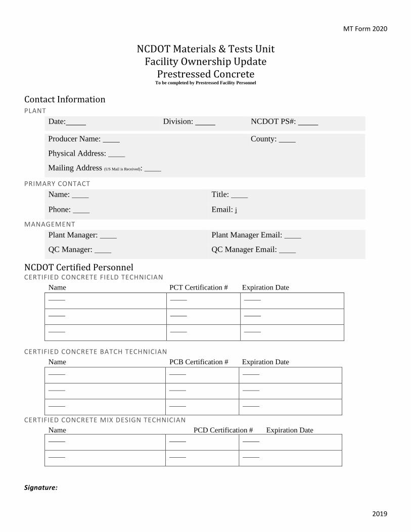
MT Form 2020
2019
NCDOT Materials & Tests Unit Facility Ownership Update
Prestressed Concrete To be completed by Prestressed Facility Personnel
Contact Information PLANT
PRIMARY CONTACT
MANAGEMENT
NCDOT Certified Personnel CERTIFIED CONCRETE FIELD TECHNICIAN
Name PCT Certification # Expiration Date
CERTIFIED CONCRETE BATCH TECHNICIAN Name PCB Certification # Expiration Date
CERTIFIED CONCRETE MIX DESIGN TECHNICIAN Name PCD Certification # Expiration Date
Signature:
Date: Division: NCDOT PS#:
Producer Name: County:
Physical Address:
Mailing Address (US Mail is Received):
Name: Title:
Phone: Email: j
Plant Manager: Plant Manager Email:
QC Manager: QC Manager Email:

MT Form P38
North Carolina Department of Transportation Materials & Tests Unit
Prestressed Concrete Annual Facility Audit Checklist
Date:
Facility Name: Facility State ID: PS
Type of Inspection: 6 month ☐ 12 month ☐ Issued Certificate: Yes ☐ No ☐
Facility Physical Location: Number of Approved Mixers:
Facility Mailing Address: Facility Official & Phone: Facility Batcher & Phone: Facility Manager & Phone:
NCDOT Certified Personnel CERTIFIED CONCRETE BATCH TECHNICIAN
Name PCB Certification # Expiration #
CERTIFIED CONCRETE FIELD TECHNICIAN
Name PCT Certification # Expiration #
CERTIFIED CONCRETE MIX DESIGN TECHNICIAN
Name PCD Certification # Expiration #

MT Form P38
Batching
Type of Plant: ☐Central Mix ☐Transit Mix
Maximum Size of Batch:
General Condition of Plant:
Stockpile Samples, Storage & Handling Does material sample match bill of lading: ☐ Yes ☐ No Does material sample match mix design: ☐ Yes ☐ No
Sample
Material Sample Taken
From HiCAMS #
Date Submitted Comments
Cement
Fly Ash
Fine Aggregate
Must come from approved QC/QA quarry: FA#
Coarse Aggregate
Must come from approved QC/QA quarry: CA#
Admixture
Water Well ☐ City ☐
M&T must sample during audit and send water results back to plant.
Reinforcing Steel
Size of bar
Reinforcing Steel
Size of bar
Reinforcing Steel
Size of bar

MT Form P38
Number of Cement Silos: Capacity:
Type of storage for Aggregates: Number of overhead Bins for Sand:
Sand: Stone:
Methods of Handling Aggregates: Does Ready Mix Plant Stockpile Non-Specification Materials? ☐NO ☐YES
Scales
Type Make of Scale Batch System
Cement ☐Dial ☐Digital
Capacity: Increment:
Aggregate ☐Dial ☐Digital Capacity: Increment:
Water ☐Dial ☐Digital
Capacity: Increment: Storage Tanks:
☐Dial ☐Digital Capacity: Increment:
Scales Calibrated by: Date Calibrated:
Admixtures
Type Product Name Dispensing
Air Entrainment: ☐Automatic: ☐Semi-automatic
Super Plasticizer: ☐Automatic: ☐Semi-automatic
Water Reducer/Retarder: ☐Automatic: ☐Semi-automatic
Corrosion Inhibitor: ☐Automatic: ☐Semi-automatic
Testing Required Moisture Testing Equipment: ☐ Yes ☐ No Test Weights Available: ☐ Yes ☐ No
Heat Source: Water: Yes ☐ No ☐ Capacity Gallon Per Hour:
Cool Source: Water: Yes ☐ No ☐ Capacity Gallon Per Hour:
Other:

MT Form P38 The mixer trucks listed below have been found to comply with the North Carolina Department of Transportation Division of Highways Specifications and may be used to furnish concrete for state work. Trucks that becomes unsatisfactory will be immediately removed from the list.
Truck Number Capacity Cubic Yards Comments
Report Date:
Producers QC Representative:
NCDOT Inspector:
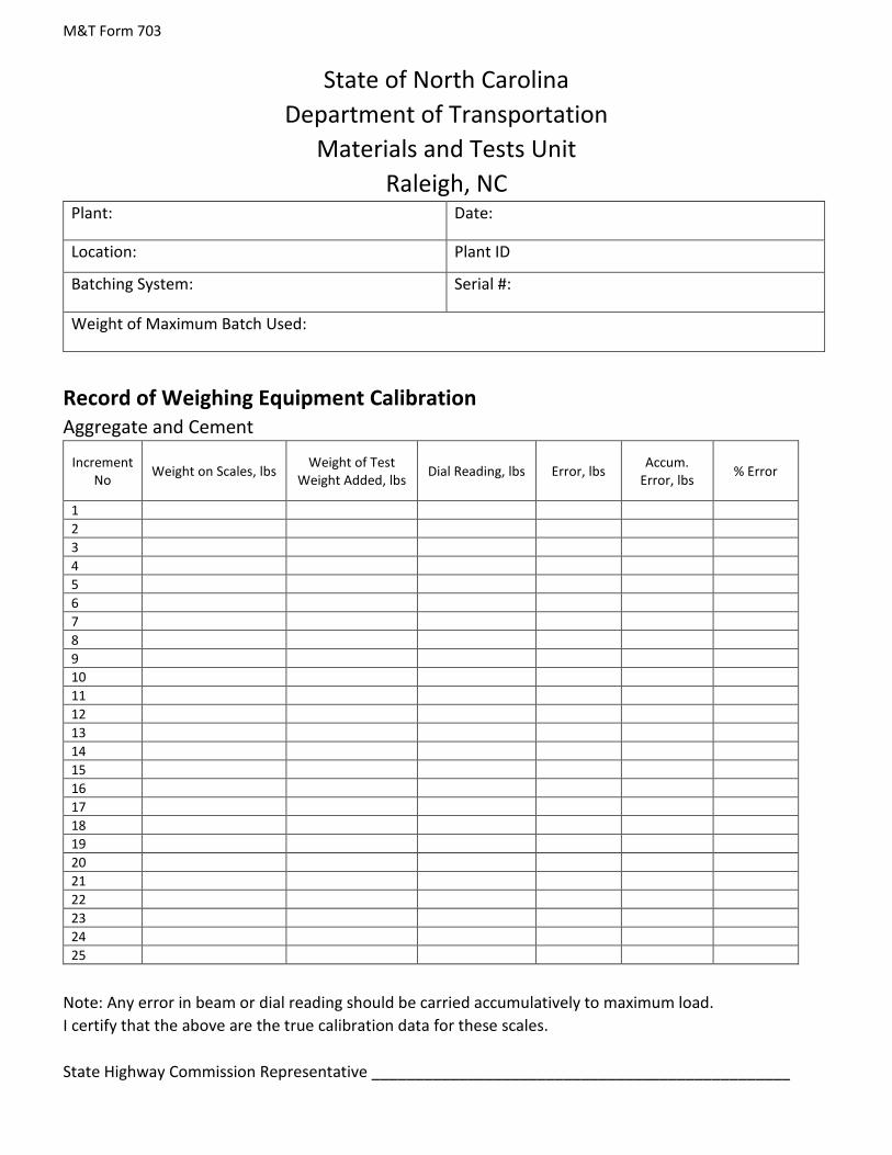
M&T Form 703
State of North Carolina Department of Transportation
Materials and Tests Unit Raleigh, NC
Plant: Date:
Location: Plant ID
Batching System: Serial #:
Weight of Maximum Batch Used:
Record of Weighing Equipment Calibration Aggregate and Cement
Increment No Weight on Scales, lbs Weight of Test
Weight Added, lbs Dial Reading, lbs Error, lbs Accum. Error, lbs % Error
1 2 3 4 5 6 7 8 9 10 11 12 13 14 15 16 17 18 19 20 21 22 23 24 25
Note: Any error in beam or dial reading should be carried accumulatively to maximum load. I certify that the above are the true calibration data for these scales. State Highway Commission Representative ________________________________________________

M&T Form 703
Plant: Date:
Location: Plant ID
Weigh or Meter System: Serial #:
Water
Test No Weight on Scales, lbs Amount of water metered, lbs
Actual Amount of Water
Reading, lbs Error, lbs Accum.
Error, lbs % Error
1 2 3 4 5 6 7 8 9 10 11 12 13 14 15 16 17 18 19 20 21 22 23 24 25
Note: Any error in beam or dial reading should be carried accumulatively to maximum load. I certify that the above are the true calibration data for these scales. State Highway Commission Representative ________________________________________________


Author: Karen H. Goodall Revision #: 1Approved by: Len Sanderson Date Issued: October 1, 2004
Sampling and Inspection at Producer’s Facility – SOP 11B-71
SAFE OPERATING PROCEDURES
Sampling and Inspection at SOP 11B-71Producer’s Facility
Hazard ReviewLifting Crushing Injuries BurnsMoving Equipment Flying Particles Slip, Trip and FallNoise Fumes Cuts
Required Personal Protective Equipment (PPE)Safety Shoes Hard Hat Safety VestSafety Glasses Hearing Protection Respirator
1. Use proper lifting techniques.2. Wear safety shoes or boots at all times. Wear hard hats, safety vests, safety glasses, hearing
protection and breathing protection as required by Personal Protective Equipment policy orproducer’s policy, whichever is more stringent.
3. Review and follow producer’s safety procedures.4. Be aware of moving equipment and moving parts on machinery. Be alert at all times.5. Be aware of uneven and/or slippery surfaces.6. Operate all hand and power tools properly. Be sure all guards and shields are in place.7. Be aware of sharp edges on materials.8. Be aware of hot surfaces associated with welding.9. Avoid work under or adjacent to suspended loads.
Related SOP’sGeneral SOPs .........................................Chapter 10 Welding, Oxy-Acetylene Cutting/ ................11A-40Welding, Arc...............................................11A-39 Hand Tools (Power and Manual) ..................12B-13Roadway Inspection.................................... 11B-69 Borrow Pit, Waste Pit and...............................11B-8
Stockpiling Operations
SPoole
Typewritten Text
Appendix 8.1
SPoole
Typewritten Text

Appendix 8.2
Prestressed Member Discrepancies Prestress Non-Conformance Report (NCR) Policy
Required Procedures for Non-Conformance Members
• In the event the inspector has determined there is a discrepancy with a Prestressed member, the inspector should begin to fill out the applicable NCR form for the member type. The inspector should determine if the discrepancy is a Standard Repair, or does the discrepancy report need to be submitted to SMU? In both cases, the NCR form should to be filled out completely. Under the comments section, give as much information as possible. Explain the discrepancy in detail with measurements. Take several photos of the member from as many angles as possible. Ensure the photos are clear and attach to the NCR. Make sure that the Producers QC personnel reviews and signs the NCR.
• The producer must write a proposed procedure for repairing the non-conformant member. The proposal must be detailed, including ways and means for the repair. A copy must be sent to the M&T inspector who will combine the producer’s proposal with the NCR and photos.
• The inspector sends this “packet” to James Bolden [email protected] (SMU), the Resident Engineer, the NCDOT Regional Supervisor, the Concrete Products Engineer and the producer.
• The Structures Unit will review the NCR and provide a response in a timely manner. • If for any reason you have a time critical situation, contact your NCDOT Regional Supervisor ASAP
and he can assist with expediting a resolution. • See current Standard Repair NCR’S below.
Structures Management Unit Review Comments For questions or comments, contact James L. Bolden, Jr., PE at (919)707–6408 Madonna Rorie, PE at (919)707-6508. 1078-12 Summary 1078-12 VERTICAL CRACKS IN PRESTRESSED CONCRETE GIRDERS BEFORE DETENSIONING This section addresses prestressed concrete members that have vertical casting cracks before strand detensioning. Certain types of these cracks have been determined by the Department to render the girders unacceptable. Unacceptable cracked members are those with 2 or more vertical cracks spaced at a distance less than the member depth (Member Depth=Height of the girder, i.e. 72”, 54”) which extend into the bottom flange. Such members are not serviceable and will be rejected. Members with 2 or more vertical cracks spaced at a distance less than the member depth (Member Depth=Height of the girder, i.e. 72”, 54”) but do not extend into the bottom flange are subject to an engineering assessment. Such members may not be serviceable and may be rejected.

Appendix 8.2
Members with one or more vertical cracks that extend into the bottom flange and are spaced at a distance greater than the member depth (Member Depth=Height of the girder, i.e. 72”, 54”) are subject to an engineering assessment to determine their acceptability. If this engineering assessment is required, submit, at no additional cost to the Department, a proposal for repairing the member and a structural evaluation of the member prepared by an engineer licensed by the State of North Carolina. In the structural evaluation, consider the stresses under full service loads had the member not cracked and the effects of localized loss of prestress at the crack as determined by methods acceptable to the Department. All members, except those defined as unacceptable, which exhibit vertical cracks before detensioning, shall receive a 7 day water cure as directed by the Engineer. The water cure shall begin within 4 hours after detensioning the prestressing strands and shall be at least 3ft beyond the region exhibiting vertical cracks. The Department has the final determination regarding acceptability of any members in question. Note: Prestressed Concrete Members with more than 3 vertical cracks shall require an engineering assessment prior to acceptance by the Department. NCR- Standard Repair Procedures In–plant Repairs Only – For the Following Situations:
o Honeycomb or Void in Web – Prestressed Concrete Girders o Honeycomb or Void in Side – Cored Slabs and Box Beams
**These standard procedures will only be applicable for honeycomb or voids that have the following characteristics:
1. There is no exposed prestressing strand.
2. There may or may not be exposed reinforcing steel.
3. Total height of void shall be less than or equal to 20% of the web depth or 20% of the cored slab/box
beam height.
4. Total length of void shall be less than or equal to 50% of the web depth or 50% of the cored slab/box beam height.
The NCDOT Structures Management Unit recommends that the following standard repair procedures be followed for all girders, cored slabs, and box beams in which honeycomb or voids have been observed in the web:
1. Provide sawcut a minimum of 1” beyond the perimeter of the repair area, to a minimum depth of ½”. 2. Remove all unsound concrete within the repair area. Remove all concrete – unsound and sound– within
the sawcut to a minimum depth of ½”. 3. If more than half the circumference of a reinforcing bar is exposed, remove additional concrete to 1”
behind the bar. This does not apply to prestressed strands. 4. For areas in which no steel is exposed, use adhesively anchored anchors, with a minimum ¼” diameter,
spaced at 6” grid, to provide mechanical bond for repair material. Provide the design concrete cover for studs.
5. Do not damage rebar or strand. 6. Form and place repair material to original shape. 7. If needed, vent or shape repair area to avoid pockets that could trap air.
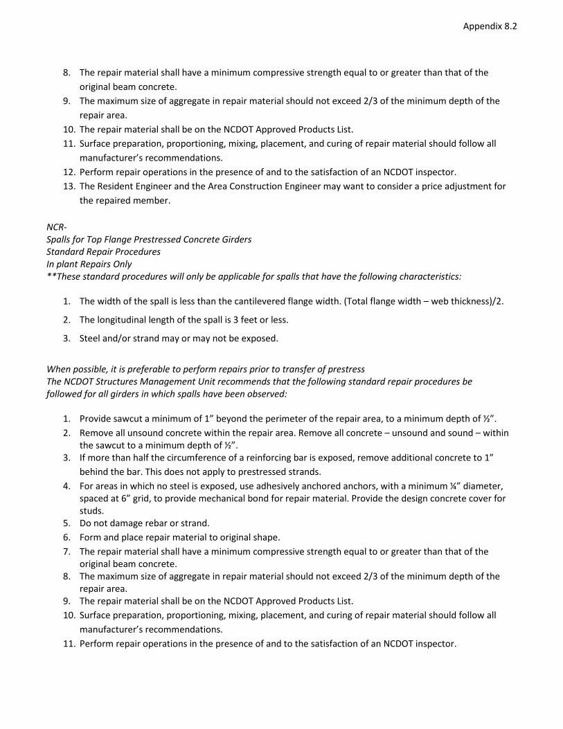
Appendix 8.2
8. The repair material shall have a minimum compressive strength equal to or greater than that of the original beam concrete.
9. The maximum size of aggregate in repair material should not exceed 2/3 of the minimum depth of the repair area.
10. The repair material shall be on the NCDOT Approved Products List. 11. Surface preparation, proportioning, mixing, placement, and curing of repair material should follow all
manufacturer’s recommendations. 12. Perform repair operations in the presence of and to the satisfaction of an NCDOT inspector. 13. The Resident Engineer and the Area Construction Engineer may want to consider a price adjustment for
the repaired member. NCR- Spalls for Top Flange Prestressed Concrete Girders Standard Repair Procedures In plant Repairs Only **These standard procedures will only be applicable for spalls that have the following characteristics:
1. The width of the spall is less than the cantilevered flange width. (Total flange width – web thickness)/2.
2. The longitudinal length of the spall is 3 feet or less.
3. Steel and/or strand may or may not be exposed.
When possible, it is preferable to perform repairs prior to transfer of prestress The NCDOT Structures Management Unit recommends that the following standard repair procedures be followed for all girders in which spalls have been observed:
1. Provide sawcut a minimum of 1” beyond the perimeter of the repair area, to a minimum depth of ½”. 2. Remove all unsound concrete within the repair area. Remove all concrete – unsound and sound – within
the sawcut to a minimum depth of ½”. 3. If more than half the circumference of a reinforcing bar is exposed, remove additional concrete to 1”
behind the bar. This does not apply to prestressed strands. 4. For areas in which no steel is exposed, use adhesively anchored anchors, with a minimum ¼” diameter,
spaced at 6” grid, to provide mechanical bond for repair material. Provide the design concrete cover for studs.
5. Do not damage rebar or strand. 6. Form and place repair material to original shape. 7. The repair material shall have a minimum compressive strength equal to or greater than that of the
original beam concrete. 8. The maximum size of aggregate in repair material should not exceed 2/3 of the minimum depth of the
repair area. 9. The repair material shall be on the NCDOT Approved Products List. 10. Surface preparation, proportioning, mixing, placement, and curing of repair material should follow all
manufacturer’s recommendations. 11. Perform repair operations in the presence of and to the satisfaction of an NCDOT inspector.

Appendix 8.2
12. The Resident Engineer and the Area Construction Engineer may want to consider a price adjustment for the repaired member.
NCR- Longitudinal Cracks Standard Repair Procedures The NCDOT Structures Management Unit recommends that the following standard procedure be followed for all girders, cored slabs, and box beams in which longitudinal cracks have been observed:
1. For crack widths less than or equal to .005”, a seven–day water cure is the only action required. 2. For crack widths greater than .005” and less than .010”, use a silane spray on the cracks, one that is on the
NCDOT Approved Products List. 3. For crack widths equal to or greater than .010”, use an approved epoxy injection procedure. The repair
material shall be on the NCDOT Approved Products List. The procedure shall be performed in the presence of and to the satisfaction of an NCDOT inspector.
If the cracks
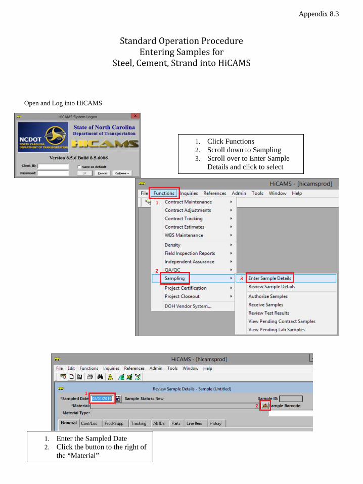
Appendix 8.3
Standard Operation Procedure Entering Samples for
Steel, Cement, Strand into HiCAMS
Open and Log into HiCAMS
1. Click Functions 2. Scroll down to Sampling 3. Scroll over to Enter Sample
Details and click to select
1. Enter the Sampled Date 2. Click the button to the right of
the “Material”

Appendix 8.3 Steel
1. Select the Material Type radio button 2. Enter Reinforcing in Material Field 3. Click Retrieve 4. Select Reinforcing Steel, Plain with UOM as Pounds. Verify English units are being used. 5. Click ok

Appendix 8.3 Steel – General tab entries
1. Enter M&T as Sample Owner 2. Enter Field ID – This is the current year followed by the sample number 3. Enter Verification as the Testing Category 4. Sample Frequency Comments field - Enter the # of pieces. Comments should include- two
30” samples, of each size bar, per heat number. 5. Enter the total pounds of rebar for this heat number as Represented Qty. 6. Enter Prestress in to be used in field 7. Comments- Enter the type of rebar, grade of rebar, heat number and made & melted in USA
Example – type of rebar, #5, grade of rebar, 60, Heat # 53782. This information populates the M&T 913 Form.

Steel – Cont/Loc tab entries 1. Select Plant in the sample from field and enter the plant number, PS#, in the field to the right 2. Enter PS# in the Location Field. It is redundant to what was just entered in sample from

Steel – Prod/Supp tab entries 1. Search by Plant ID Field refers to the producer/supplier of the rebar. Reinforcing Steel begins
with RS. If you know the ID, enter it in the field. 2. If you do not know the RS#, click the icon to the right of Approved Producer/Supplier to search.
Click the applicable producer. If you cannot find the producer, contact M&T lab at 919-329-4000

Steel – Tracking tab entries 1. Sampled By field – select your name or the person who did the sampling 2. Submitted Date field – enter a date 1-2 days after the actual date you are making this entry,
BUT before you think the sample will arrive to the lab. This will allow you to correct any unforeseen errors.
3. Submitted To field – select Central Lab Struct Mtls – Physical. Selection of the wrong lab causes delays. Ensure you have made the correct selection.

Steel – Alt ID tab entries 1. Select Heat as Alternate ID Type 2. Enter the Heat Number as the Alternate ID. The Heat Number is the RS# - 2-digit month, 2 digit
day, 2 digit year, - Heat Number. RSxx-mmddyy-heat.
SAVE YOUR WORK Click the save icon in the top left corner or click FILE in the top left corner and select save. Record the Sample ID on the HiCAMS card and in your log.
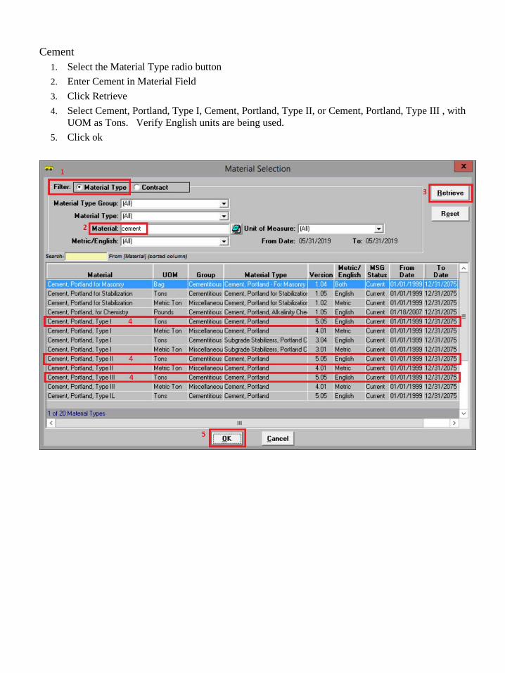
Cement 1. Select the Material Type radio button 2. Enter Cement in Material Field 3. Click Retrieve 4. Select Cement, Portland, Type I, Cement, Portland, Type II, or Cement, Portland, Type III , with
UOM as Tons. Verify English units are being used. 5. Click ok
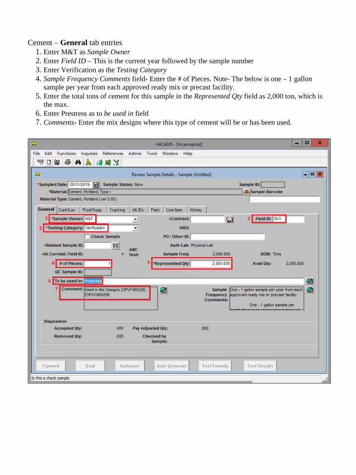
Cement – General tab entries 1. Enter M&T as Sample Owner 2. Enter Field ID – This is the current year followed by the sample number 3. Enter Verification as the Testing Category 4. Sample Frequency Comments field- Enter the # of Pieces. Note- The below is one – 1 gallon
sample per year from each approved ready mix or precast facility. 5. Enter the total tons of cement for this sample in the Represented Qty field as 2,000 ton, which is
the max. 6. Enter Prestress as to be used in field 7. Comments- Enter the mix designs where this type of cement will be or has been used.
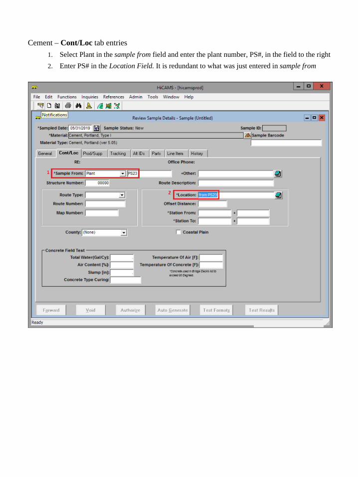
Cement – Cont/Loc tab entries 1. Select Plant in the sample from field and enter the plant number, PS#, in the field to the right 2. Enter PS# in the Location Field. It is redundant to what was just entered in sample from
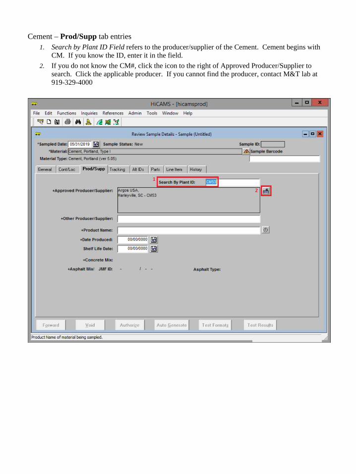
Cement – Prod/Supp tab entries 1. Search by Plant ID Field refers to the producer/supplier of the Cement. Cement begins with
CM. If you know the ID, enter it in the field. 2. If you do not know the CM#, click the icon to the right of Approved Producer/Supplier to
search. Click the applicable producer. If you cannot find the producer, contact M&T lab at 919-329-4000

Cement – Tracking tab entries 1. Sampled By field – select your name or the person who did the sampling 2. Submitted Date field – enter a date 1-2 days after the actual date you are making this entry,
BUT before you think the sample will arrive to the lab. This will allow you to correct any unforeseen errors.
3. Submitted To field – select Central Lab Struct Mtls – Physical. Selection of the wrong lab causes delays. Ensure you have made the correct selection.
SAVE YOUR WORK Click the save icon in the top left corner or click FILE in the top left corner and select save. Record the Sample ID on the HiCAMS card and in your log.

Strand 1. Select the Material Type radio button 2. Enter Strand in Material Field 3. Click Retrieve 4. Select 270 ksi Low Relaxation Prestressing Strand, with UOM as Liner Feet. Verify English
units are being used. *Usually Low Relaxation Prestressing Strand is used but if the contract may require other types of strand to be used – See the contract documents for details
5. Click ok
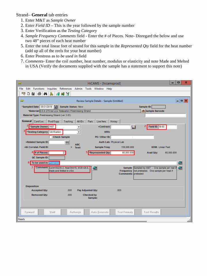
Strand– General tab entries 1. Enter M&T as Sample Owner 2. Enter Field ID – This is the year followed by the sample number 3. Enter Verification as the Testing Category 4. Sample Frequency Comments field - Enter the # of Pieces. Note- Disregard the below and use
two 48” pieces of each heat number 5. Enter the total linear feet of strand for this sample in the Represented Qty field for the heat number
(add up all of the reels for your heat number) 6. Enter Prestress as to be used in field 7. Comments- Enter the coil number, heat number, modulus or elasticity and note Made and Melted
in USA (Verify the documents supplied with the sample has a statement to support this note)

Strand – Cont/Loc tab entries 1. Enter Plant in the sample from field and the plant number, PS#, in the field to the right 2. Enter PS# as the Location. It is redundant to what was just entered in sample from
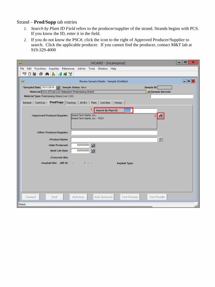
Strand – Prod/Supp tab entries 1. Search by Plant ID Field refers to the producer/supplier of the strand. Strands begins with PCS.
If you know the ID, enter it in the field. 2. If you do not know the PSC#, click the icon to the right of Approved Producer/Supplier to
search. Click the applicable producer. If you cannot find the producer, contact M&T lab at 919-329-4000
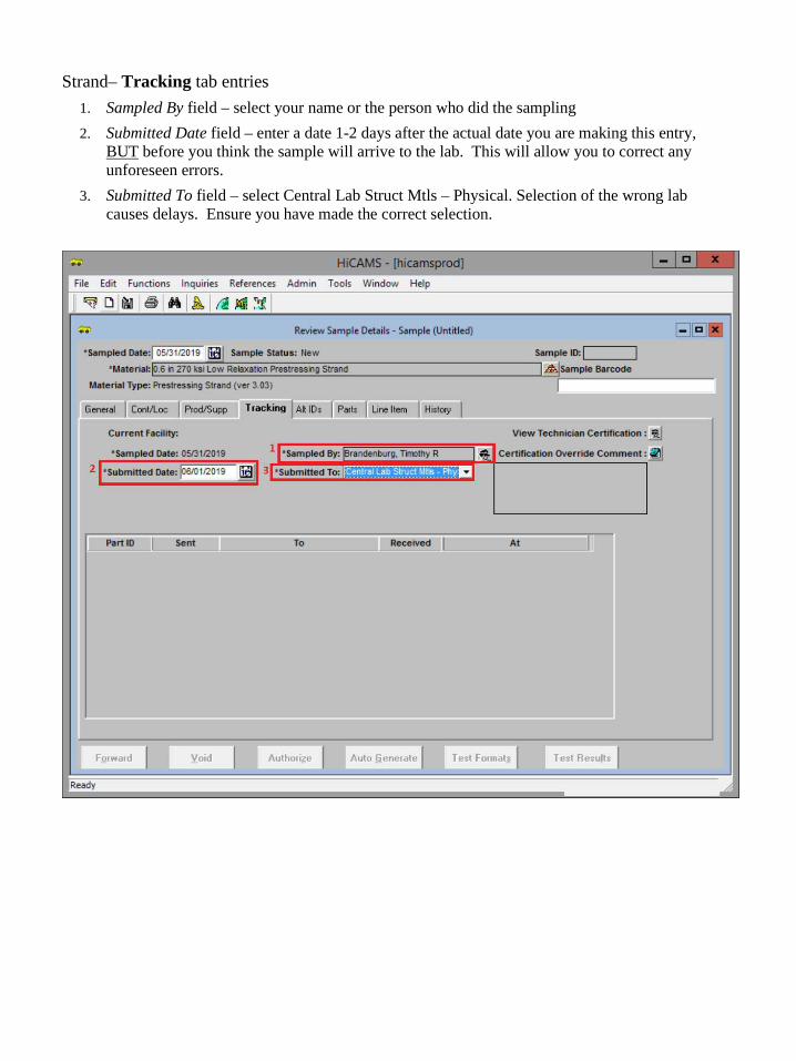
Strand– Tracking tab entries 1. Sampled By field – select your name or the person who did the sampling 2. Submitted Date field – enter a date 1-2 days after the actual date you are making this entry,
BUT before you think the sample will arrive to the lab. This will allow you to correct any unforeseen errors.
3. Submitted To field – select Central Lab Struct Mtls – Physical. Selection of the wrong lab causes delays. Ensure you have made the correct selection.
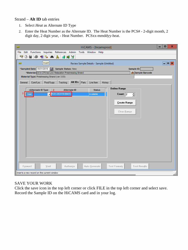
Strand – Alt ID tab entries 1. Select Heat as Alternate ID Type 2. Enter the Heat Number as the Alternate ID. The Heat Number is the PCS# - 2-digit month, 2
digit day, 2 digit year, - Heat Number. PCSxx-mmddyy-heat.
SAVE YOUR WORK Click the save icon in the top left corner or click FILE in the top left corner and select save. Record the Sample ID on the HiCAMS card and in your log.

Appendix 8.4
Quality Assurance Stockpile Material Sampling
• Reinforcing Steel: Once per quarter (every 3 months), take two 30” samples of each size bar, per heat number, regardless of plan quantity excluding epoxy coated rebar. (Random Contracts) Sent to the NCDOT lab for testing. Do not use “TEST BARS “
• Cement: o Verification sample - Cement chemical testing will be sampled monthly (5oz specimen
containers obtained from stockroom) o Acceptance sample - Physical and Chemical testing on cement will be required every six
(Gallon Bag obtained from stockroom) • FlyAsh: One-gallon bag every six months. • Water:
o Once every quarter sample the water for Chloride using chloride strips. Record results. o Once a year sample the water at each producer’s facilities to ensure compliance with
Table 1024-2 Results must be provided to the producer and recorded with the facility audit.
• Prestressing Strand: Two samples of two - 48”in length strands from random heat numbers every month at each producer’s facility.
• Aggerates: NC Aggregate producers supplying aggregate for NC projects, must participate in the NCDOT QA/QC program. Aggerate producers supplying aggregate, but do not haul aggregate into the state of NC will not be required to participate in the NCDOT QC/QA program. Yearly stockpile samples are required.
o 3 full bags of coarse and two full bags of fine aggregate. • Aggregate Gradation: The DOT inspector will be required to review the results from the
producer once a month and retain a copy for our records. • Corrosion Inhibitor: See 1078-4 Portland Cement Concrete (G) Calcium Nitrite Corrosion
Inhibitor. January 2018 Standard Specifications.

Appendix 8.5
RFID / Barcode Tag Location on Prestress Concrete Members
Member Type Location Details
Piles (Square, Cylinder, Sheet) On the top surface, 10 ft from the marked end of the member
Partial-Depth Deck Panels Top surface of the member
Cored Slabs/Box Beams Between the dowel holes on either end of member
I Beams Top surface, 5 ft from the marked end of member
Bulb Tee/ MBT Girders/FIB
Bottom of top flange 5 ft from the marked end of member
Segmental Box Girders Inside Vertical wall of the void
Bent Caps End of Member
Standard Operating Procedure for RFID Scanning
NORTH CAROLINA DEPARTMENT OF TRANSPORTATION
Materials and Tests Unit
Section 7.6
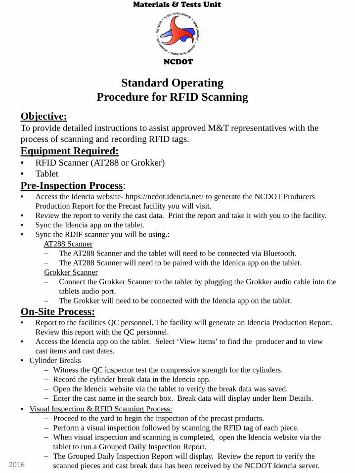
Objective: To provide detailed instructions to assist approved M&T representatives with the process of scanning and recording RFID tags. Equipment Required: • RFID Scanner (AT288 or Grokker) • Tablet Pre-Inspection Process: • Access the Idencia website- https://ncdot.idencia.net/ to generate the NCDOT Producers
Production Report for the Precast facility you will visit. • Review the report to verify the cast data. Print the report and take it with you to the facility. • Sync the Idencia app on the tablet. • Sync the RDIF scanner you will be using.: AT288 Scanner
− The AT288 Scanner and the tablet will need to be connected via Bluetooth. − The AT288 Scanner will need to be paired with the Idenica app on the tablet. Grokker Scanner − Connect the Grokker Scanner to the tablet by plugging the Grokker audio cable into the
tablets audio port. − The Grokker will need to be connected with the Idencia app on the tablet.
Standard Operating Procedure for RFID Scanning
On-Site Process: • Report to the facilities QC personnel. The facility will generate an Idencia Production Report.
Review this report with the QC personnel. • Access the Idencia app on the tablet. Select ‘View Items’ to find the producer and to view
cast items and cast dates. • Cylinder Breaks
− Witness the QC inspector test the compressive strength for the cylinders. − Record the cylinder break data in the Idencia app. − Open the Idencia website via the tablet to verify the break data was saved. − Enter the cast name in the search box. Break data will display under Item Details.
• Visual Inspection & RFID Scanning Process: − Proceed to the yard to begin the inspection of the precast products. − Perform a visual inspection followed by scanning the RFID tag of each piece. − When visual inspection and scanning is completed, open the Idencia website via the
tablet to run a Grouped Daily Inspection Report. − The Grouped Daily Inspection Report will display. Review the report to verify the
scanned pieces and cast break data has been received by the NCDOT Idencia server. 2016

Equipment
Grokker Scanner
AT288 Scanner
Tablet
2016

Prior to arrival at Precast Facility you should access the Idencia* website-https://ncdot.idencia.net/
*Idencia-Applies RFID* Concrete Tracking to infrastructure products from the time of manufacture through end-of-life. The
collection and management of data during production though the build and operating phases.
*RFID-Radio Frequency Identification
Once logged into Idencia, you will generate the NCDOT Producer Production Report for the Precast Facility you will visit. This will give you cast and product details and will alert you to any errors that need to be addressed prior to the inspection. 1. Click “Reports” on the left of the Idencia screen
Pre Inspection Process:
2016
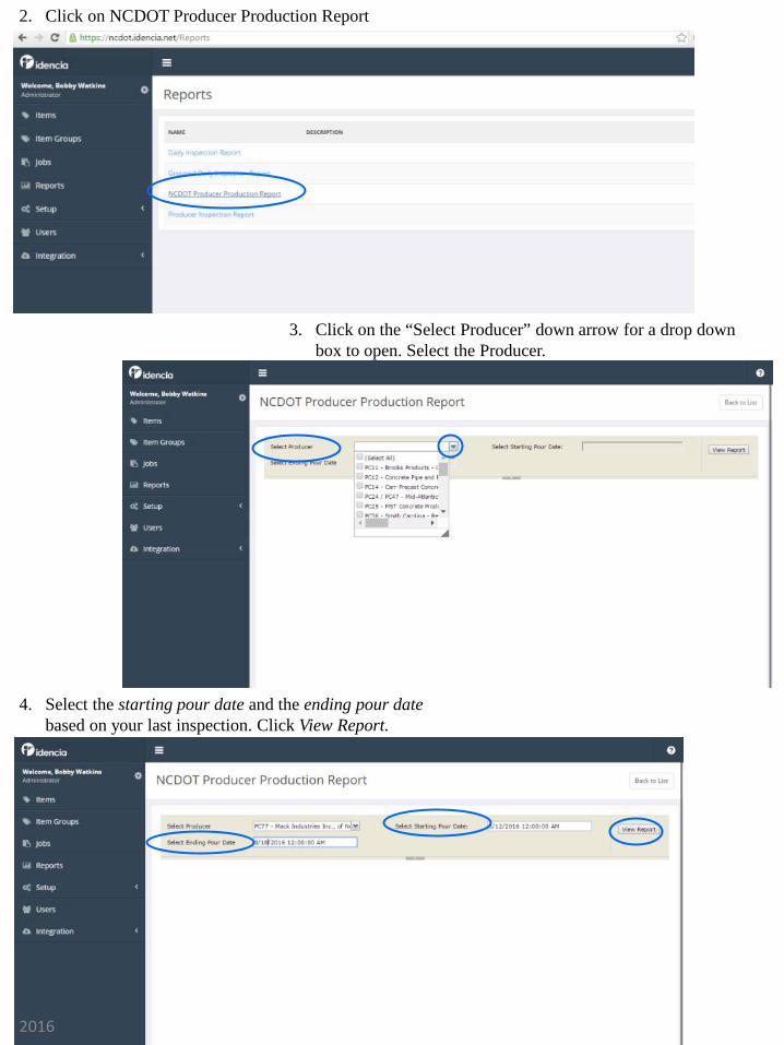
2. Click on NCDOT Producer Production Report
3. Click on the “Select Producer” down arrow for a drop down box to open. Select the Producer.
4. Select the starting pour date and the ending pour date based on your last inspection. Click View Report.
2016

5. The report will display. To view the entire report, you will need to SAVE the report as a PDF. Click the Save icon. Select a location on your computer to save the report.
6. Locate and open the saved report on your computer- • Review the entire report. Verify the Cast row has no missing data in the Air
Content, Slump, Spread, Flow, Concrete Temp, Ambient Temp fields. Also check that the pour date and approved concrete mix design has been entered. Print the report and take it with you to the plant.
2016

Power Key Bluetooth Key
IOS-6C/6B Key
Scan Key
Bluetooth LED
AT288 RFID Scanner must be “Paired” to the tablet prior to scanning Precast items.
• Depress the power Key of the scanner and hold for 3 seconds to turn it on.
• Depress the IOS key, select the 6C setting. The 6C LED light will turn on.
• Depress the Bluetooth Key. The Bluetooth LED light will turn on.
• From your tablet, find and open tablet settings.
• Select Bluetooth from the selection.
• AT288 will appear under devices. This is the RFID Scanner.
• You will enter code 0000, then click OK.
• The RFID scanner is now paired with your tablet.
AT288 Scanner
2016

Connecting the AT288 RDIF scanner to the Idencia app on the tablet
• Open the Idencia app from the tablet home screen
• 1. Select Scan Tag
• 2. Select Connect in the bottom right corner
• 3. Select a device to connect window will open. Select AT288.
• 4. The AT288 scanner is connected and ready to read the RFID tags.
1. 2.
3. 4.
2016

Tablet
Audio cable
Grokker Scanner
• Connect the Grokker Scanner to the tablet by plugging the Grokker audio cable into the tablets audio port.
• Once connected, open the Idencia app on the tablet.
2016

Connecting the Grokker to the Idencia app on the tablet 1. Select the white icon in the right corner of the app. Select settings from the
drop down menu. 2. Settings will open. Select the default scanner U Grok it on the screen. 3. Select scanner box will open. Select U Grok it by touching the open circle.
1.
3.
2.
2016

The Idencia app on the tablet will need to sync to ensure all data is current and up to date
Open the Idencia app from the tablet home screen 1. Select the white icon in the right corner of the app. Select Sync from the drop
down menu. 2. Synchronizing will display at the bottom of the screen. 3. Last sync message will display with the current sync time.
Last sync: Today at 12:00 PM
1. 2.
3.
2016
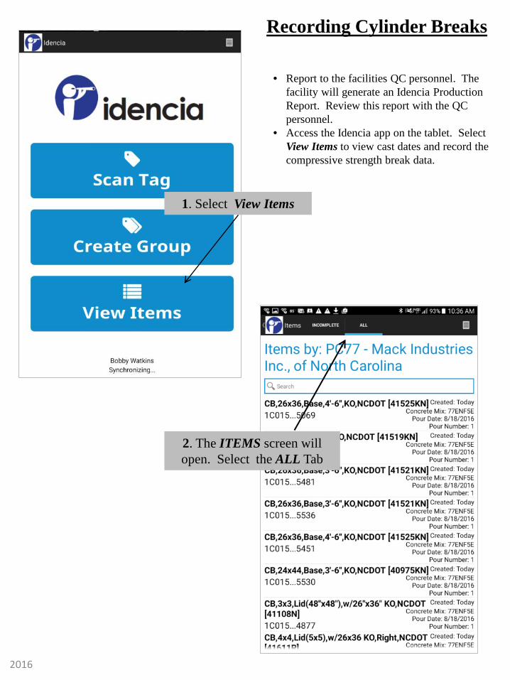
1. Select View Items
2. The ITEMS screen will open. Select the ALL Tab
Recording Cylinder Breaks
• Report to the facilities QC personnel. The facility will generate an Idencia Production Report. Review this report with the QC personnel.
• Access the Idencia app on the tablet. Select View Items to view cast dates and record the compressive strength break data.
2016

3. Select the white icon and click Filter by User
4. Producers will display. Find and select the
appropriate Producer
2016
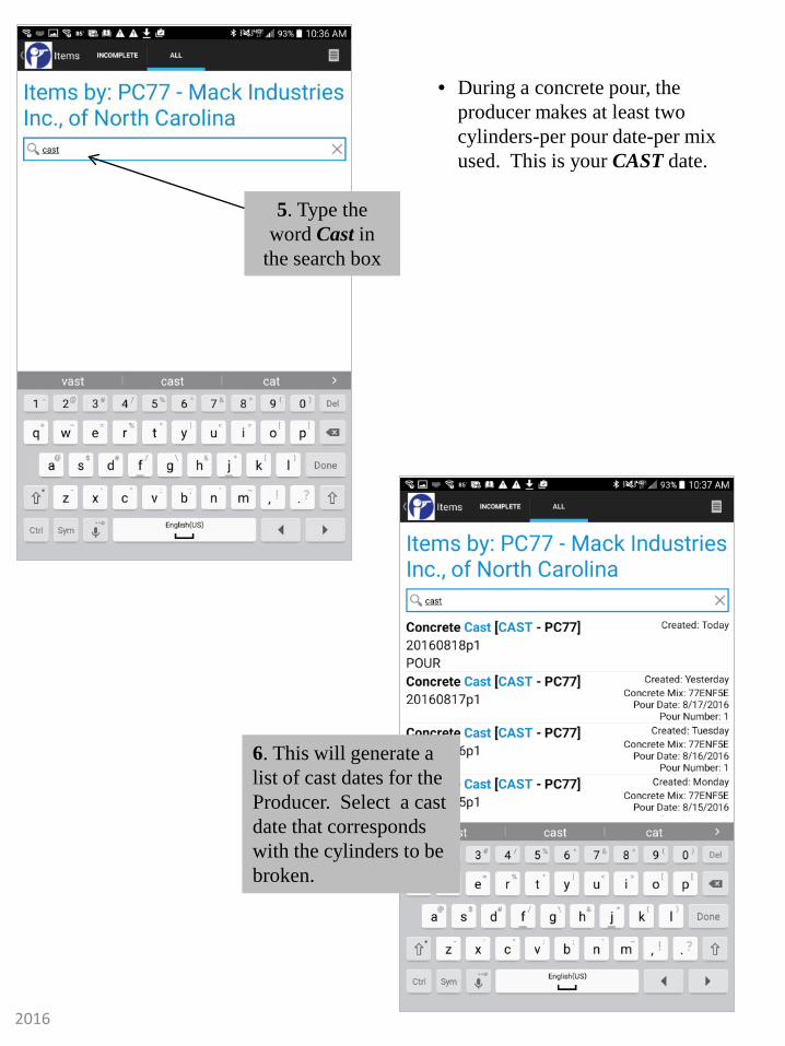
5. Type the word Cast in
the search box
6. This will generate a list of cast dates for the Producer. Select a cast date that corresponds with the cylinders to be broken.
• During a concrete pour, the producer makes at least two cylinders-per pour date-per mix used. This is your CAST date.
2016

7. Select Concrete Test Inspection.
8. The break screen will open in Default Phase. Click within
Break 1 Stress block to enter Break data.
2016

9. Enter 1st cylinder break data and
select ok.
10. Click within Break 2 Stress block to enter
break data.
2016

11. Enter 2nd cylinder break
data and click ok.
12. Select Pass to change
inspection to Fail if needed. Select
date to change the inspection date
then Select Next.
2016

13. Confirm Process Complete message. Then
Select Exit to choose a different cast date. Repeat
steps 6-12 to enter break data.
2016

1. Type the cast name in the search box.
2. The Item Details will display. Scroll through to
verify break data was saved and is accurate. Repeat for
each cast name.
• Open the Idencia Website on your tablet. • You will verity the cast break data entered of each cast
date (The cast date represents the cast name)
Once ALL of the cast break data has been entered, you will access the online version of Idencia to verify the break data was saved.
2016

Items that represent each cast date and breaks will be stacked out in the producers yard.
• Visually inspect each piece
• Scan the RFID tag
2016
Visual Inspection
A visual inspection for precast items shall be conducted to ensure no steel of any kind is exposed. No cracks and minimal to no bug holes, chips, voids or
honeycombing. Please refer to the Precast SOP for additional details. • Proceed to the NCDOT inspection area of the producers yard. • Perform a visual inspection followed by scanning the RFID tag of each piece.
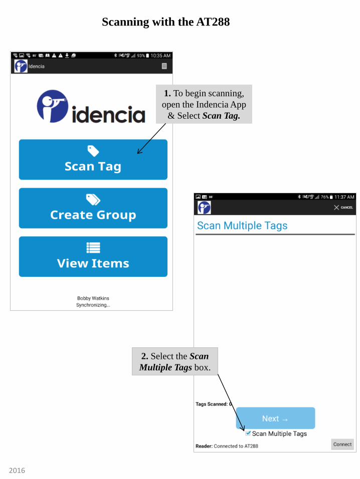
1. To begin scanning, open the Indencia App
& Select Scan Tag.
2. Select the Scan Multiple Tags box.
Scanning with the AT288
2016

4. Continue the visual inspection-scan process for 10-15 pieces. Each item will display on the
screen. Then select Next.
5. You will now choose whether the pieces scanned Pass or Fail the visual inspection by selecting
Product Inspection.
3. To scan the RFID barcode, push the Scan Key on the scanner. When the RDIF tag is scanned, the tag numbers
appear on the tablets screen.
2016

6. Pass is the product inspection default. Select Pass to make a Pass or Fail selection based on the items just scanned. Ensure the NCDOT Inspection Date is correct. Select a date if it needs to be changed. Select Next.
7. Verify message says Process Complete. If you have more items to inspect and scan, select Exit to repeat the scanning process.
2016
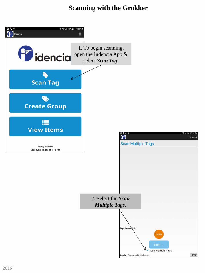
1. To begin scanning, open the Indencia App &
select Scan Tag.
2. Select the Scan Multiple Tags.
Scanning with the Grokker
2016

4. Continue the visual inspection-scan process for 10-15 pieces. Each piece will display on the
screen. Then select Next.
*Selecting Next will let you Select New Process. You will need to record the
Product Inspection results as Pass or Fail.
5. You will now choose whether the pieces scanned Pass or Fail the visual inspection
by selecting Product Inspection.
3. To scan the RFID barcode, push the Scan Key on the tablet screen. When the RDIF tag is scanned, the tag numbers appear on the tablets
screen.
2016

6. Pass is the product inspection default. Select Pass to make a Pass or Fail selection based on the items just scanned. Ensure the NCDOT Inspection Date is correct. Select
a date if it needs to be changed. Select Next.
7. Verify message says Process Complete. If you have more pieces to inspect and scan, select Exit to repeat the scanning process.
2016

Verify the pieces scanned are being recorded in Idencia
• You will need to verify the pieces are being recorded in Idencia once you finish scanning by running a Grouped Daily Inspection Report
• To display the Grouped Daily Inspection Report, open the online version of Idencia. • Click “Reports” on the left of the Idencia screen • Click on Grouped Daily Inspection Report
2016

• Click on the Select Inspector down arrow for a drop down box to open. Select your name.
• Click Select Inspection Date down arrow for a drop down box to open. Select the Inspection Date.
2016

• Click View Reports
• The report will display and you can quickly verify the scans are being recorded by looking at Total Product Inspections. This number will let you know how many pieces you have inspected.
2016

• At the end of your inspection, return to the producers office and compare the Grouped Daily Inspection Report with the NCDOT Producers Production Report. The producer representative used the NCDOT Producers Production Report to manually check off pieces as you scanned the RFID tag. If the total and pieces match on both reports, your inspection is complete. If the totals do not match, check the Grouped Daily Inspection Report for duplicates and omissions. It may be necessary to return to the yard and re-scan some pieces. Resolve any discrepancies prior to leaving producers facility in order to expedite the FIR process.
2016


![Operating Procedures 1 G2 - OPERATING PROCEDURES [6 Exam Questions - 6 Groups] G2APhone operating procedures; USB/LSB utilization conventions; procedural.](https://static.fdocuments.us/doc/165x107/56649e4d5503460f94b4351a/operating-procedures-1-g2-operating-procedures-6-exam-questions-6-groups.jpg)