STANDARD APPLICATION BOARD 2 USER MANUAL - … · · 2016-05-23(separate from LPC Program Flash)...
22
USER MANUAL Ɩ EM7180SFP Copyright 2016, EM Microelectronic-Marin SA 7180SFP-MN02, Version 1.0, 20-May-16 1 www.emmicroelectronic.com 420005-A01, 3.0 STANDARD APPLICATION BOARD 2 USER MANUAL TABLE OF CONTENTS 1 INTRODUCTION .............................................................................................................................................................. 2 1.1 SCOPE OF THE DOCUMENT ............................................................................................................................................ 2 1.2 REFERENCES ................................................................................................................................................................ 2 1.3 OVERVIEW .................................................................................................................................................................. 3 2 SAB2 FIRMWARE APPLICATIONS .................................................................................................................................. 10 2.1 SENSOR-DRIVEN MOUSE WITH BLE & USB (SENSORMOUSEBLEUSB) ................................................................................ 10 2.2 SENSOR-DRIVEN JOYSTICK WITH USB INTERFACE (SENSORJOYSTICKUSB) .............................................................................. 12 2.3 USB HID INTERFACE TO SAB2 I2C MASTER (I2CHID) ..................................................................................................... 13 2.4 SENSOR READ TEST APPLICATION (SENSORREADTEST) ....................................................................................................... 14 2.5 SENSOR SIMPLE EXAMPLE APPLICATION (SENSORSIMPLEEXAMPLE)...................................................................................... 15 2.6 HID SENSOR CLASS-COMPLIANT APPLICATION (SENSORHID) ............................................................................................. 16 2.7 SAB2 CONFIGURATION UTILITY (SAB2CONFIGUTIL) ........................................................................................................ 19 3 APPENDIX A – QUICK START GUIDE TO BUILDING THE FIRMWARE............................................................................... 22 EM MICROELECTRONIC - MARIN SA
Transcript of STANDARD APPLICATION BOARD 2 USER MANUAL - … · · 2016-05-23(separate from LPC Program Flash)...

USER MANUAL Ɩ EM7180SFP
Copyright 2016, EM Microelectronic-Marin SA 7180SFP-MN02, Version 1.0, 20-May-16
1 www.emmicroelectronic.com
420005-A01, 3.0
STANDARD APPLICATION BOARD 2 USER MANUAL
TABLE OF CONTENTS
1 INTRODUCTION .............................................................................................................................................................. 2
1.1 SCOPE OF THE DOCUMENT ............................................................................................................................................ 2 1.2 REFERENCES ................................................................................................................................................................ 2 1.3 OVERVIEW .................................................................................................................................................................. 3
2 SAB2 FIRMWARE APPLICATIONS .................................................................................................................................. 10
2.1 SENSOR-DRIVEN MOUSE WITH BLE & USB (SENSORMOUSEBLEUSB) ................................................................................ 10 2.2 SENSOR-DRIVEN JOYSTICK WITH USB INTERFACE (SENSORJOYSTICKUSB) .............................................................................. 12 2.3 USB HID INTERFACE TO SAB2 I2C MASTER (I2CHID) ..................................................................................................... 13 2.4 SENSOR READ TEST APPLICATION (SENSORREADTEST) ....................................................................................................... 14 2.5 SENSOR SIMPLE EXAMPLE APPLICATION (SENSORSIMPLEEXAMPLE) ...................................................................................... 15 2.6 HID SENSOR CLASS-COMPLIANT APPLICATION (SENSORHID) ............................................................................................. 16 2.7 SAB2 CONFIGURATION UTILITY (SAB2CONFIGUTIL) ........................................................................................................ 19
3 APPENDIX A – QUICK START GUIDE TO BUILDING THE FIRMWARE ............................................................................... 22
EM MICROELECTRONIC - MARIN SA

USER MANUAL Ɩ EM7180SFP
Copyright 2016, EM Microelectronic-Marin SA 7180SFP-MN02, Version 1.0, 20-May-16
2 www.emmicroelectronic.com
420005-A01, 3.0
1 INTRODUCTION
1.1 SCOPE OF THE DOCUMENT
This document describes how to use the Standard Application Board Rev 2 (aka SAB2) hosting an EM7180SFP Sensor Fusion Platform module. Firmware applications and interfacing methods will be discussed.
Figure 1 - The SENtral SAB2 kit
1.2 REFERENCES
[1] EM7180SFP Data Sheet
[2] CMM-9301-V4.4 BLE HCI module Data Sheet
[3] LPC15xx User Manual, NXP Document Number UM10736
[4] LPC15xx Product Data Sheet
[5] EM Monitor User Guide

USER MANUAL Ɩ EM7180SFP
Copyright 2016, EM Microelectronic-Marin SA 7180SFP-MN02, Version 1.0, 20-May-16
3 www.emmicroelectronic.com
420005-A01, 3.0
1.3 OVERVIEW
The SAB2 provides an ideal prototyping platform for wireless motion-sensing applications.
The major functional components of the SAB2 are illustrated in the following block-diagram:
EM7180SFPModule
This hardware platform, combined with example firmware applications, gives developers a head-start on product development.

USER MANUAL Ɩ EM7180SFP
Copyright 2016, EM Microelectronic-Marin SA 7180SFP-MN02, Version 1.0, 20-May-16
4 www.emmicroelectronic.com
420005-A01, 3.0
The SAB2 is further illustrated in the annotated photo below:
1.3.1 EM7180SFP Sensor Fusion Platform Module (SFP)
The EM7180SFP is an electronic module that makes it easy to quickly integrate, optimize and operate multiple sensors on mobile consumer electronics devices.
1.3.2 CMM-9301 Bluetooth Low Energy Radio Module
The CMM-9301-V4.4 module is a miniaturized BLE controller module based on EM Microelectronic's low power fully integrated single-chip Bluetooth Low Energy (BLE) Controller EM9301. The module is highly optimized for Bluetooth 4.0 Single Mode (Bluetooth Low Energy) link application requiring ultra-low power consumption and short time-to-market. It offers a plug and play solution for any BLE application up to the link layer, without any additional hardware nor RF layout. Built in with a folded dipole PCB antenna, this small sized, low cost module provides an ideal solution to the new BLE technology.
Figure 2 - CMM-9301 Bluetooth Low Energy Module
See reference [2] for more information on the CMM-9301.
General Purpose
Pushbuttons (4) UART Serial I/F JTAG I/F for Debug
Support
ISP Pushbutton
Reset Pushbutton
EM7180 SFP Module General Purpose
LEDs (4) CMM-9301 Bluetooth
Low Energy HCI Module
Power and I2C I/F
connector
USB I/F
(mini B connector)
LPC1549
Processor
Data Flash Memory
(separate from LPC
Program Flash)

USER MANUAL Ɩ EM7180SFP
Copyright 2016, EM Microelectronic-Marin SA 7180SFP-MN02, Version 1.0, 20-May-16
5 www.emmicroelectronic.com
420005-A01, 3.0
1.3.3 NXP LPC1549 Processor
The SAB2 is based on the NXP LPC1549, a USB-capable ARM Cortex M3 processor designed for embedded applications. It features a rich peripheral set with very low power consumption. Other key attributes are:
Ɩ ARM Cortex-M3 processor (version r2p1), running at 72 MHz.
Ɩ Built-in Nested Vectored Interrupt Controller (NVIC).
Ɩ System tick timer.
Ɩ Serial Wire Debug (SWD) with four breakpoints and two watchpoints.
Ɩ Single-cycle multiplier supported.
Ɩ Memory Protection Unit (MPU) included.
Ɩ On-Chip Memory:
o 256 kB Flash Program Memory
o 36 kB SRAM
o 4 kB EEPROM
Ɩ ROM API support:
o Boot loader with boot options from flash or external source
o Peripheral drivers (USB, ADC, SPI, USART, I2C, …)
Ɩ 12 bit Analog-to-digital Converters
See references [3] and [4] for more information on the LPC1549 processor.
1.3.4 Push Buttons
The SAB2 has four general purpose push buttons which can be used in application-dependent ways. See Section 2 “SAB2 FW Applications” for a description of button usage in the applications provided in the development kit.
For customer-developed applications, the state of the buttons can be sensed by checking the input of the GPIO bits in accordance with the following table:
Button Label on PCB GPIO Port and Bit BoardLib API
SW0 Port 0, bit 11 Board_Button_GetState(BOARD_BUTTON_0)
SW1 Port 0, bit 12 Board_Button_GetState(BOARD_BUTTON_1)
SW2 Port 0, bit 13 Board_Button_GetState(BOARD_BUTTON_2)
SW3 Port 0, bit 14 Board_Button_GetState(BOARD_BUTTON_3)
The following figure (extracted from the schematic) illustrates the button circuitry:

USER MANUAL Ɩ EM7180SFP
Copyright 2016, EM Microelectronic-Marin SA 7180SFP-MN02, Version 1.0, 20-May-16
6 www.emmicroelectronic.com
420005-A01, 3.0
1.3.5 LEDs
The SAB2 has four general purpose LED indicators which can be used in application-dependent ways. See Section 2 “SAB2 FW Applications” for a description of LED usage in the applications provided in the development kit.
For customer-developed applications, the LED indicators can be turned on and off via GPIO bits in accordance with the following table:
LED Label on PCB GPIO Port and Bit BoardLib API (where state=true for On and false for Off)
DS0 Port 0, bit 0 Board_LED_Set(LED_DS0, state)
DS1 Port 0, bit 1 Board_LED_Set(LED_DS1, state)
DS2 Port 0, bit 2 Board_LED_Set(LED_DS2, state)
DS3 Port 0, bit 3 Board_LED_Set(LED_DS3, state)
1.3.6 Serial Communication Port
The SAB2 provides a serial communication port that is used by many of the applications. It is recommended to connect the port to a terminal emulator on a PC using the Acroname S27 USB Serial Converter. Here is a link to the product page:
https://acroname.com/products/USB-SERIAL-CONVERTER?sku=S27-USB-SERIAL
The recommended terminal emulator for a PC is “PuTTY”. Here is a link to the product page:
http://www.chiark.greenend.org.uk/~sgtatham/putty/
The following illustrates typical PuTTY settings for use with the SAB2:

USER MANUAL Ɩ EM7180SFP
Copyright 2016, EM Microelectronic-Marin SA 7180SFP-MN02, Version 1.0, 20-May-16
7 www.emmicroelectronic.com
420005-A01, 3.0
Illustrated below is the SAB2 with an S27 USB Serial Converter attached:
Serial Converter
USB Cable to PC
USB Cable to PC
SAB2 Board
1.3.7 SAB2 Power Options
The SAB2 can be powered from either of two interfaces:
Ɩ USB Port
Ɩ GND/VCC pins of the P4 Connector
If the SAB2 is connected to a PC via the USB, then the power problem is solved. If the SAB2 is to be used in a wireless configuration, then a mobile power source is needed, and here are two options:
1.3.7.1 Powered via USB Battery Pack
A variety of third-party USB battery packs are available. The following photo illustrates use with the Anker Astro Mini, Model A2205:
Short USB Cable
Anker Astro Mini Battery Pack
Resistor accross
GND/VCC to
avoid auto-
shutoff
One consideration in choosing a USB battery pack is the current threshold for auto-shutoff. Many, including the Anker unit shown, will automatically shut off if the current draw is too low. The typical current draw of the SAB2 is below the shut-off threshold. A work-around is to install a 200 ohm resistor across the GND/VCC pins of P4.

USER MANUAL Ɩ EM7180SFP
Copyright 2016, EM Microelectronic-Marin SA 7180SFP-MN02, Version 1.0, 20-May-16
8 www.emmicroelectronic.com
420005-A01, 3.0
1.3.7.2 Powered via Battery Daughter-board
The P69398 Battery Board is designed to attach directly to the SAB2 P4 connector and sit on the top of the board. This board is not part of the standard SAB2 package. The following photos illustrate the Battery Board:
Figure 3- Battery Board
Figure 4 Battery Board attached to SAB2 P4 connector

USER MANUAL Ɩ EM7180SFP
Copyright 2016, EM Microelectronic-Marin SA 7180SFP-MN02, Version 1.0, 20-May-16
9 www.emmicroelectronic.com
420005-A01, 3.0
1.3.8 SAB2 Firmware
A variety of firmware applications for the SAB2 have been provided to give the user a head start in prototyping their own applications. The available applications are described in Section 2.
Building the firmware applications from the source code is also supported. See Appendix A – Quick Start Guide to building the Firmware.
Firmware can be installed on the SAB2 using the “In System Programming” feature described in the next section. Once the firmware is installed via this method, pushing the RESET button will automatically start the loaded application:
1.3.8.1 In-System-Programming (ISP) Mode
When reset with the ISP button depressed, the ROM bootloader runs, which instantiates a USB mass storage device on the attached host; the drive is named “CRP DISABLD”. This storage device contains one file, “firmware.bin”. Delete this file and replace it with another
.bin file to store new firmware in the LPC1549. You do not need to rename the file to “firmware.bin” first. Here are the steps:
1. Connect the SAB2 to a PC with a USB cable 2. Hold down both the Reset and ISP buttons 3. While still holding the ISP button, release the Reset button 4. A USB mass storage device named “CRP_DISABLD” will pop up 5. Release the ISP button 6. Delete firmware.bin from the USB mass storage device 7. Copy the new application firmware to the USB mass storage device 8. Press and release the reset button 9. The SAB2 is now running the new application firmware
NOTE: steps 1 and 2 are equivalent to holding down the ISP button while plugging in the USB cable.

USER MANUAL Ɩ EM7180SFP
Copyright 2016, EM Microelectronic-Marin SA 7180SFP-MN02, Version 1.0, 20-May-16
10 www.emmicroelectronic.com
420005-A01, 3.0
2 SAB2 FIRMWARE APPLICATIONS
The following binary applications are provided for the SAB2 platform:
Binary File Name Description
I2CHID.bin USB HID interface to the I2C master on the SAB2 (providing direct access to the EM7180 SFP module)
SensorMouseBLEUSB.bin Sensor-driven mouse application supporting wireless Bluetooth (BLE) and USB HID interfaces
SensorJoystickUSB.bin Sensor-driven joystick application supporting USB HID interface
SensorReadTest.bin Example application that reads a collection of sensors at 200 Hz with summary statistics printed on the serial port
SensorSimpleExample.bin Simple example of an application that reads accelerometer data from the EM718x SFP module at 10 Hz
SensorHID.bin An application that provides sensor data compliant with the USB HID Sensor Class
SAB2ConfigUtil.bin Utility application that provides a menu-driven user interface to perform various board configuration functions
These applications are described in more detail in the following sections.
2.1 SENSOR-DRIVEN MOUSE WITH BLE & USB (SENSORMOUSEBLEUSB)
This application provides an EM7180SFP sensor-driven mouse pointer which will interface to a variety of devices via standard USB mouse HID reports and BLE mouse HID reports. No special driver is needed for most platforms.
The mouse report descriptors have been modified from the normal XY relative motion format to XY absolute motion so the orientation of the board can be used to indicate a pointing direction (suitable for game input). The X coordinate is controlled by roll, and Y by pitch. In this way, holding the board in the horizontal plane maps the mouse pointer to the middle of the screen.
Selection of the Gyroscope is an exception to the above rule. In that case, yaw (i.e. rotation in the horizontal plan) is used for the X dimension and pitch (i.e. rotation perpendicular to the board) drives the Y dimension. The orientation of the board at initialization is taken as the neutral position pointing to the middle of screen (in the horizontal dimension).
Drift may occur, which can be compensated for by moving the mouse pointer beyond the left or the right edge, which will essentially shift the origin by the amount of overshoot beyond the edge.
At power-up the SAB2 buttons select the sensor or initiate a special mode to serve the USB Flash Disk:
Button Sensor Selected
None Rotation Vector (Quaternion)
SW0 Gyroscope
SW1 Accelerometer
SW2 Accelerometer with more smoothing
After initialization, the mouse buttons have the following functions:
Button Button Function
SW0 Right mouse button
SW1 Enable/disable USB mouse output (off by default)
SW2 Enable/disable Bluetooth (BLE) mouse output (on by default)
SW3 Left mouse button

USER MANUAL Ɩ EM7180SFP
Copyright 2016, EM Microelectronic-Marin SA 7180SFP-MN02, Version 1.0, 20-May-16
11 www.emmicroelectronic.com
420005-A01, 3.0
The current status is shown by the LEDs:
LED Status Indication
DS0 (green) BLE Link Status:
Off – not paired
Blink – pairing
On – paired
DS1 (orange) On if BLE mouse output is enabled
DS2 (red) On if USB mouse output is enabled (toggled by SW1)
DS3 (yellow) Blinks at 1 Hz during normal operation; blinking stops on fault
Error and status information is logged to the serial port (which can safely be left unconnected if not of interest). After initialization is complete, nothing further is logged to the serial port unless an error occurs.
For Bluetooth use, pairing must be initiated by the user on the host device/PC. The SAB2 will identify itself as “SENtral SAB2”. Pairing is automatic on the SAB2 – if it is not paired it will attempt to pair. The method of pairing on a host device varies by the device, of course, but here is a typical screen for a Windows 8 host PC:
Sometimes persistent pairing is difficult to achieve. The following steps are recommended to establish the initial pairing:
Ɩ Start the Manage Bluetooth Devices screen on the PC
Ɩ Apply power to the SAB2
Ɩ Observe the SENtral SAB2 is Ready to pair on the Manage Bluetooth Devices screen
Ɩ Select Pair
Ɩ Observe the device state changes to Connected on the PC screen
Ɩ Observe the mouse pointer is now controlled by the SAB2 geometry
Ɩ Select the SENtral SAB2 device on the PC screen and select Remove device
Ɩ Remove power from the SAB2
Ɩ Wait for the PC to remove the SENtral SAB2 device from the list of devices
Ɩ Apply power to the SAB2
Ɩ Once the SENtral SAB2 device appears on the PC screen, select it and then select Pair
Ɩ Observe the device state changes to Connected on the PC screen
Ɩ Observe the mouse pointer is now controlled by the SAB2 geometry
Ɩ The SAB2 pairing to the PC is now persistent, and cycling power or resetting the board will result in automatic re-connection with the PC

USER MANUAL Ɩ EM7180SFP
Copyright 2016, EM Microelectronic-Marin SA 7180SFP-MN02, Version 1.0, 20-May-16
12 www.emmicroelectronic.com
420005-A01, 3.0
2.2 SENSOR-DRIVEN JOYSTICK WITH USB INTERFACE (SENSORJOYSTICKUSB)
This application provides an EM7180SFP sensor-driven joystick pointer which will interface to a variety of devices via standard USB mouse/joystick HID reports. No special driver is needed for most platforms. The behaviour of this app is very similar to the BLE sensor mouse application (SensorMouseBLEUSB) with the following differences:
Ɩ No Bluetooth (BLE) support
Ɩ The USB reports are declared as GENERIC_JOYSTICK reports (which will generally not interfere with desktop mouse functions)
The mouse report descriptors have been modified from the normal XY relative motion format to XY absolute motion so the orientation of the board can be used to indicate a pointing direction (suitable for game input). The X coordinate is controlled by roll, and the Y coordinate by pitch. In this way, holding the board in the horizontal plane maps the joystick pointer to the middle of the screen.
Selection of the Gyroscope is an exception to the above rule. In that case, yaw (i.e. rotation in the horizontal plan) is used for the X dimension and pitch (i.e. rotation perpendicular to the board) drives the Y dimension. The orientation of the board at initialization is taken as the neutral position pointing to the middle of screen (in the horizontal dimension).
Drift may occur, which can be compensated for by moving the mouse pointer beyond the left or the right edge, which will essentially shift the origin by the amount of overshoot beyond the edge.
At power-up the SAB2 buttons select the sensor:
Button Sensor Selected
None Rotation Vector (Quaternion)
SW0 Gyroscope
SW1 Accelerometer
SW2 Accelerometer with more smoothing
SW3 Unused
After initialization, the mouse buttons have the following functions:
Button Button Function
SW0 Right mouse button
SW1 Enable/disable USB mouse output (on by default)
SW2 Unused
SW3 Left mouse button
The current status is shown by the LEDs:
LED Status Indication
DS0 (green) Unused
DS1 (orange) Unused
DS2 (red) On if USB joystick output is enabled (toggled by SW1)
DS3 (yellow) Blinks at 1 Hz during normal operation; blinking stops on fault
Error and status information is logged to the serial port (which can safely be left unconnected if not of interest). After initialization is complete, nothing further is logged to the serial port unless an error occurs.

USER MANUAL Ɩ EM7180SFP
Copyright 2016, EM Microelectronic-Marin SA 7180SFP-MN02, Version 1.0, 20-May-16
13 www.emmicroelectronic.com
420005-A01, 3.0
2.3 USB HID INTERFACE TO SAB2 I2C MASTER (I2CHID)
This application provides a USB HID interface which can be used to perform I2C read/write operations to the EM7180SFP module via a PC or other host that supports a USB HID interface. It is compatible with PC applications which use the EM718x Host Application Toolkit to manage the communications to the SFP.
No special driver is needed for most platforms.
The LEDs report current status:
LED Status Indication
DS0 (green) Not used
DS1 (orange) Indicates USB activity
DS2 (red) Indicates SFP module “data ready”
DS3 (yellow) Blinks at 1 Hz during normal operation; blinking stops on fault
On startup, a banner will be sent out the UART port identifying the application and version. To maintain maximum performance, no output is provided during normal operation.
HID Feature Reports to set and get parameters that control device behaviour are supported. These are the behaviours’ that can be controlled/monitored in this way:
Ɩ I2C bit rate
Ɩ I2C timeout duration
Ɩ Enable/Disable power consumption measurements of the EM7180SFP
Ɩ Read power consumption measurements of the EM7180SFP
Details on the programming of the I2CHID feature report is out of the scope of this document. The interested user is referred to the I2CHID_FEATURE_REPORT structure defined in the source file app_i2chid_report_structs.h, which can be found in the toolkit “src” area.
Once this application is loaded into the SAB2, it is ready to communicate with an application running on a host PC that knows how to talk the proprietary protocol. The “emmonitor.exe” tool is one such application. It is located in the “bin” folder of the EM718x Host Application Toolkit installation. See the “EM Monitor User Guide” for usage information. The following figure illustrates typical use of the tool:

USER MANUAL Ɩ EM7180SFP
Copyright 2016, EM Microelectronic-Marin SA 7180SFP-MN02, Version 1.0, 20-May-16
14 www.emmicroelectronic.com
420005-A01, 3.0
Another application provided in the toolkit is the “accel-samples.exe” tool. It is a command line tool which samples the accelerometer and prints the samples in both raw and scaled format. Here is an example of a few lines of output:
accel: raw: 19, -159, 1955 scaled: 0.08,-0.70, 8.59 timestamp: 750375 us rate: 130.62 Hz
accel: raw: 23, -163, 1939 scaled: 0.10,-0.72, 8.52 timestamp: 758031 us rate: 130.07 Hz
accel: raw: 23, -163, 1939 scaled: 0.10,-0.72, 8.52 timestamp: 758031 us rate: 130.62 Hz
accel: raw: 23, -159, 1935 scaled: 0.10,-0.70, 8.50 timestamp: 765687 us rate: 130.62 Hz
accel: raw: 23, -163, 1935 scaled: 0.10,-0.72, 8.50 timestamp: 773375 us rate: 130.62 Hz
accel: raw: 23, -163, 1959 scaled: 0.10,-0.72, 8.61 timestamp: 781031 us rate: 130.07 Hz
accel: raw: 27, -159, 1947 scaled: 0.12,-0.70, 8.56 timestamp: 788687 us rate: 130.62 Hz
2.4 SENSOR READ TEST APPLICATION (SENSORREADTEST)
This application is provided as an example of the programming of the EM7180SFP module using the services of the EM718x Host Application Toolkit. The intent of the application is to read a collection of measurements at a rate that would be typical for a hand-held game controller (100 - 200 Hz).
For the user wanting to learn how to program the EM7180SFP module, this application is a good place to start. Refer to the EM718x Host Application Toolkit API documentation which can be found in the “doc” folder of the toolkit installation.
Once the SAB2 populated with an EM7180SFP, the following sensor rates will apply:
Sensor Actual Rate (Hz)
Accelerometer 100
Geomagnetic Field 30
Gyroscope 100
Rotation Vector 100
After initialization is complete, the application sends measurement summaries out the serial port every 5 seconds. The following illustrates a typical measurement summary using the EM7180SFP:
Event Summary at host-time= 12018 msecs
accel samples= 498 rate= 99.6 Hz last= 19.00 -211.00 1935.00
mag samples= 151 rate= 30.2 Hz last= 437.00 -1133.00 709.00
gyro samples= 498 rate= 99.6 Hz last= 0.00 0.00 0.00
rotvec samples= 498 rate= 99.6 Hz last= -0.04 -0.03 0.56 0.83
The application terminates after 30 minutes or if the user hits the space bar.

USER MANUAL Ɩ EM7180SFP
Copyright 2016, EM Microelectronic-Marin SA 7180SFP-MN02, Version 1.0, 20-May-16
15 www.emmicroelectronic.com
420005-A01, 3.0
2.5 SENSOR SIMPLE EXAMPLE APPLICATION (SENSORSIMPLEEXAMPLE)
This application is provided as an example of the programming of the SFP using the services of the SFP Host Application Toolkit. The intent of the application is to read a single sensor (the accelerometer) repetitively for a few seconds and then terminate.
Typical output of the application is illustrated below, with some truncation of the data (indicated by ellipses) for brevity.
#########################################################################
EM Microelectronic 718x SAB2 LPC1549: Sensor Simple Example 1 v3.03
Device serial number/address = 0CF3EE010203
Normal buttons detected
Device detected:
ProductID: 7180
Revision: 02
ROM version: 2534
RAM version: 9151
|----------------------------------|-------------|---------|-------------|---------------|------|-----------|
| Name | Sample Rate | Latency | Sensitivity | Dynamic Range | Type | Driver ID |
|----------------------------------|-------------|---------|-------------|---------------|------|-----------|
| Accelerometer | 10 | 0 | 0 | 0 | 0 | 0 |
|----------------------------------|-------------|---------|-------------|---------------|------|-----------|
| Geomagnetic Field | 0 | 0 | 0 | 0 | 0 | 0 |
|----------------------------------|-------------|---------|-------------|---------------|------|-----------|
| Gyroscope | 0 | 0 | 0 | 0 | 0 | 0 |
|----------------------------------|-------------|---------|-------------|---------------|------|-----------|
| Rotation Vector | 0 | 0 | 0 | 0 | 0 | 0 |
|----------------------------------|-------------|---------|-------------|---------------|------|-----------|
| Temperature | 0 | 0 | 0 | 0 | 0 | 0 |
|----------------------------------|-------------|---------|-------------|---------------|------|-----------|
Driver version: 2.01, May 10 2016 13:36:41
FIFO FIFO Event
Sensor ID, Sensor Name, drvID, Driver Name, rev, mA, range, res, max rate, resrvd, max, size, type, min rate
1, Accelerometer, 0, none, 0, 0.00, 0, 0, 0, 0, 0, 0, cont, 0
2, Geomagnetic Field, 0, none, 0, 0.00, 0, 0, 0, 0, 0, 0, cont, 0
4, Gyroscope, 0, none, 0, 0.00, 0, 0, 0, 0, 0, 0, cont, 0
11, Rotation Vector, 0, none, 0, 0.00, 0, 0, 0, 0, 0, 0, cont, 0
7, Temperature, 0, none, 0, 0.00, 0, 0, 0, 0, 0, 0, cont, 0
Query Accelerometer for 10 seconds at 10 Hz:
accel: raw: 15, -203, 1963 host-time: 1284 ms
accel: raw: 19, -203, 1959 host-time: 1346 ms
accel: raw: 19, -199, 1959 host-time: 1408 ms
accel: raw: 19, -203, 1959 host-time: 1469 ms
accel: raw: 19, -199, 1959 host-time: 1531 ms
accel: raw: 19, -199, 1963 host-time: 1592 ms
accel: raw: 19, -203, 1959 host-time: 1654 ms
…

USER MANUAL Ɩ EM7180SFP
Copyright 2016, EM Microelectronic-Marin SA 7180SFP-MN02, Version 1.0, 20-May-16
16 www.emmicroelectronic.com
420005-A01, 3.0
2.6 HID SENSOR CLASS-COMPLIANT APPLICATION (SENSORHID)
This firmware application is provided to conveniently interface to the built-in sensor support of Windows 8 and 10. It complies with the USB HID Sensor Class specification, and supports the following sensors:
Ɩ 3D accelerometer
Ɩ 3D gyroscope
Ɩ 3D compass
Ɩ Device orientation/quaternion
Once the SAB2 board running the application is connected to a Windows PC, it will appear in the Device Manager in the “Sensors” section with the name “HID Sensor Collection V2” (the standard driver provided by Microsoft). No special driver installation is required. The following illustrates the typical appearance of the “Properties” dialog when the SAB2 is connected:
USER MANUAL Ɩ EM7180SFP
Copyright 2016, EM Microelectronic-Marin SA 7180SFP-MN02, Version 1.0, 20-May-16
17 www.emmicroelectronic.com
420005-A01, 3.0
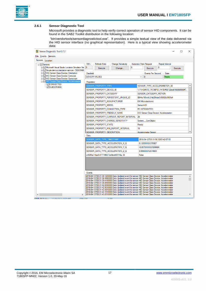
2.6.1 Sensor Diagnostic Tool
Microsoft provides a diagnostic tool to help verify correct operation of sensor HID components. It can be found in the SAB2 Toolkit distribution in the following location:
“bin/vendortools/sensordiagnostictool.exe”. It provides a simple textual view of the data delivered via the HID sensor interface (no graphical representation). Here is a typical view showing accelerometer data:

USER MANUAL Ɩ EM7180SFP
Copyright 2016, EM Microelectronic-Marin SA 7180SFP-MN02, Version 1.0, 20-May-16
18 www.emmicroelectronic.com
420005-A01, 3.0
2.6.2 Sensor HID Coordinate System
The SensorHID application reports sensor values in an East-North-Up coordinate system (aka “ENU”). The following figure illustrates the orientation of the SAB2 with respect to the ENU coordinates. Not shown is the Up (Z) dimension, which is upward from the top-side of the board:
The following table illustrates how this coordinate system would map acceleration values for various orientations of the board:
Board Orientation X Acceleration Y Acceleration Z Acceleration
Horizontal 0 0 1G
North end pointing up (vertical) 0 1G 0
East end pointing up (vertical) 1G 0 0
The above mapping holds true regardless of the sensor device installed on the SAB2. The developer should note, however, that the coordinate system is aligned with the native coordinate system of the EM7180SFP.

USER MANUAL Ɩ EM7180SFP
Copyright 2016, EM Microelectronic-Marin SA 7180SFP-MN02, Version 1.0, 20-May-16
19 www.emmicroelectronic.com
420005-A01, 3.0
2.7 SAB2 CONFIGURATION UTILITY (SAB2CONFIGUTIL)
This utility application provides a menu-driven user interface to perform various board configuration functions, as described in the table below:
Menu Selection Description
Program BLE Device Address This menu selection programs the 48 bit Bluetooth (BLE) device address, which is also used as a serial number for some applications.
To enable each board to have a unique device address, a section of the EEPROM on the LPC1549 is allocated to store this information. This application can set the address, which is then used by applications that need it, such as the BLE mouse application (SensorMouseBLEUSB).
Applications that use this information generally show it in the startup banner like this:
Device serial number/address = 0CF3EE010203
Clear BLE Persistent Cache The SensorMouseBLEUSB application uses a section of the EEPROM on the LPC1549 to store information about devices that have connected to the SAB2 via the BLE interface. Normally the user does not need to worry about this information, but it may be convenient to clear the persistent cache sometimes for BLE test purposes.
To use the application, you must have a bidirectional terminal attached to the serial port. The “putty” app is recommended (see Section 1.3.6).
First, load the app (SAB2ConfigUtil.bin) as described in Section 1.3.8.1. Then push the reset button and observe the banner text and the menu choices appearing on the device attached to the serial port.
The following illustrates a typical session to program the BLE device address:
#########################################################################
EM Microelectronic 718x SAB2 LPC1549: SAB2 Configuration Utility v3.03
Device serial number/address = 0CF3EE010203
Normal buttons detected
FlashDisk: Found
FlashDisk: Unprotect
FlashDisk: ProtectFlag=0 LockFlag=0
FlashDisk: Check map
FlashDisk: 1028096 used 3133440 free
FlashDisk: Check FAT
FlashDisk: Existing OEM name = MSDOS5.0
FlashDisk: FAT is OK.
Device detected:
ProductID: 7180
Revision: 02
ROM version: 2534
RAM version: 9151
Menu:
1 = Program BLE device address
2 = Clear BLE persistent cache
---
9 = Exit
Select function to perform:1
Current BLE Address: 0CF3EE010203
Enter last six hex digits of the BLE address: 112233
Full BLE Address Requested: 0CF3EE112233
Correct (y/n)?y
Programming...
Programmed BLE Address: 0CF3EE112233
Try again (y/n)?n
Done

USER MANUAL Ɩ EM7180SFP
Copyright 2016, EM Microelectronic-Marin SA 7180SFP-MN02, Version 1.0, 20-May-16
20 www.emmicroelectronic.com
420005-A01, 3.0
Once the application reaches the “Done” state, it is locked in an infinite loop and will ignore all further input on the serial port. If you wish to re-run the app, push the reset button.
To test the programming of the BLE device address (and serial number):
Ɩ Load and execute the SensorMouseBLEUSB.bin application
Ɩ Connect the USB port to a Windows PC
Ɩ Use the “Manage Bluetooth Devices” screen on the PC to pair with the SAB2
Ɩ Note: If you would rather use the normal mouse to control the desktop rather than the SAB2 mouse, use the SW1 and SW2 buttons to disable sending of mouse reports to the PC
Ɩ Start the “Device Manager” on the Windows PC system
Ɩ Select the “SENtral SAB2” device in the Bluetooth section as illustrated in the following screen snaps:
The SAB2 Bluetooth
device
The SAB2 Bluethooth
device address

USER MANUAL Ɩ EM7180SFP
Copyright 2016, EM Microelectronic-Marin SA 7180SFP-MN02, Version 1.0, 20-May-16
21 www.emmicroelectronic.com
420005-A01, 3.0
SAB2 HID serial number (the
same as the BLE device address

USER MANUAL Ɩ EM7180SFP
Copyright 2016, EM Microelectronic-Marin SA 7180SFP-MN02, Version 1.0, 20-May-16
22 www.emmicroelectronic.com
420005-A01, 3.0
3 APPENDIX A – QUICK START GUIDE TO BUILDING THE FIRMWARE
Prerequisites:
Ɩ Install LPCXpresso v7.8.0_426 at C:/nxp/LPCXpresso_7.8.0_426 (available from www.lpcware.com/lpcxpresso/home)
Ɩ Install the SAB2 Toolkit source distribution anywhere convenient. For purposes of this example we will use “C:/SAB2Toolkit” as the installation location.
Steps to Build the Firmware: 1. Start LPCXpresso.
2. Select File->Import->General->Existing Projects into Workspace
3. Select Next.
4. Click the “Select Root Directory” button and browse to the SAB2 firmware source folder (e.g. C:/SAB2Toolkit/src/sab).
5. Verify all the projects are automatically checked/selected (which is the default), then select Finish.
6. Select Project->Clean. Check the “Clean all projects” and “Build the entire workspace” checkboxes. Select OK.
7. Select the “Problems” tab and verify no build errors were encountered (Warnings are OK).
8. The application binary files will be in the “Debug” folder for each application:
Application Root Application Binary (relative to the root)
C:/SAB2Toolkit/src/sab/I2CHID Debug/I2CHID.bin
C:/SAB2Toolkit/src/sab/SAB2ConfigUtil Debug/SAB2ConfigUtil.bin
C:/SAB2Toolkit/src/sab/SensorJoystickUSB Debug/SensorJoystickUSB.bin
C:/SAB2Toolkit/src/sab/SensorMouseBLEUSB Debug/SensorMouseBLEUSB.bin
C:/SAB2Toolkit/src/sab/SensorReadTest Debug/SensorReadTest.bin
C:/SAB2Toolkit/src/sab/SensorSimpleExample Debug/SensorSimpleExample.bin
C:/SAB2Toolkit/src/sab/SensorHID Debug/SensorHID.bin
EM Microelectronic-Marin SA (“EM”) makes no warranties for the use of EM products, other than those expressly contained in EM's applicable General Terms of Sale, located at http://www.emmicroelectronic.com. EM assumes no responsibility for any errors which may have crept into this document, reserves the right to change devices or specifications detailed herein at any time without notice, and does not make any commitment to update the information contained herein. No licenses to patents or other intellectual property rights of EM are granted in connection with the sale of EM products, neither expressly nor implicitly. In respect of the intended use of EM products by customer, customer is solely responsible for observing existing patents and other intellectual property rights of third parties and for obtaining, as the case may be, the necessary licenses. Important note: The use of EM products as components in medical devices and/or medical applications, including but not limited to, safety and life supporting systems, where malfunction of such EM products might result in damage to and/or injury or death of persons is expressly prohibited, as EM products are neither destined nor qualified for use as components in such medical devices and/or medical applications. The prohibited use of EM products in such medical devices and/or medical applications is exclusively at the risk of the customer