Stainless Steel FRL’s - Wilkerson Corp
24
Stainless Steel FRL’s Air Preparation Units Catalog 9CW-BH-260 (Rev. 2)
Transcript of Stainless Steel FRL’s - Wilkerson Corp
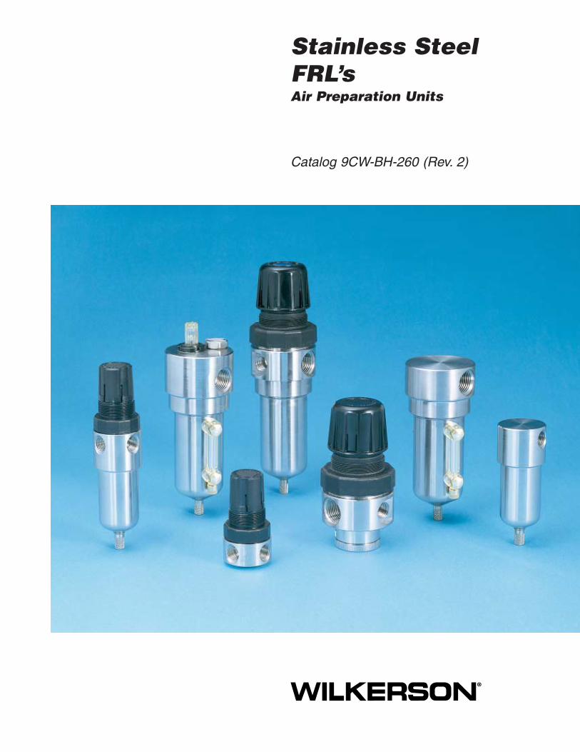
Stainless SteelFRL’sAir Preparation Units
Catalog 9CW-BH-260 (Rev. 2)

Wilkerson Operations
! WARNINGFAILURE OR IMPROPER SELECTION OR IMPROPER USE OF THE PRODUCTS AND/OR SYSTEMS DESCRIBED HEREINOR RELATED ITEMS CAN CAUSE DEATH, PERSONAL INJURY AND PROPERTY DAMAGE.This document and other information from The Company, its subsidiaries and authorized distributors provide product and/orsystem options for further investigation by users having technical expertise. It is important that you analyze all aspects of yourapplication including consequences of any failure, and review the information concerning the product or system in the currentproduct catalog. Due to the variety of operating conditions and applications for these products or systems, the user, through itsown analysis and testing, is solely responsible for making the final selection of the products and systems and assuring that allperformance, safety and warning requirements of the application are met.The products described herein, including without limitation, product features, specifications, designs, availability and pricing, aresubject to change by The Company and its subsidiaries at any time without notice.
Offer of SaleThe items described in this document are hereby offered for sale by The Company, its subsidiaries or its authorized distributors.This offer and its acceptance are governed by the provisions stated on the separate page of this document entitled “Offer of Sale”.
© Copyright 2003, Parker Hannifin Corporation. All Rights Reserved.
Distributed WorldwideWilkerson offers a complete line of innovative fluidpower products with features and operatingcharacteristics that meet customer expectations ofquality, performance, reliability and value. Wilkersonrepresentatives are located in most major citiesthroughout the world with additional manufacturingand sales affiliates in North and South America,Europe, Africa, Asia and the Pacific Rim Basin.
Wilkerson provides the
Total Systems Approach
to Air Preparation!

Wilkerson Operations 1
Air Line FiltersMiniature SF1 ................................................................................................................ 2-3Standard SF2 ................................................................................................................. 4-5
Air Line Coalescing FiltersMiniature SM1................................................................................................................ 6-7Standard SM2 ................................................................................................................ 8-9
Air Line RegulatorsMiniature SR1 ............................................................................................................ 10-11Standard SR2 ............................................................................................................ 12-13
Filter / Regulator “Piggybacks”Miniature SB1 ............................................................................................................ 14-15Standard SB2 ............................................................................................................ 16-17
Air Line LubricatorsStandard SL2 ............................................................................................................. 18-19
Offer of Sale ........................................................................................................................... 21
Catalog 9CW-BH-260 (Rev. 2)
Table of ContentsStainless Steel SeriesAir Preparation Units

2 Wilkerson Operations
Ordering Information
Features• Stainless Steel Construction handles
most corrosive environments.
• Fluorocarbon seals standard.
• Meets NACE specifications.
• High Flow: 1/4" – 23 SCFM §
Stainless Steel Series1/4" – Basic 1/8" Body
Catalog 9CW-BH-260 (Rev. 2)
Miniature SF1 Series
SF1 Filter – Miniature
SF1 Filter Dimensions
A C D1.56 0.31 3.69
40 mm 8 mm 94 mmE F
4.00 1.58102 mm 40 mm
Standard part numbers shown, for other models refer to ordering information below.§ SCFM = Standard cubic feet per minute at 90 PSIG inlet and 5 PSIG pressure drop.
Port NPT BSPPSize Manual Drain Manual Drain
1/4" SF1-02-SYV0 SF1-C2-SYV0
NOTE: Shaded = “Most Popular”.
D
C
E
A Dia.
Distance RequiredTo Remove All BowlsF
AutomaticDrain
ManualDrain
1 ISO, R228 (G SERIES)
“SF” Series Filters, Type “A” 5 micron elements:All Wilkerson Type “A” 5 micron elements meet orexceed ISO Class 3 for maximum particle size andconcentration of solid contaminants.
NOTE: All classes above refer to InternationalStandards Organization (ISO) standard 8573-1,pertaining to maximum particle size andconcentration of solid contaminants, andmaximum oil content.
SF1 – 0 2 – S Y V 0
Bowls / Drains
Y. Metal Bowl withoutSight Gauge / Manual Drain
Options
V. Fluorocarbon Seals
Pipe Size
2. 1/4 Inch
Thread Type
0. NPTC. BSPP1
Filter Element
S. 5 MicronT. 20 Micron
Options
0. None

Wilkerson Operations 3
0
1
2
3
4
5
0 5 10 15 20 25
Pre
ssu
re D
rop
- P
SIG
0
0 .5 .75.25 1.0 1.25 1.5
Flow - SCFM
Flow - dm /s
Pre
ssu
re D
rop
- b
ar
3
n
.1
.2
.3
Flow CharacteristicsSF1-02-SYV01/4 Inch Ports
25 PSIG 50 PSIG 75 PSIG 100 PSIGPrimary Pressure - PSIG
1.7 bar 3.4 bar 5.2 bar 6.9 barPrimary Pressure - bar
Stainless Steel SeriesAir Line Filters
Catalog 9CW-BH-260 (Rev. 2)
Technical Specifications – SF1
SF1 Filter Kits & AccessoriesFilter Element Kits –
Particulate (5 Micron) ............................................ SRP-96-001Particulate (20 Micron) .......................................... SRP-96-002
Manual Drain – ................................................................. SRP-96-008Pipe Nipple – 1/4" 316 Stainless Steel ........................... SRP-96-009
SpecificationsBowl Capacity ................................................................... 1.0 OuncesFilter Rating ............................................................................ 5 MicronUseful Retention† ............................................................... 0.4 OuncePort Threads ........................................................................... 1/4 InchPressure & Temperature Ratings ...... 0 to 300 PSIG (0 to 20.7 bar)
........ 40°F to 180°F (4°C to 82°C)Weight .......................................................................... 0.6 lb. (0.27 kg)
Materials of ConstructionBody ....................................................................... 316 Stainless SteelBowl ....................................................................... 316 Stainless SteelDrain ....................................................................... 316 Stainless SteelFilter Element ................................................................... PolyethyleneElement Holder ........................................................................... AcetalSeals ................................................................................ FluorocarbonDeflector ...................................................................................... Acetal
Operation First Stage Filtration:Air enters at inlet port and flows through deflectorplate (A) which causes a swirling action. Liquids andcoarse particles are forced to the bowl interior wall (B)by the centrifugal action of the swirling air. They arethen carried down the bowl wall by the force of gravity.The baffle (D) separates the lower portion of the bowlinto a “quiet zone” (E) where the removed liquid andparticles collect, unaffected by the swirling air, and aretherefore not reentrained into the flowing air.
Second Stage Filtration:After liquids and large particles are removed in thefirst stages of filtration, the air flows through element(C) where smaller particles are filtered out. The filteredair then passes downstream. Collected liquids andparticles in the “quiet zone” (E) should be drainedbefore their level reaches a height where they wouldbe reentrained in the flowing air. This can beaccomplished by unscrewing the drain valve (F)slightly until the liquid begins to drain.
Technical Information
AB
C
E
F
D
† Useful Retention refers to volume below the quiet zone baffle.

4 Wilkerson Operations
Features• Stainless Steel Construction handles
most corrosive environments.
• Meets NACE specifications.
• High Flow: 1/2" – 70 SCFM §
Stainless Steel Series1/2" – Basic 3/8" Body
Catalog 9CW-BH-260 (Rev. 2)
Standard SF2 Series
SF2 Filter – Standard
SF2 Filter Dimensions
A A1 B2.38 2.50 1.75
60 mm 64 mm 44 mmC D E
0.56 5.00 5.5614 mm 127 mm 141 mm
F2.12
54 mm
Standard part numbers shown, for other models refer to ordering information below.§ SCFM = Standard cubic feet per minute at 90 PSIG inlet and 5 PSIG pressure drop.
Port NPT BSPPSize Manual Drain Auto Float Drain Manual Drain Auto Float Drain
1/2" SF2-04-SYV0 SF2-04-SXV0 SF2-C4-SYV0 SF2-C4-SXV0
AutomaticDrain
TwistDrain
D E
C
B Dia. Distance RequiredTo Remove All BowlsRegardless OfDrain Option
F
A Dia.
Optional Sight GaugeA1
Ordering Information
NOTE: Shaded = “Most Popular”.
Options
V. Fluorocarbon Seals
Pipe Size
4. 1/2 Inch
Thread Type
0. NPTC. BSPP1
Filter Element
S. 5 MicronF. 40 Micron
1 ISO, R228 (G SERIES)
“SF” Series Filters, Type “A” 5 micron elements:All Wilkerson Type “A” 5 micron elements meet orexceed ISO Class 3 for maximum particle size andconcentration of solid contaminants.
NOTE: All classes above refer to InternationalStandards Organization (ISO) standard 8573-1,pertaining to maximum particle size andconcentration of solid contaminants, andmaximum oil content.
Options
0. None
SF2 – 0 4 – S Y V 0
Bowls / Drains
Y. Metal Bowl without Sight Gauge / Manual DrainX. Metal Bowl without Sight Gauge / Auto DrainL. Metal Bowl with Sight Gauge / Manual DrainH. Metal Bowl with Sight Gauge / Auto Drain

Wilkerson Operations 5
0
1
2
3
4
5
0 10 20 30 40 50 60 70 80 90 100
Pre
ssu
re D
rop
- P
SIG
0
0 5 10 15 20 25 30 35 40 45
Flow - SCFM
Flow - dm /s
Pre
ssu
re D
rop
- b
ar
3
n
.1
.2
.3
Flow CharacteristicsSF2-04-SYV01/2 Inch Ports
25 PSIG 50 PSIG 75 PSIG 100 PSIGPrimary Pressure - PSIG
1.7 bar 3.4 bar 5.2 bar 6.9 barPrimary Pressure - bar
Stainless Steel SeriesAir Line Filters
Catalog 9CW-BH-260 (Rev. 2)
Technical Specifications – SF2
SF2 Filter Kits & AccessoriesDrain Kit – Automatic Drain ............................................ SRP-96-007
Manual Drain ................................................. SRP-96-008Filter Element Kits – Particulate (40 Micron) .................. SRP-96-004
Particulate (5 Micron) .................... SRP-96-003Liquid Level Sight Gauge Kit .......................................... SRP-96-026Pipe Nipple – 1/2" 316 Stainless Steel ............................ SRP-96-010
SpecificationsBowl Capacity ................................................................... 4.0 OuncesFilter Rating ............................................................................ 5 MicronUseful Retention† ............................................................... 1.7 OuncePort Threads ........................................................................... 1/2 InchPressure & Temperature Ratings –
Manual Drain – 0 to 300 PSIG (0 to 20.7 bar)40°F to 180°F (4°C to 82°C)
Automatic Drain – 15 to 175 PSIG (1 to 12 bar)40°F to 120°F (4°C to 49°C)
Weight ......................................................................... 1.9 lb. (0.85 kg)
Materials of ConstructionBody ....................................................................... 316 Stainless SteelBowl ....................................................................... 316 Stainless SteelDrain ....................................................................... 316 Stainless SteelFilter Element ................................................................... PolyethyleneElement Holder ........................................................................... AcetalSeals ................................................................................ FluorocarbonDeflector ...................................................................................... Acetal
Operation First Stage Filtration:Air enters at inlet port and flows through deflectorplate (A) which causes a swirling action. Liquids andcoarse particles are forced to the bowl interior wall (B)by the centrifugal action of the swirling air. They arethen carried down the bowl wall by the force of gravity.The baffle (D) separates the lower portion of the bowlinto a “quiet zone” (E) where the removed liquid andparticles collect, unaffected by the swirling air, and aretherefore not reentrained into the flowing air.
Second Stage Filtration:After liquids and large particles are removed in thefirst stages of filtration, the air flows through element(C) where smaller particles are filtered out. The filteredair then passes downstream. Collected liquids andparticles in the “quiet zone” (E) should be drainedbefore their level reaches a height where they wouldbe reentrained in the flowing air. This can beaccomplished by unscrewing the drain valve (F)slightly until the liquid begins to drain.
Technical Information
A
B
C
E
F
D
† Useful Retention refers to volume below the quiet zone baffle.

6 Wilkerson Operations
Features• Stainless Steel Construction handles
most corrosive environments.
• Meets NACE specifications.
• High Flow: 1/4" – 16 SCFM §
Stainless Steel Series1/4" – Basic 1/8" Body
Catalog 9CW-BH-260 (Rev. 2)
Miniature SM1 Series
SM1 Coalescing Filter – Miniature
D
C
E
A Dia.
Distance RequiredTo Remove All BowlsF
Standard part numbers shown, for other models refer to ordering information below.§ SCFM = Standard cubic feet per minute at 90 PSIG inlet and 5 PSIG pressure drop.
Port NPT BSPPSize Manual Drain Manual Drain
1/4" SM1-02-EYV0 SM1-C2-EYV0
SM1 Coalescing Filter
Dimensions
A C D1.56 0.31 3.69
40 mm 8 mm 94 mmE F
4.00 1.58102 mm 40 mm
Ordering Information
NOTE: Shaded = “Most Popular”.
1 ISO, R228 (G SERIES)
SM1 – 0 2 – E Y V 0
Bowls / Drains
Y. Metal Bowl withoutSight Gauge / Manual Drain
Options
V. Fluorocarbon Seals
Pipe Size
2. 1/4 Inch
Thread Type
0. NPTC. BSPP1
Coalescing Element
E. 0.3 Micron, Oil Removing
Options
0. None
Wilkerson Operations 7
Stainless Steel SeriesCoalescing Filters (Oil Removal)
Catalog 9CW-BH-260 (Rev. 2)
Technical Specifications – SM1
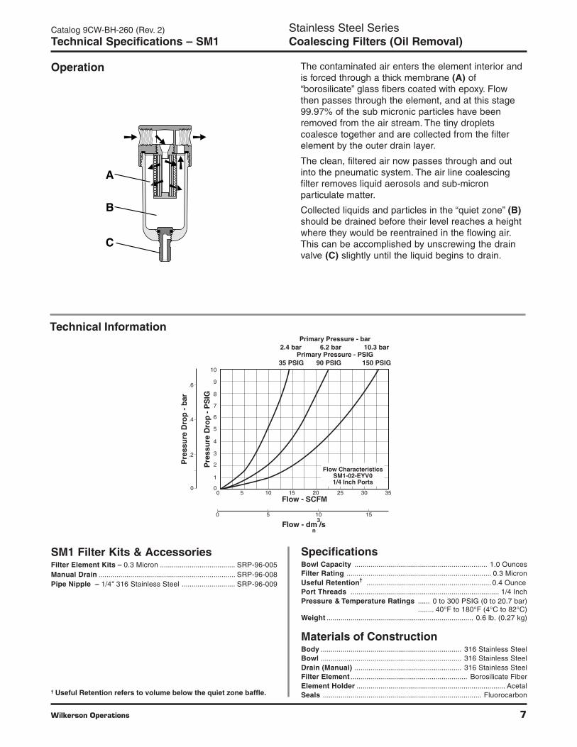
Operation
SM1 Filter Kits & AccessoriesFilter Element Kits – 0.3 Micron ...................................... SRP-96-005Manual Drain ..................................................................... SRP-96-008Pipe Nipple – 1/4" 316 Stainless Steel ........................... SRP-96-009
SpecificationsBowl Capacity ................................................................... 1.0 OuncesFilter Rating ......................................................................... 0.3 MicronUseful Retention† ............................................................... 0.4 OuncePort Threads ........................................................................... 1/4 InchPressure & Temperature Ratings ...... 0 to 300 PSIG (0 to 20.7 bar)
........ 40°F to 180°F (4°C to 82°C)Weight .......................................................................... 0.6 lb. (0.27 kg)
Materials of ConstructionBody ....................................................................... 316 Stainless SteelBowl ....................................................................... 316 Stainless SteelDrain (Manual) ...................................................... 316 Stainless SteelFilter Element ........................................................... Borosilicate FiberElement Holder ........................................................................... AcetalSeals ................................................................................ Fluorocarbon
Technical Information
The contaminated air enters the element interior andis forced through a thick membrane (A) of“borosilicate” glass fibers coated with epoxy. Flowthen passes through the element, and at this stage99.97% of the sub micronic particles have beenremoved from the air stream. The tiny dropletscoalesce together and are collected from the filterelement by the outer drain layer.
The clean, filtered air now passes through and outinto the pneumatic system. The air line coalescingfilter removes liquid aerosols and sub-micronparticulate matter.
Collected liquids and particles in the “quiet zone” (B)should be drained before their level reaches a heightwhere they would be reentrained in the flowing air.This can be accomplished by unscrewing the drainvalve (C) slightly until the liquid begins to drain.
A
C
B
0
1
2
3
6
7
8
9
10
4
5
0 5 10 15 20 25 30 35
Pre
ssu
re D
rop
- P
SIG
0
0 5 10 15
Flow - SCFM
Flow - dm /s
Pre
ssu
re D
rop
- b
ar
3
n
.2
.4
.6
Flow CharacteristicsSM1-02-EYV01/4 Inch Ports
35 PSIG 90 PSIG 150 PSIGPrimary Pressure - PSIG
2.4 bar 6.2 bar 10.3 barPrimary Pressure - bar
† Useful Retention refers to volume below the quiet zone baffle.

8 Wilkerson Operations
Bowls / Drains
Y. Metal Bowl without Sight Gauge / Manual DrainX. Metal Bowl without Sight Gauge / Auto DrainL. Metal Bowl with Sight Gauge / Manual DrainH. Metal Bowl with Sight Gauge / Auto Drain
Features• Stainless Steel Construction handles
most corrosive environments.
• Meets NACE specifications.
• High Flow: 1/2" – 45 SCFM §
Stainless Steel Series1/2" – Basic 3/8" Body
Catalog 9CW-BH-260 (Rev. 2)
Standard SM2 Series
SM2 Coalescing Filter – Standard
Standard part numbers shown, for other models refer to ordering information below.§ SCFM = Standard cubic feet per minute at 90 PSIG inlet and 5 PSIG pressure drop.
Port NPT BSPPSize Manual Drain Auto Float Drain Manual Drain Auto Float Drain
1/2" SM2-04-EYV0 SM2-04-EXV0 SM2-C4-EYV0 SM2-C4-EXV0
D E
C
B Dia. Distance RequiredTo Remove All BowlsRegardless OfDrain Option
F
A Dia.
Optional Sight GaugeA1
SM2 Coalescing Filter
Dimensions
A A1 B2.38 2.50 1.75
60 mm 64 mm 44 mmC D E
0.56 5.00 5.5614 mm 127 mm 141 mm
F2.12
54 mm
Ordering Information
NOTE: Shaded = “Most Popular”.
1 ISO, R228 (G SERIES)
SM2 – 0 4 – E Y V 0
Options
V. Fluorocarbon Seals
Pipe Size
4. 1/2 Inch
Thread Type
0. NPTC. BSPP1
Coalescing Element
E. 0.3 Micron,Oil Removing
Options
0. None

Wilkerson Operations 9
0
1
2
3
6
7
8
9
10
4
5
0 10 20 30 40 50 60 70 80
Pre
ssu
re D
rop
- P
SIG
0
0 5 10 15 20 25 30 35
Flow - SCFM
Flow - dm /s
Pre
ssu
re D
rop
- b
ar
3
n
.2
.4
.6
Flow CharacteristicsSM2-04-EYV01/2 Inch Ports
35 PSIG 90 PSIG 150 PSIGPrimary Pressure - PSIG
2.4 bar 6.2 bar 10.3 barPrimary Pressure - bar
Stainless Steel SeriesCoalescing Filters (Oil Removal)
Catalog 9CW-BH-260 (Rev. 2)
Technical Specifications – SM2
SM2 Filter Kits & AccessoriesDrain Kit – Automatic Drain ............................................ SRP-96-007
Manual Drain ................................................. SRP-96-008Filter Element Kits – 0.3 Micron ...................................... SRP-96-006Liquid Level Sight Gauge Kit .......................................... SRP-96-026Pipe Nipple – 1/2" 316 Stainless Steel ............................ SRP-96-010
SpecificationsBowl Capacity ................................................................... 4.0 OuncesFilter Rating ......................................................................... 0.3 MicronUseful Retention† ............................................................... 1.7 OuncePort Threads ........................................................................... 1/2 InchPressure & Temperature Ratings –
Manual Drain – 0 to 300 PSIG (0 to 20.7 bar)40°F to 180°F (4°C to 82°C)
Automatic Drain – 0 to 175 PSIG (0 to 12 bar)40°F to 120°F (4°C to 49°C)
Weight ......................................................................... 1.9 lb. (0.85 kg)
Materials of ConstructionBody ....................................................................... 316 Stainless SteelBowl ....................................................................... 316 Stainless SteelDrain ....................................................................... 316 Stainless SteelFilter Element ........................................................... Borosilicate FiberElement Holder ........................................................................... AcetalSeals ................................................................................ Fluorocarbon
Operation
Technical Information
The contaminated air enters the element interior andis forced through a thick membrane (A) of“borosilicate” glass fibers coated with epoxy. Flowthen passes through the element, and at this stage99.97% of the sub micronic particles have beenremoved from the air stream. The tiny dropletscoalesce together and are collected from the filterelement by the outer drain layer.
The clean, filtered air now passes through and outinto the pneumatic system. The air line coalescingfilter removes liquid aerosols and sub-micronparticulate matter.
Collected liquids and particles in the “quiet zone” (B)should be drained before their level reaches a heightwhere they would be reentrained in the flowing air.This can be accomplished by unscrewing the drainvalve (C) slightly until the liquid begins to drain.
A
C
B
† Useful Retention refers to volume below the quiet zone baffle.

10 Wilkerson Operations
Features• Stainless Steel Construction handles
most corrosive environments.
• Large diaphragm to valve area ratio forprecise regulation and high flow capacity.
• Meets NACE specifications.
• High Flow: 1/4" – 12 SCFM §
Stainless Steel Series1/4" – Basic 1/8" Body
Catalog 9CW-BH-260 (Rev. 2)
Miniature SR1 Series
SR1 Regulator – Miniature
CE
D
ADia.
Standard part numbers shown, for other models refer to ordering information below.§ SCFM = Standard cubic feet per minute at 100 PSIG inlet, 75 PSIG no flow secondary setting and
25% pressure drop.
Port NPT BSPPSize
1/4" SR1-02-LA00 SR1-C2-LA00
SR1 Regulator Dimensions
A C C11.56 2.56 2.17
40 mm 65 mm 55 mmD E E1
0.50 3.06 2.6713 mm 78 mm 68 mm
Ordering Information
NOTE: Shaded = “Most Popular”.
1 ISO, R228 (G SERIES)
SR1 – 0 2 – L A 0 0
Gauge Port Size
A. 1/4" Gauge Port
Pipe Size
2. 1/4 Inch
Thread Type
0. NPTC. BSPP1
Regulator
J. 0-25 PSIG (0-1.7 bar), RelievingK. 0-60 PSIG (0-4.1 bar), RelievingL. 0-125 PSIG (0-8.6 bar), RelievingV. 0-25 PSIG (0-1.7 bar), Non-RelievingX. 0-60 PSIG (0-4.1 bar), Non-RelievingY. 0-125 PSIG (0-8.6 bar), Non-Relieving
Options
0. None
Options
0. NoneS. Stainless Steel Bonnet
C1E1
D
ADia.

Wilkerson Operations 11
! WARNING
Product rupture can cause serious injury.Do not connect regulator to bottled gas.
Do not exceed maximum primary pressure rating.
0
20
30
50
10
40
60
70
90
80
100
0 2 4 6 8 10 12 14 16 18 20
Pre
ssu
re D
rop
- P
SIG
0
0 .1 .3 .5 .7 .9 1.1 1.3
Flow - SCFM
Flow - dm /s
Pre
ssu
re D
rop
- b
ar
3
n
1
2
3
4
5
6
Flow CharacteristicsSR1-02-LA00
1/4 Inch Ports100 PSIG (6.9 bar Primary Pressure
Stainless Steel SeriesAir Line Regulators
Catalog 9CW-BH-260 (Rev. 2)
Technical Specifications – SR1
Operation
SpecificationsGauge Port .............................................................................. 1/4 InchPort Threads ........................................................................... 1/4 InchPressure & Temperature Ratings – 300 PSIG Max (20.7 bar)
40°F to 150°F (4°C to 66°C)Weight ......................................................................... 0.5 lb. (0.23 kg)
Materials of ConstructionBody ....................................................................... 316 Stainless SteelBonnet ......................................................................................... AcetalDiaphragm and Seals .................................................... FluorocarbonKnob ............................................................................... PolypropoleneSprings .................................................................. 316 Stainless SteelValve Assembly and Bottom Plug ...................... 316 Stainless Steel
SR1 Regulator Kits & AccessoriesBonnet Kit (Black Knob Included) ................................. SRP-96-017Gauge – 0 to 160 PSIG (0 to 1100 kPa) ........................... SRP-96-021Panel Mount Nut ............................................................... SRP-96-019Pipe Nipple – 1/4" 316 Stainless Steel ........................... SRP-96-009Service Kit – Relieving ................................................... SRP-96-013
Non-Relieving ............................................ SRP-96-014
Technical Information
With the adjusting knob (A) turned fully counter-clockwise (no spring load), and pressure supplied tothe regulator inlet port, the valve poppet assembly (B)is closed. Turning the adjusting knob clockwise appliesa load to control spring (C). This load causes thediaphragm (D) and the valve poppet assembly (B) tomove downward allowing flow across the seat area (E)created between the poppet assembly and the seat.Pressure in the downstream line is sensed below thediaphragm (D) and offsets the load of spring (C). Asdownstream pressure rises, poppet assembly (B) anddiaphragm (D) move upward until the area (E) is closedand the load of the spring (C) and pressure underdiaphragm (D) are in balance. A reduced outletpressure has now been obtained, depending on springload. Creating a demand downstream, such as openinga valve, results in a reduced pressure under thediaphragm (D). The load of control spring (C) nowcauses the poppet assembly to move downwardopening seat area (E) allowing air to flow to meet thedownstream demand. The flow of downstream air ismetered by the amount of opening (E).
Should downstream pressure exceed the desiredregulated pressure, the excess pressure will cause thediaphragm (D) to move upward against control spring(C), open vent hole (F), and vent the excess pressureto atmosphere through the hole in the bonnet (H). (Thisoccurs in the relieving type regulator only.)
H
F
E
A
D
C
B
Note: Order pressure gauge and panel mount nut separately.Note: 1.19" dia. (30.2 mm) hole required for panel mounting
(order panel nut separately).
H
F
E
A
D
C
B

12 Wilkerson Operations
Features• Stainless Steel Construction handles
most corrosive environments.
• Large diaphragm to valve area ratio forprecise regulation and high flow capacity.
• Meets NACE specifications.
• High Flow: 1/2" – 80 SCFM §
Stainless Steel Series1/2" – Basic 3/8" Body
Catalog 9CW-BH-260 (Rev. 2)
Standard SR2 Series
SR2 Regulator – Standard
A
B
C
E
D
Ordering Information
NOTE: Shaded = “Most Popular”.
1 ISO, R228 (G SERIES)
SR2 – 0 4 – L A 0 0
Gauge Port Size
A. 1/4" Gauge Port
Pipe Size
4. 1/2 Inch
Thread Type
0. NPTC. BSPP1
Regulator
K. 0-60 PSIG (0-4.1 bar), RelievingL. 0-125 PSIG (0-8.6 bar), RelievingM. 0-250 PSIG (0-17.2 bar), RelievingX. 0-60 PSIG (0-4.1 bar), Non-RelievingY. 0-125 PSIG (0-8.6 bar), Non-RelievingZ. 0-250 PSIG (0-17.2 bar), Non-Relieving
Options
0. None
SR2 Regulator Dimensions
A B C2.34 2.43 3.59
60 mm 62 mm 91 mmD E
1.38 4.9735 mm 126 mm
Standard part numbers shown, for other models refer to ordering information below.§ SCFM = Standard cubic feet per minute at 100 PSIG inlet, 75 PSIG no flow secondary setting and
25% pressure drop.
Port NPT BSPPSize
1/2" SR2-04-LA00 SR2-C4-LA00
Options
0. None

Wilkerson Operations 13
0
20
30
50
10
40
60
70
90
80
100
0 10 20 30 40 50 60 70 80 90 100
Pre
ssu
re D
rop
- P
SIG
0
0 5 10 15 20 25 30 35 40 45
Flow - SCFM
Flow - dm /s
Pre
ssu
re D
rop
- b
ar
3
n
1
2
3
4
5
6
Flow CharacteristicsSR2-04-LA00
1/2 Inch Ports100 PSIG (6.9 bar Primary Pressure
Stainless Steel SeriesAir Line Regulators
Catalog 9CW-BH-260 (Rev. 2)
Technical Specifications – SR2
SpecificationsGauge Port .............................................................................. 1/4 InchPort Threads ........................................................................... 1/2 InchPressure & Temperature Ratings – 300 PSIG Max (20.7 bar)
40°F to 150°F (4°C to 66°C)Weight ....................................................................... 1.79 lb. (0.81 kg)
Materials of ConstructionBody ....................................................................... 316 Stainless SteelBonnet ......................................................................................... AcetalDiaphragm and Seals .................................................... FluorocarbonKnob ................................................................................ PolypropyleneSprings .................................................................. 316 Stainless SteelValve Assembly and Bottom Plug ...................... 316 Stainless Steel
SR2 Regulator Kits & AccessoriesBonnet Kit (Knob Included) ............................................ SRP-96-018Gauge – 0 to 160 PSIG (0 to 1100 kPa) ........................... SRP-96-022Panel Mount Nut ............................................................... SRP-96-020Pipe Nipple – 1/2" 316 Stainless Steel ........................... SRP-96-010Service Kit – Relieving ................................................... SRP-96-011
Non-Relieving ............................................ SRP-96-012
Operation
D
A
C
B
H
F
E
With the adjusting knob (A) turned fully counter-clockwise (no spring load), and pressure supplied tothe regulator inlet port, the valve poppet assembly (B)is closed. Turning the adjusting knob clockwise appliesa load to control spring (C). This load causes thediaphragm (D) and the valve poppet assembly (B) tomove downward allowing flow across the seat area (E)created between the poppet assembly and the seat.Pressure in the downstream line is sensed below thediaphragm (D) and offsets the load of spring (C). Asdownstream pressure rises, poppet assembly (B) anddiaphragm (D) move upward until the area (E) is closedand the load of the spring (C) and pressure underdiaphragm (D) are in balance. A reduced outletpressure has now been obtained, depending on springload. Creating a demand downstream, such as openinga valve, results in a reduced pressure under thediaphragm (D). The load of control spring (C) nowcauses the poppet assembly to move downwardopening seat area (E) allowing air to flow to meet thedownstream demand. The flow of downstream air ismetered by the amount of opening (E).
Should downstream pressure exceed the desiredregulated pressure, the excess pressure will cause thediaphragm (D) to move upward against control spring(C), open vent hole (F), and vent the excess pressureto atmosphere through the hole in the bonnet (H). (Thisoccurs in the relieving type regulator only.)
Note: Order pressure gauge and panel mount nut separately.Note: 1.75" dia. (44.5 mm) hole required for panel mounting
(order panel nut separately).
Technical Information
! WARNING
Product rupture can cause serious injury.Do not connect regulator to bottled gas.
Do not exceed maximum primary pressure rating.
14 Wilkerson Operations
D D
CC1
EE1
A Dia. A Dia.
F FDistance RequiredTo Remove All Bowls
Bowls / Drains
Y. Metal Bowl without Sight Gauge /Manual Drain
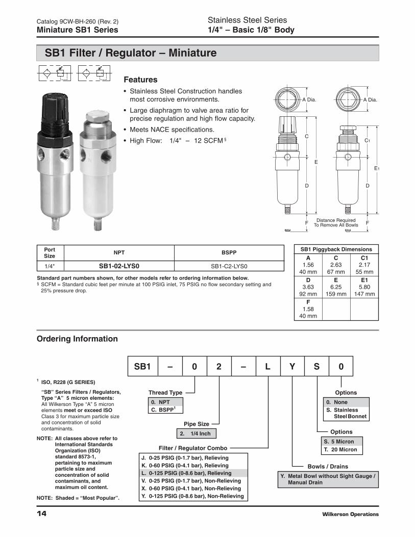
Features• Stainless Steel Construction handles
most corrosive environments.
• Large diaphragm to valve area ratio forprecise regulation and high flow capacity.
• Meets NACE specifications.
• High Flow: 1/4" – 12 SCFM §
Stainless Steel Series1/4" – Basic 1/8" Body
Catalog 9CW-BH-260 (Rev. 2)
Miniature SB1 Series
SB1 Filter / Regulator – Miniature➤
➤
➤
➤
➤
➤
Standard part numbers shown, for other models refer to ordering information below.§ SCFM = Standard cubic feet per minute at 100 PSIG inlet, 75 PSIG no flow secondary setting and
25% pressure drop.
Port NPT BSPPSize
1/4" SB1-02-LYS0 SB1-C2-LYS0
Ordering Information
NOTE: Shaded = “Most Popular”.
1 ISO, R228 (G SERIES)
“SB” Series Filters / Regulators,Type “A” 5 micron elements:All Wilkerson Type “A” 5 micronelements meet or exceed ISOClass 3 for maximum particle sizeand concentration of solidcontaminants.
NOTE: All classes above refer toInternational StandardsOrganization (ISO)standard 8573-1,pertaining to maximumparticle size andconcentration of solidcontaminants, andmaximum oil content.
SB1 – 0 2 – L Y S 0
Pipe Size
2. 1/4 Inch
Thread Type
0. NPTC. BSPP1
Filter / Regulator Combo
J. 0-25 PSIG (0-1.7 bar), RelievingK. 0-60 PSIG (0-4.1 bar), RelievingL. 0-125 PSIG (0-8.6 bar), RelievingV. 0-25 PSIG (0-1.7 bar), Non-RelievingX. 0-60 PSIG (0-4.1 bar), Non-RelievingY. 0-125 PSIG (0-8.6 bar), Non-Relieving
Options
S. 5 MicronT. 20 Micron
Options
0. NoneS. Stainless
SteelBonnet
SB1 Piggyback Dimensions
A C C11.56 2.63 2.17
40 mm 67 mm 55 mmD E E1
3.63 6.25 5.8092 mm 159 mm 147 mm
F1.58
40 mm

Wilkerson Operations 15
L
F
G
D
A
B
K
C
E
J
H
F
G
D C
E
J
H
L
AB
K
0
20
30
50
10
40
60
70
90
80
100
0 2 4 6 8 10 12 14 16 18 20
Pre
ssu
re D
rop
- P
SIG
0
0 .1 .3 .5 .7 .9 1.1 1.3
Flow - SCFM
Flow - dm /s
Pre
ssu
re D
rop
- b
ar
3
n
1
2
3
4
5
6
Flow CharacteristicsSB1-02-LYS0
1/4 Inch Ports100 PSIG (6.9 bar Primary Pressure
Stainless Steel SeriesAir Line Filter / Regulators
Catalog 9CW-BH-260 (Rev. 2)
Technical Specifications – SB1
Operation
SB1 Regulator Kits & AccessoriesBonnet Kit (Black Knob Included) ................................. SRP-96-017Filter Element Kits –
Particulate (5 Micron) ................................... SRP-96-001Particulate (20 Micron) ................................. SRP-96-002
Gauge – 0 to 160 PSIG (0 to 1100 kPa) ........................... SRP-96-021Manual Drain ..................................................................... SRP-96-008Panel Mount Nut ............................................................... SRP-96-019Pipe Nipple – 1/4" 316 Stainless Steel ............................ SRP-96-009Service Kit – Relieving .................................................... SRP-96-015
Non-Relieving ............................................. SRP-96-016
SpecificationsBowl Capacity ................................................................... 1.0 Ounces
Technical Information
Turning the adjusting knob clockwise applies a load tocontrol spring (B) which forces diaphragm (C) andvalve poppet assembly (D) to move downwardallowing filtered air to flow through the seat area (E)created between the poppet assembly and the seat.“First stage filtration”. Air pressure supplied to theinlet port is directed through deflector plate (F)causing a swirling centrifugal action forcing liquids andcoarse particles to the inner bowl wall (G) and downbelow the lower baffle (H) to the quiet zone. Afterliquids and large particles are removed in the firststage of filtration “second stage filtration” occurs asair flows through element (J) where smaller particlesare filtered out and retained. The air flow now passesthrough seat area (E) to the outlet port of the unit.Pressure in the downstream line is sensed below thediaphragm (C) and offsets the load of spring (B).When downstream pressure reaches the set-point,poppet valve assembly (D) and diaphragm (C) moveupward closing seat area (E). Should downstreampressure exceed the desired regulated pressure, theexcess pressure will cause the diaphragm (C) to moveupward opening vent hole (K) venting the excesspressure to atmosphere through the hole in the bonnet(L). (This occurs in the standard relieving type filter/regulators only.)
Filter Rating ............................................................................ 5 MicronGauge Port .............................................................................. 1/4 InchPort Threads ........................................................................... 1/4 InchPressure & Temperature Ratings – 300 PSIG Max (20.7 bar)
40°F to 150°F (4°C to 66°C)Useful Retention† ............................................................... 0.4 OunceWeight ......................................................................... 0.8 lb. (0.36 kg)
Materials of ConstructionBody ....................................................................... 316 Stainless SteelBowl ....................................................................... 316 Stainless SteelDrain ........................................................................ 316 Stainless SteelFilter Elements (Type A) .................................................. PolyethyleneElement Holder / Deflector / Bonnet ........................................ AcetalDiaphragm and Seals .................................................... FluorocarbonValve Assembly and Bottom Plug ...................... 316 Stainless SteelSprings .................................................................. 316 Stainless SteelKnob ................................................................................ Polypropylene
Note: Order pressure gauge and panel mount nut separately.Note: 1.19" dia. (30.2 mm) hole required for panel mounting
(order panel nut separately).† Useful Retention refers to volume below the quiet zone baffle.
! WARNING
Product rupture can cause serious injury.Do not connect regulator to bottled gas.
Do not exceed maximum primary pressure rating.
16 Wilkerson Operations
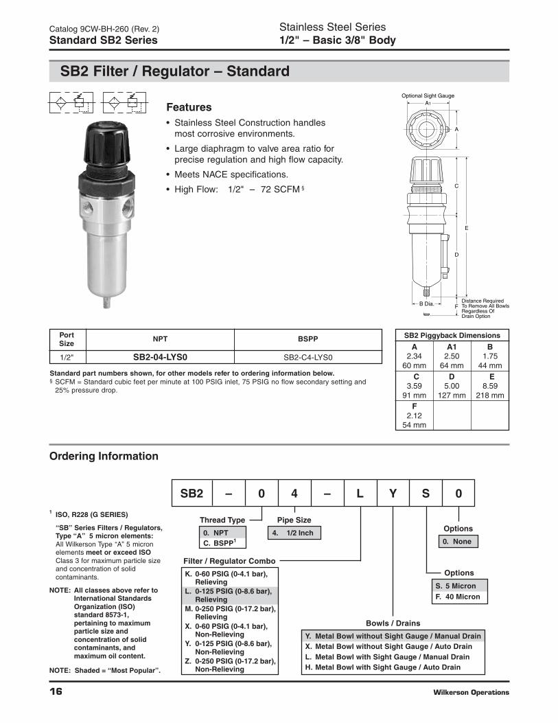
Features• Stainless Steel Construction handles
most corrosive environments.
• Large diaphragm to valve area ratio forprecise regulation and high flow capacity.
• Meets NACE specifications.
• High Flow: 1/2" – 72 SCFM §
Stainless Steel Series1/2" – Basic 3/8" Body
Catalog 9CW-BH-260 (Rev. 2)
Standard SB2 Series
SB2 Filter / Regulator – Standard➤
➤
➤
➤
➤
➤
D
E
C
B Dia. Distance RequiredTo Remove All BowlsRegardless OfDrain Option
F
A
Optional Sight GaugeA1
Bowls / Drains
Y. Metal Bowl without Sight Gauge / Manual DrainX. Metal Bowl without Sight Gauge / Auto DrainL. Metal Bowl with Sight Gauge / Manual DrainH. Metal Bowl with Sight Gauge / Auto Drain
Ordering Information
NOTE: Shaded = “Most Popular”.
SB2 – 0 4 – L Y S 0
Pipe Size
4. 1/2 Inch
Thread Type
0. NPTC. BSPP1
Filter / Regulator Combo
K. 0-60 PSIG (0-4.1 bar),Relieving
L. 0-125 PSIG (0-8.6 bar),Relieving
M. 0-250 PSIG (0-17.2 bar),Relieving
X. 0-60 PSIG (0-4.1 bar),Non-Relieving
Y. 0-125 PSIG (0-8.6 bar),Non-Relieving
Z. 0-250 PSIG (0-17.2 bar),Non-Relieving
SB2 Piggyback Dimensions
A A1 B2.34 2.50 1.75
60 mm 64 mm 44 mmC D E
3.59 5.00 8.5991 mm 127 mm 218 mm
F2.12
54 mm
Standard part numbers shown, for other models refer to ordering information below.§ SCFM = Standard cubic feet per minute at 100 PSIG inlet, 75 PSIG no flow secondary setting and
25% pressure drop.
Port NPT BSPPSize
1/2" SB2-04-LYS0 SB2-C4-LYS0
Options
S. 5 MicronF. 40 Micron
Options
0. None
1 ISO, R228 (G SERIES)
“SB” Series Filters / Regulators,Type “A” 5 micron elements:All Wilkerson Type “A” 5 micronelements meet or exceed ISOClass 3 for maximum particle sizeand concentration of solidcontaminants.
NOTE: All classes above refer toInternational StandardsOrganization (ISO)standard 8573-1,pertaining to maximumparticle size andconcentration of solidcontaminants, andmaximum oil content.

Wilkerson Operations 17
F
G
J
B
D
K
A
H
C
L
E
0
20
30
50
10
40
60
70
90
80
100
0 10 20 30 40 50 60 70 80 90 100
Pre
ssu
re D
rop
- P
SIG
0
0 5 10 15 20 25 30 35 40 45
Flow - SCFM
Flow - dm /s
Pre
ssu
re D
rop
- b
ar
3
n
1
2
3
4
5
6
Flow CharacteristicsSB2-04-LYS0
1/2 Inch Ports100 PSIG (6.9 bar Primary Pressure
Stainless Steel SeriesAir Line Filter / Regulators
Catalog 9CW-BH-260 (Rev. 2)
Technical Specifications – SB2
Operation
Technical Information
Turning the adjusting knob clockwise applies a load tocontrol spring (B) which forces diaphragm (C) andvalve poppet assembly (D) to move downwardallowing filtered air to flow through the seat area (E)created between the poppet assembly and the seat.“First stage filtration”. Air pressure supplied to theinlet port is directed through deflector plate (F) causinga swirling centrifugal action forcing liquids and coarseparticles to the inner bowl wall (G) and down below thelower baffle (H) to the quiet zone. After liquids andlarge particles are removed in the first stage of filtration“second stage filtration” occurs as air flows throughelement (J) where smaller particles are filtered out andretained. The air flow now passes through seat area(E) to the outlet port of the unit. Pressure in thedownstream line is sensed below the diaphragm (C)and offsets the load of spring (B). When downstreampressure reaches the set-point, poppet valve assembly(D) and diaphragm (C) move upward closing seat area(E). Should downstream pressure exceed the desiredregulated pressure, the excess pressure will cause thediaphragm (C) to move upward opening vent hole (K)venting the excess pressure to atmosphere throughthe hole in the bonnet (L). (This occurs in the standardrelieving type filter/regulators only.)
SB2 Regulator Kits & AccessoriesBonnet Kit (Knob Included) ............................................ SRP-96-018Filter Element Kits –
Particulate (5 Micron) ................................... SRP-96-003Particulate (40 Micron) ................................. SRP-96-004
Gauge – 0 to 160 PSIG (0 to 1100 kPa) ........................... SRP-96-022Liquid Level Sight Gauge Kit .......................................... SRP-96-026Automatic Drain ............................................................... SRP-96-007Manual Drain ..................................................................... SRP-96-008Panel Mount Nut ............................................................... SRP-96-020Pipe Nipple – 1/2" 316 Stainless Steel ............................ SRP-96-010Service Kit – Relieving .................................................... SRP-96-011
Non-Relieving ............................................. SRP-96-012
SpecificationsBowl Capacity ................................................................... 4.0 OuncesFilter Rating ............................................................................ 5 MicronGauge Port .............................................................................. 1/4 InchPort Threads ........................................................................... 1/2 InchPressure & Temperature Ratings – 300 PSIG Max (20.7 bar)
40°F to 150°F (4°C to 66°C)*Useful Retention† ............................................................... 1.7 OunceWeight ....................................................................... 2.42 lb. (1.09 kg)
Materials of ConstructionBody ....................................................................... 316 Stainless SteelBowl ....................................................................... 316 Stainless SteelDrain ........................................................................ 316 Stainless SteelFilter Elements (Type A) .................................................. PolyethyleneElement Holder / Deflector / Bonnet ........................................ AcetalDiaphragm and Seals .................................................... FluorocarbonValve Assembly and Bottom Plug ...................... 316 Stainless SteelSprings .................................................................. 316 Stainless SteelKnob ................................................................................ Polypropylene
Note: Order pressure gauge and panel mount nut separately.Note: 1.75" dia. (44.5 mm) hole required for panel mounting
(order panel nut separately).* With Automatic Drain, max temp is 120°F (49°C) and pressure range is 15 to 175 PSIG ( to 12 bar)† Useful Retention refers to volume below the quiet zone baffle.
! WARNING
Product rupturecan cause seriousinjury.
Do not connectregulator to bottledgas.
Do not exceedmaximum primarypressure rating.
18 Wilkerson Operations
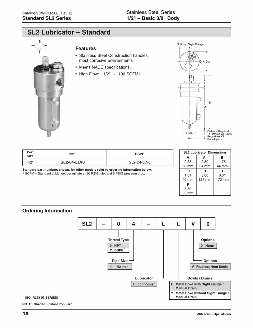
Bowls / Drains
L. Metal Bowl with Sight Gauge /Manual Drain
Y. Metal Bowl without Sight Gauge /Manual Drain
Features• Stainless Steel Construction handles
most corrosive environments.
• Meets NACE specifications.
• High Flow: 1/2" – 100 SCFM §
Stainless Steel Series1/2" – Basic 3/8" Body
Catalog 9CW-BH-260 (Rev. 2)
Standard SL2 Series
SL2 Lubricator – Standard
D
E
C
A Dia.
Optional Sight GaugeA1
B Dia. Distance RequiredTo Remove All BowlsRegardless OfDrain Option
F
SL2 Lubricator Dimensions
A A1 B2.38 2.50 1.75
60 mm 64 mm 44 mmC D E
1.81 5.00 6.8146 mm 127 mm 173 mm
F3.50
89 mm
Standard part numbers shown, for other models refer to ordering information below.§ SCFM = Standard cubic feet per minute at 90 PSIG inlet and 5 PSIG pressure drop.
Port NPT BSPPSize
1/2" SL2-04-LLV0 SL2-C4-LLV0
Ordering Information
NOTE: Shaded = “Most Popular”.
1 ISO, R228 (G SERIES)
SL2 – 0 4 – L L V 0
Options
V. Fluorocarbon Seals
Pipe Size
4. 1/2 Inch
Thread Type
0. NPTC. BSPP1
Lubricator
L. Economist
Options
0. None

Wilkerson Operations 19
0
1
2
3
4
5
0 10 20 30 40 50 60 70 80 90 100
Pre
ssu
re D
rop
- P
SIG
0
0 5 10 15 20 25 30 35 40 45
Flow - SCFM
Flow - dm /s
Pre
ssu
re D
rop
- b
ar
3
n
.1
.2
.3
Flow CharacteristicsSL2-04-LLV01/2 Inch Ports
25 PSIG 50 PSIG 75 PSIG 100 PSIGPrimary Pressure - PSIG
1.7 bar 3.4 bar 5.2 bar 6.9 barPrimary Pressure - bar
Stainless Steel SeriesAir Line Lubricators
Catalog 9CW-BH-260 (Rev. 2)
Technical Specifications – SL2
SL2 Filter Kits & AccessoriesDrain Kit – Manual Drain .................................................. SRP-96-008Liquid Level Sight and Gauge Kit .................................. SRP-96-026Pipe Nipple – 1/2" 316 Stainless Steel ............................ SRP-96-010Sight Dome / Metering Screw Kit ................................... SRP-96-025
SpecificationsBowl Capacity ................................................................... 4.0 OuncesPort Threads ........................................................................... 1/2 InchPressure & Temperature Ratings – 0 to 300 PSIG (0 to 20.7 bar)
40°F to 150°F (4°C to 66°C)Useful Retention .................................................................. 4 OuncesWeight ......................................................................... 1.9 lb. (0.85 kg)
Materials of ConstructionBody ....................................................................... 316 Stainless SteelBowl ....................................................................... 316 Stainless SteelDrain (Manual) ....................................................... 316 Stainless SteelSeals ................................................................................ FluorocarbonSight Dome ................................................................................... Nylon
Operation Air flowing through the unit goes through two paths.At low flow rates the majority of the air flows throughthe Venturi section (A). The rest of the air opens thecheck valve (C). The velocity of the air flowingthrough the Venturi section (A) creates a pressuredrop. This lower pressure allows the oil to be forcedfrom the reservoir through the pickup tube (B) andtravels up to the metering screw (D). The rate of oildelivery is then controlled by adjusting the meteringscrew (D). Oil flows past the metering screw (D) andforms a drop in the nozzle tube (E). As the oil dropsthrough the dome and back into the Venturi section(A), it is broken up into fine particles. It is then mixedwith the air flowing past the check valve (C) and iscarried downstream. As the air flow increases thecheck valve (C) will open more fully. This additionalflow will assure that the oil delivery rate will increaselinearly with the increase of air flow.
Technical Information
C
A
B
E
D

20 Wilkerson Operations
Catalog 9CW-BH-260 (Rev. 2)
Notes
Wilkerson Operations 21
Catalog 9CW-BH-260 (Rev. 2)
Offer of Sale
The items described in this document and other documents or descriptions provided by The Company, its subsidiaries and itsauthorized distributors, are hereby offered for sale at prices to be established by The Company, its subsidiaries and its authorizeddistributors. This offer and its acceptance by any customer (“Buyer”) shall be governed by all of the following Terms and Conditions.Buyer’s order for any such item, when communicated to The Company, its subsidiaries or an authorized distributor (“Seller”) verbally orin writing, shall constitute acceptance of this offer.
1. Terms and Conditions of Sale: All descriptions, quotations, proposals,offers, acknowledgments, acceptances and sales of Seller’s productsare subject to and shall be governed exclusively by the terms andconditions stated herein. Buyer’s acceptance of any offer to sell is limitedto these terms and conditions. Any terms or conditions in addition to, orinconsistent with those stated herein, proposed by Buyer in anyacceptance of an offer by Seller, are hereby objected to. No suchadditional, different or inconsistent terms and conditions shall becomepart of the contract between Buyer and Seller unless expressly acceptedin writing by Seller. Seller’s acceptance of any offer to purchase by Buyeris expressly conditional upon Buyer’s assent to all the terms andconditions stated herein, including any terms in addition to, or inconsistentwith those contained in Buyer’s offer. Acceptance of Seller’s productsshall in all events constitute such assent.2. Payment: Payment shall be made by Buyer net 30 days from the dateof delivery of the items purchased hereunder. Amounts not timely paidshall bear interest at the maximum rate permitted by law for each monthor portion thereof that the Buyer is late in making payment. Any claimsby Buyer for omissions or shortages in a shipment shall be waived unlessSeller receives notice thereof within 30 days after Buyer’s receipt of theshipment.3. Delivery: Unless otherwise provided on the face hereof, delivery shallbe made F.O.B. Seller’s plant. Regardless of the method of delivery,however, risk of loss shall pass to Buyer upon Seller’s delivery to acarrier. Any delivery dates shown are approximate only and Seller shallhave no liability for any delays in delivery.4. Warranty: Seller warrants that the items sold hereunder shall be freefrom defects in material or workmanship for a period of 18 months fromdate of shipment from Parker Hannifin Corporation. THIS WARRANTYCOMPRISES THE SOLE AND ENTIRE WARRANTY PERTAINING TOITEMS PROVIDED HEREUNDER. SELLER MAKES NO OTHERWARRANTY, GUARANTEE, OR REPRESENTATION OF ANY KINDWHATSOEVER. ALL OTHER WARRANTIES, INCLUDING BUT NOTLIMITED TO, MERCHANTABILITY AND FITNESS FOR PURPOSE,WHETHER EXPRESS, IMPLIED, OR ARISING BY OPERATION OFLAW, TRADE USAGE, OR COURSE OF DEALING ARE HEREBYDISCLAIMED.NOTWITHSTANDING THE FOREGOING, THERE ARE NOWARRANTIES WHATSOEVER ON ITEMS BUILT OR ACQUIREDWHOLLY OR PARTIALLY, TO BUYER’S DESIGN ORSPECIFICATIONS.5. Limitation of Remedy: SELLER’S LIABILITY ARISING FROM OR INANY WAY CONNECTED WITH THE ITEMS SOLD OR THIS CONTRACTSHALL BE LIMITED EXCLUSIVELY TO REPAIR OR REPLACEMENTOF THE ITEMS SOLD OR REFUND OF THE PURCHASE PRICE PAIDBY BUYER, AT SELLER’S SOLE OPTION. IN NO EVENT SHALLSELLER BE LIABLE FOR ANY INCIDENTAL, CONSEQUENTIAL ORSPECIAL DAMAGES OF ANY KIND OR NATURE WHATSOEVER,INCLUDING BUT NOT LIMITED TO LOST PROFITS ARISING FROMOR IN ANY WAY CONNECTED WITH THIS AGREEMENT OR ITEMSSOLD HEREUNDER, WHETHER ALLEGED TO ARISE FROM BREACHOF CONTRACT, EXPRESS OR IMPLIED WARRANTY, OR IN TORT,INCLUDING WITHOUT LIMITATION, NEGLIGENCE, FAILURE TOWARN OR STRICT LIABILITY.6. Changes, Reschedules and Cancellations: Buyer may request tomodify the designs or specifications for the items sold hereunder as wellas the quantities and delivery dates thereof, or may request to cancel allor part of this order, however, no such requested modification orcancellation shall become part of the contract between Buyer and Sellerunless accepted by Seller in a written amendment to this Agreement.Acceptance of any such requested modification or cancellation shall beat Seller’s discretion, and shall be upon such terms and conditions asSeller may require.7. Special Tooling: A tooling charge may be imposed for any specialtooling, including without limitations, dies, fixtures, molds and patterns,acquired to manufacture items sold pursuant to this contract. Suchspecial tooling shall be and remain Seller’s property notwithstandingpayment of any charges by Buyer. In no event will Buyer acquire anyinterest in apparatus belonging to Seller which is utilized in the manufactureof the items sold hereunder, even if such apparatus has been specially
converted or adapted for such manufacture and notwithstanding anycharges paid by Buyer. Unless otherwise agreed, Seller shall have theright to alter, discard or otherwise dispose of any special tooling or otherproperty in its sole discretion at any time.8. Buyer’s Property: Any designs, tools, patterns, materials, drawings,confidential information or equipment furnished by Buyer, or any otheritems which become Buyer’s property, may be considered obsolete andmay be destroyed by Seller after two (2) consecutive years have elapsedwithout Buyer placing an order for the items which are manufacturedusing such property. Seller shall not be responsible for any loss ordamage to such property while it is in Seller’s possession or control.9. Taxes: Unless otherwise indicated on the face hereof, all prices andcharges are exclusive of excise, sales, use, property, occupational or liketaxes which may be imposed by any taxing authority upon the manufacture,sale or delivery of the items sold hereunder. If any such taxes must bepaid by Seller or if Seller is liable for the collection of such tax, the amountthereof shall be in addition to the amounts for the items sold. Buyeragrees to pay all such taxes or to reimburse Seller therefore upon receiptof its invoice. If Buyer claims exemption from any sales, use or other taximposed by any taxing authority, Buyer shall save Seller harmless fromand against any such tax, together with any interest or penalties thereonwhich may be assessed if the items are held to be taxable.10. Indemnity For Infringement of Intellectual Property Rights:Seller shall have no liability for infringement of any patents, trademarks,copyrights, trade dress, trade secrets or similar rights except as providedin this Part 10. Seller will defend and indemnify Buyer against allegationsof infringement of U.S. patents, U.S. trademarks, copyrights, trade dressand trade secrets (hereinafter “Intellectual Property Rights”). Seller willdefend at its expense and will pay the cost of any settlement or damagesawarded in an action brought against Buyer based on an allegation thatan item sold pursuant to this contract infringes the Intellectual PropertyRights of a third party. Seller’s obligation to defend and indemnify Buyeris contingent on Buyer notifying Seller within ten (10) days after Buyerbecomes aware of such allegations of infringement, and Seller havingsole control over the defense of any allegations or actions including allnegotiations for settlement or compromise. If an item sold hereunder issubject to a claim that it infringes the Intellectual Property Rights of a thirdparty, Seller may, at its sole expense and option, procure for Buyer theright to continue using said item, replace or modify said item so as tomake it noninfringing, or offer to accept return of said item and return thepurchase price less a reasonable allowance for depreciation.Notwithstanding the foregoing, Seller shall have no liability for claims ofinfringement based on information provided by Buyer, or directed toitems delivered hereunder for which the designs are specified in wholeor part by Buyer, or infringements resulting from the modification,combination or use in a system of any item sold hereunder. The foregoingprovisions of this Part 10 shall constitute Seller’s sole and exclusiveliability and Buyer’s sole and exclusive remedy for infringement ofIntellectual Property Rights.If a claim is based on information provided by Buyer or if the design foran item delivered hereunder is specified in whole or in part by Buyer,Buyer shall defend and indemnify Seller for all costs, expenses orjudgements resulting from any claim that such item infringes any patent,trademark, copyright, trade dress, trade secret or any similar right.11. Force Majeure: Seller does not assume the risk of and shall not beliable for delay or failure to perform any of Seller’s obligations by reasonof circumstances beyond the reasonable control of Seller (hereinafter“Events of Force Majeure”). Events of Force Majeure shall includewithout limitation, accidents, acts of God, strikes or labor disputes, acts,laws, rules or regulations of any government or government agency,fires, floods, delays or failures in delivery of carriers or suppliers,shortages of materials and any other cause beyond Seller’s control.12. Entire Agreement/Governing Law: The terms and conditions setforth herein, together with any amendments, modifications and anydifferent terms or conditions expressly accepted by Seller in writing, shallconstitute the entire Agreement concerning the items sold, and there areno oral or other representations or agreements which pertain thereto.This Agreement shall be governed in all respects by the law of the Stateof Ohio. No actions arising out of sale of the items sold hereunder or thisAgreement may be brought by either party more than two (2) years afterthe cause of action accrues.

WilkersonPneumatic Division8676 E. M89P.O. Box 901Richland, MI 49083 USA
Catalog 9CW-BH-260 (Rev. 2) 4/03 10M IGS Printed in U.S.A.
Customer/Technical Service
Tel: (269) 629-2550Fax: (269) 629-2475Web site: www.wilkersoncorp.com