EXTENDED FINITE STRIP METHOD FOR PRISMATIC PLATE AND SHELL …
Građevinar 5/2013
411GRAĐEVINAR 65 (2013) 5, 411-422
UDK 624.073.012.45:519.6+513.3
Authors:
Prof. Dragan Milašinović, PhD. CEUniversity of Novi SadFaculty of Civil Engineering in [email protected]
Danica Goleš, PhD. CE University of Novi SadFaculty of Civil Engineering in [email protected]
Original scientific paper
Dragan Milašinović, Danica Goleš
Stability analysis of reinforced concrete prismatic shell structures
Stability analysis of prismatic reinforced concrete shells is presented in the paper. These structures are special shells for which both geometry and material properties can be considered as constant along the main direction, while only the loading distribution may vary. A semi-analytical harmonic coupled finite strip method (HCFSM) is used to solve the large deflection and post-buckling problems, or both actions simultaneously. This is particularly important for shells having large span-to-width ratios.
Key words:prismatic reinforced concrete shells, stability analysis, finite strip method
Izvorni znanstveni radDragan Milašinović, Danica Goleš
Analiza stabilnosti armiranobetonskih složenica
U radu je prikazana analiza stabilnosti armiranobetonskih složenica. Ove konstrukcije predstavljaju posebnu vrstu ljuski za koje se i geometrija i svojstva materijala mogu smatrati konstantnim duž glavnog pravca, dok samo raspodjela opterećenja može varirati. Poluanalitička harmonijski spojena metoda konačnih traka (HSMKT) primjenjuje se za rješavanje velikih progiba i problema poslije izvijanja ili na obje pojave istodobno. To je osobito važno za ljuske koje imaju veliki omjer raspona i širine
Ključne riječi:armiranobetonske složenice, analiza stabilnosti, metoda konačnih traka
Wissenschaftlicher OriginalbeitragDragan Milašinović, Danica Goleš
Stabilitätsanalyse prismatischer Flächentragwerke aus Stahlbeton
In dieser Arbeit ist die Stabilitätsanalyse prismatischer Flächentragwerke aus Stahlbeton dargestellt. Diese Tragwerke werden als eine besondere Art von Schalenkonstruktionen angesehen, bei denen die Geometrie und die Materialeigenschaften als konstant entlang einer Hauptrichtung angenommen werden können, während die Lastverteilung variieren kann. Die halbanalytische Methode harmonisch verbundener finiter Streifen wird angewandt, um große Verformungen und das Nachbeulverhalten, oder beide Erscheinungen zugleich, zu berücksichtigen. Dies ist von Bedeutung insbesondere für Schalentragwerke großen Verhältnisses zwischen Reichweite und Breite.
Schlüsselwörter:prismatische Flächentragwerke aus Stahlbeton, Stabilitätsanalyse, Finite-Streifen-Methodet
Stability analysis of reinforced concrete prismatic shell structures
Primljen / Received: 19.1.2013.
Ispravljen / Corrected: 8.5.2013.
Prihvaćen / Accepted: 15.5.2013.
Dostupno online / Available online: 10.6.2013.
Građevinar 5/2013
412 GRAĐEVINAR 65 (2013) 5, 411-422
Dragan Milašinović, Danica Goleš
local modes, only the terms that are nonlinear in w are relevant. Nonlinear geometric relations are accepted in the following form:
(1)
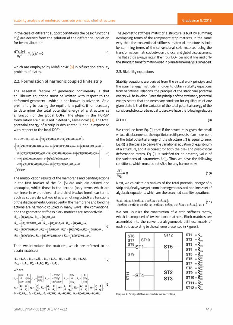
where u, v and w are the displacements of an arbitrary point in the x, y and z direction, while u0, v0 and w0 are the displacements of the point in the middle plane, at z=0. Nonlinear contributions added in Eq. (1) can be considerably significant in the kind of problem considered in this study, wherein u and w displacements of component strips generally can have similar magnitudes due to large movements of junction nodal lines. In the FSM, which combines elements of the classical Ritz and the finite element methods, the general form of the displacement function can be written as a product of polynomials and trigonometric functions
(2)
where Ym(y) are the basic functions in the y-direction and Nk(x) are the interpolation functions in the x-direction. We define the local Degrees Of Freedom (DOFs) as the displacements and rotation of a nodal line (DOFs=4), as shown in Figure 1. The DOFs are also known as generalized coordinates. The following approximate functions are used for the simply supported flat shell strip:
(3)
Figure 1. Typical flat shell strip
1. Introduction
The design of reinforced concrete folded plate structures has two aspects, the one concerns codes and the other computations. Structural codes used throughout the world are now based on the semi-probabilistic limit-state approach. In many instances, an efficient design of reinforced concrete prismatic shells may be based on the assumption of nonlinear response to loading, whether it be of the geometric kind, or of the combined geometric-physical kind. With the modern trend of employing thin plates in shell structures made of composite reinforced concrete materials, the prediction of geometric nonlinear elastic behavior has become increasingly important.The development of computer techniques and software enables analysis of mathematical models of structures that are very close to real-life structures. The finite strip method (FSM) has been used for solving numerous problems in continuum mechanics [1-3]. This method, first developed in the context of thin plate bending analysis, is a semi-analytical finite element procedure. In the linear elastic analysis, it takes advantage of orthogonal properties of harmonic functions in the stiffness matrix formulation to yield a block diagonal stiffness matrix, thereby decomposing a two dimensional problem into several independent sub problems, each corresponding to a one dimensional problem. Further advantages of the method lie in the possibility of modeling using a small number of harmonics. The FSM is one of many procedures that can be used to analyze large deflection problems and post-overall-buckling behavior of prismatic shell structures [4-6]. However, in the case of the geometric stiffness matrix computation, integral expressions contain products of trigonometric functions with higher-order exponents, and therefore the orthogonal characteristics are no longer valid. All harmonics are coupled, and the stiffness matrix order and bandwidth are proportional to the number of harmonics used. Originally proposed and implemented in the context of a special sequential software package [3], the HCFSM formulation has since been frequently used and validated [7, 8]. The remainder of this paper is organized as follows: An overview of the finite-strip geometric nonlinear analysis is presented in Section 2. In order to emphasize the effects of geometrical nonlinearity to longer and shorter shells, prismatic shells of the same cross-section are analyzed in Section 3. Illustrative numerical results of real reinforced-concrete folded plate structures are presented in Section 4, which is followed by conclusions given in Section 5.
2. Harmonic coupled finite strip stability analysis
2.1. Nonlinear geometric relations included in finite strip
Nonlinear geometric relations in the finite strip can be written as a combination of the plane elasticity and the Kirchhoff-Love plate theory. However, not all nonlinear terms are of the same magnitude. If the plate assembly is long, nonlinear terms involving the v0 component are negligible, and in many applications the terms containing the u0 component may also be neglected. In
Građevinar 5/2013
413GRAĐEVINAR 65 (2013) 5, 411-422
Stability analysis of reinforced concrete prismatic shell structures
The geometric stiffness matrix of a structure is built by summing overlapping terms of the component strip matrices, in the same way that the conventional stiffness matrix of structure is built by summing terms of the conventional strip matrices using the transformation matrices between the local and global displacement. The flat strips always retain their four DOF per nodal line, and only the standard transformation used in plane frame analysis is needed.
2.3. Stability equations
Stability equations are derived from the virtual work principle and the strain energy methods. In order to obtain stability equations from variational relations, the principle of the stationary potential energy will be invoked. Since the principle of the stationary potential energy states that the necessary condition for equilibrium of any given state is that the variation of the total potential energy of the considered structure be equal to zero, we have the following relation:
dP = 0 (9)
We conclude from Eq. (9) that, if the structure is given the small virtual displacements, the equilibrium still persists if an increment of the total potential energy of the structure dP is equal to zero. Eq. (9) is the basis to derive the variational equation of equilibrium of a structure, and it is correct for both the pre- and post-critical deformation states. Eq. (9) is satisfied for an arbitrary value of the variations of parameters dqT
m. Thus we have the following conditions, which must be satisfied for any harmonic m:
= 0 (10)
Next, we calculate derivatives of the total potential energy of a strip and, finally, we get a non-homogeneous and nonlinear set of algebraic equations, which are the searched stability equations.
(11)
We can visualize the construction of a strip stiffness matrix, which is composed of twelve block matrices. Block matrices are assembled into the conventional/geometric stiffness matrix of each strip according to the scheme presented in Figure 2.
Figure 2. Strip stiffness matrix assembling
In the case of different support conditions the basic functions Y(y) are derived from the solution of the differential equation for beam vibration:
Za drugačije uvjete (4)
which are employed by Milašinović [6] in bifurcation stability problem of plates.
2.2. Formulation of harmonic coupled finite strip
The essential feature of geometric nonlinearity is that equilibrium equations must be written with respect to the deformed geometry – which is not known in advance. As a preliminary to tracing the equilibrium paths, it is necessary to determine the total potential energy of a structure as a function of the global DOFs. The steps in the HCFSM formulation are discussed in detail by Milašinović [3]. The total potential energy of a strip is designated P and is expressed with respect to the local DOFs.
(5)
The multiplication results of the membrane and bending actions in the first bracket of the Eq. (5) are uniquely defined and uncoupled, whilst those in the second [only terms which are nonlinear in w are relevant] and third bracket {nonlinear terms such as square derivatives of u0 are not neglected} are functions of the displacements. Consequently, the membrane and bending actions are harmonic coupled in many ways. The conventional and the geometric stiffness block matrices are, respectively:
(6)
Then we introduce the matrices, which are referred to as strain matrices:
(7)
where:
(8)
Građevinar 5/2013
414 GRAĐEVINAR 65 (2013) 5, 411-422
Dragan Milašinović, Danica Goleš
2.4. Solution of nonlinear stability equations
For equilibrium, the principle of stationary potential energy of structure requires that
(12)
where P is a function of the displacements q. R represent the gradient or residual force vector, which is generally nonzero for some approximate displacement vector q0 (the subscript 0 denotes an old value). It is assumed that a better approximation is given by
(13)
where subscript n denotes a new value. Taylor’s expansion of Eq. (12) yields:
(14)
where is the matrix of second partial derivatives of P calculated at q0 (i.e. the tangent stiffness matrix of structure (TSMS) or Hessian matrix). Setting Eq. (14) to zero and considering only linear terms in d0 gives the standard expression for the Newton-Raphson iteration
(15)
Using this approach, a further iteration yields:
(16)
where for qn. It is obvious from the Newton-Raphson method that TSMS has to be inverted and updated in each iteration step. The process is repeated to establish convergence criteria, i.e.
(17)
where N is the total number of nodal lines in the decomposed structure while rt determines the number of iterations. This criterion indicates that convergence occurs when the norm of the residual forces becomes less than some pre-defined value e.
In addition, the blocks of the conventional and geometric TSMS are:
(18)
(19)
Comparing these expressions with Eq. (11), it is apparent that the conventional stiffness matrix remains unchanged, while the geometric stiffness matrix becomes symmetrical.
2.5. Formation of stiffness matrix blocks
As outlined in Section 2.2, the developed HCFSM approach is used to derive stability equations. The approach involves a number of symbolic computations. Especially, the symbolic integration of energy expressions of each strip may require a lot of computational time and memory resources when a large number of series terms are used. For a more efficient application of the HCFSM formulation the values of integrals that are used to compute geometric stiffness block matrices of each strip may be computed once, independent of a particular strip length, and stored in memory to be used later [3]. The elements of the property matrices A and D for the orthotropic plates are:
(20)
2.6. Static buckling
The loss of stability of static equilibrium state of structures subjected to conservative loads is generally known as static buckling of structures. For conservative systems, the minimum total potential energy principle can be used to test the stability of a structure (static equilibriums are extremes of the total potential energy). The Hessian with respect to the local DOFs is denoted as the tangent stiffness matrix of each strip, i.e.
(21)
The stability of equilibrium states of conservative systems built by HCFSM can be assessed by looking at the eigenvalues of TSMS with n nodal lines, which are all real, since the tangent stiffness matrix of the strip is a symmetric matrix. Let λi denote the ith eigenvalue of
(22)
Based on theorems presented by Lagrange-Dirichlet and Lyapunov [9, 10], it can be concluded that an equilibrium state is stable if all λi>0, while an equilibrium state is unstable if one or more λi<0. If along a load-path at some equilibrium state one or more λi=0, this equilibrium state is denoted as a critical state. Static buckling refers in general to cases where, starting from some stable state, a critical state is reached along the load-path.Furthermore, without loss of generality, it will also be presumed dependent on a single scalar P which determines the magnitude (or distribution) of external conservative loads Q exerted on the structure.

Građevinar 5/2013
415
Stability analysis of reinforced concrete prismatic shell structures
GRAĐEVINAR 65 (2013) 5, 411-422
The critical state and corresponding load are denoted by
(23)
respectively. At a critical state, it follows that
(24)
where the column z denotes the buckling mode. In general, Eq. (24) constitutes a nonlinear eigenvalue problem, since K(in general) depends in a nonlinear fashion on the global DOFs qi, which in turn may depend in a nonlinear fashion on the load P, as defined by the equilibrium equations, Eq. (11).In general, Eq. (24) is solved by solving Eq. (11) for a varying load P with for example some sort of a numerical path-following routine (see Ref. [3]), while simultaneously tracking the eigenvalues of TSMS given by Eq. (22). The buckling occurs where the matrix becomes singular.
2.7. Membrane forces and bending moments of harmonic coupled finite strip
Three force components (Nx=tσx, Ny=tσy, Nxy=tσxy) and three moment components (Mx, My, Mxy) are related to strains through material properties of the strip. In the present formulation, the more general case of orthotropic properties is assumed.
(25)
where: (26)
Eqs. (25) can be rewritten as follows:
(27)
Multiplication yields:
(28)
(28)
The linear vectors umN̂ and wmM̂ are uniquely defined. The nonlinear vector wmN is entirely consistent with the von Karman approach, which ignores nonlinear terms in strain-displacement relations for bending stresses, but not for membrane stresses. The Green-Lagrange approach also yields the nonlinear vector u
umN .
3. The effects of geometrical nonlinearity on longer and shorter shells
Prismatic shells of a typical cross-section, shown in Figure 3, were analyzed for different span lengths of 70, 74, 78, 82, 86, 90 and 100 m, and a close correspondence with the linear analysis results obtained by Cheung and Tam [1] is observed. In order to emphasize the effects of geometrical nonlinearity on longer and shorter shells, folded plates of the same cross-section are analyzed again in this paper for the distributed load which is 1000 times higher than the one referred to in [1].
Figure 3. Prismatic shell sectional dimensions and its strip idealization
Distributed loads in Z direction are divided into a total of ten increments. Because the deformation is symmetrical about the longitudinal central line, only half the structure, in addition to this central line, is analyzed. The Young’s elasticity modulus for concrete E=35.820.000 kN/m2, and the zero Poisson’s ratio, are taken in all examples. Comparative analysis is done for linear, von Karman, and Green-Lagrange predictions.The corresponding load-path in terms of the TSMS eigenvalue is depicted in Figure 4. To illustrate the static equilibrium in the context of stability, the load-part curves which correspond to stable equilibrium states are plotted with a solid line, while the load-part curves which correspond to unstable equilibrium states are plotted with a dashed line. The analysis of the influence of load on TSMS eigenvalue was demonstrated to all span lengths and different number of series terms adopted in the computations. For shorter shell (70 m) the stability regions were observed for the both von Karman and the Green-Lagrange predictions under all load-parts. It was stated that the load and span length have a serious influence on the equilibrium state. When the span length increases a drop of the TSMS eigenvalue can be observed in the Green-Lagrange prediction. For small load values on the longer shell (90 m), the instability region was observed to expand, whether only one or several series terms are used. However, when load

Građevinar 5/2013
416 GRAĐEVINAR 65 (2013) 5, 411-422
Dragan Milašinović, Danica Goleš
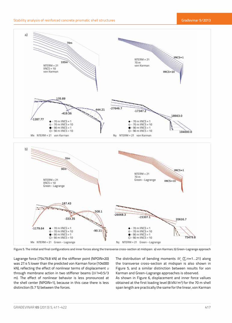
increases the rise of the TSMS eigenvalue is observed, and instability regions vanish. Using geometric relations of the nonlinear prismatic shell theory in the frame of HCFSM, we determined large displacements (w, u and j), inner forces and moments for both von Karman and Green-Lagrange approaches, taking into account various shell span lengths and load-paths. The initial and transient shell configurations plotted in Figure 5, in
which all displacements are presented, show the importance of the length and change of load in both predictions. In Figure 5, distribution of the membrane force Ny (∑m=1…21) along the transverse cross-section at midspan is shown at load levels of 8kN/m2 (IINCS=1) and 80kN/m2 (IINCS=10) respectively, for both approaches. The effect of nonlinear behavior is very prominent in the difference between the results at the last loading level for the 90m shell span length. The attained Green-
Figure 4. Variation of TSMS eigenvalue with load intensity for inputs with different series terms
Građevinar 5/2013
417
Stability analysis of reinforced concrete prismatic shell structures
GRAĐEVINAR 65 (2013) 5, 411-422
Lagrange force (75479.8 kN) at the stiffener point (NPOIN=20) was 27.4 % lower than the predicted von Karman force (104000 kN), reflecting the effect of nonlinear terms of displacement u
through membrane action in two stiffener beams (b/h=0.5/3 m). The effect of nonlinear behavior is less pronounced at the shell center (NPOIN=1), because in this case there is less distinction (5.7 %) between the forces.
The distribution of bending moments Mx (∑m=1…21) along the transverse cross-section at midspan is also shown in Figure 5, and a similar distinction between results for von Karman and Green-Lagrange approaches is observed.As shown in Figure 6, displacement and inner force vallues obtained at the first loading level (8 kN/m2) for the 70 m shell span length are practically the same for the linear, von Karman
Figure 5. The initial and final configurations and inner forces along the transverse cross-section at midspan: a) von Karman; b) Green-Lagrange approach

Građevinar 5/2013
418 GRAĐEVINAR 65 (2013) 5, 411-422
Dragan Milašinović, Danica Goleš
Figure 6. Load-displacement (w, u, and j) and load-membrane force Ny curves with instability regions
Građevinar 5/2013
419
Stability analysis of reinforced concrete prismatic shell structures
GRAĐEVINAR 65 (2013) 5, 411-422
and Green-Lagrange predictions, because at this loading level the shell exhibits no significant geometric nonlinear behavior. We analyzed equilibrium paths and we found all stability regions for this shell span length, although the values of central displacement w change the sign. However, it is not the case for the larger shell span lengths.
For the 90 m shell span length in the Green-Lagrange computation, four instability regions are observed with only one series term included, and two with 21 harmonics used. In instability regions the displacement u and rotation j reached extreme values at the stiffener points. Then they change the sign and the shell suddenly leaps to a stable state of
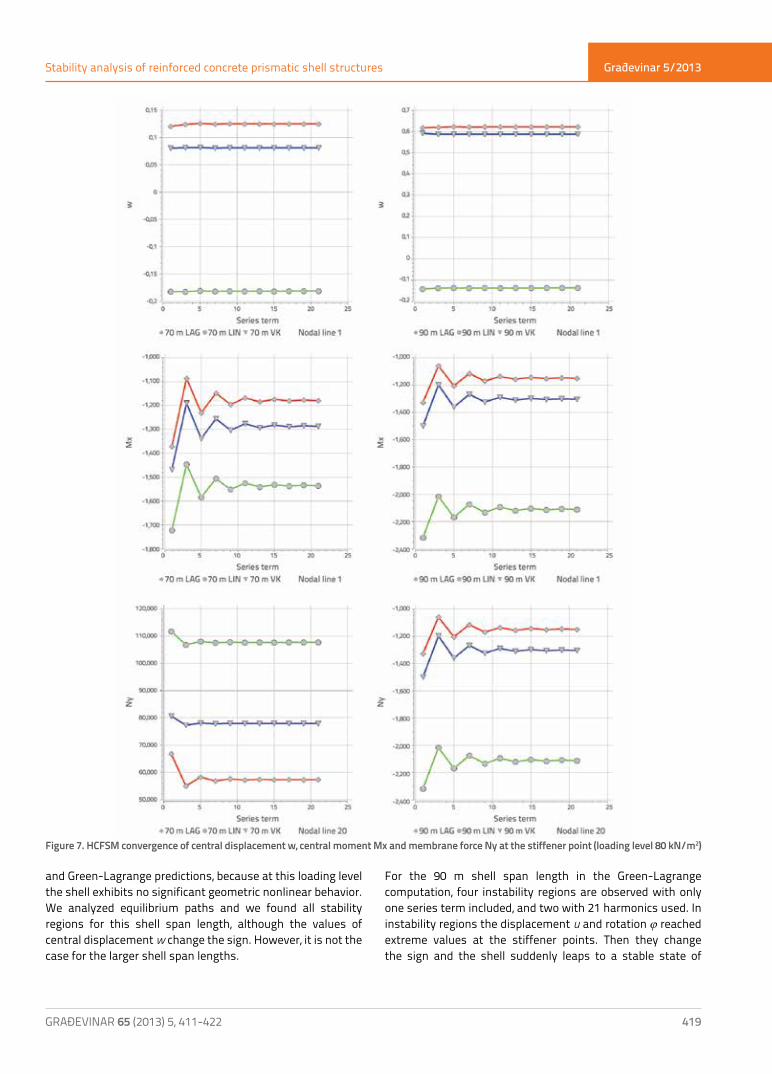
Figure 7. HCFSM convergence of central displacement w, central moment Mx and membrane force Ny at the stiffener point (loading level 80 kN/m2)
Građevinar 5/2013
420 GRAĐEVINAR 65 (2013) 5, 411-422
Dragan Milašinović, Danica Goleš
equilibrium under higher load levels. Of course, these regions are in connection with buckling. However, this problem is different from the buckling of a plate under an axial load since it involves a very important membrane behavior in the pre-buckling configurations and an important membrane-bending coupling (and torsion) in the post-buckling range. The shell buckles after reaching extreme displacement values at the stiffener points.Figure 7 illustrates the extremely rapid monotonic convergences of central displacements w for 70 m and 90 m shell span lengths. It is apparent that only a few series terms are required for the displacements to converge to the exact answer. The rate of convergence for central moments Mx, and membrane forces Ny at the stiffener point was also analyzed at the last loading level (80 kN/m2). It is apparent that 21 series terms (summing 21 harmonics, i.e., 11 off-terms only) are required for the moments to converge to the exact answer, and 9 series terms for the forces. The convergence is non-monotonic for both inner forces.
4. Application to real reinforced concrete folded plate structures
Feasible reinforced concrete folded plate structures (RCFPS) of different span lengths and various cross-sections were analyzed in detail by Goleš [11]. On the basis of these results, here we will estimate the importance of effects of geometrical nonlinearity on real shells with realistic load, and assess the magnitude of error that results from the assumption of small displacements of these structures.
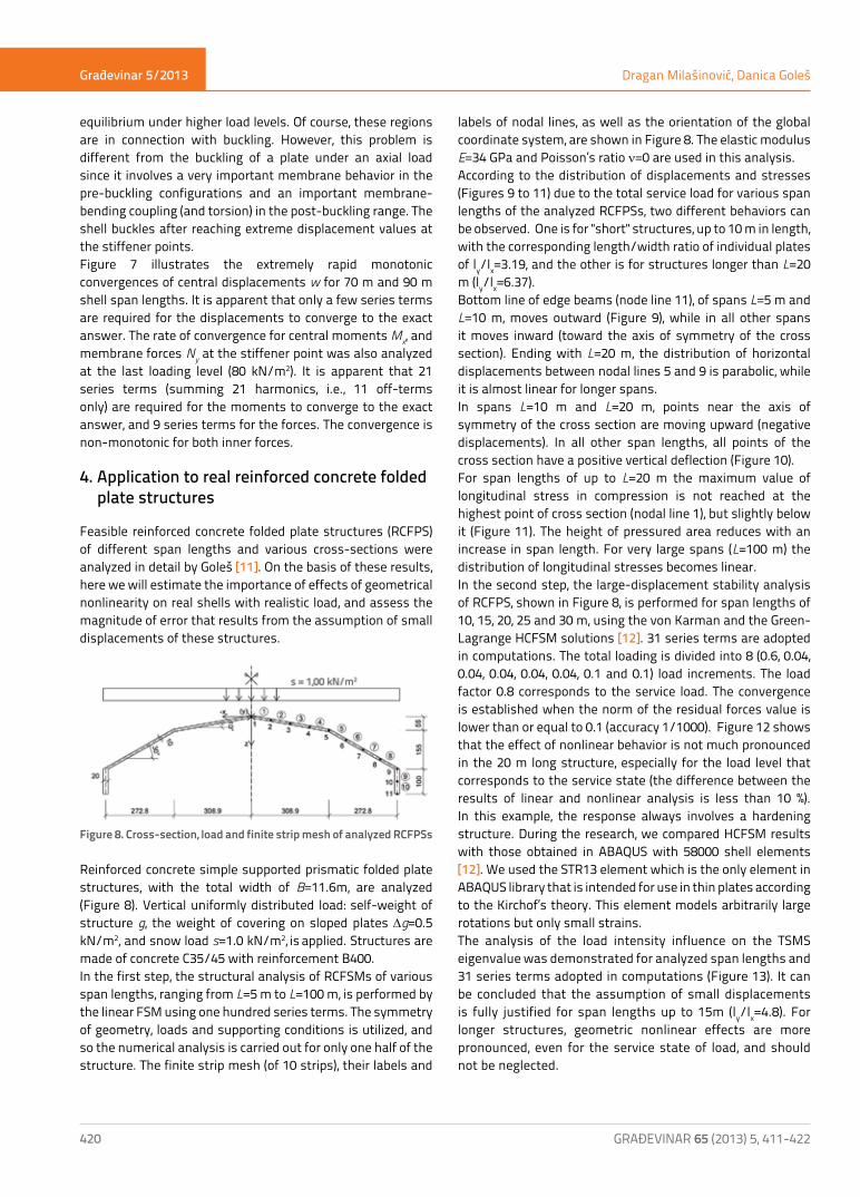
Figure 8. Cross-section, load and finite strip mesh of analyzed RCFPSs
Reinforced concrete simple supported prismatic folded plate structures, with the total width of B=11.6m, are analyzed (Figure 8). Vertical uniformly distributed load: self-weight of structure g, the weight of covering on sloped plates Dg=0.5 kN/m2, and snow load s=1.0 kN/m2, is applied. Structures are made of concrete C35/45 with reinforcement B400.In the first step, the structural analysis of RCFSMs of various span lengths, ranging from L=5 m to L=100 m, is performed by the linear FSM using one hundred series terms. The symmetry of geometry, loads and supporting conditions is utilized, and so the numerical analysis is carried out for only one half of the structure. The finite strip mesh (of 10 strips), their labels and
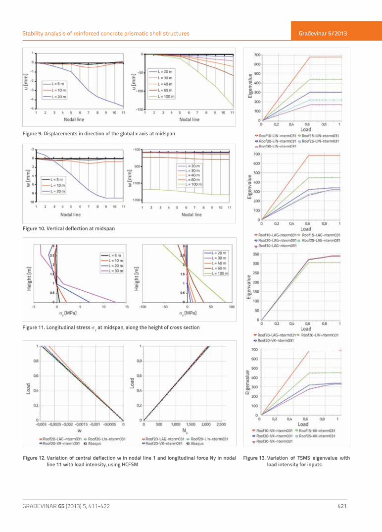
labels of nodal lines, as well as the orientation of the global coordinate system, are shown in Figure 8. The elastic modulus E=34 GPa and Poisson’s ratio n=0 are used in this analysis.According to the distribution of displacements and stresses (Figures 9 to 11) due to the total service load for various span lengths of the analyzed RCFPSs, two different behaviors can be observed. One is for "short" structures, up to 10 m in length, with the corresponding length/width ratio of individual plates of ly/lx=3.19, and the other is for structures longer than L=20 m (ly/lx=6.37).Bottom line of edge beams (node line 11), of spans L=5 m and L=10 m, moves outward (Figure 9), while in all other spans it moves inward (toward the axis of symmetry of the cross section). Ending with L=20 m, the distribution of horizontal displacements between nodal lines 5 and 9 is parabolic, while it is almost linear for longer spans.In spans L=10 m and L=20 m, points near the axis of symmetry of the cross section are moving upward (negative displacements). In all other span lengths, all points of the cross section have a positive vertical deflection (Figure 10).For span lengths of up to L=20 m the maximum value of longitudinal stress in compression is not reached at the highest point of cross section (nodal line 1), but slightly below it (Figure 11). The height of pressured area reduces with an increase in span length. For very large spans (L=100 m) the distribution of longitudinal stresses becomes linear.In the second step, the large-displacement stability analysis of RCFPS, shown in Figure 8, is performed for span lengths of 10, 15, 20, 25 and 30 m, using the von Karman and the Green-Lagrange HCFSM solutions [12]. 31 series terms are adopted in computations. The total loading is divided into 8 (0.6, 0.04, 0.04, 0.04, 0.04, 0.04, 0.1 and 0.1) load increments. The load factor 0.8 corresponds to the service load. The convergence is established when the norm of the residual forces value is lower than or equal to 0.1 (accuracy 1/1000). Figure 12 shows that the effect of nonlinear behavior is not much pronounced in the 20 m long structure, especially for the load level that corresponds to the service state (the difference between the results of linear and nonlinear analysis is less than 10 %). In this example, the response always involves a hardening structure. During the research, we compared HCFSM results with those obtained in ABAQUS with 58000 shell elements [12]. We used the STR13 element which is the only element in ABAQUS library that is intended for use in thin plates according to the Kirchof’s theory. This element models arbitrarily large rotations but only small strains.The analysis of the load intensity influence on the TSMS eigenvalue was demonstrated for analyzed span lengths and 31 series terms adopted in computations (Figure 13). It can be concluded that the assumption of small displacements is fully justified for span lengths up to 15m (ly/lx=4.8). For longer structures, geometric nonlinear effects are more pronounced, even for the service state of load, and should not be neglected.
Građevinar 5/2013
421
Stability analysis of reinforced concrete prismatic shell structures
GRAĐEVINAR 65 (2013) 5, 411-422
Figure 9. Displacements in direction of the global x axis at midspan
Figure 10. Vertical deflection at midspan
Figure 11. Longitudinal stress σy at midspan, along the height of cross section
Figure 12. Variation of central deflection w in nodal line 1 and longitudinal force Ny in nodal line 11 with load intensity, using HCFSM
Figure 13. Variation of TSMS eigenvalue with load intensity for inputs
Građevinar 5/2013
422 GRAĐEVINAR 65 (2013) 5, 411-422
Dragan Milašinović, Danica Goleš
5. Conclusion
Two HCFSM formulations using von Karman and Green-Lagrange geometric relations, for prismatic shell analysis with large geometric nonlinearities, are presented in this paper. The instability of panels, columns, box bridges, or any type of prismatic shells having large span-to-width ratios, can be induced by any kind of load: longitudinal, compressive, or even tensile, by bending, and also by torsional moment. In this respect, a uniform criterion for instability of any kind of shell structures, whose modeling can be found within the HCFSM framework, is proposed. It is shown that the stability of equilibrium states of prismatic shells can be assessed by looking at eigenvalues λi of TSMS, which are all real since the tangent stiffness matrix of the strips are symmetric matrices. An equilibrium state is stable if all λi>0, while an equilibrium state is unstable if one or more λ<0. If along a load-path at some equilibrium state one or more λi=0, this equilibrium state is denoted as a critical state.According to results of analyses made for feasible reinforced concrete folded plate structures, some conclusions about justifiability of the assumption of small displacements can be made even on the basis of linear analysis. Two different behaviors of structures are observed - for "short" structures
REFERENCES[1] Cheung, Y.K., Tham, L.G.: Finite strip method, CRC Press LLC,
1998.[2] Loo, Y.C., Cusens, A.R.: The finite strip method in bridge
engineering, Alden Press Oxford London and Northampton, 1978.
[3] Milašinović, D.D.: The finite strip method in computational mechanics, Faculties of Civil Engineering: University of Novi Sad, Technical University of Budapest and University of Belgrade, Subotica, Budapest, Belgrade, 1997.
[4] Dawe, D.J., Lam, S.S.E., Azizian, Z.G.: Non-linear finite strip analysis of rectangular laminates under end shortening, using classical plate theory, International Journal for Numerical Methods in Engineering, 35(5), pp. 1087-1110, 1992.
[5] Milašinović, D.: Metod konačnih traka u nelinearnoj analizi A/B konstrukcija, Jugoslovenski časopis za inženjersko modeliranje, 1(2-4), pp. 101-109, 1988.
[6] Milašinović, D.: Bifurkaciona stabilnost metodom konačnih traka, Građevinar, 10, str. 415-417, 1985.
[7] Milašinović, D.D.: Geometric non-linear analysis of thin plate structures using the harmonic coupled finite strip method, Thin-Walled Structures, 49(2), pp. 280-290, 2011.
[8] Rakić, P.S., Milašinović, D.D., Živanov, Ž., Suvajdžin, Z., Nikolić, M., Hajduković, M.: MPI-CUDA parallelization of a finite-strip program for geometric nonlinear analysis: A hybrid approach, Advances in Engineering Software, 42(5), pp. 273-285, 2011.
[9] Bažant, Z.P., Cedolin, L.: Stability of Structures: Elastic, Inelastic, Fracture, and Damage Theories, Oxford University Press, Oxford, 1991.
[10] Pignataro, M., Rizzi, N., Luongo, A.: Stability, bifurcation and postcritical bahaviour of elastic structures, Elsevier Science Publishers, Amsterdam, 1991.
[11] Goleš, D.: Reološko-dinamička analiza armiranobetonskih poliedarskih ljuski, doktorska disertacija, Građevinski fakultet Subotica, Univerzitet u Novom Sadu, 2012.
[12] Milašinović, D.D., Goleš, D., Borković, A., Kukaras, D., Landović, A., Živanov, Z., Rakić, P.: Rheological-Dynamical Limit Analysis of Reinforced Concrete Folded Plate Structures using the Harmonic Coupled Finite-Strip Method, in B.H.V. Topping, (Editor), Proceedings of the Eleventh International Conference on Computational Structures Technology, Civil-Comp Press, Stirlingshire, UK, Paper 158, 2012. doi: 10.4203/ccp.99.158.
and "long" structures. The border between these two behaviors denotes the border between structures in which the linear analysis gives results of sufficient accuracy, and structures whose nonlinear behavior can not be neglected. This is confirmed by means of the geometric nonlinear analysis. It is also shown that, for realistic folded plate structures under service load, geometric nonlinear effects are pronounced for large spans only.The HCFSM formulation has proven to be appropriate for the stability analysis of prismatic shell structures, owing to inexpensiveness, accuracy and reliability of von Karman and Green-Lagrange predictions.
Acknowledgements
Results reported in this paper were obtained in the scope of the following two research projects: ON 174027 "Computational Mechanics in Structural Engineering", and TR 36017 "Utilization of Byproducts and Recycled Waste Materials in Concrete Composites in the Scope of Sustainable Construction Development in Serbia: Investigation and Environmental Assessment of Possible Applications", which benefited from the support of the Ministry for Science and Technology, Republic of Serbia. This support is gratefully acknowledged.