TACTIX Owner’s Manual CHARLIE...TACTIX Owner’s Manual CHARLIE ... 8

1
ST-B SERIESOwner’s Manual
Before operating the unit, please read this manual throughly and retain it for future reference.

MISSION STATEMENT
Committed to Excellence
ZAPCO is dedicated to the pursuit of audio fidelity. Our prime objectives are todesign and manufacture audio products of unsurpassed quality, to provide
unparalleled support and service for these products and to conduct businessin a manner that will enhance the quality of life for all involved.
Experience(Knowledge from doing)
There is absolutely no substitute for experience; that is a simple fact of life.Another simple fact is that ZAPCO has, for over forty years, been the leader in
defining quality standards for the car audio industry.These years of experience have led to a thorough understanding of the
challenges that are unique to the world of car audio. ZAPCO's relentless questfor sonic purity consistently yields imaginative designs that utilize the most innovative technologies. The resulting products set the criteria by which all
others in the industry are judged.

1
Table of Contents
Before you start your installation ................................................................... 2Planning your power connections .................................................................. 3
Wire size ................................................................................................. 4Mounting your ST-B amplifier ......................................................................... 5Inputs and Controls ......................................................................................... 6
ST-2B Input Ends ..................................................................................... 6ST-4B Input Ends ..................................................................................... 7ST-1B Input Ends ..................................................................................... 8
Speaker Wiring of the ST-B Amplifiers ............................................................ 9ST-2B Speaker Wiring ............................................................................. 9ST-4B Speaker Wiring ............................................................................. 11ST-1B Speaker Wiring ............................................................................. 13
Technical Specifications .................................................................................. 13
The ST-B Series. Great sound for every day use.
ZAPCO has a reputation for sound reproduction and quality that is unsurpassed.It is our dedication to sonic purity and our passion for performance that builtZapco's reputation. With all the new amps coming into the market, not onehas been any threat to Zapco's standing as the premium amp and processorline. Just check the audio competition scene and the audio forums.
But not everyone wants to compete. The question was this: could Zapco putit's 40-years of audio experience to work to develop an amp for every-dayuse? An amp that all can afford but that will stay true to the Zapco heritage forsound and reliability? Absolutely! We can and we have! The new ST-B ampsare a testament to the fact that you can build a quality product with greatsound in an amplifier for every day use.
With the Studio-B amplifiers Zapco brings the sound quality and reliability thatbuilt the Zapco legend to an amplifier that everyone can afford.
2
Before you start your installation
ZAPCO highly recommends that a fuse or circuit breaker be placed within 18"of the battery. Although you will add a fuse or fuse block near the amplifier itis still a possibility that a pinched power wire between the component fuseand the battery could result in a short, or even a fire. The protection deviceshould be placed where it can be accessed easily and all wiring should berouted safely and correctly according to the following guidelines:
Do not run wiring close to hot or spinning objects.
Always use wire grommets when routing wire through the firewall or anyother metal panels.
Make sure that the potential for pinched wiring is avoided by routing all wiresaway from moving hinges and seats. This also includes brake, gas and clutchpedals, hood and trunk hinges, etc.
Continuous exposure to excessive sound pressure levels may cause permanenthearing loss. ZAPCO strongly advises that you use common sense when settingvolume levels. If you experience ringing in the ears, it could cause permanenthearing damage!
When connecting our amplifiers to pre-wired stock speakers, care must betaken that there are no common connections between left and right speakerwires, i.e. two or more speakers using the same ground connection (very common in pre-85 cars), as this will cause the amplifier to go into immediateprotection or may cause damage to the amplifier. Output connections are notcommon chassis ground. Please follow the hookup instructions in this owner'smanual. Any questions should be directed to your local ZAPCO dealer.

3
Planning your power connections
The power end plates of the Zapco ST-B amplifiers carry the power connectionsand the speaker connections and vary somewhat by the number of channels.For example, the power end of the ST-4B below has (of course) speaker connections for four channels. The ST-B amps all have on-board fuses and thefuse rating as printed above the fuses. The main 12-volt power input, the 12-volt turn-on wire, and the main Ground connection are common to both models.
• The main power input must be connected the vehicle battery's positive(+) terminal, and a main system fuse should be placed close to the battery
• The main ground or negative connection must be securely attached tobare metal at the vehicle frame, or other heavy chassis component witha direct connection to the frame
Note: Seat bolts and seat belt bolts are NOT good ground points• The terminal between the main power and ground is the +12 turn-on
input and can be connected to the head unit turn-on output wire.If none is available it can be connected to an accessory (ACC) terminal.You should avoid using any ignition-on (IGN) wire, as they can be noisy
Turn-on trigger wire
+12 volt at Battery positive terminal Ground to chassis

4
Some words about Power and Ground
Note: The second most common cause of underperforming amplifiers is insufficient power current or a pour power connection. The most common cause of underperforming amplifiers isinsufficient ground current or a bad ground connection.
12-volt current: Battery Power works only if it travels in a complete circuit fromthe battery positive terminal to the battery negative terminal. Main powerinput, of course, is attached to the battery positive terminal. Ground current isreturned to the battery through the chassis to the to the point where the batteryis grounded.
The current available for your amplifier to use to produce power will be restricted by the smallest gauge of wire in the circuit and by the weakest physicalconnection in the circuit.
Wire Size
It's often surprising how many people will obsess about signal wire but routinelyprovide the amplifier with only a fraction of the current it needs to do its job.The most common wire gauge used in car audio is 10-gauge, and the mostcommon location for amplifiers is in the trunk.
Wire Sizing Chart
4 ft 7 ft 10 ft 13 ft 16 ft 19 ft 22 ft 28 ft 0-20 amps 14 12 12 10 10 8 8 820-35 amps 12 10 8 8 6 6 6 435-50 amps 10 8 8 6 6 4 4 450-60 amps 8 8 6 4 4 4 4 265-85 amps 6 6 4 4 2 2 2 085 -105amps 6 6 4 2 2 2 2 0105-125 amps 4 4 4 2 2 0 0 0125-150 amps 2 2 2 2 0 0 0 0
Let's look at a fairly small system. If you use a 50 watt/ch amp (25 amps)for the highs and a 100 watt/ch amp (40 amps) for the woofers, you need atleast a 4-gauge and maybe a 2-Guage wire to provide 65 amps at the trunk.Anything less and your car won't go boom. It'll just go Blap!
Length of Run

5
Note: It takes lots of current to make lots of power!
Remember! An electrical circuit is just that... a complete circuit. For current totravel, you must complete the circuit from the positive terminal to the negativeterminal (which is connected to the vehicle frame). So what ever Gauge wireyou use for power (B+) you must also use for ground (B-).
Note: A 4-gauge power wire needs 4-gauge ground wire!
Use the Wire Sizing Chart! Add up the fuse values on the amplifier(s) thenchoose the proper size wire based on the distance from the car battery to theamplifier location. Again, always use the same gauge wire for the main groundas you do for the main power. Always make your ground as short as possibleand secure it to a clean solid surface, preferably the vehicle frame.
Mounting your ST-B amplifier
Mounting your Zapco amplifier is easy. Just keep in mind a few guidelines:• The amplifier can be mounted in any direction, on wood, metal, or carpet• The metal chassis of the amp can be grounded or left isolated• The amplifier requires adequate ventilation. Creating power creates heat,
and cooling requires air. Position the amplifier with sufficient surroundingarea for air supply and keep the end plates clear for future access
• Keep the amplifier out of the engine compartment or other locationsthat may cause excessive heat or moisture
• Do not mount the amplifier to a subwoofer box or other place that mayhave excessive vibration
Setting Gains: Gain pots are not volume controls. Before you first turn on yoursystem, you should make sure all gain controls are set to minimum. Gain controls should be used only if absolutely necessary. Turning up gain controlscauses increased noise, makes distortion more likely and reduces the dynamicrange of your system. If you head unit does not have sufficient output, you willget much better results by investing in a line driver to provide more signal tothe amplifier.
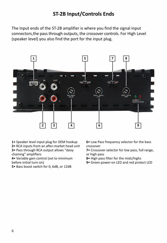
ST-2B Input/Controls Ends
The Input ends of the ST-2B amplifier is where you find the signal input connectors,the pass through outputs, the crossover controls. For High Level(speaker level) you also find the port for the input plug.
6
1• Speaker level input plug for OEM hookup2• RCA inputs from an after-market head unit3• Pass through RCA output allows "daisychaining" amplifiers4• Variable gain control (set to minimum before initial turn-on)5• Bass boost switch for 0, 6dB, or 12dB
6• Low Pass frequency selector for the basscrossover7• Crossover selector for low pass, full range,or high pass8• High pass filter for the mids/highs9• Green power-on LED and red protect LED
2 3
1 7
94
85
6

7
ST-4B Input/Controls Ends
The ST-4B has similar functions as the ST-2B but the 4 channel layout puts thecontrols in different positions.
3 4
2 5 9
7 8 12
1
6 10
11 13
1• Speaker level input plug for OEM hookup2• Front crossover function selector for fullrange of high pass3• Front High Pass frequency control4• Front Channels Variable gain control (set to minimum before initial turn-on)5• Front channels RCA inputs6• Pass through RCA output (rear channels can feed another amp)
7• Rear channels RCA inputs8• Rear Channels Variable gain control (set to minimum before initial turn-on)9• Rear channels Bass Boost switch for 0, 6dB, or 12dB10• Rear Low Pass frequency control11• Rear crossover function switch for high pass,full range, or low pass12• Rear High Pass frequency control13• Green power-on LED and red protect LED

8
ST-1B Input/Controls Ends
The ST-1B has similar functions as the other ST-B amps but the 1 channel layoutputs the controls in different positions. Plus the ST-1B has a remote control port.
1• RCA inputs2• RCA outputs3• Variable gain control (set to minimumbefore initial turn-on)4• Crossover function selector for full rangeof low pass
5• Low Pass frequency control6• Sub Sonic filter7• 0-180° Phase control8• 0-12 dB Bass boost control9• Remote control port10• Power/protect LED
3
2 4 7
6 10
1
5 8
9

9
Speaker Wiring of the ST-B Amplifiers
The Very Basics• No speaker wires can be shorted to, or touching either ground or each other.
This will put the amp into protect and may damage the amplifier• When bridging the left and right channels of any ST-B amplifier, you
use the left channel (Ch1) positive and the right channel (Ch2) negative, asindicated on the chassis by the speaker terminals
ST-2B Speaker Wiring
2Ch Stereo ModeA simple 2 speaker hookup for a right and left stereo pair. Speakers can be 2Ω or 4Ω.
Single Channel ModeThe ST-2B can be used in bridged mono mode to drive a single speaker or a woofer.NOTE that in bridged mono mode the speaker load must be 4Ω minimum.
4Ω / 8Ω

3Ch ModeIt is possible to run the 2Ch amps in “3-Channel” mode by running a pair ofspeakers for the mids and highs on left and right channels, and at the same timerun a woofer bridged between the L+ and R- terminals as shown. However, sinceeach channel will see 1/2 the impedance of the woofer you must use a woofer of noless than 4Ω. The amplifier sees impedance by frequency, so you can have two 2Ωloads but you must use a passive crossover on each speaker in the three channelmode. With the crossovers in the line, the amplifier will always see a minimum loadof 2Ω on each channel at all frequencies.
• Main speakers can be 2Ω~4Ω. Woofer can be 4Ω~8Ω but cannot be less than4Ω (as in any bridged situation)
• The active amp crossovers are not used in this system
A 3-Way hookup requires a coil on thewoofer and capacitors on the highs toact as a crossover and maintain correct impedance. Consult the speaker manufacturerfor correct cap and coil values.
2Ω Min
10
4Ω Min
All speakers 2Ω Min
11
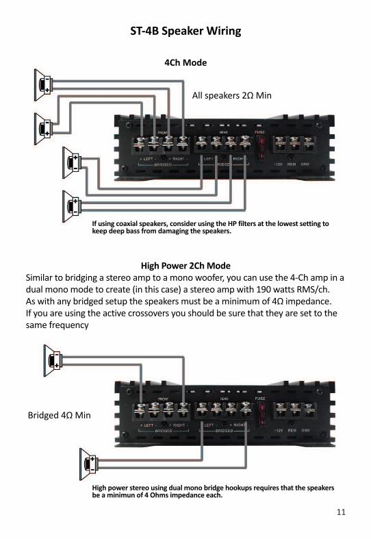
ST-4B Speaker Wiring
4Ch Mode
If using coaxial speakers, consider using the HP filters at the lowest setting tokeep deep bass from damaging the speakers.
High Power 2Ch ModeSimilar to bridging a stereo amp to a mono woofer, you can use the 4-Ch amp in adual mono mode to create (in this case) a stereo amp with 190 watts RMS/ch.As with any bridged setup the speakers must be a minimum of 4Ω impedance.If you are using the active crossovers you should be sure that they are set to thesame frequency
High power stereo using dual mono bridge hookups requires that the speakersbe a minimun of 4 Ohms impedance each.
Bridged 4Ω Min

2-way Active SystemUsing the built-in active crossovers of the ST-4B, you can easily create an active2-way system with mid/highs on the front channels and bass on the rear channels.Below is an active system with a bridged subwoofer on the rear channels.
5Ch SystemThe 5-speakers system requires a passive crossover between the front highs andthe mono woofer, with capacitors on the front highs positives and a coil on thewoofer positive. All amplifiers channels are full range.
Highs 2Ω Min
Mono Bass 4Ω Min
Highs 2Ω Min
Bass 4Ω Min
12
Highs 2Ω Min

13
ST-1B Speaker Wiring
The ST-1B has two + and two - terminals so you can hook up one woofer or two.One woofer can be 2Ω minimum. Two woofers must be 4Ω minimum each.
Technical Specifications
2Ω Min
ST-2BPower @ 4Ω: 2 x 65 wattsPower @ 2Ω: 2 x 90 wattsPower @ 4Ω Bridged: 180 wattsTHD @ Rated Power < 0.1%Signal to Noise Ratio > 97dBChannel separation > 45dBFreq. Response 20Hz-20KHz ±1dBInput Sensitivity .25v to 5vDim. in mm: 182(W) x 52(H) x 200(L)Overall: 182(W) x 52(H) x 230(L)
ST-4BPower @ 4Ω: 4 x 65 wattsPower @ 2Ω: 4 x 90 wattsPower @ 4Ω Bridged: 2 x 180 wattsTHD @ Rated Power < 0.2%Signal to Noise Ratio > 97dBChannel separation > 45dBFreq. Response 20Hz-20KHz ±1dBInput Sensitivity .25v to 5vDim. in mm: 182(W) x 52(H) x 280(L)Overall: 182(W) x 52(H) x 310(L)
ST-1BPower @ 4Ω: 200 wattsPower @ 2Ω: 300 wattsTHD @ Rated Power < 0.2%Signal to Noise Ratio > 97dBInput Sensitivity .25v to 5vDim. in mm: 182(W) x 52(H) x 280(L)Overall: 182(W) x 52(H) x 310(L)

1
Modesto, California USASince 1974
zapco.com