
SSL Fusion User Guide - sslweb.solidstatelogic.com.s3...
35
Fusion. This is SSL. FUSION User Guide www.solidstatelogic.com
Transcript of SSL Fusion User Guide - sslweb.solidstatelogic.com.s3...

Fusion. This is SSL.
FUSIONUser Guide
www.solidstatelogic.com

Visit SSL at:
www.solidstatelogic.com
© Solid State Logic
All rights reserved under International and Pan-American Copyright Conventions
SSL® and Solid State Logic® are ® registered trademarks of Solid State Logic.
Fusion™ is a trademark of Solid State Logic.
TBProAudio™ is a trade mark of TB-Software GbR.
All other product names and trademarks are the property of their respective owners and are hereby acknowledged.
No part of this publication may be reproduced in any form or by any means, whether mechanical or electronic,without the written
permission of Solid State Logic, Oxford, OX5 1RU, England.
As research and development is a continual process, Solid State Logic reserves the right to change the features and
specifications described herein without notice or obligation.
Solid State Logic cannot be held responsible for any loss or damage arising directly or indirectly from any error or omission in
this manual.
PLEASE READ ALL INSTRUCTIONS, PAY SPECIAL HEED TO SAFETY WARNINGS.
E&OE
September 2018

The Path To FusionA little over two years ago, we set out to create a new piece of analogue equipment that would enhance any engineer’s studio setup
and easily attach to a pair of inputs and outputs on an audio interface or an analogue desk/summing mixer. In true SSL fashion,
this piece of equipment would seek to enhance not only the sound of the mix but also the workflow of whatever situation it would
be thrust into - a new analogue ‘sidekick’, if you will.
The critical path in any mix leads to the master mix bus, where all the individual instruments are bound together. In today’s hybrid
studio, the prevalence and importance of mix bus processing is ever-present. The DAW’s mix bus inserts slots are often stacked
high with plug-ins seeking to inject various aspects of analogue mojo or magic. However, even after all insert slots are filled, that
authentic analogue edge is still lacking and can often prove difficult to achieve convincingly when mixing inside the box alone.
Engineers often look towards multiple pieces of real analogue outboard equipment instead and this was the seed from which Fusion
as an idea began to grow.
We started the journey through months of research - subjectively listening to and objectively measuring a vast array of analogue
equipment, to pinpoint all of the most desirable analogue characteristics and behaviours. This “hit list” of differing sonic flavours,
difficult to achieve with digital emulations alone, formed the base from which Fusion’s five analogue colour circuits would be
engineered.
“The Analogue Hit List” ➤ #1 - A rich analogue EQ with gentle shelving filters.
➤ #2 - Smooth top-end rounding, in the analogue domain.
➤ #3 - Additional harmonics and gradual saturation that emerge from an analogue ‘sweet spot’.
➤ #4 - Wider stereo imaging with more depth via true Mid/Side processing.
➤ #5 - Transformer mojo.
The first circuit to emerge as a result of the work was the VIOLET EQ, a new SSL shelving EQ with a refined ±9dB gain range. Next
came the HF COMPRESSOR circuit as a tool to tame unwanted top-end brittleness and restore a natural analogue roll-off. Then
came the VINTAGE DRIVE circuit, our new non-linear saturation circuit that was tweaked over several months to hone its unique
character. The STEREO IMAGE circuit followed as a way of providing the often much-missed analogue mid-side processing.. The
custom-designed TRANSFORMER circuit completed the final piece of the puzzle and again involved many rounds of fine-tuning
to settle on the design. But we didn’t just design Fusion in the isolation of SSL HQ; when the first prototypes were complete we sent
them off to a selection of trusted engineers and made further adjustments to the circuits based on their feedback.
Let The Fun Begin...And with that, you have a brief insight into how Fusion came to be. Fusion provides an armoury of mix tools at your disposal and
will help you arrive at the sound you want with ruthless efficiency!
Give your mix the analogue edge it deserves.
Happy Mixing.

Contents
Fusion Owner’s Manual
Table of ContentsIntroduction 1
Features 1
Unpacking 2
Safety Notices 2
Rack Mounting, Heat & Ventilation 2
Hardware Overview 3Front Panel 3
Rear Panel 3
Signal Flow Overview 4
Setup Examples 5Connecting Fusion to an Audio Interface 5
Using Fusion as a Hardware Insert 5Alternative Setup Option 5
Connecting Fusion to an Analogue Desk / Summing Mixer 6
Start Me Up! 7Tutorial 8
Input Trim 8HPF (High-Pass Filter) 8
The 5 Colour Circuits 9
Vintage Drive 9Violet EQ 11HF Compressor (High Frequency Compressor) 12Stereo Image 12Transformer 13Insert (Standard Mode) 14Insert (M/S Mode) 14Bypass (Standard Mode) 14Bypass (Post I/P Trim) 14Output Trim 14Master Meter 15FRONT PANEL SWITCHES 15
Settings Mode & Factory Reset 16Entering Settings Mode 16
Brightness 16Relay Feedback 16Exiting Settings Mode 16Factory Reset 17Simon Says Game 17
Troubleshooting & FAQ's 18UID Display Mode 18
Unique ID (UID) 18Hardware Revision 18
Soak Mode 19
Warranty 19

Contents
Fusion Owner’s Manual
All returns 19
Appendix A - Physical Specification 20Connectors 20
Appendix B - Analogue Specification 21Audio Performance 21
Appendix C - System Block Diagram 23Appendix D - Safety Notices 24
General Safety 24Installation Notes 24Power Safety 24CE Certification 25FCC Certification 25RoHS notice 25Instructions for disposal of WEEE by users in the European Union 25Electromagnetic Compatibility 26Environmental 26
Appendix E - Selecting Mains Voltage 27Changing the fuse from 115V to 230V 27
Changing the fuse from 230V to 115V 28
Appendix F - Recall Sheet 29

Fusion User Guide
Introduction
1
IntroductionFusion is an all-analogue stereo outboard processor created for the hybrid studio. Fusion introduces five completely new analogue
colouration tools designed to bring the perfect combination of added tonal character, clarity and depth to your mix bus or stereo
stems with the detail, warmth and finesse that only real analogue circuits can provide.
Features ➤ Five new SSL analogue colour circuits:
➤ VINTAGE DRIVE - A unique non-linear saturation circuit designed to bring that cherished gradual analogue
overload sound you get from pushing vintage equipment into the sweet spot.
➤ VIOLET EQ - a 2-band, minimum phase-shift shelving EQ offering instant low-end weight and glorious high-end
sheen. 4 fixed frequency points for each band with ±9dB boost/cut.
➤ HF COMPRESSOR - A high-frequency compressor, optimised for smooth taming of unwanted brittle sounds or
build-up of top-end fizz.
➤ STEREO IMAGE - A built-in M/S circuit allows for sumptuous sculpting of the side-signal to allow for wider mixes
with added depth.
➤ TRANSFORMER CIRCUIT - A custom SSL design that introduces subtle low-frequency harmonics for added
weight, alongside a touch of added transformer sparkle in the highs.
➤ Built-In Insert Point with two modes of operation:
➤ Stereo mode allows you to integrate additional outboard gear such as the SSL Bus Compressor. Switchable pre/
post the VIOLET EQ.
➤ Mid/Side mode allows you to insert two different mono outboard processors across the mid and side signals of the
mix. Switchable pre/post the STEREO IMAGE controls.
➤ 3rd order HPF (High-Pass Filter) to clean up unwanted low-end.
➤ SuperAnalogueTM ±12dB centre-indented INPUT and OUTPUT trim controls to help achieve the best possible gain-staging
into and out of Fusion.
➤ Individual bypass switches for each circuit to compare sounds with/without each circuit.
➤ Master BYPASS switch with two modes of operation:
➤ Red mode: complete bypass.
➤ White mode: bypass that includes the INPUT TRIM control.
➤ Master meter, with 3-second peak hold segments. Switches from output to input metering upon pressing the BYPASS switch.
➤ Input clip O/L LEDs, triggered at +27dBu.
➤ Balanced XLR input and outputs throughout for easy and professional studio integration.
➤ Enhanced ‘dot-dash’ screening around controls to allow for easier and clearer recall.
➤ Adjustable front-panel meter and switch brightness to match the vibe of your studio environment.

Introduction
2 Fusion User Guide
UnpackingThe unit has been carefully packed and inside the box you will find the following items.
➤ Fusion
➤ IEC power cord for your country
➤ Safety Sheet
➤ Quickstart Guide
➤ Registration card
It is always a good idea to save the original box and packaging, just in case you ever need to send the unit in for service.
Safety NoticesPlease read the safety notice information included on the Safety Sheet inside the box before using Fusion. This information is also
available in Appendix D of this User Guide.
ATTENTION: CHECK YOUR FUSE SETTINGS Fusion can be switched between operating with a 230V or 115V power source. Please see Appendix E: Selecting Mains Voltage for details on how to check your fuse settings and change if necessary.
Rack Mounting, Heat & VentilationFusion is a 2U, 19” rackmount piece of equipment designed to sit in the racking of a producer’s desk or similar. Fusion’s no
compromise design is powered by a toroidal transformer and as such, the left-hand side of the unit can become warm to the
touch. It is recommended that ventilation space is left above and below the unit. If this is not possible, then it is recommended
Fusion be placed at the top of the rack, so any heat generated by Fusion rises away from surrounding equipment. The sides of
the Fusion chassis have cut-outs that should under no circumstances be blocked or covered. Always allow Fusion to cool down
before handling.
Fusion User Guide
Hardware Overview
3
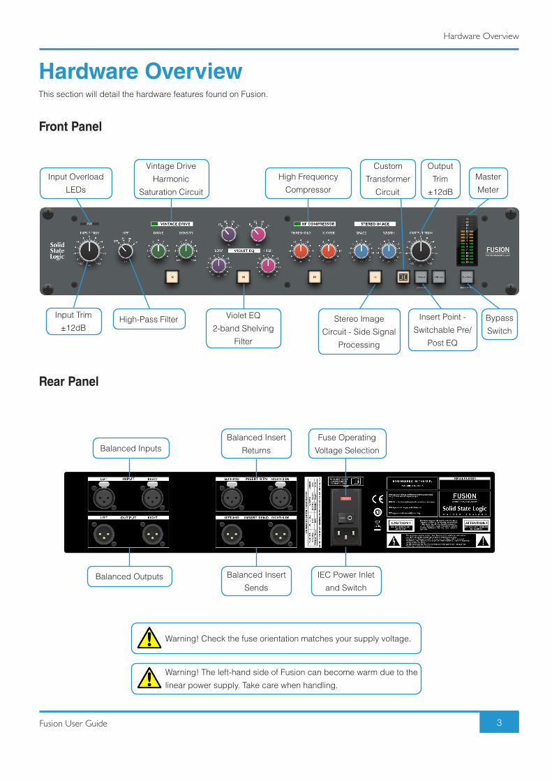
Hardware OverviewThis section will detail the hardware features found on Fusion.
Front Panel
Rear Panel
Input Overload
LEDs
High-Pass Filter
Vintage Drive
Harmonic
Saturation Circuit
High Frequency
Compressor
Stereo Image
Circuit - Side Signal
Processing
Custom
Transformer
Circuit
Insert Point -
Switchable Pre/
Post EQ
Violet EQ
2-band Shelving
Filter
Input Trim
±12dB
Output
Trim
±12dB
Master
Meter
Bypass
Switch
Balanced Insert
Sends
IEC Power Inlet
and Switch
Balanced Insert
Returns
Fuse Operating
Voltage SelectionBalanced Inputs
Balanced Outputs
Warning! Check the fuse orientation matches your supply voltage.
Warning! The left-hand side of Fusion can become warm due to the
linear power supply. Take care when handling.

Fusion User Guide
Hardware Overview
4
Signal Flow OverviewA detailed Block Diagram is available in Appendix C. The diagram below gives you an overview of the signal path options Fusion
provides.
INSERT (Standard)
INSERT (Standard) + Pre EQ
INSERT (M/S Mode)
INSERT (M/S Mode) + Pre EQ
HPF INSERTPOINT
VINTAGEDRIVE
STEREOIMAGE
VIOLETEQ TRANSFORMER
HF COMPRESSOR
HPFM/S
INSERTPOINT
VINTAGEDRIVE
STEREOIMAGE
VIOLETEQ TRANSFORMER
HF COMPRESSOR
HPFM/S
INSERTPOINT
VINTAGEDRIVE
STEREOIMAGE
VIOLETEQ TRANSFORMER
HF COMPRESSOR
HPFINSERTPOINT
VINTAGEDRIVE
STEREOIMAGE
VIOLETEQ
TRANSFORMERHF COMPRESSOR

5Fusion User Guide
Setup Examples
Setup ExamplesConnecting Fusion to an Audio InterfaceThe examples below show how to connect Fusion to an audio interface, with and without hardware insert functionality in your DAW.
Using Fusion as a Hardware Insert1. Choose a pair of analogue inputs and outputs that are not being used on your audio interface - this example uses analogue
inputs and outputs 3 & 4, presuming 1 & 2 are being used for monitoring.
2. Connect analogue outputs 3 & 4 of your audio interface to the left and right inputs of Fusion.
3. Connect the left and right outputs of Fusion into line-level inputs 3 & 4 of your audio interface.
4. Insert Fusion across your DAW mix bus track / any stereo audio track as a hardware insert in your DAW.
Alternative Setup OptionIf you do not use the hardware insert functionality in your DAW, you can use the following method to integrate Fusion into your setup:
1. Choose a pair of analogue inputs and outputs that are not being used on your audio interface e.g. outputs 3 & 4 and inputs
1 & 2.
2. On your main DAW mix bus / stereo output track, make the output analogue 3 & 4. This example presumes analogue outputs
1 & 2 are connected to your monitors.
3. Connect analogue outputs 3 & 4 to the left and right inputs of Fusion.
4. Connect the left and right outputs of Fusion into line-level analogue inputs 1 & 2 of your audio interface.
5. Create a Stereo Input track that is sourced from analogue inputs 1 & 2 in your DAW. Record enable/input monitor this track.
Set the output of this track to outputs 1 & 2 of your interface (your monitor output).
6. Print the Fusion mix back in by recording the track.

6 Fusion User Guide
Setup Examples
Connecting Fusion to an Analogue Desk / Summing MixerFusion is the ideal analogue processor to complement your analogue summing system. The example below shows how to connect
Fusion and an SSL Bus Compressor to your analogue desk or summing mixer.
1. Connect the mix bus insert send outputs of your analogue desk / summing mixer to Fusion’s inputs.
2. Connect the outputs of Fusion to the mix bus insert returns of your analogue desk / summing mixer.
3. Connect the insert send outputs on Fusion to the G Series Compressor inputs.
4. Connect the outputs of the G Series Compressor to Fusion's insert returns.

7Fusion User Guide
Start Me Up!
Start Me Up!The tutorial section that follows explores each colour circuit in detail but if you cannot wait to get started, the front panel settings
below provide a good starting point for immediately improving your mix with Fusion.
Remember, a number of Fusion’s circuits are level-dependent and this will affect the sound you get. Depending on how loud or quiet your mix already is, you may need to start by adjusting the INPUT TRIM in order to achieve the best possible gain-staging. As a guide, adjust the INPUT TRIM, or DRIVE control until the VINTAGE DRIVE tri-colour LED consistently lights green, with occasional flickers of orange. Similarly, adjust the THRESHOLD control (in the
HF COMPRESSOR section) so that it only occasionally flickers green in response to sibilance and harshness. Use the OUTPUT TRIM to compensate for any significant level increases and retain a sensible output level that does not clip your audio interface converter inputs.
"Mix Bus Mojo"
"Expensive Vocals"
"Aggressive Bass"

Fusion User Guide
Tutorial
8
TutorialThis section will go into detail about each front panel section.
O/LLeft and Right Overload LEDs light red if the signal at Fusion’s input exceeds +27dBu.
Input TrimThe INPUT TRIM provides ±12dB gain at the input stage of Fusion. This pot is indented at the 12 o’clock
position. You should use this control to achieve the best gain-staging through Fusion. Try starting with the
pot at the indented 0 dB position if you are at the beginning of a the mixing process. If you are strapping
Fusion across a ‘hot’ mix that is already approaching the kind of levels you would deliver to a mastering
engineer, try pulling back the INPUT TRIM by 2-4dB first. If you are using Fusion to add character to an
individual stem, try increasing the INPUT TRIM, which will in turn drive the following VINTAGE DRIVE
section even harder if engaged.
HPF (High-Pass Filter)The High-Pass Filter allows you to reduce sub frequency content in your mix. The filter is a 3rd order/18dB
per octave slope. The pot is stepped and allows you to choose between four fixed settings - OFF, 30Hz, 40Hz
and 50Hz. OFF or 30Hz are often suited to whole mix material, whilst the 40Hz and 50Hz can help remove
unnecessary rumble when processing individual instrument stems. Removing this low-energy from stems can
give you back some headroom in the overall mix.
HPF Plots - OFF, 30Hz, 40Hz, 50Hz.

Fusion User Guide
Tutorial
9
The 5 Colour CircuitsThe descriptions that follow cover each of Fusion’s 5 colouration circuits. Each circuit has an associated IN switch which allows you
to switch that particular circuit in or out. When a circuit is on it turns orange. When bypassed, the switch is backlit a soft white colour.
Vintage DriveVINTAGE DRIVE is a unique, non-linear saturation circuit that gives your mix added
strength and cohesion. This circuit has been designed to bring the kind of cherished
‘gradual analogue overload’ sound that the best kind of vintage analogue outboard and
consoles offer when you drive level into the sweet spot.
Use the DRIVE pot to work the VINTAGE DRIVE section harder. You increase the drive
by moving the pot from left to right - front-panel marking 1 is least amount of drive, 11 is
the most. This control automatically compensates for the level increase at the output of
the VINTAGE DRIVE circuit. A tri-colour LED accompanies this section and provides
feedback as to how hard the circuit is being driven. If you are looking for a subtle effect
that works across a whole mix, keep the LED in the green zone (occasional flickers into
orange are fine). If you want a more aggressive colour, then drive the circuit until the LED
starts showing orange more consistently. When in the red zone you will notice quite obvious
distortion which isn't desirable across a mix bus but can work well on individual stems.
The DENSITY pot is used to fine tune the type of effect the circuit produces. Lower settings (generally below 3) produce additional
harmonics with an emphasis towards even-order harmonics. DENSITY settings between 2 and 3 can help add richness to a
mix. Medium to higher DENSITY settings from 3 onwards, result in a gradual lowering of the overall harmonic content but with
the odd-order harmonics eventually becoming more prominent than the even-order harmonics. The third harmonic is related to
the saturation/analogue clipping effect that this circuit imparts. This can be thought of as a kind of ‘soft-compression’ - peaks are
rounded and the RMS (average) level is brought up. This helps you gain some additional ‘loudness’. Settings between 3 and 7
work well for thickening whole mixes.
TIP 1: The DENSITY control does raise the overall level of the signal, as you move it from MIN to MAX. Be sure to use the OUTPUT TRIM control to compensate.
TIP 2: A good starting point for the controls of this circuit is DRIVE at 5 and DENSITY at 5. However, the DRIVE setting will be very much dependent on how loud/quiet your mix is already.
TIP 3: The lowest DENSITY setting marked MIN offers a dynamic ‘expansion’ effect when driven hard with the preceding DRIVE control. It works well to accentuate individual stem sounds that are already dense - e.g. bringing the pluck out of a distorted bass guitar. For full mixes, it is recommended to go no lower than 2 with the DENSITY setting.

Fusion User Guide
Tutorial
10
Example of additional harmonics generated using a 1kHz tone. ('Low' Density)
Example of additional harmonics generated using a 1kHz tone. ('High' Density)
VINTAGE DRIVE bypassed. VINTAGE DRIVE engaged.
Example of the saturated compression effect introduced by medium to higher Density settings. Right-hand readout shows Fusion increase the RMS level, with same Maximum Peak.
Fusion User Guide
Tutorial
11
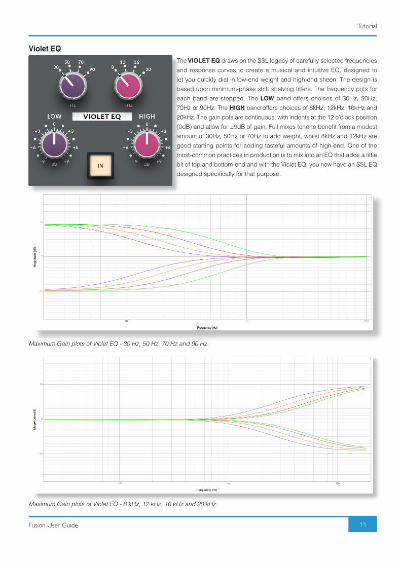
Violet EQThe VIOLET EQ draws on the SSL legacy of carefully selected frequencies
and response curves to create a musical and intuitive EQ, designed to
let you quickly dial in low-end weight and high-end sheen. The design is
based upon minimum-phase shift shelving filters. The frequency pots for
each band are stepped. The LOW band offers choices of 30Hz, 50Hz,
70Hz or 90Hz. The HIGH band offers choices of 8kHz, 12kHz, 16kHz and
20kHz. The gain pots are continuous, with indents at the 12 o’clock position
(0dB) and allow for ±9dB of gain. Full mixes tend to benefit from a modest
amount of 30Hz, 50Hz or 70Hz to add weight, whilst 8kHz and 12kHz are
good starting points for adding tasteful amounts of high-end. One of the
most-common practices in production is to mix into an EQ that adds a little
bit of top and bottom-end and with the Violet EQ, you now have an SSL EQ
designed specifically for that purpose.
Maximum Gain plots of Violet EQ - 30 Hz, 50 Hz, 70 Hz and 90 Hz.
Maximum Gain plots of Violet EQ - 8 kHz, 12 kHz, 16 kHz and 20 kHz.

Fusion User Guide
Tutorial
12
HF Compressor (High Frequency Compressor)This is a compressor circuit that only compresses high-frequencies. It helps to introduce a
‘tape-like’ top-end roll-off by taming unwanted brittleness or harshness that can sometimes
build up in a mix or individual stem sound. The cause might be due to over-use of plug-ins
with top-end ‘hype’. The front panel THRESHOLD determines at what point compression
starts to occur, whilst X-OVER determines the frequencies that are affected by the
compression. Other typical compressor parameters such as attack, release and ratio are
all fixed in the design, having been optimised for the best transparency.
A good starting point for full mix material is THRESHOLD at +2dB and X-OVER around
15kHz. The best approach is to move the controls until the accompanying HF Compressor
tri-colour LED just starts to flicker green occasionally. A sustained green, into orange will
likely be too heavy-handed for most mixes. It must be noted that there is no automatic
makeup gain, as commonly found on digital single-band compressors. This means you
will not be fooled by a flattering gain make-up. Another important thing to note is that if the
mix is already well balanced and mixed, you may not need to engage this circuit at all! However, when used subtly, it can smooth
harshness off in a very pleasing way. On individual stems, like bass guitars, you can be more aggressive with it.
TIP: A nice trick is to deliberately apply more high-end than you would normally in the preceding VIOLET EQ section (apply more gain on your chosen HIGH frequency) and then use the HF COMPRESSOR to tame it back. This can often help achieve a brighter top end, without the harshness.
Stereo ImageThe STEREO IMAGE circuit allows for true mid-side processing within Fusion. Mid-Side
is a technique commonly used in mastering that separates a stereo signal into 2 channels
- one for the sounds in the centre (mid) of a stereo image and the other for the sounds on
the edges of the stereo image (side). The WIDTH allows you to increase the level of the
side signal only, to generally widen or narrow the stereo image. The SPACE control allows
you to experiment with a broad boost or cut of bass frequencies in the side signal and this
feature is based upon the often overlooked but quite brilliant ‘Stereo Shuffling’ processing
technique. Many people think of wanting to remove bass from the side signals but this
SPACE control may have you re-thinking that approach as you can inject some really
interesting depth effects into the mix. SPACE settings beyond +4dB on whole mixes may
be too extreme, so try between +2dB and +4dB to start with.
Fusion User Guide
Tutorial
13
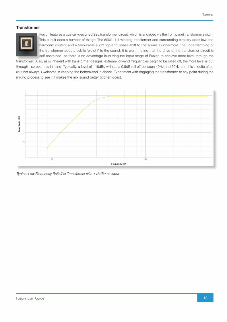
TransformerFusion features a custom-designed SSL transformer circuit, which is engaged via the front panel transformer switch.
This circuit does a number of things: The 600Ω, 1:1 winding transformer and surrounding circuitry adds low-end
harmonic content and a favourable slight top-end phase-shift to the sound. Furthermore, the underdamping of
the transformer adds a subtle ‘weight’ to the sound. It is worth noting that the drive of the transformer circuit is
self-contained, so there is no advantage in driving the Input stage of Fusion to achieve more level through the
transformer. Also, as is inherent with transformer designs, extreme low-end frequencies begin to be rolled off, the more level is put
through - so bear this in mind. Typically, a level of +16dBu will see a 0.5dB roll off between 40Hz and 30Hz and this is quite often
(but not always!) welcome in keeping the bottom-end in check. Experiment with engaging the transformer at any point during the
mixing process to see if it makes the mix sound better (it often does).
Typical Low Frequency Rolloff of Transformer with +16dBu on input.

Fusion User Guide
Tutorial
14
Insert (Standard Mode)Fusion features a stereo insert point, which provides the ability to introduce other outboard processors
such as the SSL G-Series Bus Compressor. The insert point is engaged via the front panel INSERT switch
and will light bright white when operating in standard stereo mode. The PRE EQ switch allows for the
insert pont to be moved before the VIOLET EQ section in the signal path.
Insert (M/S Mode)Pressing and holding the INSERT switch for two seconds will cause it to enter Mid-Side mode, indicated
by the front panel switch(es) turning blue. The Insert Send and Return Left connectors become the ‘Mid’
channel insert and the Insert Send and Return Right connectors become the ‘Side’ channel insert. This
provides the option of using one piece of mono outboard equipment to process the mid signal only and
another to process the side signal (a common mastering technique). Pressing the PRE EQ switch in this
mode moves the insert to be before the Stereo Image circuit. By default, it is post the Stereo Image circuit.
Bypass (Standard Mode)The BYPASS switch allows you to bypass all of Fusion’s processing blocks. If the BYPASS switch is red, then you
are in standard BYPASS mode. Use this to compare the sound of the mix with/without Fusion in one easy action. It
dimly lights white if you are not in bypass.
Bypass (Post I/P Trim)Pressing and holding the BYPASS switch for two seconds will cause it to enter POST INPUT TRIM bypass mode.
You will know because the front panel switch will turn bright white. In this mode, the INPUT TRIM pot still affects
the sound, even in bypass. This mode is a useful extra feature if you’ve had to make-up or take off significance
amounts of gain using the INPUT TRIM.
Output TrimThe OUTPUT TRIM provides ±12dB gain at the output stage of Fusion. This pot is indented at the 12
o’clock position. This control is important in order to compensate for any level increases caused by the
preceding sections.

Fusion User Guide
Tutorial
15
Master MeterA master meter, with three second peak hold allows you view the main output level of Fusion. The scale is
referenced in dBu, with +24dBu at the top. The aim of the game is not to max out this meter - typically full mix
material would be peaking between +9dBu and +15dBu, occasionally as high as +18dBu. Ensure that the output
level of Fusion does not exceed the operating input level of your A/D converter, otherwise it will clip.
TIP: When BYPASS is engaged, the master meter automatically becomes an input level meter, so you can see your incoming level in more detail.
FRONT PANEL SWITCHESThe switches used in Fusion are solid state switches that trigger a single relay for audible feedback. The benefit of this approach is
that it allows for the front panel switches to be repurposed for additional functions, such as settings and secondary switch modes
(M/S mode on the Insert Switch for example). The relay provides acoustic feedback for a traditional 'analogue' feel. The relay
feedback can be switched off in the Settings Mode, specified on page 16.
Fusion User Guide
Settings Mode & Factory Reset
16
Settings Mode & Factory ResetThis section will detail how to enter Fusion's Settings Mode and the functionality that can be changed. It also details how to reset
Fusion back to a factory default state.
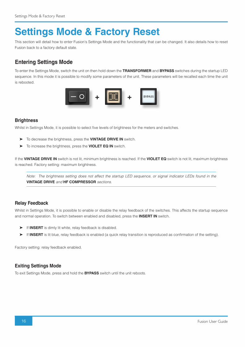
Entering Settings ModeTo enter the Settings Mode, switch the unit on then hold down the TRANSFORMER and BYPASS switches during the startup LED
sequence. In this mode it is possible to modify some parameters of the unit. These parameters will be recalled each time the unit
is rebooted.
BrightnessWhilst in Settings Mode, it is possible to select five levels of brightness for the meters and switches.
➤ To decrease the brightness, press the VINTAGE DRIVE IN switch.
➤ To increase the brightness, press the VIOLET EQ IN switch.
If the VINTAGE DRIVE IN switch is not lit, minimum brightness is reached. If the VIOLET EQ switch is not lit, maximum brightness
is reached. Factory setting: maximum brightness.
Note: The brightness setting does not affect the startup LED sequence, or signal indicator LEDs found in the VINTAGE DRIVE and HF COMPRESSOR sections.
Relay FeedbackWhilst in Settings Mode, it is possible to enable or disable the relay feedback of the switches. This affects the startup sequence
and normal operation. To switch between enabled and disabled, press the INSERT IN switch.
➤ If INSERT is dimly lit white, relay feedback is disabled.
➤ If INSERT is lit blue, relay feedback is enabled (a quick relay transition is reproduced as confirmation of the setting).
Factory setting: relay feedback enabled.
Exiting Settings ModeTo exit Settings Mode, press and hold the BYPASS switch until the unit reboots.
+ +

Fusion User Guide
Settings Mode & Factory Reset
17
Factory ResetTo reset Fusion to factory settings, switch the unit on then hold down the VINTAGE DRIVE IN and BYPASS switches during the
startup LED sequence.
Factory Reset allows reset of any stored settings (Brightness, Relay feedback, BYPASS and INSERT configurations) to the factory
default. Press and hold the combination of switches until all the switches start flashing. After releasing the switches, the unit will
automatically reboot and the factory settings will be restored.
Simon Says GameTo play the Simon Says game, switch the unit on and hold down all four IN switches during the startup LED sequence.
The BYPASS switch will flash red. The highest score achieved on the unit is shown on the master meters; the right bar meter is
points x1, the left bar meter is points x10 (e.g. two LEDs lit on the left and six LEDs lit on the right means that the current highest
score is 26). If the maximum score is reached, the two top red LEDs are lit. Factory reset does not affect the highest score for the
unit.
1. Press the flashing BYPASS switch to start a round.
2. A random switch between the first four switches will light up briefly (The relay will also click a number of times equal to the
position of the switch; switch 1 = 1 click, switch 2 lit = 2 clicks etc).
3. The aim of the game is to press the correct switch within four seconds. If the wrong switch is pressed or a timeout of four
seconds elapses, the game resets.
4. If you press the correct switch, you move to the next level and another switch is added to the sequence.
Note: Every three levels the difficulty increases by displaying the sequence faster.
To exit this mode, simply power -cycle the unit.
+ +VINTAGE DRIVE
+ + + +VINTAGE DRIVE
1 2 3 4
VIOLET EQ HF COMPRESSOR STEREO WIDTH
18 Fusion User Guide
Troubleshooting & FAQ's
Troubleshooting & FAQ'sFrequently Asked Questions can be found on the Solid State Logic Website at: http://www.solidstatelogic.com/support/fusion
If you require technical support for Fusion or other SSL Products, click on the Ask a
Question link on the support page to open a support ticket and an SSL Product Support
Engineer will be in contact.
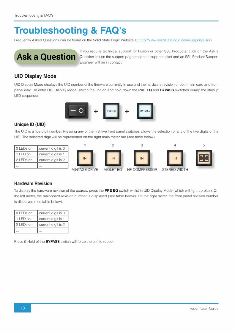
UID Display ModeUID Display Mode displays the UID number of the firmware currently in use and the hardware revision of both main card and front
panel card. To enter UID Display Mode, switch the unit on and hold down the PRE EQ and BYPASS switches during the startup
LED sequence.
Unique ID (UID)The UID is a five digit number. Pressing any of the first five front panel switches allows the selection of any of the five digits of the
UID. The selected digit will be represented on the right main meter bar (see table below).
0 LEDs on current digit is 0
1 LED on current digit is 1
2 LEDs on current digit is 2
... ...
Hardware RevisionTo display the hardware revision of the boards, press the PRE EQ switch whilst in UID Display Mode (which will light up blue). On
the left meter, the mainboard revision number is displayed (see table below). On the right meter, the front panel revision number
is displayed (see table below).
0 LEDs on current digit is 0
1 LED on current digit is 1
2 LEDs on current digit is 2
... ...
Press & Hold of the BYPASS switch will force the unit to reboot.
+ +
VINTAGE DRIVE
1 2
VIOLET EQ
3
HF COMPRESSOR
4
STEREO WIDTH
5

19Fusion User Guide
Troubleshooting & FAQ's
Soak ModeIn soak mode the unit will cycle through all possible colours and modes of LEDs, to allow verification of the unit. To enter Soak
Mode, switch the unit on and hold down the INSERT and BYPASS switches during the startup LED sequence.
The HPF rotary encoder allows you to stop the cycle on an arbitrary step if set to the “OFF” position. Setting the HPF rotary encoder
to any other position will cause the cycle to run again. The higher the position, the faster the pattern will cycle through.
Press & Hold of the BYPASS switch will force the unit to reboot.
WarrantyWarranty claims will only be accepted if the purchased product has been used for its intended purpose. Any purchased product
used for an unintended purpose will not be eligible for warranty protection. For all warranty inquiries or claims please address
your claim to the dealer that you purchased the product from – or to Solid State Logic if the purchase was directly from Solid State
Logic – within a period of two months from the date on which you detected its lack of conformity with the terms of the warranty.
Please include your original proof of purchase when initiating the claim.
➤ Within the EU: Pursuant to the Solid State Logic Terms and Conditions under European consumer law the purchaser has full
statutory warranty rights for two years from the date of purchase of the product. The warranty is valid only in those Member
States of the European Union (EU) who have adopted the applicable EU law into their national legislation. The applicable
national legislation governing the sale of consumer goods is not affected by this warranty.
➤ Outside of the EU: Outside of the European Union a 12 month warranty from date of purchase is applicable.
All returns ➤ No unit will be accepted for repair by Solid State Logic unless accompanied by a valid RMA (Return Material Authorisation)
number, obtainable from Solid State Logic prior to shipping.
➤ All units should be shipped to Solid State Logic in suitable rigid packaging – Solid State Logic cannot be held responsible
for any damage caused by shipping units in other packaging.
+ +

Fusion User Guide
Appendix A
20
Appendix A - Physical SpecificationDepth 303mm / 11.9 inches (chassis only)
328mm / 12.9 inches (total including front panel controls)
Height 88.9mm / 3.5inches (2 RU)
Width 480mm / 19 inches
Power 50 Watts maximum, 40 Watts typical
Unboxed Weight 5.86kg / 12.9lbs
Boxed Size 550mm x 470mm x 225mm (21.7" x 18.5" x 8.9")
Boxed Weight 9.6kg / 21.2lbs
Note: All physical specification values are approximate.
Connectors

Fusion User Guide
Appendix B
21
Appendix B - Analogue SpecificationAudio PerformanceDefault test conditions (unless otherwise stated):
- Source impedance of Test Set: 50Ω
- Input impedance of Test Set: 100kΩ
- Reference frequency: 1kHz
- Reference level: 0dBu
- All unweighted measurements are specified as 22Hz to 22kHz band limited RMS and are expressed in units of dBu.
- The onset of clipping (for headroom measurements) should be taken as 1% THD.
- Measurements taken with Input and Output trim at center position.
- All levels are intended balanced.
Unless otherwise quoted all figures have a tolerance of ±0.5dB or 5%.
Measurement Conditions Value
Input Impedance 10kΩ
Output Impedance 75Ω
Max Input Level 1% THD 27.5 dBu
Max Output Level 1% THD 27.5 dBu
Frequency Response All circuits off
- 20Hz to 20kHz
- -3dB low rolloff
- -3dB high rolloff
- ±0.05dB
- < 5Hz
- > 180kHz
THD+Noise All circuits off
- +20dBu, 1kHz (filter 22Hz to 22kHz)
Bypass
- +20dBu, 1kHz (filter 22Hz to 22kHz)
Vintage Drive
- Indicator Off
- Indicator Green
- Indicator Orange
- Indicator Red
- < 0.005%, 0.0025% typical
- 0.0005% typical
- < 0.2% typical
- 0.2% to 0.5% typical
- 0.5% to 2% typical
- > 2% typical
CMRR - 20Hz
- 1kHz
- > 78dB, 85dB typical
- > 78dB, 88dB typical
Noise Analyser filters/BW: 22Hz to 20kHz (AES17).
- All circuits off
- Bypass
- Vintage Drive, mid Drive, mid Density
- < -86dBu, -91dBu typical
- -94dBu typical
- -75dBu typical
Fusion User Guide
Appendix B
22
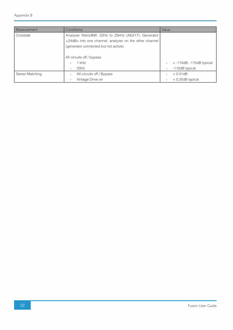
Measurement Conditions Value
Crosstalk Analyser filters/BW: 22Hz to 20kHz (AES17). Generator
+24dBu into one channel, analyzer on the other channel
(generator connected but not active).
All circuits off / bypass
- 1 kHz
- 20Hz
- < -110dB, -115dB typical
- -110dB typical
Stereo Matching - All circuits off / Bypass
- Vintage Drive on
- < 0.01dB
- < 0.25dB typical

23Fusion User Guide
Appendix C
Appendix C - System Block Diagram

24 Fusion User Guide
Appendix D
Appendix D - Safety NoticesGeneral Safety
- Read these instructions.
- Keep these instructions.
- Heed all warnings.
- Follow all instructions.
- Do not use this apparatus near water.
- Clean only with dry cloth.
- Do not block any ventilation openings. Install in accordance with the manufacturer’s instructions.
- Do not install near any heat sources such as radiators, heat registers, stoves or other apparatus (including amplifiers) that
produce heat.
- Do not defeat the safety purpose of the polarized or grounding-type plug. A polarized plug has two blades with one wider
than the other. A grounding type plug has two blades and a third grounding prong. The wide blade or the third prong are
provided for your safety. If the provided plug does not fit into your outlet, consult an electrician for replacement of the
obsolete outlet.
- Protect the power cord from being walked on or pinched particularly at plugs, convenience receptacles, and the point
where they exit from the apparatus.
- Only use attachments/accessories recommended by the manufacturer.
- Unplug this apparatus during lightning storms or when unused for long periods of time.
- Refer all servicing to qualified service personnel. Servicing is required when the apparatus has been damaged in any
way, such as power-supply cord or plug is damaged, liquid has been spilled or objects have fallen into the apparatus, the
apparatus has been exposed to rain or moisture, does not operate normally, or has been dropped.
- Do NOT modify this unit, alterations may affect performance, safety and/or international compliance standards.
- SSL does not accept liability for damage caused by maintenance, repair or modification by unauthorised personnel.
Installation Notes - When installing this apparatus either fix it into a standard 19” rack or place it on a secure level surface.
- If the unit is rack mounted, fit all rack screws. Rack shelves are recommended.
- When rack mounting allow a 1U gap above and below the unit for cooling.
- Ensure that no strain is placed on any cables connected to this apparatus. Ensure that all such cables are not placed where
they can be stepped on, pulled or tripped over.
WARNING: To reduce the risk of fire or electric shock do not expose this apparatus to rain or moisture.
ATTENTION: Afin de réduire les risques de choc électrique, ne pas exposer cet appareil à l'humidité ou à la pluie.
Power Safety - The unit is not supplied with a mains lead allowing you to use IEC distribution of mains cables of your choice. Any mains
cable used must fulfill the following:
- Refer to the rating label on rear of the unit and always use suitable mains cords.
- The unit should ALWAYS be earthed with the earth on both the IEC sockets (when both are used).
- Please use-compliant 60320 C13 TYPE SOCKET. When connecting to supply outlets ensure that appropriate sized
conductors and plugs are used to suit local electrical requirements.
- Maximum cord length should be 4.5m(15’).
- The cord should bear the approval mark of the country in which it is to be used.
- Connect only to an AC power source that contains a protective earthing (PE) conductor.
- Only connect units to single phase supplies with the neutral conductor at earth potential.

25Fusion User Guide
Appendix D
GB The apparatus shall be connected to mains socket outlets with a protective earthing connection.
DEN Apparatets stikprop skal tilsluttes en stikkontakt med jord, som giver forbindelse tilstikproppens jord.
FIN Laite on liitettävä suojamaadoituskoskettimilla varustettuun pistorasiaan.
NOR Apparatet må tilkoples jordet stikkontakt.
SWE Apparaten skall anslutas till jordat uttag.
ATTENTION! This unit has a selectable fuse for 115 Vac and 230 Vac operation, situated next to the mains inlet. When
changing the fuse always disconnect the unit from the mains outlet and only replace with the correct value of fuse. Refer
to the User Guide for further details.
WARNING! Un-earthed metal parts may be present inside the enclosure. No user-serviceable parts inside - to be
serviced only by qualified personnel. When servicing disconnect all power sources before removing any panels.
CE CertificationFusion is CE compliant. Note that any cables supplied with SSL equipment may be fitted with ferrite rings at each end.
This is to comply with the current regulations and these ferrites should not be removed.
FCC Certification - Do not modify this unit! This product, when installed as indicated in the instructions contained in the installation manual,
meets FCC requirements.
- Important: This product satisfies FCC regulations when high quality shielded cables are used to connect with other equipment.
Failure to use high quality shielded cables or to follow the installation instructions may cause magnetic interference with
appliances such as radios and televisions and will void your FCC authorisation to use this product in the USA.
- This equipment has been tested and found to comply with the limits for a Class A digital device, pursuant to part 15 of the
FCC Rules. These limits are designed to provide reasonable protection against harmful interference when the equipment is
operated in a commercial environment. This equipment generates, uses and can radiate radio frequency energy and, if not
installed and used in accordance with the instructions manual, may cause harmful interference to radio communications.
Operation of this equipment in a residential is likely to cause harmful interference in which case the user will be required to
correct the interference at his own expense.
RoHS noticeSolid State Logic complies with and this product conforms to European Union’s Directive 2011/65/EU on Restrictions of Hazardous
Substances (RoHS) as well as the following sections of California law which refer to RoHS, namely sections 25214.10, 25214.10.2,
and 58012, Health and Safety Code; Section 42475.2, Public Resources Code.
Instructions for disposal of WEEE by users in the European UnionThe symbol shown here, which is on the product or on its packaging, indicates that this product must not be disposed
of with other waste. Instead, it is the user’s responsibility to dispose of their waste equipment by handing it over to a
designated collection point for recycling of waste electrical and electronic equipment. The separate collection and
recycling of your waste equipment at the time of disposal will help to conserve natural resources and ensure that it
is recycled in a manner that protects human health and the environment. For more information about where you
can drop off your waste equipment for recycling, please contact your local city office, your household waste disposal service
or where you purchased the product.
WARNING: Cancer and Reproductive Harm - www.P65Warnings.ca.gov

26 Fusion User Guide
Appendix D
Evaluation of apparatus based on altitude not exceeding 2000m. There may be some potential safety hazard if the
apparatus is operated at altitude exceeding 2000m.
Evaluation of apparatus based on temperate climate conditions only. There may be some potential safety hazard if the
apparatus is operated in tropical climate conditions.
Electromagnetic CompatibilityEN 55032:2015, Environment: Class A, EN 55103-2:2009, Environments: E2 - E4.
Audio input and output ports are screened cable ports and any connections to them should be made using braid-screened cable
and metal connector shells in order to provide a low impedance connection between the cable screen and the equipment.
WARNING: Operation of this equipment in a residential environment could cause radio interference.
EnvironmentalTemperature: Operating: +1 to 30 degrees Celsius. Storage: -20 to 50 degrees Celsius.

27Fusion User Guide
Appendix E
Appendix E - Selecting Mains VoltageFusion has a linear power supply and therefore needs to be manually switched to operate with
either a 230V or 115V power suppy. The AC mains fuse is located on the rear panel next to the AC
mains connector. The orientation of the main fuse cartridge will dictate the operational voltage; this
can be either 230V or 115V AC power.
The operational value of the fuse is displayed through a slot on the fastening that holds the fuse in
place (as shown).
Note: Only one fuse is supplied with Fusion. Each operational voltage requires a different fuse: 230V - Current Rating 500mA, Voltage Rating 250 V AC, Body Material Glass(LBC), Size 5mmx20mm
115V - Current Rating 1A, Voltage Rating 250 V AC, Body Material Glass(LBC), Size 5mmx20mm
Changing the fuse from 115V to 230V1. Remove the IEC power cable from the IEC socket.
2. Remove the fastening by leveraging a flat-head screwdriver in the slot at the top of the fuse panel.
3. Remove the fuse cartridge, then remove the small metal link plate. Place the link plate on the opposite side of the fuse
cartridge (you will need to remove the fuse to do this).
4. Place the new fuse in the vacant slot on the opposite side of the fuse cartridge.
5. Re-orientate the fuse cartridge 180 degrees and reposition it so that the alternate operating voltage value is displayed
through the slot in the fastening. Re-seal the fastening, reconnect the IEC power cable, and switch the unit on.
115V

28 Fusion User Guide
Appendix E
Changing the fuse from 230V to 115V
1. Remove the IEC power cable from the IEC socket.
2. Remove the fastening by leveraging a flat-head screwdriver in the slot at the top of the fuse panel.
3. Remove the fuse cartridge, then remove the small metal link plate. Place the link plate on the opposite side of the fuse
cartridge (you will need to remove the fuse to do this).
4. Place the new fuse in the vacant slot on the opposite side of the fuse cartridge.
5. Re-orientate the fuse cartridge 180 degrees and reposition it so that the alternate operating voltage value is displayed
through the slot in the fastening. Re-seal the fastening, reconnect the IEC power cable, and switch the unit on.

29Fusion User Guide
Appendix F
Appendix F - Recall Sheet

Fusion. This is SSL.
www.solidstatelogic.com