SS 267CS 269CS-E
16
Transmitters DATASHEET JUNHO 2013
Transcript of SS 267CS 269CS-E

Transmitters
DATASHEET
JUNHO 2013

Data Sheet SS/267CS/269CS-EN Re
Model 267CS MModel 269CS Mfor mass flow
Selectable maximum working pre— Up to 41 MPa, 5945 psi
Base accuracy— ± 0.075 % / ± 0.04 %
Span limits— 0.05 ... 2000 kPa; 0.2 in H2O ... 29
Differential pressure— 0.6 ... 41 MPa; 87 ... 5945 psi abs
Corrected mass flow measuremensteam and fluids— Dynamic correction of pressure and
One transmitter replaces three se— Saving initial purchase costs
Measurement mad
2600T Series PresTransmitters
Engineered solutioapplications
v. 01
ultivariableultivariable
ssure
0 psi
olute pressure
t for gases,
temperature changes
parate transmitters
Reduced process penetrations— Saves money and reduces the chance of leaks
Fewer transmitters, less wiring and fewer shut-off valves— Reduce installation costs
Greater reliability— Due to fewer devices and less wiring
Multiple communications protocol availability— Provides integration into HART®, PROFIBUS PA and
FOUNDATION fieldbus and Modbus platforms— Upgrade options through interchangeable electronics
with automatic configuration
Full compliance with PED category III
e easy
sure
ns for all

Series 2600T Pressure Transmitters SS/267CS/269CSModel 267CS/269CS Multivariable
IntroductionDue to its multisensor technology, the 267C./269C. permits measurement of three separate process variables simultaneously and provides dynamic calculation of fully compensated mass flowrate for steam and liquids respectively standard volume flow for gases. It measures differential pressure and absolute pressure from a single sensor and process temperature from a standard Pt 100 Resistance Temperature Detector (RTD).
The flow calculation of this transmitter includes compensation of pressure and/or temperature as well as more complex variables such as discharge coefficient, thermal expansion, Reynolds number and compressibility factor.
The 267C./269C. includes flow equations for superheated steam, saturated steam, gases and liquids so that one model is all you need in your system.
The enhanced compensation approach of 267C./269C. provides much better accuracy than the “old approach” in which three different transmitters, differential pressure, absolute pressure and temperature, report their values to a DCS, PLC or flow computer. The calculation considers changes in temperature and pressure according to the following formula:
The dynamic mass flow compensation of 267C./269C. is based on the following formula (according to EN ISO 5167/AGA 3:
Qm = mass flowrate C = discharge coefficientEv = velocity of approach factorY1 = gas expansion factord = bore diameterdp = differential pressureρ = fluid density
Discharge coefficient
This is defined as the true flowrate divided by the theoretical flowrate and corrects the theoretical equation for the influence of velocity profile (Reynolds number), the assumption of no energy loss between taps and pressure tap location. It is dependent on the primary flow element, the diameter ratio (Beta ratio) and the Reynolds number. Reynolds number is in turn dependent on the viscosity, density and velocity of the medium as well as the pipe diameter per the following equation:
v = velocityD = interior pipe diameterρ = medium densityυ = medium viscosity
Dynamic compensation for discharge coefficient provides high accuracy for flow measurement with primary flow elements.
Gas expansion factor
This corrects for density differences between pressure taps due to expansion of compressible media. It does not apply for liquids which are essentially non-compressible.The gas expansion factor is dependent on the diameter ratio, the Isentropic exponent, the differential pressure and the static pressure of the fluid according to the following equation:
For orifices:
For nozzles:
β = ratio of diameters (Beta ratio)dp = differential pressurep = static pressure κ = Isentropic exponent
Velocity of approach factor
Is dependent on the Beta ratio as defined by the following equation:
Beta ratio is dependent on bore diameter and pipe diameter which in turn are functions of temperature. The material of the process pipe and primary flow element expands or contracts with changes in temperature of the fluid being measured. The thermal expansion coefficients are dependent on the the material of the pipe and flow element and are used for calculating the change in diameters.
Qm dppT---≈
15_d0030
Flow
Flow
FDP
P
T
dp
p
T
Qm
Qv
Meetthe
Future
Qm C Ev Y1 d2 dp ρ⋅⋅ ⋅ ⋅≈
Re v D ρ⋅ ⋅υ
-------------------------=
Y1 1 0.41 0.35 β4⋅+( ) dpp κ⋅--------------–=
Y1
κ dpp
------⎝ ⎠⎛ ⎞
2κ---
κ 1–--------------------
⎝ ⎠⎜ ⎟⎜ ⎟⎜ ⎟⎜ ⎟⎜ ⎟⎜ ⎟⎛ ⎞
1 β4–
1 β4 dpp
------⎝ ⎠⎛ ⎞
2κ---
–
---------------------------------
⎝ ⎠⎜ ⎟⎜ ⎟⎜ ⎟⎜ ⎟⎜ ⎟⎜ ⎟⎛ ⎞
1 dpp
------⎝ ⎠⎛ ⎞
κ 1–κ
------------
–
1 dpp
------⎝ ⎠⎛ ⎞–
-----------------------------------
⎝ ⎠⎜ ⎟⎜ ⎟⎜ ⎟⎜ ⎟⎜ ⎟⎜ ⎟⎛ ⎞
12---
=
Ev1
1 β4–--------------------=
2
The following standards are used for flow calculation:– AGA 3– DIN EN ISO 5167
This ensures high flowrate accuracy during low and high temperature applications.

Series 2600T Pressure Transmitters SS/267CS/269CSModel 267CS/269CS Multivariable
Medium density
This directly affects the flowrate calculation. The 267C./269C. compensates for density of media resulting from changes in temperature and/or pressure as follows:
• Gases as a function of p and T per the gas law equations. Calculation of the compressibility factors for natural gas is described in the American AGA 8 standard.
• Super-heated steam as function of p and T based on steam tables• Saturated steam as function of p based on steam tables• Liquids as a function of T
Mass flow calculation with the 267C./269C. will be configured for the following differential flow sensors:
Orifice corner taps, ISOOrifice flange taps, ISOOrifice D and D/2 taps, ISOOrifice corner taps, ASMEOrifice flange taps, ASMEOrifice D and D/2 taps, ASMEOrifice flange taps, AGA3Orifice 2.5D and 8D tapsSmall bore orifice, flange tapsSmall bore orifice, corner tapsNozzle ISA 1932Nozzle, long radius wall tap, ISONozzle, long radius wall tap, ASMEVenturi, rough cast inlet, ISOVenturi, machined inlet, ISOVenturi, welded inlet, ISOVenturi, rough cast inlet, ASMEVenturi, machined inlet, ASMEVenturi, welded inlet, ASMEVenturi, nozzle, ISOArea Averaging MeterPitot tube, ISO 3966V-coneWedge elementIntegral Orifice AssemblyDensity correction (unknown primary element)
Configuration of full functionality of 267C./269C. including all data necessary for mass flow compensation will use the PC-based tool SMART VISION with DTM MV 2600T.
Functional SpecificationsMeasuring range and span limits
Differential pressure sensors
Absolute pressure sensors
Span limits
Maximum span = URL = upper range limit(with the flow measurement shut off, can be adjusted up to ± URL within the measurement span.Example: -400 ... +400 mbar)In order to optimize performance characteristics, it is recommended to select the transmitter sensor providing the lowest turndown ratio.
Zero suppression and elevation
No suppression or elevation, but zero-based range if:– calibrated span ≥ minimum span
Process temperature range
-50 °C to +650 °C (-58 °F to 1200 °F) with external four-wire RTD.
Damping
Adjustable time constant: 0 to 60 secThis is in addition to sensor response time.
Warm-up period
Operation within specifications: ≤ 2.5 sec with minimal damping
Sensor code Upper range limit (URL)
Lower range limit (LRL) Minimum span
A1 kPa10 mbar4 in H2O
0 0.05 kPa0.5 mbar0.2 in H2O
C6 kPa60 mbar24 in H2O
0 0.2 kPa2 mbar0.8 in H2O
F40 kPa400 mbar160 in H2O
0 0.4 kPa4 mbar1.6 in H2O
L250 kPa2500 mbar1000 in H2O
0 2.5 kPa25 mbar10 in H2O
N2000 kPa20 bar290 psi
0 20 kPa0.2 bar2.9 psi
Sensor code Upper range limit (URL)
Lower range limit (LRL) Minimum span
1600 kPa6 bar87 psi
0 abs 6 kPa0.06 bar0.87 psi
22000 kPa20 bar290 psi
0 abs 20 kPa0.2 bar2.9 psi
310000 kPa100 bar1450 psi
0 abs 100 kPa1 bar14.5 psi
441000 kPa410 bar5945 psi
0 abs 410 kPa4.1 bar59.5 psi
3
Insulation resistance
> 100 MΩ at 1000 V DC (between terminals and ground)

Series 2600T Pressure Transmitters SS/267CS/269CSModel 267CS/269CS Multivariable
Operating limits
Temperature limits °C (°F):
Ambient (operating temperature)
Transmitter: -40 °C to +85 °C (-40 °F and +185 °F)LCD display: -20 °C to +70 °C (-4 °F and +158 °F)Lower operating temperature for Viton and PTFE gaskets. -20 °C (-4 °F)
Note:For hazardous atmosphere applications, see the temperature range specified on the relevant certificate/approval.
Process
Lower limit– Refer to the lower ambient temperature limits
Upper limit:– Silicone oil: 120 °C (248 °F) for operating pressures
≥ 10 kPa abs, 100 mbar abs, 1.45 psia (1)– Carbon fluoride: 120 °C (248 °F) for operating pressures
≥ atmospheric pressure (2)
(1) 85 °C (185 °F) for applications below 10 kPa abs, 100 mbar abs, 1.45 psia to 3.5 kPa abs, 35 mbar abs, 0.5 psia
(2) 85 °C (185 °F) for applications below atmospheric pressure up to 40 kPa abs, 400 mbar abs, 5.8 psia
Storage
Lower limit: -50 °C (-58 °F), -40 °C (-40 °F) for LCD displaysUpper limit: +85 °C (+185 °F)
Pressure limits
Overpressure limits (without damage to the transmitter)
Lower limit– 0.5 kPa abs, 5 mbar abs, 0.07 psia for silicone oil– 40 kPa abs, 400 mbar abs, 5.8 psia for carbon fluoride
Upper limit:– 0.6 MPa, 6 bar, 87 psi for differential pressure sensor code A– 2 MPa, 20 bar, 290 psi or 10 MPa, 100 bar, 1450 psi or 41 MPa,
410 bar, 5945 psi depending upon the selected code variant for sensor code C, F, L, N
Static pressure
The 267C./269C. transmitter for mass/standard volume flow operates within specifications with the following limits:
Lower limit– 3.5 kPa abs, 35 mbar abs, 0.5 psia for silicone oil– 40 kPa abs, 400 mbar abs, 5.8 psia for carbon fluoride
Upper limit:– 0.6 MPa, 6 bar, 87 psi for differential pressure sensor code A– 2 MPa, 20 bar, 290 psi or 10 MPa, 100 bar, 1450 psi or 41 MPa,
410 bar, 5945 psi depending upon the selected code variant for sensor code C, F, L, N
Test pressure
For pressure testing purposes, the transmitter can withstand a pressure test applied simultaneously from both sides of up to 1.5 times the static pressure range of the transmitter.
Environmental limitsElectromagnetic compatibility (EMC)
Definition Class 3RFI suppression Limit Class B(according to EN 550011)Meets NAMUR recommendations
Low voltage directive:
Meets 73/23/EC
Pressure equipment directive (PED)
Instruments with maximum working pressure 41 MPa, 410 bar, 5945 psi comply with 97/23/EC Category III module H.
Humidity
Relative humidity: up to 100 %Condensation, icing: permitted
Vibration resistance
Acceleration up to 2 g at frequencies up to 1000 Hz (according to IEC 60068-2-26)
Shock resistance (according to IEC 60068-2-27)
Acceleration: 50 gDuration: 11 ms
Wet and dust-laden atmospheres (protection type)
The transmitter is dust and sand-tight and protected against immersion effects as defined by IEC EN60529 (1989) to IP 67 (IP 68 on request) or by NEMA to 4X or by JIS to C0920.Protection type with plugged connection: IP 65
Hazardous atmospheres
Transmitter of protection type "Intrinsically safe EEx ia" according to Directive 94/9/EC (ATEX)
For applications in explosive areas, the connected RTD must also have the respective Ex protection class as the transmitter.
Transmitter with 4 to 20 mA output signal and HART communicationIdentification: II 1/2 GD T 50 °C EEx ia IIC T6
II 1/2 GD T 95 °C EEx ia IIC T4
Power supply and signal circuit with protection type Intrinsic Safety EEx ib IIB/IIC or EEx ia IIB/IIC for connection to supply units with maximum values:II 1/2 GD T 50 °C EEx ia or ib IIC T6II 1/2 GD T 95 °C EEx ia or ib IIC T4
For temperature class T4:Ui = 30 VIi = 200 mAPi = 0.8 W for T4 where Ta = -40 °C to +85 °C (-40 °F to +185 °F)Pi = 1.0 W for T4 where Ta = -40 °C to +70 °C (-40 °F to +158 °F)
For temperature class T6:Pi = 0.7 W for T4 where Ta = -40 °C to +40 °C (-40 °F to +104 °F)
Effective internal capacitance: Ci ≤ 10 nFEffective internal inductance: Li ≈ 0
4

Series 2600T Pressure Transmitters SS/267CS/269CSModel 267CS/269CS Multivariable
Fieldbus transmitters (PROFIBUS PA / FOUNDATION fieldbus)Identification: II 1/2 GD T 50 °C EEx ia IIC T6
II 1/2 GD T 95 °C EEx ia IIC T4
Power supply and signal circuit with protection type Intrinsic Safety EEx ib IIB/IIC or EEx ia IIB/IIC for connection to supply units with maximum values:II 1/2 GD T 50 °C EEx ia or ib IIC T6 Ui = 17.5 VII 1/2 GD T 95 °C EEx ia or ib IIC T4 Ii = 360 mA
Pi = 2.52 W
II 1/2 GD T 50 °C EEx ia or ib IIB T6 Ui = 17.5 VII 1/2 GD T 95 °C EEx ia or ib IIB T4 Ii = 380 mA
Pi = 5.32 W
or connection to supply units or barriers with linear characteristics:Maximum values:II 1/2 GD T 50 °C EEx ia or ib IIC T6 Ui = 24 VII 1/2 GD T 95 °C EEx ia or ib IIC T4 Ii = 250 mA
Pi = 1.2 W
Effective internal inductance: Li ≤ 10 μH,Effective internal capacitance: Ci ≈ 0
Maximum permissible ambient temperatures depending on the temperature class:
Transmitter of category 3 for the application in "Zone 2" according to Directive 94/9/EC (ATEX)
Transmitter with 4 to 20 mA output signal and HART communicationIdentification: II 3 GD T 50 °C EEx nL IIC T6
II 3 GD T 95 °C EEx nL IIC T4
Operating conditions:Supply and signal circuit(terminal signal ±): U ≤ 45 V
I ≤ 22.5 mA
Connector for passive external temperature sensor:Supply and signal circuit U ≤ 10.6 V
I ≤ 1.5 mAP ≤ 4 mW
Ambient temperature range:Temperat. class T4 and T6 Ta = -40 °C to +85 °C (-40 °F to +185 °F)Temperat. class T5 and T6 Ta = -40 °C to +40 °C (-40 °F to +104 °F)
Transmitter of protection type "flameproof enclosure EEx d" according to Directive 94/9/EC (ATEX)
Transmitter with 4 to 20 mA output signal and HART communication and fieldbus transmitter (PROFIBUS PA/FOUNDATION fieldbus)Identification: II 1/2 G EEx d IIC T6
Operating conditions:Ambient temperature range: -40 °C to +75 °C (-40 °F to +167 °F)
Transmitter of protection type "Intrinsically safe EEx ia" according to Directive 94/9/EC (ATEX), or
protection type "flameproof enclosure EEx d" according to Directive 94/9/EC (ATEX), or
protection type "Limited energy equipment EEx nL" according to Directive 94/9/EC (ATEX) (alternate certification)
Transmitter with 4 to 20 mA output signal and HART communicationIdentification: II 1/2 GD T50 °C EEx ia IIC T6 II 1/2 GD T95 °C EEx ia IIC T4;
(refer to "EEx ia" for additional data)or
Identification: II 1/2 GD T85 °C EEx d IIC T6
Ambient temperature range:-40 °C to +75 °C (-40 °F to +167 °F)
or
Identification: II 3 GD T 50 °C EEx nL IIC T6II 3 GD T95 °C EEx nL IIC T4(refer to "EEx nL" for additional data)
Factory Mutual (FM)
Transmitter with 4 to 20 mA output signal and HART communicationIntrinsically Safe: Class I; Division 1; Groups A, B, C, D;
Class I; Zone 0; Group IIC; AEx ia IICDegree of protection:NEMA Type 4X (indoor or outdoor)
Maximum permissible ambient temperatures depending on the temperature class:
Fieldbus transmitters(PROFIBUS PA / FOUNDATION fieldbus)Intrinsically Safe: Class I, II, and III; Division 1;
Groups A, B, C, D, E, F, G;Class I; Zone 0; AEx ia Group IIC T6, T4;Non-incendive Class I, II, and III; Division 2;Groups A, B, C, D, F, G
Transmitter with 4 to 20 mA output signal and HART communication and fieldbus transmitter (PROFIBUS PA/FOUNDATION fieldbus)Explosion Proof: Class I, Division 1, Groups A, B, C, D;
Class II/III, Division 1, Groups E, F, GDegree of protection:NEMA Type 4X (indoor or outdoor)
Canadian standard (CSA)
Transmitter with 4 to 20 mA output signal and HART communication and fieldbus transmitter (PROFIBUS PA/FOUNDATION fieldbus)Explosion Proof: Class I, Division 1, Groups B, C, D;
Class II/III, Division 1, Groups E, F, GDegree of protection:NEMA Type 4X (indoor or outdoor)
Temperature class ambient temperature lower limit
ambient temperature upper limit
T4 -40 °C (-40 °F) +85 °C (+185 °F)
T5, T6 -40 °C (-40 °F) +40 °C (+104 °F)
Umax = 30 V, Ci = 10.5 nF, Li = 10 μH
Ambient temperature Temperature class Imax Pi
-40 °C to +85 °C (-40 °F to +185 °F)T4 200 mA
0.8 W
-40 °C to +70 °C (-40 °F to +158 °F) 1 W
-40 °C to +40 °C (-40 °F to +104 °F)T5
25 mA0.75 W
T6 0.5 W
5

Series 2600T Pressure Transmitters SS/267CS/269CSModel 267CS/269CS Multivariable
Standards Association of Australia (SAA)
Transmitter of protection type "Intrinsically safe Ex ia" and "Non-sparking material" Ex n
Transmitter with 4 to 20 mA output signal and HART communicationIdentification:Ex ia IIC T4 (Pi 0.8 W Ta = 85 °C) / T6 (Pi 0.7 W Ta = 40 °C)Ex n IIC T4 (Ta = 85 °C / T6 (Ta = 40 °C)IP 66
Intrinsically safe installation input parameters:Ui = 30 VIi = 200 mAPi = 0.8 W for T4 where Ta = +85 °C (+185 °F) orPi = 0.7 W for T4 where Ta = +40 °C (+104 °F)
Effective internal capacitance: Ci = 52 nFEffective internal inductance: Li ≈ 0 mH
Ex n installation input parameters:Ui = 30 V
Transmitter with protection type "flameproof enclosure Ex d"
Transmitter with 4 to 20 mA output signal and HART communication and fieldbus transmitter (PROFIBUS PA/FOUNDATION fieldbus, Modbus)Identification:Zone 1: Ex d IIC T6 (Tamb +75 °C) IP66/IP67Zone A21: Ex tD A21 T85 (Tamb +75 °C) IP66/IP67
Electrical Data and Options
HART digital communication and 4 to 20 mA output
Power supply
The transmitter operates from 10.5 to 45 V DC with no load and is protected against reverse polarity connection (additional load allows operations over 45 V DC). Minimum power supply is 14 V DC with backlit display.For EEx ia and other intrinsically safe approval power supply must not exceed 30 V DC.
Ripple
Maximum permissible voltage ripple of power supply during communication:
7 Vss at f = 50 to 100 Hz 1 Vss at f = 100 to 200 Hz
0.2 Vss at f = 200 to 300 Hz
Load limitations
Total loop resistance at 4 to 20 mA and HART:
A minimum of 250 Ω is required for HART communication.
LCD display (optional)
19-segment alphanumeric display (2-line, 6-character ) with additional bar chart display, optionally with back illumination. User-specific display:Output current in percent orOutput current in mA orFreely-selectable process variableDiagnostic messages, alarms, measuring range infringements and changes to the configuration are also displayed.
Output signal
Two-wire 4 to 20 mA, related to mass / standard volume flow, full compensation of all pressure (p) and temperature (T) effects.HART® communication provides digital process variables (%, mA or engineering units) superimposed on the 4 to 20 mA signal (protocol according to Bell 202 FSK standard).
Output function
Mass / standard volume flow calculations are performed according to the following:
where:Qm = mass flowrate Qn = standard flowrateC = discharge coefficientEv = velocity of approach factorY1 = gas expansion factord = bore diameterdp = differential pressureρ = fluid densityρn = standard density
Output current limits (according to NAMUR standard)
Overload condition– Lower limit: 3.8 mA (configurable down to 3.6 mA)– Upper limit: 20.5 mA (configurable up to 22.5 mA)
Alarm current
Minimum alarm current: configurable from 3.6 to 4 mA.Standard setting: 3.6 mA
Maximum alarm current: configurable from 20 to 22.5 mA.Standard setting: 21 mA
Standard setting: maximum alarm current
SIL – functional safety (optional) according to IEC 61508/61511
Device with certificate of conformity for use in safety-relevant applications, including SIL 2.
R kΩ( ) Supplyvoltage minimumoperatingvoltage (V DC)–22.5 m A
---------------------------------------------------------------------------------------------------------------------------------------------------=
Qm C Ev Y1 d2 dp ρ⋅⋅ ⋅ ⋅≈ For steam/fluid
Qn C Ev Y1 d2 dp ρ⋅ 1ρn-----–⋅ ⋅ ⋅≈ For gas
6

Series 2600T Pressure Transmitters SS/267CS/269CSModel 267CS/269CS Multivariable
PROFIBUS PA outputType of appliance
Pressure transmitter in conformance with Profile 3.0, Class A and B;ID number 062D HEX
Power supply
The transmitter is driven with 10.2 to 32 V DC (no polarity).The power supply must not exceed 17.5 V DC when used in EEx ia zones. Intrinsic safety installation according to FISCO model.
Current consumption
Operating (quiescent): 11.7 mAFault current limiting: 17.3 mA max.
Output signal
Physical layer in compliance with IEC 1158-2/EN 61158-2 with transmission to Manchester II modulation, at 31.25 kbit/sec.
Output interface
PROFIBUS PA communication according to PROFIBUS DP50170 Part 2/DIN 19245 Part 1-3
Output cycle time
100 ms
Function blocks
3 standard analog input function blocks,2 transducer blocks1 multi variable function block,1 physical block
LCD display (optional)
19-segment alphanumeric display (2-line, 6-character ) with additional bar chart display, optionally with back illumination. User-specific display:Output value in percent or OUT (input flow)Diagnostic messages, alarms, measuring range infringements and changes to the configuration are also displayed.
Transmitter failure mode
Permanent self-diagnostic; possible errors indicated in diagnostic parameters and in the status of process values.
FOUNDATION fieldbus outputPower supply
The transmitter is driven with 10.2 to 32 V DC (no polarity).The power supply must not exceed 17.5 V DC when used in EEx ia zones. Intrinsic safety installation according to FISCO model.
Current consumption
Operating (quiescent): 11.7 mAFault current limiting: 17.3 mA max.
Output signal
Physical layer in compliance with IEC 1158-2/EN 61158-2 with transmission to Manchester II modulation, at 31.25 kbit/sec.
Function blocks/execution time
3 standard analog input function blocks (each 80 ms)1 multi variable function block (100 ms), 1 standard PID function block (100 ms)
Additional blocks
1 custom pressure with calibration transducer block1 standard resource block1 custom temperature with calibration transducer block
Number of link objects
10
Number of VCRs
16
Output interface
FOUNDATION fieldbus digital communication protocol to standard H1, compliant with specification V. 1.5; FF registration No. IT023700.
LCD display (optional)
19-segment alphanumeric display (2-line, 6-character ) with additional bar chart display, optionally with back illumination. User-specific display:Output value in percent or OUT (input flow)Diagnostic messages, alarms, measuring range infringements and changes to the configuration are also displayed.
Transmitter failure mode
Permanent self-diagnostic; possible errors indicated in diagnostic parameters and in the status of process values.
7

Series 2600T Pressure Transmitters SS/267CS/269CSModel 267CS/269CS Multivariable
Measuring accuracyReference conditions according to IEC 60770 apply: ambient temperature of 20 °C (68 °F), relative humidity of 65 %, atmospheric pressure of 1013 hPa (1013 mbar), mounting position with vertical diaphragm and zero-based range for transmitter with isolating diaphragms in Hastelloy and silicone oil fill. Measurement range with HART digital trim values equal to 4 to 20 mA span end points.
Unless otherwise specified, errors are quoted as % of span.
The accuracy related to the Upper Range Limits (URL) is affected by the actual turndown (TD) as a ratio between Upper Range Limit (URL) and calibrated span (URL/span).
In order to optimize performance characteristics, it is recommended to select the transmitter sensor providing the lowest turndown ratio.
Dynamic behavior (according to IEC 61298-1)
Devices with standard configuration and turndown to 30:1Dead time: 30 msTime constant (63.2 % of total step change)– Sensors F to N: 150 ms– Sensor C: 400 ms– Sensor A: 1000 ms
Accuracy rating
Percentage of calibrated span including combined effects of linearity, hysteresis and reproducibility.For fieldbus versions SPAN refers to analog input function block outscale range.
Differential pressure sensor267CS– ± 0.075 % for turndown from 1:1 to 10:1
–
269CS– ± 0.04 % for turndown from 1:1 to 10:1
–
Absolute pressure sensor0.1 % of the URL of the absolute pressure sensor
Process temperature measurement (Pt 100)± 0.3 °C (0.54 °F)
The accuracy of the mass or standard volume flow is not only influenced by the accuracy of the dp, p and T measurement; rather it depends upon the primary device used (discharge coefficient), the pressure and temperature range to be compensated, as well as other parameters.Typical applications reflect an accuracy of 0.7 % to 0.9 %.
Operating influencesAmbient temperature
(turndown to 15:1)Per 20 K change between the limits of -20 °C to +65 °C (-4 °F to +149 °F)
Differential pressure sensor267CS± (0.04 % URL + 0.065 % span)
269CS± (0.03 % URL + 0.05 % span)
Absolute pressure sensor± (0.08 % URL + 0.08 % span)Limited to ± (0.1 % URL + 0.1 % span) per the complete temperature range of 120 K (216 °F)
Static pressure(zero errors can be calibrated out at line pressure)
Power supply
Within the specified limits for the voltage/load the total influence is less than 0.001 % of URL per volt.
Load
Within the specified load/voltage limits, the total effect is negligible.
Electromagnetic fields
Total effect: less than 0.05 % of span from 80 to 1000 MHz and for field strengths up to 10 V/m when tested with unshielded conduit, with or without meter.
Common-mode interference
No effect from 250 Veff (50 Hz) or 50 V DC
Installation position
Rotations in the plane of the transmitter diaphragm have negligible effect. A tilt from vertical causes a zero shift of sin α x 0.35 kPa (3.5 mbar, 1.4 in H2O) of URL which can be corrected with the zero adjustment. No effect on the span.
Stability
± 0.15 % of URL over a sixty-month period
Vibration effect
± 0.10 % of URL (according to IEC 61298-3)
± 0.075 0.005 URLSpan------------- 0.05–×+⎝ ⎠
⎛ ⎞ % For turndowngreater than 10:1
± 0.04 0.005 URLSpan------------- 0.05–×+⎝ ⎠
⎛ ⎞ % For turndowngreater than 10:1
Measuring range Sensor A Sensors C, F, L, N
On zero
to 2 bar:0.05 % URL
to 100 bar:0.05 % URL
> 2 bar:0.05 % URL/bar
> 100 bar:0.05 % URL/100 bar
On span
to 2 bar:0.05 % span
to 100 bar:0.05 % span
> 2 bar:0.05 % span/bar
> 100 bar:0.05 % span/100 bar
8

Series 2600T Pressure Transmitters SS/267CS/269CSModel 267CS/269CS Multivariable
Technical Specification(Refer to ordering information sheets for variant availability related to the specific model)
Materials
Process isolating diaphragms1)
Hastelloy C276™ stainless steel (1.4435); Monel 400™,Tantalum
Process flange, adapter, plugs and drain/vent valves1)
Hastelloy C276™ stainless steel (1.4404); Monel 400™; Kynar (PVDF)
Sensor fill fluid
Silicone oil, inert fill (carbon fluoride)
Sensor housing
Stainless steel
Mounting bracket
Stainless steel
Gaskets1)
Viton™ (FPM), Perbunan (NBR), EPDM, PTFE (for sensor C, F, L, N) or FEP coated Viton™ (for sensor A)
Bolts and nuts
Stainless steel, bolts and nuts Class A4-70 according to ISO 3506, conforming to NACE MR0175 Class II
Electronics housing and cover
Barrel version– Aluminum alloy with low copper content,
baked epoxy finish– Stainless steel
DIN version– Aluminum alloy with low copper content,
baked epoxy finish
Covers O-ring
Viton™
Local control keys
Fiberglass-reinforced polycarbonate plastic (removable), no local control keys for stainless steel housings.
Type plate
Stainless steel (316) or plastic data plate attached to the electronics housing
CalibrationStandard: at maximum span, zero-based range, ambient temperature and pressureOptional: at specified range and ambient conditions
™ Hastelloy is a Cabot Corporation trademark™ Monel is an International Nickel Co. trademark™ Viton is a DuPont de Nemours trademark
Optional accessories
Mounting bracket
For vertical and horizontal 60 mm (2 in) pipes or wall mounting
LCD display
Plug-in and rotatable
Additional tag plate
Tag with wire (both stainless steel) attached to the transmitter, with a maximum of 30 characters including spaces.
Cleanliness level for oxygen application
Preparation for hydrogen application
Certificates (test, model, calibration, material traceability)
Process connectionsFlange: ¼-18 NPT on the process axis, selectable with fixing threads 7/16-20 UNF or DIN 19213 connection with M10 threading for operating pressures up to 10 MPa, 100 bar, 1450 psi or M12 threading for higher operating pressures up to 41 MPa, 410 bar, 5945 psiAdapter: ½-14 NPT on process axisCenter distance between flanges: 54 mm (2.13 in);51, 54 or 57 mm (2.01, 2.13 or 2.24 in) as per adapter fittings
Electrical connectionsTwo ½-14 NPT or M20 x 1.5 threaded bores for cable glands, direct on housing, or plug connector– HART: straight or angle Harting Han connector and one plug– FOUNDATION fieldbus/PROFIBUS PA; plug 7/8 in / M12 x 1
Terminal blocks
HART version: four terminals for signal/external display plus four terminals for RTD connection wiring up to 2.5 mm² (14 AWG) and four connection points for test and communication purposes.Fieldbus versions: two terminals for signal (bus connection) plus four terminals for RTD connection wiring up to 2.5 mm² (14 AWG)
Ground
Internal and external 4 mm² (12 AWG) ground termination points are provided.
Installation positionThe transmitter can be mounted in any position. The electronics housing may be rotated 360°. A positive stop prevents over-travel.
Weight (without options)Approximately 3.5 kg (8lb), add 1.5 kg ( 3.4lb) for stainless steel housing. Packaging adds 650 g
PackagingCarton approx. 230 x 250 x 270 mm (9 x 10 x 11 in)
9
1) Wetted transmitter parts

Series 2600T Pressure Transmitters SS/267CS/269CSModel 267CS/269CS Multivariable
Configuration
Transmitter with HART communication and 4 to 20 mA output current
Standard configuration
Transmitters are factory calibrated to the customer's specified range. Calibrated range and measuring point number are stamped on the type plate. If this data has not been specified, the transmitter will be delivered configured as follows:
Any or all the above configurable parameters, including lower range value and upper range value can be easily changed by a PC running the configuration software SMART VISION with DTM MV2600. Data regarding flange type and material, O-rings and filling liquid is stored in the device.
Transmitter with PROFIBUS PA communicationTransmitters are factory calibrated to the customer's specified range. Calibrated range and measuring point number are stamped on the type plate. If this data has not been specified, the transmitter will be delivered configured as follows:
Any or all the above configurable parameters, including lower range value and upper range value can be easily changed by a PC running the configuration software SMART VISION with DTM MV2600. Data regarding flange type and -material, O-rings and filling liquid is stored in the device.
Transmitter with FOUNDATION fieldbus communication
Transmitters are factory calibrated to the customer's specified range. Calibrated range and measuring point number are stamped on the type plate. If this data has not been specified, the transmitter will be delivered configured as follows:
Any or all the above configurable parameters, including lower range value and upper range-value can be changed by any FOUNDATION fieldbus -compatible configurator. The device-specific DMA is required for changing the flow measurement. Data regarding flange type and material, O-rings and filling liquid is stored in the device.
4 mA Zero point
20 mA Upper range limit (URL)
Output Square root
Damping 0.125 sec
Transmitter failure mode 21 mA
Optional LCD display Specified flow
Measure profile Pressure
Engineering unit mbar/bar
Output scale 0 % Lower range limit (LRL)
Output scale 100 % Upper range limit (URL)
Output Square root
Upper alarm limit Upper range limit (URL)
Upper warning limit Upper range limit (URL)
Lower warning limit Lower range limit (LRL)
Lower alarm limit Lower range limit (LRL)
Limit hysteresis 0.5 % of output scale
PV filter 0.125 sec
Address 126
Measure profile Pressure
Engineering unit mbar/bar
Output scale 0 % Lower range limit (LRL)
Output scale 100 % Upper range limit (URL)
Output Square root
Upper alarm limit Upper range limit (URL)
Upper warning limit Upper range limit (URL)
Lower warning limit Lower range limit (LRL)
Lower alarm limit Lower range limit (LRL)
Limit hysteresis 0.5 % of output scale
PV filter 0.125 sec
Address not required
10
Series 2600T Pressure Transmitters SS/267CS/269CSModel 267CS/269CS Multivariable
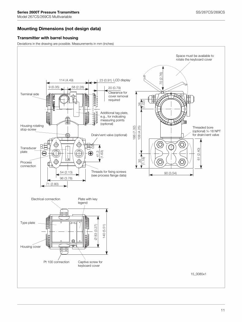
Mounting Dimensions (not design data)
Transmitter with barrel housingDeviations in the drawing are possible. Measurements in mm (inches)
140
(5.5
1)
∅83
(3.2
7)
54 (2.13)
96 (3.78)
41.3
(1.6
3)
9 (0.35) 58 (2.28)
114 (4.49) 23 (0.91)
20 (0.79)
71 (2.80)
70 (2
.76)
26(1
.02)
186
(7.3
2)
108
(4.2
5)30
(1.1
8)
90 (3.54)
61 (2
.40)
+-
Terminal side
Space must be available to rotate the keyboard cover
Threaded bore (optional) ¼-18 NPTfor drain/vent valve
Additional tag plate, e.g., for indicating measuring points (optional)
LCD display
Clearance for cover removal required
Housing rotatingstop-screw
Transducer plate
Process connection
Threads for fixing screws (see process flange data)
Electrical connection
Type plate
Housing cover
Captive screw for keyboard cover
Plate with key legend
Pt 100 connection
Drain/vent valve (optional)
11
15_0085x1

Series 2600T Pressure Transmitters SS/267CS/269CSModel 267CS/269CS Multivariable
Transmitter with DIN housingDeviations in the drawing are possible. Measurements in mm (inches)
43(1.69)
140
(5.5
1)
70 (2.76)
83 (3
.27)
61 (2.40)
107 (4.21)
138 (5.43)
168 (6.61)
20 (0.79)
23 (0.91)
90 (3
.54)
54 (2.13)
96 (3.78)
41.3
(1.6
3)
48 (1.89)27 (1.06)20 (0.79)
Terminal side
Space must be available to rotate the keyboard cover
Additional tag plate, e.g., for indicating measuring points (optional)
Housing rotating stop-screw
Transducer plate
Process connection
Threads for fixing screws (see process flange data)
Electrical connectionType plate
Housing cover
Captive screw for keyboard cover
Plate with key legend
Electrical connection
LCD display
15_0086x1
Pt 100 connection
12
139 (5.47) Clearance for cover removal required

Series 2600T Pressure Transmitters SS/267CS/269CSModel 267CS/269CS Multivariable
Mounting options with bracketDeviations in the drawing are possible. Measurements in mm (inches)
∅10
(0.4
)
60(2.36) 135.5 (5.33)
72 (2.83)
72 (2
.83)
∅ 11 (0.43)
214 (8.43)
56(2.20)
72 (2
.83)
136
(5.3
5)57(2
.24)
110 (4.33)
Vertical pipe mounting Horizontal pipe mounting Vertical pipe mounting and transmitter above the mounting bracket
Horizontal pipe mounting and transmitter above the mounting bracket
M01517x1
13
M01521x1M01520x1
M01519x1M01518x1

Series 2600T Pressure Transmitters SS/267CS/269CSModel 267CS/269CS Multivariable
Electrical connections
Standard terminal block
Harting Han 8D (8U) connector
14 12
1113- -+ +TEST SIGNAL
Grounding/potential equalizing terminal Output signal/power supplyTest sockets for 4 to 20 mA
(not with Fieldbus transmitters)
Cable entry
Connection for Pt 100
1
2 4
3
1
2
3
4
Mating plug (socket) not supplied
Pin (male) assignmentNumber FOUNDATION
FieldbusPROFIBUS PA
1234
FF-FF+
ShieldGround
PA+Ground
PA shield
7/8 in connector
M12 x 1 connector
Fieldbus plug connector
15_0066x1
Pt 100 cable entry
M01450x1
Screw terminals for leads with 0.5 to 2.5 mm² cross-section
21
- +Harting Han 8D (8U) pin assignment (socket view)
DIN housing Barrel housing
14
15_0079x1

Contactos/Contacts:
Comercial/Commercial:
Fernando Mena Costa
e-mail: fcosta@bhb,pt
Tel: (+351) 21 843 64 00
Fax: (+351) 21 843 64 09
Assistência/Service:
Patricia Costa
e-mail: [email protected]
Tel: (+351) 21 843 64 00