SPS-9600/9602 High Current Switching Mode Power … High Current Switching Mode Power Supply with...
4
SPS-9600/9602 High Current Switching Mode Power Supply with Remote Sensing & Control User Manual 1. INTRODUCTION This 900W switching mode DC regulated dual output power supply series provides high current with constant current limiting protection. It has a variable output: 1~ 15Vdc for SPS-9600 & 1~30Vdc for SPS-9602. It is designed with a high efficient Active Power Factor Corrector. The remote sensing terminal is used to compensate for long output line losses.The output voltage level can be externally controlled via the remote control terminal. 2. PRECAUTIONS ● Never Short the Remote Sensing Terminal ● This power supply is for Indoor Use Only. ● Do not expose the power supply to sun, high humid and dusty environment. ● Never remove the metal cover of the power supply while AC power is connected. ● Never touch the unit when your hands are wet. ● Never block the ventilation slots and cooling fan air intake window ● Never attempt to repair the power supply. Incorrect re-assembly may result in a risk of electric shock or fire. ● Never use the power supply for the load requiring higher current than the designed value otherwise it may damage the power supply. ● Place the power supply on a flat surface with sufficient clearance, dry, dust free surroundings for ventilation. 3. CONTROLS AND INDICATORS (1) Voltage & Ammeter LED Display (2) Overload LED Indicator – Overload(Constant Current Limiting) & Short-Circuit Protection (3) Output Voltage Control Knob(control both main and auxilary output) (4) Power ON/OFF Switch (5) Power ON/OFF LED (6) Auxiliary Output Terminal (Rated 5A for SPS-9600 / Rated 3A for SPS-9602) (7) Main Output Terminal (Rated 60A for SPS-9600 / Rated 30A for SPS-9602) Note : SPS-9600 : The Total Rated Current(Aux. + Main) is 60A SPS-9602 : The Total Rated Current(Aux. + Main) is 30A (8) Remote Sensing Terminal (Warning! : Never short the remote sensing terminal) (9) Remote Control Terminal (10) Remote Control ON/OFF Switch (11) Cooling Fan Air Intake Grille (12) AC Input Plug Front Rear Note: Main and Auxiliary output give out same output voltage CAUTION! : The AC Input is DOUBLE POLE FUSING
Transcript of SPS-9600/9602 High Current Switching Mode Power … High Current Switching Mode Power Supply with...
SPS-9600/9602 High Current Switching Mode Power Supply with Remote Sensing & Control
User Manual
1. INTRODUCTION
This 900W switching mode DC regulated dual output power supply series provides high current withconstant current limiting protection. It has a variable output: 1~ 15Vdc for SPS-9600 & 1~30Vdc forSPS-9602. It is designed with a high efficient Active Power Factor Corrector. The remote sensing terminal isused to compensate for long output line losses.The output voltage level can be externally controlled via theremote control terminal.
2. PRECAUTIONS
● Never Short the Remote Sensing Terminal● This power supply is for Indoor Use Only.● Do not expose the power supply to sun, high humid and dusty environment.● Never remove the metal cover of the power supply while AC power is connected.● Never touch the unit when your hands are wet.● Never block the ventilation slots and cooling fan air intake window ● Never attempt to repair the power supply. Incorrect re-assembly may result in a risk of electric shock or
fire.● Never use the power supply for the load requiring higher current than the designed value otherwise it
may damage the power supply.● Place the power supply on a flat surface with sufficient clearance, dry, dust free surroundings for
ventilation.
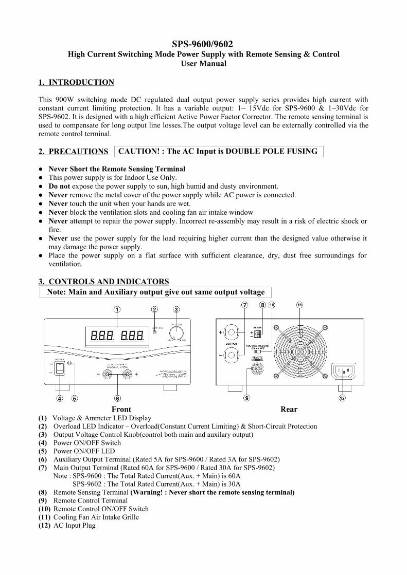
3. CONTROLS AND INDICATORS
(1) Voltage & Ammeter LED Display(2) Overload LED Indicator – Overload(Constant Current Limiting) & Short-Circuit Protection(3) Output Voltage Control Knob(control both main and auxilary output)(4) Power ON/OFF Switch(5) Power ON/OFF LED(6) Auxiliary Output Terminal (Rated 5A for SPS-9600 / Rated 3A for SPS-9602)(7) Main Output Terminal (Rated 60A for SPS-9600 / Rated 30A for SPS-9602)
Note : SPS-9600 : The Total Rated Current(Aux. + Main) is 60ASPS-9602 : The Total Rated Current(Aux. + Main) is 30A
(8) Remote Sensing Terminal (Warning! : Never short the remote sensing terminal)(9) Remote Control Terminal(10) Remote Control ON/OFF Switch(11) Cooling Fan Air Intake Grille(12) AC Input Plug
Front Rear
Note: Main and Auxiliary output give out same output voltage
CAUTION! : The AC Input is DOUBLE POLE FUSING

4. CONNECTION 4.1 This series has 2 models. Make sure you have purchased the correct one.
They have different output voltage range and current as following:Model Number Output Voltage Range Total Rated Current (Main+Auxiliary)
SPS - 9600 1 ~ 15V 60A
SPS - 9602 1 ~ 30V 30A
4.2 Check the rating label of the power supply and make sure it complies with your AC mains voltage. Connect the power supply to the AC Mains using the provided power cord.
Steps 4.3 & 4.4 explain how to use the special features: remote sensing and remote control.You can use the 2 features at the same time or separately.Please go to step 4.5 if you do not use the 2 features and make sure the remote controlON/OFF switch is in OFF position(rear panel).
4.3 REMOTE SENSING – Take note of the warning and follow the order of installation. Warning!:Never short the Remote Sensing Terminal
Connection: 1. First complete the power connections between power supply and equipment. 2. Check and make sure the power connections are secure. 3. Then make connections between Remote Sensing and equipment. Warning!:Never short the Remote Sensing Terminal
Dis-connection: 1. First disconnect the remote sensing connections. 2. Then disconnect the power connections between the power supply and equipment.
Fig 3 showing connections between Remote Sensing, Power output and Equipment.
The remote sensing wire should be AT LEAST 22AWG wire size.
4.4 REMOTE CONTROL4.4.1 VOLTAGE REMOTE CONTROLSet up the provided remote connector plug(a) Remove the black portion of the remote control connector plug by removing the screw as Fig 4.
Black portion
Silver portion Fig. 42. Rotate the black portion1. Remove the screw

(b) Solder 3 wires(22AWG) to PORT 1, 2 & 3 of black portion as shown in Fig.5.
(c) Make sure the load is disconnected and the power supply is OFF.(d) Plug the remote connector plug into the remote control terminal of the power supply.(e) Secure the remote connector plug to the terminal socket by locking connector ring(Fig 6).
Then, you can choose either method A or B below to use the remote control feature:
Method A : Using External Voltage SourceA variable external voltage source of 0 ~ 5V is fed into the remote control terminal toadjust the output voltage level of both Main and Auxiliary output.
Warning! : Do not input higher than 5V, otherwise the OverVoltage Protection(OVP) will be triggered.
A (i) Make sure the load is disconnected and the power supply is OFF. (ii) Use ONLY wires from port 2 and 3. Then, connect port 2 to positive polarity of the external
voltage source and port 3 to negative polarity of the external voltage source. (iii) Turn the Remote Control ON/OFF Switch to ON position. (iv) Switch on the power supply.
(v) Vary the external input voltage 0 – 5V to check and verify for the full output voltage range of power supply.
(vi) Switch off the power supply.
Method B: Using Internal Voltage SourceB (i) Make sure the load is disconnected and the power supply is OFF. (ii) Prepare a 5kohm variable resistor and use wires from port 1, 2 and 3 as shown in Fig.7.
(iii) Turn the the Remote Control ON/OFF Switch to ON position.(iv) Switch on the power supply.(v) Adjust the 5kohm variable resistor from one end to other end to check and verify for the full output voltage range of power supply.(vi) Switch off the power supply.
Outer ring
Fig. 6
Fig. 5
Port numbers are marked on the black portion
To Port 1
To Port 2
To Port 3
4.4.2 ENABLE AND DISABLE THE OUTPUTYou can use Port 7 and 8 to remote control the OUTPUT ON/OFF.
a) Open Port 7 and 8 if you want to ENABLE the output ( By default ) b) Short Port 7 and 8 if you want to DISABLE the output.
4.5 If you do not use the remote control feature, make sure the remote control ON/OFF switch is in OFFposition(Rear panel).
4.6 Switch on the power supply and the power ON/OFF LED should light up in green. Then, adjust the output voltage to the desired voltage and switch off the power supply. 4.7 Connect the equipment to the power supply. Red (+) is connected to the positive polarity input of the
equipment and Black (-) is connected to the negative polarity input of the equipment.
4.8 Switch on the power supply first and the LED Indicator should light up in green. 4.9 Switch on the equipment and the LED Indicator should still remain in green.
4.10 You can now operate the equipment.When an operation is finished, switch off the equipment first and then switch off the power supply.
4.11 When disconnecting the power supply from the unit, disconnect the remote sensing wire first, thendisconnect the output cables.
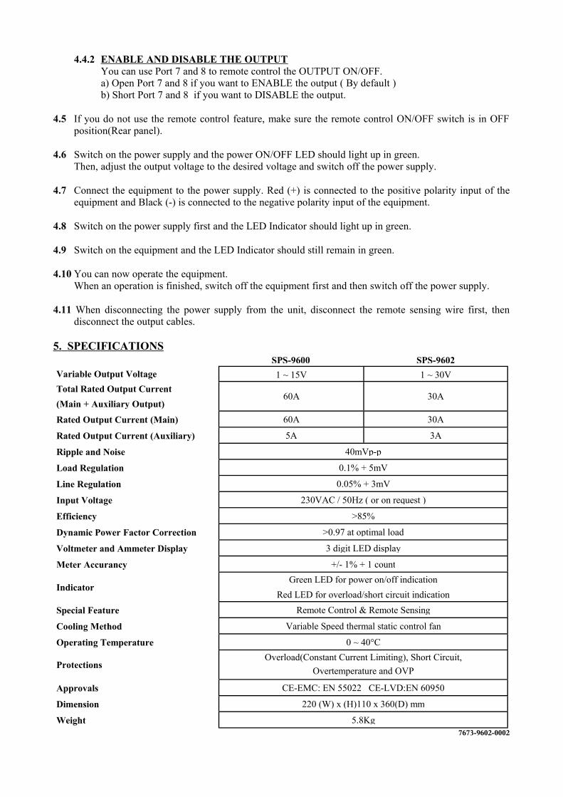
5. SPECIFICATIONS SPS-9600 SPS-9602
Variable Output Voltage 1 ~ 15V 1 ~ 30VTotal Rated Output Current(Main + Auxiliary Output)
60A 30A
Rated Output Current (Main) 60A 30A
Rated Output Current (Auxiliary) 5A 3A
Ripple and Noise 40mVp-p
Load Regulation 0.1% + 5mV
Line Regulation 0.05% + 3mV
Input Voltage 230VAC / 50Hz ( or on request )
Efficiency >85%
Dynamic Power Factor Correction >0.97 at optimal load
Voltmeter and Ammeter Display 3 digit LED display
Meter Accurancy +/- 1% + 1 count
IndicatorGreen LED for power on/off indication
Red LED for overload/short circuit indication
Special Feature Remote Control & Remote Sensing
Cooling Method Variable Speed thermal static control fan
Operating Temperature 0 ~ 40°C
ProtectionsOverload(Constant Current Limiting), Short Circuit,
Overtemperature and OVP
Approvals CE-EMC: EN 55022 CE-LVD:EN 60950
Dimension 220 (W) x (H)110 x 360(D) mm
Weight 5.8Kg7673-9602-0002


![Chap 5 Telecom Switching [Compatibility Mode] - Copy.pdf](https://static.fdocuments.us/doc/165x107/577cd7061a28ab9e789dda1b/chap-5-telecom-switching-compatibility-mode-copypdf.jpg)