Sprint 2 ALU Manual RevA.pdf · Fiber Inspection and Testing Procedures Alcatel-Lucent (ALU) ......
24
Sprint 2.5 Fiber Inspection and Testing Procedures Alcatel-Lucent (ALU) Optical Design Manufacturing, Inc. Technical Support Document
Transcript of Sprint 2 ALU Manual RevA.pdf · Fiber Inspection and Testing Procedures Alcatel-Lucent (ALU) ......

Sprint 2.5
Fiber Inspection and Testing Procedures
Alcatel-Lucent (ALU)
Optical Design Manufacturing, Inc.
Technical Support Document

2
Table of Contents
I. Introduction...................................................................................................
II. Test Site Overview.........................................................................................
III. Equipment....................................................................................................
IV. Fiber Optic Endface Inspection and Cleaning...............................................
V. dB Loss Testing.............................................................................................
VI. Closeout Documentation.............................................................................
VII. Technical Support and FAQ........................................................................
3
4
5
7
16
21
24

3
I. IntroductionThis document will serve as a guide to perform the testing procedures for the fiber optic portion of the Sprint Alcatel-Lucent (ALU) 2.5 GHz cellular tower build. Technicians will utilize equipment from Optical Design Manufacturing to inspect, clean, and save images of fiber endfaces, as well as test for light loss on the optical cables.
This user guide contains the following sections:
• “Test Site Overview” describes the layout of the optical fibers in the cellular tower installation.
• “Equipment” provides detailed information on the TTK 650 Test kit and how to use it for the Sprint ALU 2.5 GHz installation.
• “Fiber Optic Endface Inspection and Cleaning” outlines the steps taken to ensure endface quality prior to testing installed systems.
• “dB Loss Testing” describes how to test the dB loss of the trunk cable and the full system.
• “Closeout Documentation” explains how to save and report images and loss values.
• “Technical Support and FAQ” provides contact information for ODM technical support and answers several frequently asked questions.
4
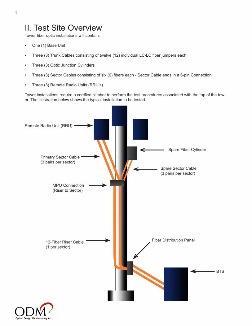
Remote Radio Unit (RRU)
II. Test Site Overview
Spare Fiber Cylinder
Fiber Distribution Panel
BTS
12-Fiber Riser Cable (1 per sector)
Primary Sector Cable(3 pairs per sector)
Tower fiber optic installations will contain:
• One (1) Base Unit
• Three (3) Trunk Cables consisting of twelve (12) individual LC-LC fiber jumpers each
• Three (3) Optic Junction Cylinders
• Three (3) Sector Cables consisting of six (6) fibers each - Sector Cable ends in a 6-pin Connection
• Three (3) Remote Radio Units (RRU’s)
Tower installations require a certified climber to perform the test procedures associated with the top of the tow-er. The illustration below shows the typical installation to be tested.
MPO Connection(Riser to Sector)
Spare Sector Cable(3 pairs per sector)

5
This section provides details on the equipment required to perform the following tasks associated with the Sprint ALU 2.5 installation:
• System dB loss
• Portable video inspection of all optical fiber connectors
• Complete endface cleaning of all connector interfaces
• Closeout documentation
III. Equipment
TTK 650 Test Kit

6
TTK 650 Test Kit - Bill of Materials
MODEL DESCRIPTION APPLICATION QTY.DLS 355 Dual Laser Source 1310nm/1550nm SC Conn. Single mode fiber light source for dB loss testing 1RP 460 Power Meter w/ Zero dB/Set Ref, 1000 data point
store & USB download to OpTest SoftwarePower meter used with light source for dB loss measurement and storage, and USB transfer to PC for closeout documentation
1
VIS 400 Video Inspection Scope w/USB and InSpec™Software, LC, SC, 1.25mm and 2.5mm adapter tips included
Portable connector inspection device to view connector endfaces and ensure connectors meet IEC standard after proper cleaning
1
TAB 008 Dell Tablet (or equivalent)with Case and Charger Allows for touch-based fiber endface inspection with the VIS 400 HDP probe and inSpec application
1
AC 029 LC Adapter for RP460 Optical Power Meter Allows LC connection to optical power meter 1AC 300 CR2 Battery Kit / 5 per pack Spare Battery Kit 1AC 523 LC-clipped LC-SC, SM, 9/125 Fiber, 1 Meter Cable Fiber patch cord to allow calibration of test instruments for
complete system dB loss test1
AC 4500 SM Loopback with Lanyard Allows for calibration of equipment and test of loopback installations
1
VF 610 635nm Red Laser Allows user to observe bends and breaks in optical fiber 1AC 602 LC-LC Adapter LC adapter to allow access to LC duplex connector on Optical
Jumper Cable1
AC 805 Micro USB Cable Stream live images of fiber endfaces from VIS 400 to Dell Tablet for endface inspection and closeout documentation
1
CK 092 SqR Pad with Fiber Wash Pen Wet/Dry cleaning system for connector endfaces 1AC 089 One Click Connector Cleaner For LC connector ends and bulkheads for quick “dry” clean
only1
AC 015 Pelican Style Hard Carry Case Large protective carrying case for all instruments and accessories
1
AC 807 Accessory Kit for TTK 650 - Sprint ALU 2.5
MODEL DESCRIPTION APPLICATION QTY. DLS 350 Dual LED Source 850nm/1300nm SC Conn Multimode light source for dB loss testing 1 AC 4600 LC-clipped LC-SC, MM, 50/125 Fiber, 1 Meter
CableFiber patch cord to allow calibration of test instruments for complete system dB loss test
1
AC 533 MM Loopback with Lanyard Allows for calibration of equipment and test of loopback installations
1
AC 176 MPO Inspection Tip Allows inspection of MPO-style connectors 1AC 083 MPO One-Click Cleaner For MPO connector ends and bulkheads, quick “dry” clean 1
AC 830 Accessory Kit - Sprint ALU 2.5
MODEL DESCRIPTION APPLICATION QTY. AC 830 Male/Female MPO 12 Fiber - Pigtailed LC Pairs
MM Patch CablesMultimode patch cables to allow calibration of test equipment and pre-test of riser/sector cables
1

7
IV. Fiber Optic Endface Inspection and Cleaning
Contamination of fiber connector surfaces is the top reason for link failure in the installation of optical fibercable. It is imperative for installers and technicians to follow the guidelines in this section in order to ensure thequality of the connector endface prior to testing installed systems.
The following inspection and cleaning procedures should be used before installing or testing any fiber optic jumper or trunk cable. Only use approved test sets, inspection equipment, and cleaning supplies. Any move-able debris on a fiber optic connector endface is not allowed. After three dry cleaning attempts to remove debris, a “wet/dry” cleaning process is recommended. Pass or Fail ratings on fibers are determined according to the IEC document 61300-3-35 Ed 1.0.
CleaningThe inSpec software offers automated pass/fail of fiber endfaces when receiving images from the VIS 400inspection scope. Inspect fiber endfaces to determine viability; always clean until all moveable debris is clearand endface is as clean as possible.
Before Cleaning After Cleaning
Auto-analyzed images from VIS 400 using inSpec software

8
Dry Cleaning
One-click cleaner - Push fiber ends into the adapter on the one-click cleaner until the unit clicks. For fibers in-side bulkheads, remove plastic cap from one-click cleaner and insert into the bulkhead opposite the fiber. Push until unit clicks.
Cletop cleaner - Using the lever on the side of the unit, retract the sliding door to reveal the lint-free wipe. Press the fiber endface into the top of the wipe and drag downward with moderate pressure.
Wet/Dry Cleaning
SqR pad and fiber wash pen - Isolate a lint-free wipe using the attached card, then apply a coin-sized spot of cleaning solution to the top of the wipe using the fiber wash pen. Press the fiber endface into the wet spot on the wipe, then drag the fiber downward to the dry portion of the wipe, applying moderate pressure.
NOTE: To verify the most recent test, inspection, and closeout documentation requirements, or if cleaning does not produce acceptable results, contact your construction manager or follow the appropriate Sprint 2.5 escalation procedure.
LC MPO

9
Inspection
Installations will require the inspection and grading of all fiber ends in the riser and sector cables to comply with IEC 61300-3-35. Technicians will archive all riser and sector fiber ends as a pre-test when required. Saving im-ages is vital to the correct documentation of services rendered for the customer; saved images may be needed for future troubleshooting.
1. To connect the VIS 400 to the tablet, plug the micro USB adapter cable into the tablet’s micro USB port, then plug the VIS 400 into the USB 2.0 port on the adapter cable. To connect the VIS 400 to a PC, simply plug the VIS 400 into a USB 2.0 port on the computer.
2. Open the inSpec software and navigate to the “Test Settings” tab at the top of the window. Set theAnalysis Mode to Automatic, the Fiber Type to Multi Mode, and the IEC Profile to Multi Mode PC, asshown below. The VIS 400 will show up in the Video Source drop-down menu under “ODM HDP Probe”or “USB 2.0 Camera”.
3. To save site location and other data along with images, navigate to the “Report Settings” tab in inSpec and fill out all of the fields in the window. This information will be available in VIS reports.
4. Navigate to the “Main” tab in the inSpec window.

10
5. The 1.25mm inspection tip for the VIS 400 will be used to inspect individual fibers in LC pairs, as shown below. The LC pairs will be located:
-At both ends of the cables running from BTS to Fiber Distribution Panel -At the bottom-end of the riser cable -At the radio-end of the primary and spare sector cables
6. Use the focus wheel on the VIS 400 probe to obtain a focused image in the inSpec window. The blue barbelow the image window indicates the current focus level. A higher focus will give a clearer image.
Focus Method

11
7. Touch or click the Analyze button to the left of the image to begin the auto pass/fail analysis.
8. When the analysis has finished, inSpec will display a still image of the fiber endface with a green PASS orred FAIL marker in the top left corner. If the fiber end does not pass automatic analysis, clean the fiber,re-focus the image, and try again.
9. If the image receives a PASS, touch or click the button that reads “Capture Image,” just under theanalyze button. A “Save As” dialogue box will pop up. At this point, you can create a new folder in whichto save the images. It is a good idea to name the folder with the location information to helpdifferentiate between sites.
10. Naming images can be accomplished using your preferred naming convention. Naming methods should allow technicians to match images with fibers. Due to the high volume of fiber endfaces in the Sprint ALU 2.5 build, it will be necessary to separate endface images into folders based on their location on the tower so they may be found easily in the future.
A suggested naming method is as follows:
Place images for BTS Cables, Riser Cables, and Sector Cables in separate folders.
Name BTS Cables according to their sector, pair #, and pair side [(Sector)(Pair#)(A or B)] Ex: Alpha1A, Gamma3B
Name Riser Cables according to their sector, color, and pair side [(Sector)(Color)(A or B)] Ex: Beta-RedA, Gamma-PurpleB
Name Sector Cables according to their sector, color, and pair side [(Sector)(Color)(A or B)] Ex: Alpha-BlueA, Beta-YellowB
12
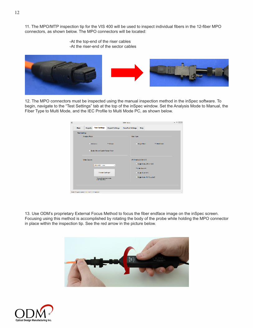
11. The MPO/MTP inspection tip for the VIS 400 will be used to inspect individual fibers in the 12-fiber MPO connectors, as shown below. The MPO connectors will be located:
-At the top-end of the riser cables -At the riser-end of the sector cables
12. The MPO connectors must be inspected using the manual inspection method in the inSpec software. To begin, navigate to the “Test Settings” tab at the top of the inSpec window. Set the Analysis Mode to Manual, the Fiber Type to Multi Mode, and the IEC Profile to Multi Mode PC, as shown below.
13. Use ODM’s proprietary External Focus Method to focus the fiber endface image on the inSpec screen. Focusing using this method is accomplished by rotating the body of the probe while holding the MPO connector in place within the inspection tip. See the red arrow in the picture below.

13
14. An example of a focused MPO connection is shown above. The procedures outlined in Steps 15 through 20 must be completed for every three core/cladding areas seen on the MPO endface (4 times per connector). To scroll along the line of fibers on the MPO endface, use the lever on the MPO/MTP inspection tip, as shown below.
15. Obtain a clear, focused image of three fiber endfaces on the MPO connector.
16. Click the “Show” button on the left side of the inSpec window to bring up the grading circles. Right-click in the middle of the core on the first fiber endface to place the circles. The arrow keys on the keyboard can be used to move the circles around until they are centered.
17. Adjust the grading circles to match the cladding. To change the size of the grading circles, use the scroll wheel on the mouse. Alternately, the circle size can be adjusted by holding the Ctrl key on the keyboard and using the Up or Down arrow keys. The larger of the two yellow circles must be just outside the cladding zone, and the smaller of the yellow circles must be just inside the cladding zone. See the image on the next page.

14
18. Using the small box labeled “Drag Here,” compare any defects on the fiber endface to the table shown be-low. If the fiber endface contains defects or debris that exceed the acceptable parameters shown in the table, clean the endface and try again.
19. Repeat steps 17 and 18 for the other two fiber endfaces visible on the inSpec screen.
20. If all three fiber endfaces are clean and pass the manual inspection, click the “Pass” button and then click “Capture Image” to save the image of the three connectors.
21. Repeat Steps 15 through 20 for the rest of the fiber endfaces on the MPO connector.

15
22. A suggested naming convention for the MPO/MTP connectors is as follows:
Place images for Riser and Sector Cables in separate folders.
Name Risers based on their sector and which set of three endfaces is shown [(Sector)(1-3; 4-6; 7-9; 10-12)] Ex: Alpha 1-3, Gamma 7-9
Name Sectors based on their sector and which set of three endfaces is shown [(Sector)(1-3; 4-6; 7-9; 10-12)] Ex: Beta 10-12, Gamma 4-6
NOTE: To verify the most recent test, inspection, and closeout documentation requirements, or if cleaning does not produce acceptable results, contact your construction manager or follow the appropriate Sprint 2.5 escalation procedure.

16
V. dB Loss TestingdB loss testing is the process of determining how much light is lost along the length of fibers under test. Techni-cians must use an approved light source and power meter along with appropriate test jumpers to complete the test. This guide will only describe the procedures for testing one sector. The dB loss test procedures outlined below will be performed on the fiber runs for each sector, however.
Technicians will perform two separate sweeps for dB loss readings:
1. All fibers as a pre-test2. Full fiber runs as an on-site test
Pre-Test - BTS Cables
1. Connect the RP 460, DLS 350, AC 533 orange duplex jumper, and AC 4600 loopback module together using an LC bulkhead adapter as shown above.
2. Turn on both the RP 460 and the DLS 350 and set them to a wavelength of 850nm.
3. Put the RP 460 into dBm mode by pressing the dB/dBm key on the unit. The RP 460 should read between -22 and -26 dBm when all fibers are clean and connected correctly.
4. Once the RP 460 is holding a steady reading in dBm mode, hold down the dB/dBm key for four seconds. The RP 460 will switch to dB mode and read 0.00dB. Do not switch the unit back to dBm mode; all testing will be done in dB mode.

17
5. Separate the loopback module from the RP 460 and DLS 350, leaving the orange referencing cables at-tached to the units. The loopback module will be attached the to one end of the BTS pair to be tested, and the RP 460/DLS 350 will be attached to the other end of the same BTS cable using the paired cables.
6. When all jumpers are in the correct position, the loss along the BTS cable will be displayed in dB on the RP 460 screen. This number may not exceed 3.0dB. If this number is between 0 and 3.0dB, move on to the next BTS cable. Readings do not need to be saved at this time. If the number is over 3.0 dB, clean all connections and try again. Negative readings are not acceptable.
7. Continue to perform the dB loss test procedure on each remaining BTS pair.
Pre-Test - Riser/Sector Cables
1. Connect the RP 460, DLS 350, AC 533 orange duplex jumper, AC 830 male and female MPO pigtailed cables and AC 4600 loopback module together using LC bulkhead adapters as shown above. The loopback module and paired orange cable must be attached to the same jacket-color pair on either end of the AC 830 accessory cables.
2. Turn on both the RP 460 and the DLS 350 and set them to a wavelength of 850nm.
3. Put the RP 460 into dBm mode by pressing the dB/dBm key on the unit. The RP 460 should read between -22 and -26 dBm when all fibers are clean and connected correctly.
NOTE: Users should connect to multiple corresponding jacketed pairs in the AC 830 accessory cables in order to find the jacketed pair that gives a dBm reading closest to -20dBm before moving on to step 4. This will ensure the most accurate test results and will help to prevent negative loss readings.

18
4. Once the RP 460 is holding a steady reading in dBm mode, hold down the dB/dBm key for four seconds. The RP 460 will switch to dB mode and read 0.00dB. Do not switch the unit back to dBm mode; all testing will be done in dB mode.
5. Remove the pigtailed referencing cable with the male MPO end (if testing the Riser cable) or the referencing cable with the female MPO end (if testing the Sector) from the test setup shown in step 1.
6. Connect the Riser or Sector cable under test in the place of the cable that was removed in step 5. The final test setup will contain the RP 460/DLS 350 connected to the paired orange referencing cable, one of the pig-tailed AC 830 cables, either the Riser or Sector cable under test, and the loopback module.
7. When all jumpers are in the correct position, the loss along the pair on the Riser or Sector cable will be displayed in dB on the RP 460 screen. This number may not exceed 3.0dB. If this number is between 0 and 3.0dB, move the loopback and RP 460/DLS 350 combination to the next jacketed pair cable. Readings do not need to be saved at this time. If the number is over 3.0 dB, clean all connections and try again. Negative read-ings are not acceptable.
On-Site Test - System
1. Connect the RP 460, DLS 350, AC 533 orange duplex jumper, and AC 4600 loopback module together using an LC bulkhead adapter as shown above.
2. Turn on both the RP 460 and the DLS 350 and set them to a wavelength of 850nm.

19
3. Put the RP 460 into dBm mode by pressing the dB/dBm key on the unit. The RP 460 should read between -22 and -26 dBm when all fibers are clean and connected correctly.
4. Once the RP 460 is holding a steady reading in dBm mode, hold down the dB/dBm key for four seconds. The RP 460 will switch to dB mode and read 0.00dB. Do not switch the unit back to dBm mode; all testing will be done in dB mode.
5. Separate the loopback module from the RP 460 and DLS 350, leaving the orange referencing cables at-tached to the units. The loopback module will be attached the to the top end of the system pair to be tested, and the RP 460/DLS 350 will be attached to the bottom end of the same system cable using the paired cables.
6. When all jumpers are in the correct position, the loss along the sytem pair will be displayed in dB on the RP 460 screen. This number may not exceed 6.0dB. If this number is between 0 and 6.0dB, press the Save button on the RP 460 to save the reading, then move on to the next system pair. If the number is over 6.0 dB, clean all connections and try again. Negative readings are not acceptable.
7. Continue to perform the dB loss test procedure on each remaining system pair.
NOTE: The locations where the test jumpers and loopback module will be inserted to test the system loss will be slightly different depending on the status of the pair under test. Primary pairs will be tested at the RRU and the BTS unit, and Spare pairs will be tested at the spare fiber cylinder and Fiber Distribution Panel. See the diagrams on the next page for a visual representation of these differences.
8. Upload the dB loss readings saved to the RP 460 into the OpTest software from ODM the same day the readings are obtained. For detailed instructions on completing closeout reports, refer to section VI: Closeout Documentation.
20
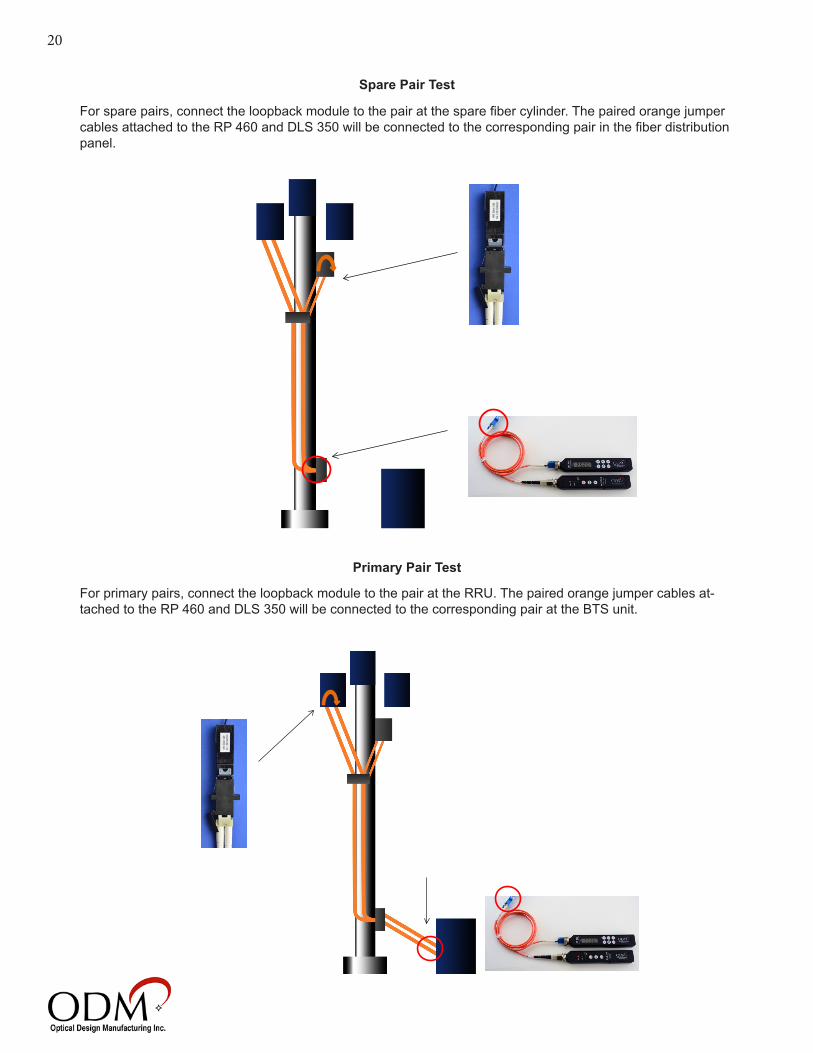
Spare Pair Test
Primary Pair Test
For spare pairs, connect the loopback module to the pair at the spare fiber cylinder. The paired orange jumper cables attached to the RP 460 and DLS 350 will be connected to the corresponding pair in the fiber distribution panel.
For primary pairs, connect the loopback module to the pair at the RRU. The paired orange jumper cables at-tached to the RP 460 and DLS 350 will be connected to the corresponding pair at the BTS unit.

21
VI. Closeout DocumentationOne loss test will be reported when installing fiber on the Sprint ALU 2.5 tower build. This test will be performed on the primary and spare fibers in the system as outlined in section V. The dB loss readings taken on these fiber pairs can be reported easily using ODM’s OpTest software.
1. Connect the RP 460 to a computer using the supplied USB cable.
2. Open the OpTest software and place the software into “Dump” mode by navigating to Settings>Data Mode>Dump Mode.
3. Click Settings>Report Settings to access the Report Settings box. Check “Enable” next to the 850 wave-length to set the software to mark each reading as Pass/Fail on the report. Set the maximum dB loss at 6.0, as shown below.

22
4. In the Report Settings box, select the cable color configuration that corresponds to the loss test that is being reported. When the final report is exported to a spreadsheet, the colors of the cables in the Sprint ALU 2.5 build will populate in the “Comments” section. Click OK to exit Report Settings.
6. Press the USB button on the RP 460. All of the data points saved to the device’s internal memory will appear in the window to the left of the Test Site and Customer Information windows.
5. Fill out the Test Site, Customer. and User information on the right side of the OpTest window. All of this infor-mation will appear in the final closeout report.
7. Click File>Export to Excel to create an Excel file with all of the dB loss readings, cable codes, and testing information included.

23
Sample Closeout Report

24
VIII. Technical Support and FAQ
Frequently Asked Questions
Q. What is the difference between dBm and dB? A. dB (decibel) is a unit used to express values of power level on a logarithmic scale. dBm is an absolute optical power measurement referenced to 1 milliwatt of optical energy. It is the starting measurement of the dB loss measurements.
Q. Why do I get a negative dB reading? A. This reading is often the result of the calibration cables not being as clean and aligned as the cable under measurement. This negative reading is common while measuring short-distance cables (less than 100 feet). Always keep reference patch cables clean and free from contamination. Negative readings greater than -.5dB are indicative of other problems in the measurement. In this case, call our technical support group at (603) 524-8350.
Q. Will my reading be saved in the RP 460 memory while the battery is changed? A. Yes the RP 460 will retain measurements in a non-volatile memory.
Q. Why do I need to inspect all fiber connections? A. Short-distance fiber systems typically fail as a result of contaminated connector ends. More than 90 percent of all failures are due to endface debris. The use of a Video Inspection Scope ensures quality in a connected fiber system.
Technical Support
If you need technical assistance or have specific questions about any procedures or guidelines in this guide, please contact our technical support team:
During Business Hours8AM to 5PM Eastern Standard TimePlease call us at 603-524-8350
Evenings/WeekendsEmail us at [email protected] include your phone number and we will contact you.
On YouTubeVisit our YouTube page for helpful videos
Visit Our Websitewww.odm-inc.com