

Spring 2016 :: 16662 :: Robot Autonomy :: Team 7 Motion Planning for ... · Motion Planning for...
25
Motion Planning for Autonomous All-Terrain Vehicle Guan-Horng Liu, Samuel Wang, Shu-Kai Lin, Chris Wang, Tiffany May Advisor : Mr. George Kantor Spring 2016 :: 16662 :: Robot Autonomy :: Team 7
Transcript of Spring 2016 :: 16662 :: Robot Autonomy :: Team 7 Motion Planning for ... · Motion Planning for...

Motion Planning for Autonomous All-Terrain Vehicle
Guan-Horng Liu, Samuel Wang, Shu-Kai Lin, Chris Wang, Tiffany MayAdvisor : Mr. George Kantor
Spring 2016 :: 16662 :: Robot Autonomy :: Team 7

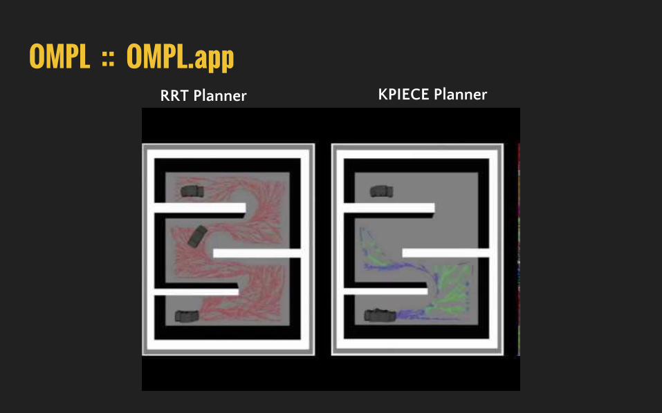
OUTLINE Platform Introduction
Motivation & Challenges
Problem Formulation
OMPL Framework
ROS Planning PipeLine Collision Check Module RRT-Based Planner Module
Final Demo

Platform Introduction Project Overview General purpose autonomous technology development for off-road driving in wilderness environment.
Vehicle Platform 2016 YAMAHA Viking VI side-by-side ATV
On-board Sensors Novatel, Velodyne 64, Multisense S21
Software Modules Classification, Pose Estimation, Global Planner, Local Planner
Parter Field Robotics Center YAMAHA Motor Company, Japan YAMAHA Motor Corporation, USA
GPS/INS
LiDAR
RGBD Camera

Motivation & Challenges
Uncertainty in Vehicle Dynamic Response Modeling e.g. Wheel-terrain interaction...
Real-Time Implementation e.g. Anytime planning, Computational efficiency
Motivation Propose a new local planner for off-road navigation with
▪ Static obstacles avoidance▪ High-speed maneuvering in complex vehicle dynamic
Kinodynamic Planning in Control Space
Challenges

Problem FormulationTesting Scenario Design S-shape maneuvering with static obstacles avoidance Vehicle velocity with at least 20kph Model-based planner
Available Module/Sensor YAMAHA Velocity Controller (YVCA) LiDAR (point cloud), GPS/INS (position & velocity)
55
25
25
25
50
5 5
GOAL
START
1.5
7

Show Time First
OUTLINE Platform Introduction
Motivation & Challenges
Problem Formulation
OMPL Framework
ROS Planning PipeLine Collision Check Module RRT-Based Planner Module
Final Demo

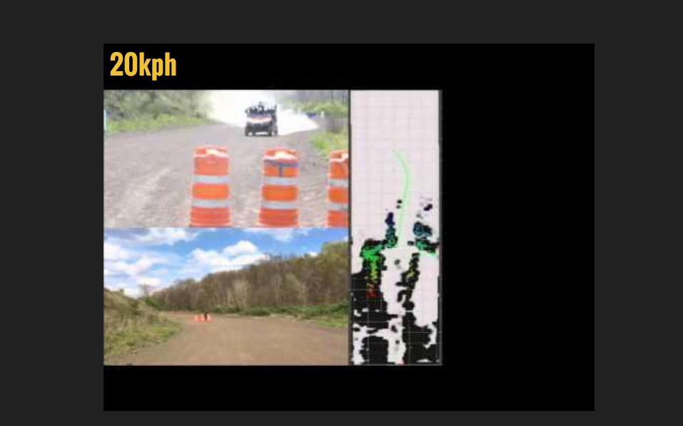
OMPL :: Framework
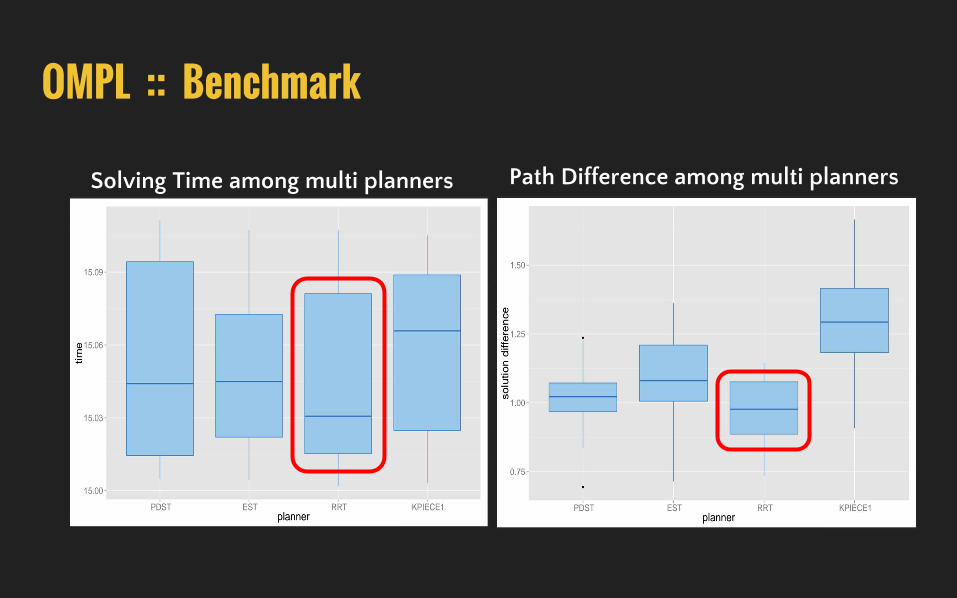
OMPL :: Benchmark
Solving Time among multi planners Path Difference among multi planners

RRT-Based Planner/goalpoint
/odometry
/point_cloud
Rviz/visualization
/vel_command
ROS Planning PipeLine
Collision Check
Velocity Controller
Collision Check Module
Simplified Occupancy Grid
Mesh
RANSAC Segmentation
Height Map Algorithm
Implemented Approach
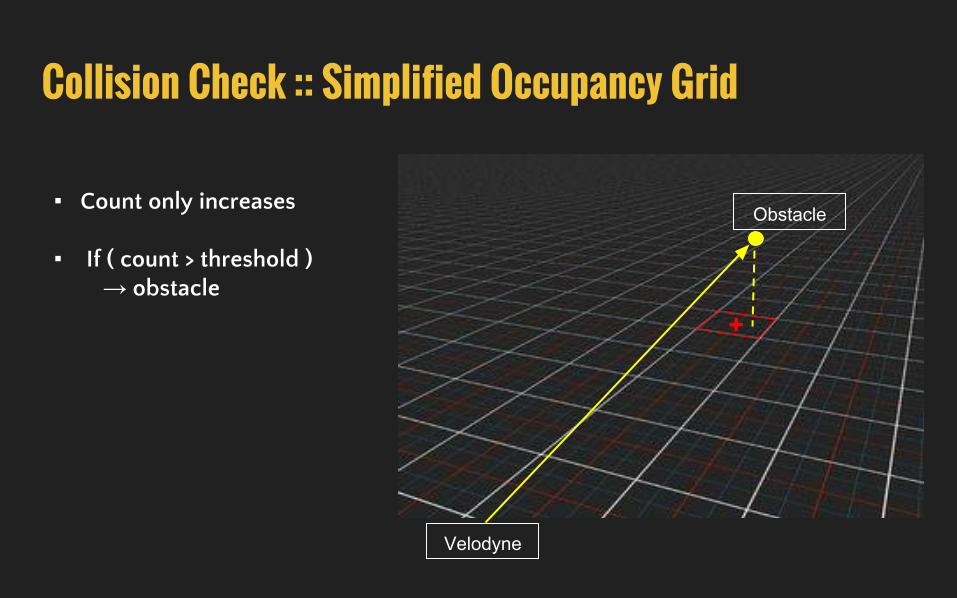
Collision Check :: Simplified Occupancy Grid
Velodyne
Obstacle
+
▪ Count only increases
▪ If ( count > threshold ) → obstacle

o Pitch > threshold
o Roll > threshold
o Mesh interact with the ray
between two wheels
Collision Check :: Mesh ▪ Use Open Dyanmic Engine (ODE) to cast
ray from 4 wheels down to the mesh
▪ Calculate vehicle pitch and roll from 4 contact points
▪ Collision condition:

Collision Check :: RANSAC Segmentation▪ Use RANSAC to obtain a cloud fitting to the plane model
▪ Get point cloud outliers to extract obstacles

Collision Check :: Height Map Algorithm▪ Calculate the height difference of multiple points within one grid
▪ If (height_difference > threshold) → It’s an obstacle
Max height
Min height
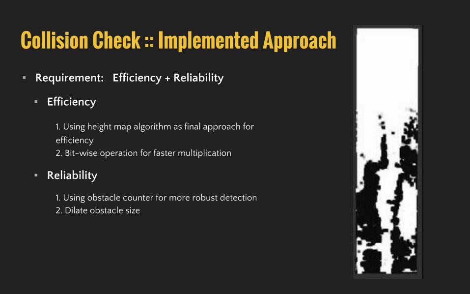
Collision Check :: Implemented Approach▪ Requirement: Efficiency + Reliability
▪ Efficiency
1. Using height map algorithm as final approach for
efficiency
2. Bit-wise operation for faster multiplication
▪ Reliability
1. Using obstacle counter for more robust detection
2. Dilate obstacle size

RRT-Based Planner Design
6 DoF state x
2 DoF control input u = (forward & angular vel.)
SE2 + R3 vehicle-frame velocity
Why RRT ?▪ High dimensional planning w/ complex dynamic
model▪ Smooth maneuvering

RRT-Based Planner Design
6 DoF state x
2 DoF control input u = (forward & angular vel.)
SE2 + R3 vehicle-frame velocity

RRT-Based Planner Design1. Data-Driven Vehicle Dynamic Response Model
2. Control Shooting Method w/ Random Control Duration
Flexible constraints between connect and extend RRTSteering Mechanisum Constraint in Control Space
Extend Connect

RRT-Based Planner Design1. Data-Driven Vehicle Dynamic Response Model
2. Control Shooting Method w/ Random Propagation Steps
3. Sub-Optimization w/ Minimal Traveling Time One more step needed to reach RRT* in control space Connect extened node to minimum node
[1] Jeong hwan Jeon, Emilio Frazzoli, “Anytime Computation of Time-Optimal Off-Road Vehicle Maneuvers using RRT*”
x_extend’
x_nearest
x_min x_extend

RRT-Based Planner Design1. Data-Driven Vehicle Dynamic Response Model
2. Control Shooting Method w/ Random Propagation Steps
3. Sub-Optimization w/ Minimal Traveling Time
4. Replanning Solving loop in 20Hz, planner loop in 2Hz Estimate start state using dynamic model in 1.
Path consistence among each planner loop
Solve Path
Planner Loop
0.05 sec Publish the lowest cost path
Update start, collision map
Solve Path
Planner Loop0.5 sec

Final Demo VideoVehicle operation vel: 10 ~ 40 kphBase line requirement: 20 kphFinal Demo here: ~ 30 kph
30kph