Split Systems Cooling Condensers Divididos... · TTA = Split System Cooling DIGITS 4-6: NOMINAL...
48
Installation Operation Maintenance May 2008 SS-SVX08A-EN Model Numbers: TTA090A***F (60 Hz) TTA075AD**F (50 Hz) TTA155BD**F (50 Hz) TTA120A***F (60 Hz) TTA085AD**F (50 Hz) TTA155CD**G (50 Hz) TTA120B***F (60 Hz) TTA100AD**F (50 Hz) TTA200BD**F (50 Hz) TTA120C***G (60 Hz) TTA100BD**F (50 Hz) TTA150B***F (60 Hz) TTA100CD**G (50 Hz) TTA180B***F (60 Hz) TTA125BD**F (50 Hz) TTA180C***G (60 Hz) TTA240B***F (60 Hz) Split Systems Cooling Condensers 7½ - 20 Tons
Transcript of Split Systems Cooling Condensers Divididos... · TTA = Split System Cooling DIGITS 4-6: NOMINAL...

Installation Operation Maintenance
May 2008 SS-SVX08A-EN
Model Numbers:TTA090A***F (60 Hz) TTA075AD**F (50 Hz) TTA155BD**F (50 Hz)TTA120A***F (60 Hz) TTA085AD**F (50 Hz) TTA155CD**G (50 Hz)TTA120B***F (60 Hz) TTA100AD**F (50 Hz) TTA200BD**F (50 Hz)TTA120C***G (60 Hz) TTA100BD**F (50 Hz)TTA150B***F (60 Hz) TTA100CD**G (50 Hz)TTA180B***F (60 Hz) TTA125BD**F (50 Hz)TTA180C***G (60 Hz)TTA240B***F (60 Hz)
Split Systems Cooling Condensers7½ - 20 Tons
Warnings and Cautions
© 2007 Trane All rights reserved SS-SVX08A-EN
Hazard Identification
Notice that warnings and cautions appear at appropriate intervals throughout this manual. Warnings are provided to alert installing contractors to potential hazards that could result in personal injury or death, while cautions are designed to alert personnel to conditions that could result in equipment damage.
� WARNING
Indicates a potentially hazardous situation which, if not avoided, could result in death
or serious injury.
� CAUTION
Indicates a potentially hazardous situations which, if not avoided, may result in minor
or moderate injury. It may also be used to alert against unsafe practices.
CAUTION
Indicates a situation that may result in equipment or property-damage-only accidents.
Overview of Manual
Note: One copy of this document ships inside the control panel of each unit and is customer property. It must be retained by the unit’s maintenance personnel.
This booklet describes proper installation, operation and maintenance procedures for air cooled systems. By carefully reviewing the information within this manual and following the instructions, the risk of improper operation and/or component damage will be minimized.
It is important that periodic maintenance be performed to help assure trouble free operation. A maintenance schedule is provided at the end of this manual. Should equipment failure occur, contact a qualified service organization with qualified, experienced HVAC technicians to properly diagnose and repair this equipment.
Note: All phases of this installation must comply with the NATIONAL, STATE & LOCAL CODES. In addition to local codes, the installation must conform with National Electric Code -ANSI/NFPA NO. 70 LATEST REVISION.
�WARNING Hazard of Explosion and Deadly Gases!
Contains Refrigerant! Never solder, braze or weld on refrigerant lines or any unit
components that are above atmospheric pressure or where refrigerant may be
present. Always remove refrigerant by following the guidelines established by the EPA
Federal Clean Air Act or other state or local codes as appropriate. After refrigerant
removal, use dry nitrogen to bring system back to atmospheric pressure before
opening system for repairs. Mixtures of refrigerants and air under pressure may
become combustible in the presence of an ignition source leading to an explosion.
Excessive heat from soldering, brazing or welding with refrigerant vapors present can
form highly toxic gases and extremely corrosive acids. Failure to follow all proper safe
refrigerant handling practices could result in death or serious injury.
SS-SVX08A-EN 3
Model Number Description . . . . . . . . . . . . . . . . . . . . . . . . . . . . . . . . . . . . . . . . . 4
General Information . . . . . . . . . . . . . . . . . . . . . . . . . . . . . . . . . . . . . . . . . . . . . . . . 5
Pre-Installation . . . . . . . . . . . . . . . . . . . . . . . . . . . . . . . . . . . . . . . . . . . . . . . . . . . . 7
Dimensional Data . . . . . . . . . . . . . . . . . . . . . . . . . . . . . . . . . . . . . . . . . . . . . . . . . . 9
Electrical Data . . . . . . . . . . . . . . . . . . . . . . . . . . . . . . . . . . . . . . . . . . . . . . . . . . . . 14
Installation . . . . . . . . . . . . . . . . . . . . . . . . . . . . . . . . . . . . . . . . . . . . . . . . . . . . . . . 16
Wiring Diagram . . . . . . . . . . . . . . . . . . . . . . . . . . . . . . . . . . . . . . . . . . . . . . . . . . . 27
Refrigerant Circuit . . . . . . . . . . . . . . . . . . . . . . . . . . . . . . . . . . . . . . . . . . . . . . . . . 29
Pre-Start . . . . . . . . . . . . . . . . . . . . . . . . . . . . . . . . . . . . . . . . . . . . . . . . . . . . . . . . . 30
Start-Up . . . . . . . . . . . . . . . . . . . . . . . . . . . . . . . . . . . . . . . . . . . . . . . . . . . . . . . . . . 32
Service Test Modes ReliaTel™ Controls . . . . . . . . . . . . . . . . . . . . . . . . . . . . . 35
Troubleshooting . . . . . . . . . . . . . . . . . . . . . . . . . . . . . . . . . . . . . . . . . . . . . . . . . . 36
Maintenance . . . . . . . . . . . . . . . . . . . . . . . . . . . . . . . . . . . . . . . . . . . . . . . . . . . . . . 42
Maintenance Log . . . . . . . . . . . . . . . . . . . . . . . . . . . . . . . . . . . . . . . . . . . . . . . . . 44
Warranty . . . . . . . . . . . . . . . . . . . . . . . . . . . . . . . . . . . . . . . . . . . . . . . . . . . . . . . . . 45
Wiring Diagram Matrix . . . . . . . . . . . . . . . . . . . . . . . . . . . . . . . . . . . . . . . . . . . . 47
Table of Contents
4 SS-SVX08A-EN
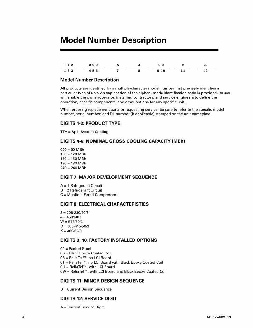
Model Number Description
All products are identified by a multiple-character model number that precisely identifies a particular type of unit. An explanation of the alphanumeric identification code is provided. Its use will enable the owner/operator, installing contractors, and service engineers to define the operation, specific components, and other options for any specific unit.
When ordering replacement parts or requesting service, be sure to refer to the specific model number, serial number, and DL number (if applicable) stamped on the unit nameplate.
DIGITS 1-3: PRODUCT TYPE
TTA = Split System Cooling
DIGITS 4-6: NOMINAL GROSS COOLING CAPACITY (MBh)
090 = 90 MBh 120 = 120 MBh 150 = 150 MBh 180 = 180 MBh 240 = 240 MBh
DIGIT 7: MAJOR DEVELOPMENT SEQUENCE
A = 1 Refrigerant Circuit B = 2 Refrigerant Circuit C = Manifold Scroll Compressors
DIGIT 8: ELECTRICAL CHARACTERISTICS
3 = 208-230/60/3 4 = 460/60/3 W = 575/60/3 D = 380-415/50/3 K = 380/60/3
DIGITS 9, 10: FACTORY INSTALLED OPTIONS
00 = Packed Stock 0S = Black Epoxy Coated Coil 0R = ReliaTel™, no LCI Board 0T = ReliaTel™, no LCI Board with Black Epoxy Coated Coil 0U = ReliaTel™, with LCI Board 0W = ReliaTel™, with LCI Board and Black Epoxy Coated Coil
DIGITS 11: MINOR DESIGN SEQUENCE
B = Current Design Sequence
DIGITS 12: SERVICE DIGIT
A = Current Service Digit
Model Number Description
T T A 0 9 0 A 3 0 0 B A
1 2 3 4 5 6 7 8 9 10 11 12
SS-SVX08A-EN 5
Installation procedures should be performed in the sequence that they appear in this manual. Do not destroy or remove the manual from the unit.
The manual should remain weather-protected with the unit until all installation procedures are complete.
Note: It is not the intention of this manual to cover all possible variations in systems that may occur or to provide comprehensive information concerning every possible contingency that may be encountered during an installation. If additional information is required or if specific problems arise that are not fully discussed in this manual, contact your local sales office.
Note: “Warnings” and “Cautions” appear at appropriate places in this manual. Your personal safety and the proper operation of this machine require that you follow them carefully. The Company assumes no liability for installations or servicing performed by unqualified personnel.
Installation Checklist
An "Installation Checklist" is provided at the end of the installation section of this manual. Use the checklist to verify that all necessary installation procedures have been completed. Do not use the checklist as a substitute for reading the information contained in the manual. Read the entire manual before beginning installation procedures.
Unit Inspection
Inspect material carefully for any shipping damage. If damaged, it must be reported to, and claims made against the transportation company. Compare the information that appears on the unit nameplate with ordering and submittal data to ensure the proper unit was shipped. Available power supply must be compatible with electrical characteristics specified on component nameplates. Replace damaged parts with authorized parts only.
Inspection Checklist
To protect against loss due to damage incurred in transit, complete the following checklist upon receipt of the unit.
1. Inspect individual pieces of the shipment before accepting the unit. Check for obvious damage to the unit or packing material.
2. Inspect the unit for concealed damage before it is stored and as soon as possible after delivery. Concealed damage must be reported within 15 days. If concealed damage is discovered, stop unpacking the shipment. Do not remove damaged material from the receiving location. Take photos of the damage if possible. The owner must provide reasonable evidence that the damage did not occur after delivery.
3. Notify the carrier’s terminal of damage immediately by phone and by mail. Request an immediate joint inspection of the damage by the carrier and the consignee.
4. Notify the sales representative and arrange for repair. Do not repair the unit until the damage is inspected by the carrier’s representative.
Initial Leak Test
All TTA units are shipped with a holding charge of nitrogen in each circuit. Remove the compressor access panel(s) shown in Figure 2, p. 9. Locate the liquid line or suction line service valve for each circuit. Install gauges to determine if the circuits are still pressurized. If not, the charge has escaped. Repair as required to obtain a leak-free circuit.
General Information
6 SS-SVX08A-EN
General Information
Lifting Recommendations
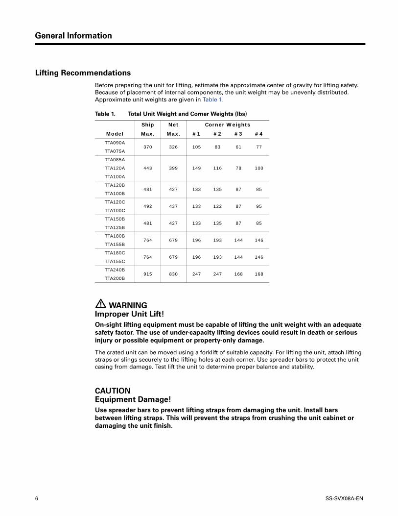
Before preparing the unit for lifting, estimate the approximate center of gravity for lifting safety. Because of placement of internal components, the unit weight may be unevenly distributed. Approximate unit weights are given in Table 1.
Table 1. Total Unit Weight and Corner Weights (lbs)
� WARNING Improper Unit Lift!
On-sight lifting equipment must be capable of lifting the unit weight with an adequate
safety factor. The use of under-capacity lifting devices could result in death or serious
injury or possible equipment or property-only damage.
The crated unit can be moved using a forklift of suitable capacity. For lifting the unit, attach lifting straps or slings securely to the lifting holes at each corner. Use spreader bars to protect the unit casing from damage. Test lift the unit to determine proper balance and stability.
CAUTION Equipment Damage!
Use spreader bars to prevent lifting straps from damaging the unit. Install bars
between lifting straps. This will prevent the straps from crushing the unit cabinet or
damaging the unit finish.
Ship Net Corner Weights
Model Max. Max. #1 #2 #3 #4
TTA090A370 326 105 83 61 77
TTA075A
TTA085A
443 399 149 116 78 100TTA120A
TTA100A
TTA120B481 427 133 135 87 85
TTA100B
TTA120C492 437 133 122 87 95
TTA100C
TTA150B481 427 133 135 87 85
TTA125B
TTA180B764 679 196 193 144 146
TTA155B
TTA180C764 679 196 193 144 146
TTA155C
TTA240B915 830 247 247 168 168
TTA200B
SS-SVX08A-EN 7
Clearances
Provide enough space around the unit to allow unrestricted access to all service points. Refer to Figure 1 through Figure 8, p. 13 for unit dimensions and minimum required service and free air clearances. Observe the following points to ensure proper unit operation.
1. Do not install the unit under a low overhang. Condenser discharge must not be restricted. See Notes in Figure 1 through Figure 8.
Note: Important! Do not obstruct condenser discharge air. This can result in warm air recirculation through the coil.
2. Do not locate the unit in a position where runoff water can fall into the fan discharge openings.
3. Condenser intake air is supplied from three sides of the unit. Adhere to the minimum required clearances given in Figure 1 through Figure 8.
Unit Mounting
Rooftop Mounting
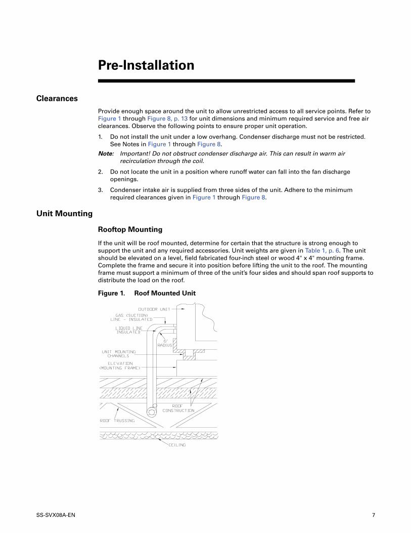
If the unit will be roof mounted, determine for certain that the structure is strong enough to support the unit and any required accessories. Unit weights are given in Table 1, p. 6. The unit should be elevated on a level, field fabricated four-inch steel or wood 4" x 4" mounting frame. Complete the frame and secure it into position before lifting the unit to the roof. The mounting frame must support a minimum of three of the unit’s four sides and should span roof supports to distribute the load on the roof.
Pre-Installation
Figure 1. Roof Mounted Unit
8 SS-SVX08A-EN
Pre-Installation
� WARNING Mounting Integrity!
Ensure that the roof structure supports are strong enough to support the weight of the
unit and any accessories. Failure to do so could result in death or serious injury or
possible equipment or property-only damage.
� WARNING Fiberglass Wool!
Product contains fiberglass wool. Disturbing the insulation in this product during
installation, maintenance or repair will expose you to airborne particles of glass wool
fibers and ceramic fibers known to the state of California to cause cancer through
inhalation. Glass wool fibers may also cause respiratory, skin or eye irritation.
The following warning complies with State of California law, Proposition 65.
Ground Level Mounting
For ground level installation, the unit base should be adequately supported and hold the unit near level. The installation must meet the guidelines set forth in local codes. The support should extend two inches beyond the unit base channels at all points. The unit and support must be isolated from any adjacent structure to prevent possible noise or vibration problems. Any ground level location must comply with required clearances given in Figure 1, p. 7 through Figure 8, p. 13.
Refrigerant Piping
Structural Preparation
Holes must be made in the structure to run refrigerant lines. For the majority of ground-level installations, the holes can be made in the header that rests on top of the foundation. Alternatively, these holes may also be made in the foundation itself. On roof-mounted units, refrigerant lines should enter the building as close to the unit as possible; preferably within three to four inches of the refrigerant connection on the unit, plus a 6-inch (long radius) 90° ell entering the building, Figure 1, p. 7. See Figure 2, p. 9 through Figure 8, p. 13 for unit dimensions and minimum clearances.
SS-SVX08A-EN 9
Dimensional Data
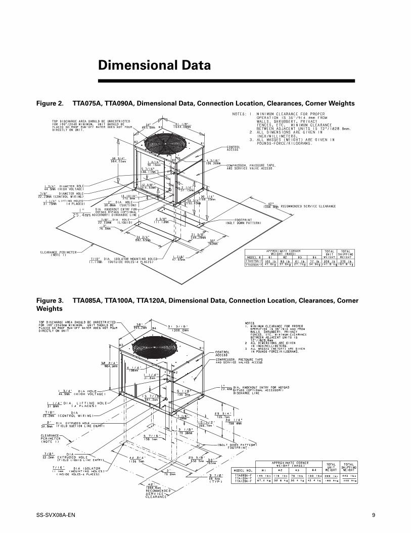
Figure 2. TTA075A, TTA090A, Dimensional Data, Connection Location, Clearances, Corner Weights
Figure 3. TTA085A, TTA100A, TTA120A, Dimensional Data, Connection Location, Clearances, Corner
Weights

10 SS-SVX08A-EN
Dimensional Data
Figure 4. TTA100B, TTA120B, TTA125B, TTA150B, Dimensional Data, Connection Location, Clearances,
Corner Weights
Figure 5. TTA100C, TTA120C, Dimensional Data, Connection Location, Clearances, Corner Weights
SS-SVX08A-EN 11
Dimensional Data
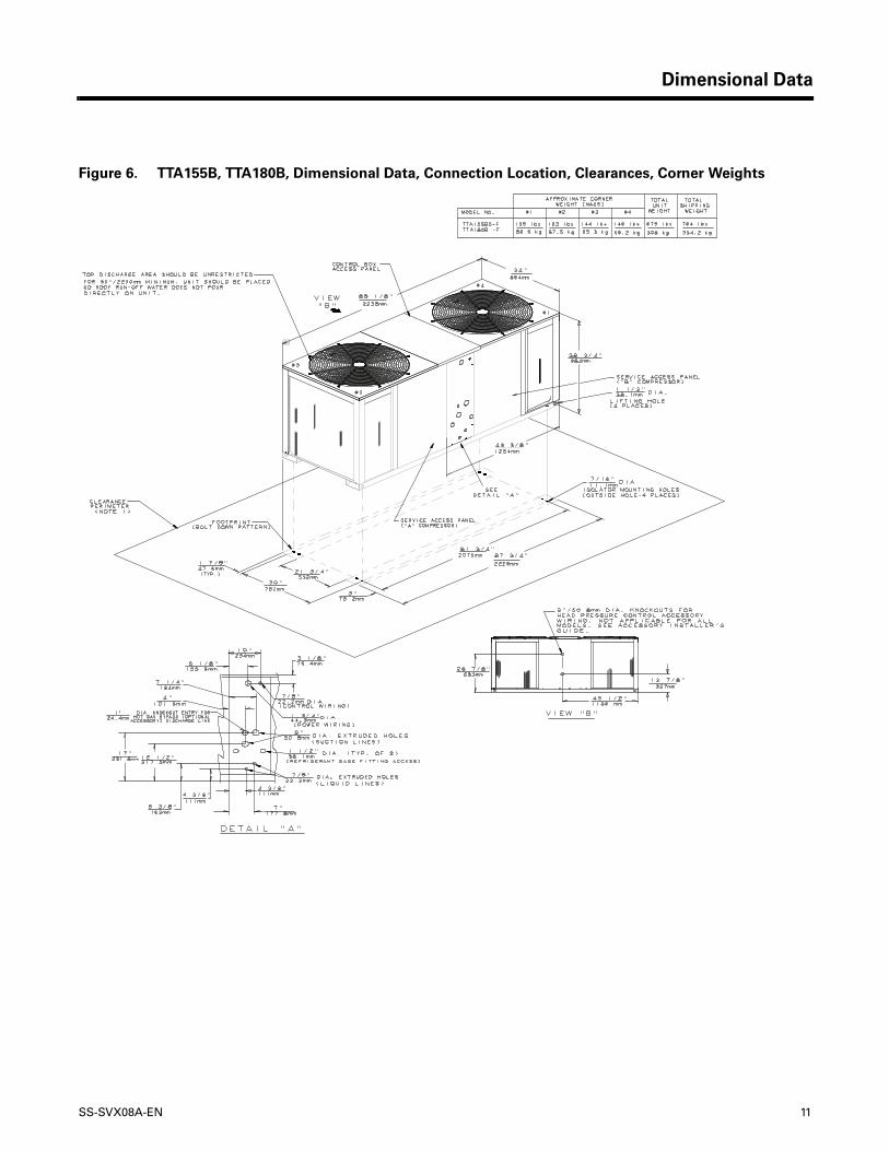
Figure 6. TTA155B, TTA180B, Dimensional Data, Connection Location, Clearances, Corner Weights
12 SS-SVX08A-EN
Dimensional Data
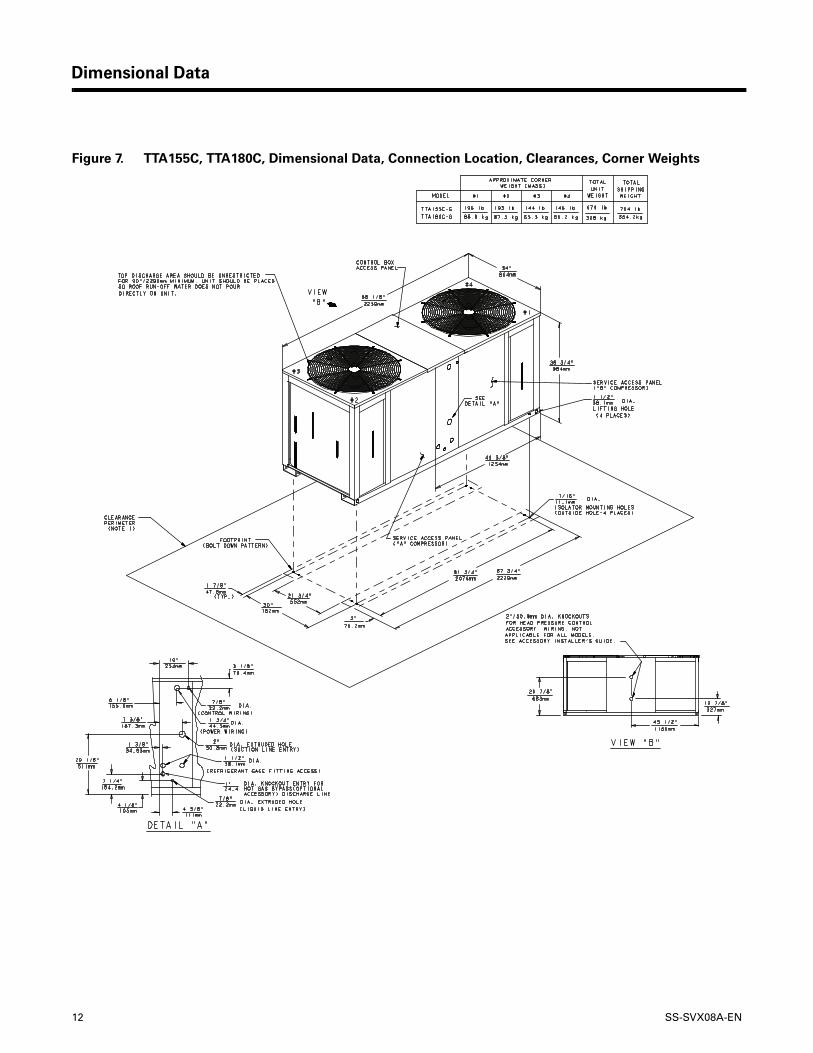
Figure 7. TTA155C, TTA180C, Dimensional Data, Connection Location, Clearances, Corner Weights
SS-SVX08A-EN 13
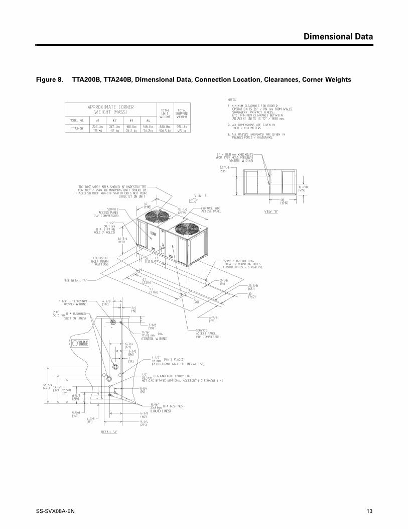
Dimensional Data
Figure 8. TTA200B, TTA240B, Dimensional Data, Connection Location, Clearances, Corner Weights
14 SS-SVX08A-EN
Electrical Data
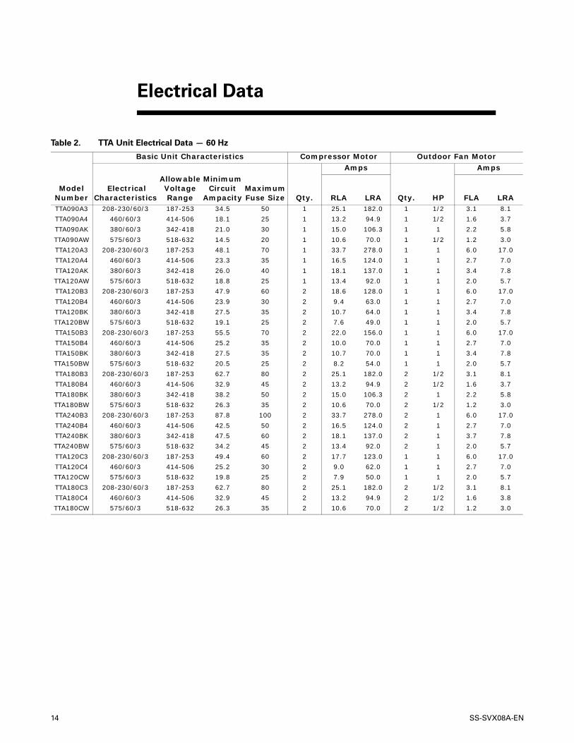
Table 2. TTA Unit Electrical Data — 60 Hz
Model Number
Basic Unit Characteristics Compressor Motor Outdoor Fan Motor
Qty.
Amps
Qty. HP
Amps
ElectricalCharacteristics
AllowableVoltageRange
Minimum Circuit
AmpacityMaximum Fuse Size RLA LRA FLA LRA
TTA090A3 208-230/60/3 187-253 34.5 50 1 25.1 182.0 1 1/2 3.1 8.1
TTA090A4 460/60/3 414-506 18.1 25 1 13.2 94.9 1 1/2 1.6 3.7
TTA090AK 380/60/3 342-418 21.0 30 1 15.0 106.3 1 1 2.2 5.8
TTA090AW 575/60/3 518-632 14.5 20 1 10.6 70.0 1 1/2 1.2 3.0
TTA120A3 208-230/60/3 187-253 48.1 70 1 33.7 278.0 1 1 6.0 17.0
TTA120A4 460/60/3 414-506 23.3 35 1 16.5 124.0 1 1 2.7 7.0
TTA120AK 380/60/3 342-418 26.0 40 1 18.1 137.0 1 1 3.4 7.8
TTA120AW 575/60/3 518-632 18.8 25 1 13.4 92.0 1 1 2.0 5.7
TTA120B3 208-230/60/3 187-253 47.9 60 2 18.6 128.0 1 1 6.0 17.0
TTA120B4 460/60/3 414-506 23.9 30 2 9.4 63.0 1 1 2.7 7.0
TTA120BK 380/60/3 342-418 27.5 35 2 10.7 64.0 1 1 3.4 7.8
TTA120BW 575/60/3 518-632 19.1 25 2 7.6 49.0 1 1 2.0 5.7
TTA150B3 208-230/60/3 187-253 55.5 70 2 22.0 156.0 1 1 6.0 17.0
TTA150B4 460/60/3 414-506 25.2 35 2 10.0 70.0 1 1 2.7 7.0
TTA150BK 380/60/3 342-418 27.5 35 2 10.7 70.0 1 1 3.4 7.8
TTA150BW 575/60/3 518-632 20.5 25 2 8.2 54.0 1 1 2.0 5.7
TTA180B3 208-230/60/3 187-253 62.7 80 2 25.1 182.0 2 1/2 3.1 8.1
TTA180B4 460/60/3 414-506 32.9 45 2 13.2 94.9 2 1/2 1.6 3.7
TTA180BK 380/60/3 342-418 38.2 50 2 15.0 106.3 2 1 2.2 5.8
TTA180BW 575/60/3 518-632 26.3 35 2 10.6 70.0 2 1/2 1.2 3.0
TTA240B3 208-230/60/3 187-253 87.8 100 2 33.7 278.0 2 1 6.0 17.0
TTA240B4 460/60/3 414-506 42.5 50 2 16.5 124.0 2 1 2.7 7.0
TTA240BK 380/60/3 342-418 47.5 60 2 18.1 137.0 2 1 3.7 7.8
TTA240BW 575/60/3 518-632 34.2 45 2 13.4 92.0 2 1 2.0 5.7
TTA120C3 208-230/60/3 187-253 49.4 60 2 17.7 123.0 1 1 6.0 17.0
TTA120C4 460/60/3 414-506 25.2 30 2 9.0 62.0 1 1 2.7 7.0
TTA120CW 575/60/3 518-632 19.8 25 2 7.9 50.0 1 1 2.0 5.7
TTA180C3 208-230/60/3 187-253 62.7 80 2 25.1 182.0 2 1/2 3.1 8.1
TTA180C4 460/60/3 414-506 32.9 45 2 13.2 94.9 2 1/2 1.6 3.8
TTA180CW 575/60/3 518-632 26.3 35 2 10.6 70.0 2 1/2 1.2 3.0
SS-SVX08A-EN 15
Electrical Data
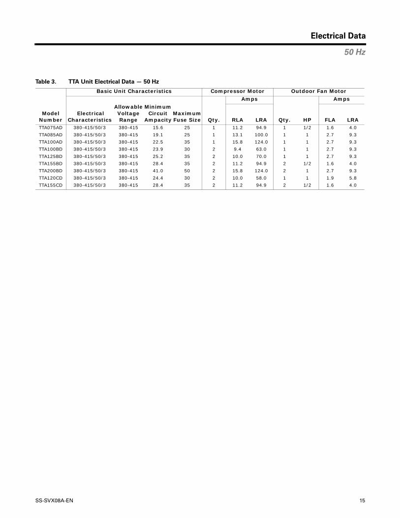
Table 3. TTA Unit Electrical Data — 50 Hz
Model Number
Basic Unit Characteristics Compressor Motor Outdoor Fan Motor
Qty.
Amps
Qty. HP
Amps
ElectricalCharacteristics
AllowableVoltageRange
Minimum Circuit
AmpacityMaximum Fuse Size RLA LRA FLA LRA
TTA075AD 380-415/50/3 380-415 15.6 25 1 11.2 94.9 1 1/2 1.6 4.0
TTA085AD 380-415/50/3 380-415 19.1 25 1 13.1 100.0 1 1 2.7 9.3
TTA100AD 380-415/50/3 380-415 22.5 35 1 15.8 124.0 1 1 2.7 9.3
TTA100BD 380-415/50/3 380-415 23.9 30 2 9.4 63.0 1 1 2.7 9.3
TTA125BD 380-415/50/3 380-415 25.2 35 2 10.0 70.0 1 1 2.7 9.3
TTA155BD 380-415/50/3 380-415 28.4 35 2 11.2 94.9 2 1/2 1.6 4.0
TTA200BD 380-415/50/3 380-415 41.0 50 2 15.8 124.0 2 1 2.7 9.3
TTA120CD 380-415/50/3 380-415 24.4 30 2 10.0 58.0 1 1 1.9 5.8
TTA155CD 380-415/50/3 380-415 28.4 35 2 11.2 94.9 2 1/2 1.6 4.0
50 Hz
16 SS-SVX08A-EN
Refrigerant Piping Guidelines
1. Maximum recommended line lengths (per circuit):
2. Maximum allowable pressure drops (R22):
Note: Route refrigerant piping for minimum linear length, minimum number of bends and fittings (no reducers) and minimum amount of line exposed to outdoor ambients.
3. Recommended line sizes TTA075, 085, 090, 100 and 120A (single circuit), TTA155B, 180, 200, 240B (dual circuit), and TTA100 and 120C (two speed):
:
4. Recommended line sizes TTA100, TTA120B, TTA125B, TTA150B (dual circuit)
5. Recommended line sizes TTA155 and 180C (two speed)
Note: Insulate all refrigerant piping and connections.
Refrigerant Piping Procedures (Outdoor Units)
Each TTA unit ships with a holding charge of dry nitrogen. The nitrogen should be removed and the entire system evacuated (at the proper time) to avoid possible contamination.
1. Remove the compressor service access panel.
2. Locate the liquid and suction line service valves. Check that the piping connection stubs on the valves (Figure 3, p. 9) line up properly with the holes in the unit cabinet.
3. Remove the refrigerant connection seal caps and open the service valve slowly to release the nitrogen from the unit.
Installation
Maximum linear length...................... 80 Ft. (w/o accumulator)
Maximum suction line lift................... 60 Ft.
Maximum liquid line lift .................... 60 Ft.
Suction Line..................................... 6 psi
Liquid Line ...................................... 35 psi (w/o subcooler)
Suction Line.......... 1 3/8" sealed type L refrigerant tubing
Liquid Line............ 1/2" sealed type L refrigerant tubing
Suction Line............... 1 1/8" sealed type L refrigerant tubing
Liquid Line................. 3/8" sealed type L refrigerant tubing
Suction Line............... 1 5/8" sealed type L refrigerant tubing
Liquid Line................. 5/8" sealed type L refrigerant tubing

SS-SVX08A-EN 17
Installation
CAUTION System Component Damage!
Do not remove the seal caps from refrigerant connections, or open the service valves
until prepared to braze refrigerant lines to the connections. Excessive exposure to
atmosphere (> 5 min.) may allow moisture or dirt to contaminate the system,
damaging valve seals and causing ice formation in system components.
4. Cut, fit and braze tubing, starting at the outdoor unit and work toward the indoor unit.
Note: Use long radius ells for all 90° bends.
All brazing should be done using a 2 to 8 psig dry nitrogen purge flowing through the pipe being brazed, Figure 9.
CAUTION System Component Damage!
Install a regulating valve between the nitrogen source and the gauge manifold
(Figure 9). Unregulated pressure can damage system components.
CAUTION System Component Damage!
Wet-wrap all valves and protect painted surfaces from excessive heat. Heat can
damage system components and the unit finish.
5. Shut off nitrogen supply. Shut off the manifold valve for the line that is connected to the suction line service valve. Disconnect the line from the gauge port on the valve.
Figure 9. Outdoor Units - Refrigerant Piping (w/ Dry Nitrogen)
18 SS-SVX08A-EN
Installation
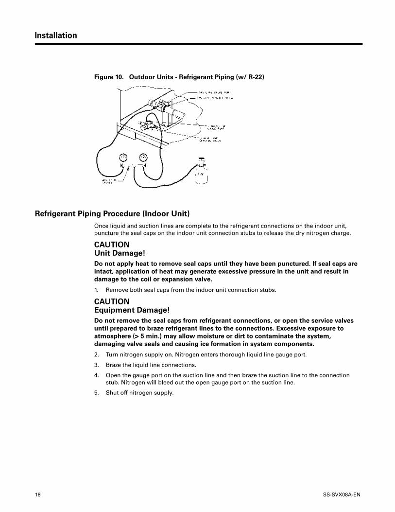
Refrigerant Piping Procedure (Indoor Unit)
Once liquid and suction lines are complete to the refrigerant connections on the indoor unit, puncture the seal caps on the indoor unit connection stubs to release the dry nitrogen charge.
CAUTION Unit Damage!
Do not apply heat to remove seal caps until they have been punctured. If seal caps are
intact, application of heat may generate excessive pressure in the unit and result in
damage to the coil or expansion valve.
1. Remove both seal caps from the indoor unit connection stubs.
CAUTION Equipment Damage!
Do not remove the seal caps from refrigerant connections, or open the service valves
until prepared to braze refrigerant lines to the connections. Excessive exposure to
atmosphere (> 5 min.) may allow moisture or dirt to contaminate the system,
damaging valve seals and causing ice formation in system components.
2. Turn nitrogen supply on. Nitrogen enters thorough liquid line gauge port.
3. Braze the liquid line connections.
4. Open the gauge port on the suction line and then braze the suction line to the connection stub. Nitrogen will bleed out the open gauge port on the suction line.
5. Shut off nitrogen supply.
Figure 10. Outdoor Units - Refrigerant Piping (w/ R-22)
SS-SVX08A-EN 19
Installation
Leak Check
After the brazing operation of refrigerant lines to both the outdoor and indoor unit is completed, the field brazed connections must be checked for leaks. Pressurize the system through the service valve with dry nitrogen to 200 psi. Use soap bubbles or other leak-checking methods to ensure that all field joints are leak free. If not, release pressure, repair and repeat leak test.
System Evacuation
1. After completion of leak check, evacuate the system.
2. Attach appropriate hoses from manifold gauge to gas and liquid line pressure taps.
Note: Unnecessary switching of hoses can be avoided and complete evacuation of all lines leading to sealed system can be accomplished with manifold center hose and connecting branch hose to a cylinder of R-22 and vacuum pump.
3. Attach center hose of manifold gauges to vacuum pump.
4. Evacuate the system to hold a 350 micron vacuum.
5. Close off valve to vacuum pump and observe the micron gauge. If gauge pressure rises above 500 microns in one (1) minute, then evacuation is incomplete or the system has a leak.
6. If vacuum gauge does not rise above 500 microns in one (1) minute, the evacuation should be complete.
7. With vacuum pump and micron gauge blanked off, open valve on R-22 cylinder and allow refrigerant pressure to build up to about 40 psig.
8. Close valve on the R-22 supply cylinder. Close valves on manifold gauge set and remove refrigerant charging hoses from liquid and gas gauge ports.
9. Leak test the entire system. Using proper procedures and caution, repair any leaks found and repeat the leak test.
Refrigerant Charging Procedure
If charging by weight, refer to refrigerant charges that are given in Table 4, p. 20. If additional refrigerant is needed because of length of line, calculate the requirement using Table 5, p. 20.
Charge by weight through the gauge port on the liquid line. Once the charge enters the system, backseat (open) the liquid line service valve and disconnect the charging line and replace the cap on the gauge port.
Insulating and Isolating Refrigerant Lines
Insulate the entire suction line with refrigerant piping insulation. Also insulate any portion of the liquid line exposed to temperature extremes. Insulate and isolate liquid and suction lines from each other. Isolate refrigerant lines from the structure and any duct work.
Note: To prevent possible noise or vibration problems, be certain to isolate refrigerant lines from the building.

20 SS-SVX08A-EN
Installation
Note: For tubing over 40 ft. calculate the additional refrigerant needed, based on note above.
Table 4. TTA Refrigerant Charge (R-22)
Model Refrigerant Charge
TTA090A16 lbs 0.0 ozs
TTA075A
TTA085A
19 lbs 0.0 ozsTTA120A
TTA100A
TTA120B10 lbs 8.0 ozs (ea. Ckt.)
TTA100B
TTA150B11 lbs13.0 ozs (ea. Ckt.)
TTA125B
TTA180B15 lbs 0.0 ozs (ea. Ckt.)
TTA155B
TTA240B18 lbs 0.0 ozs (ea. Ckt.)
TTA200B
TTA120C20 lbs 8.0 ozs
TTA100C
TTA180C28 lbs 0.0 ozs
TTA155C
Notes:
1. *Sufficient operating charge for outdoor unit and 25 feet of nominally sized refrigerant piping.
Table 5. Additional Required Refrigerant
Tubing Sizes Additional Tubing Length
Additional RefrigerantSuction Liquid
1 1/8 "3/8 "15 ft. 0 lb 11.5 oz1
25 ft. 1 lb 3.0 oz1
32 ft. 1 lb 8.0 oz1
40 ft. 1 lb 14.0 oz1
1 3/8 "1/2 "15 ft. 1 lb 4.0 oz2
25 ft. 2 lb 1.0 oz2
32 ft. 2 lb 11.0 oz2
40 ft. 3 lb 1.0 oz2
1 5/8 "5/8 "15 ft. 1 lb 15.0 oz3
25 ft. 3 lb 4.5 oz3
32 ft. 4 lb 3.2 oz3
40 ft. 5 lb 4.0 oz3
Notes:
1. Amounts shown are based on .75 ounces of refrigerant per foot of 1 1/8" and 3/8" lines.
2. Amounts shown are based on 1.33 ounces of refrigerant per foot of 1 3/8" and 1/2" lines.
3. Amounts shown are based on 2.1 ounces of refrigerant per foot of 1 5/8" and 5/8" lines.
SS-SVX08A-EN 21
Installation
Gaseous Charging
This procedure is accomplished with the unit operating. Electrical connections must be complete. Do not proceed until the system is ready to operate.
1. Connect R-22 drum with gauge manifold to the Schrader valves (pressure taps) on the compressor discharge and suction lines, Figure 10, p. 18.
Note: On the TTA075A, 090A, 100A, 100B, 100C, 120A, 120B and 120C, the compressor access panel must be installed when the unit is running and being charged. The control box access panel must be removed, and the manifold hoses must be routed through an opening located in the bottom front of the control box. The opening has a pivoted cover plate.
Note: On the TTA125B, 150B, 155B, 180B, 155C, 180C, 200B and 240B, there is a 1 1/2" diameter refrigerant gauge access hole(s) with a removable silver cap located adjacent to the refrigerant line openings.
� WARNING Live Electrical Components!
During installation, testing, servicing and troubleshooting of this product, it may be
necessary to work with live electrical components. Have a qualified licensed electrician
or other individual who has been properly trained in handling live electrical
components perform these tasks. Failure to follow all electrical safety precautions
when exposed to live electrical components could result in death or serious injury.
2. Turn on power to the unit. Allow the system to run for 5 to 10 minutes to stabilize operating conditions.
3. Measure airflow across the indoor coil. Compare the measurements with the fan performance data in the Data/Submittal or Service Facts. Once proper airflow is established, observe the suction and head pressure gauges on the gauge manifold. Pressure reading should fall approximately at the points shown by the pressure curves in Service Facts. Add or remove refrigerant (gas only) as required to obtain correct head and suction pressures. Check suction line superheat and condenser sub-cooling to ensure the unit is operating properly.
4. Disconnect all power to the unit.
� WARNING Hazardous Voltage w/Capacitors!
Disconnect all electric power, including remote disconnects and discharge all motor
start/run capacitors before servicing. Follow proper lockout/tagout procedures to
ensure the power cannot be inadvertently energized. For variable frequency drives or
other energy storing components provided by Trane or others, refer to the appropriate
manufacturer’s literature for allowable waiting periods for discharge of capacitors.
Verify with an appropriate voltmeter that all capacitors have discharged. Failure to
disconnect power and discharge capacitors before servicing could result in death or
serious injury.
5. Remove the charging system from the unit and close the opening in the bottom of the control box with the pivotal cover before attempting to replace access panel.
6. Replace all panels.
Electrical Wiring
TTA field wiring consists of providing power supply to the unit, installing the system indoor thermostat and providing low voltage system interconnecting wiring. Access to electrical connection locations are shown in Figures 2 - 8.
22 SS-SVX08A-EN
Installation
� WARNING Ground Required!
Follow proper local and state electrical code on requirements for grounding. Failure to
follow code could result in death or serious injury.
Unit Power Supply
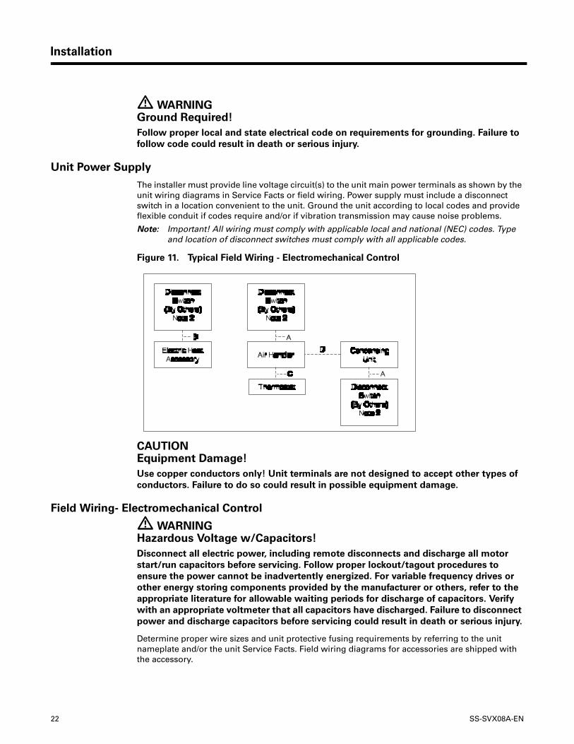
The installer must provide line voltage circuit(s) to the unit main power terminals as shown by the unit wiring diagrams in Service Facts or field wiring. Power supply must include a disconnect switch in a location convenient to the unit. Ground the unit according to local codes and provide flexible conduit if codes require and/or if vibration transmission may cause noise problems.
Note: Important! All wiring must comply with applicable local and national (NEC) codes. Type and location of disconnect switches must comply with all applicable codes.
CAUTION Equipment Damage!
Use copper conductors only! Unit terminals are not designed to accept other types of
conductors. Failure to do so could result in possible equipment damage.
Field Wiring- Electromechanical Control
� WARNING Hazardous Voltage w/Capacitors!
Disconnect all electric power, including remote disconnects and discharge all motor
start/run capacitors before servicing. Follow proper lockout/tagout procedures to
ensure the power cannot be inadvertently energized. For variable frequency drives or
other energy storing components provided by the manufacturer or others, refer to the
appropriate literature for allowable waiting periods for discharge of capacitors. Verify
with an appropriate voltmeter that all capacitors have discharged. Failure to disconnect
power and discharge capacitors before servicing could result in death or serious injury.
Determine proper wire sizes and unit protective fusing requirements by referring to the unit nameplate and/or the unit Service Facts. Field wiring diagrams for accessories are shipped with the accessory.
Figure 11. Typical Field Wiring - Electromechanical Control
SS-SVX08A-EN 23
Installation
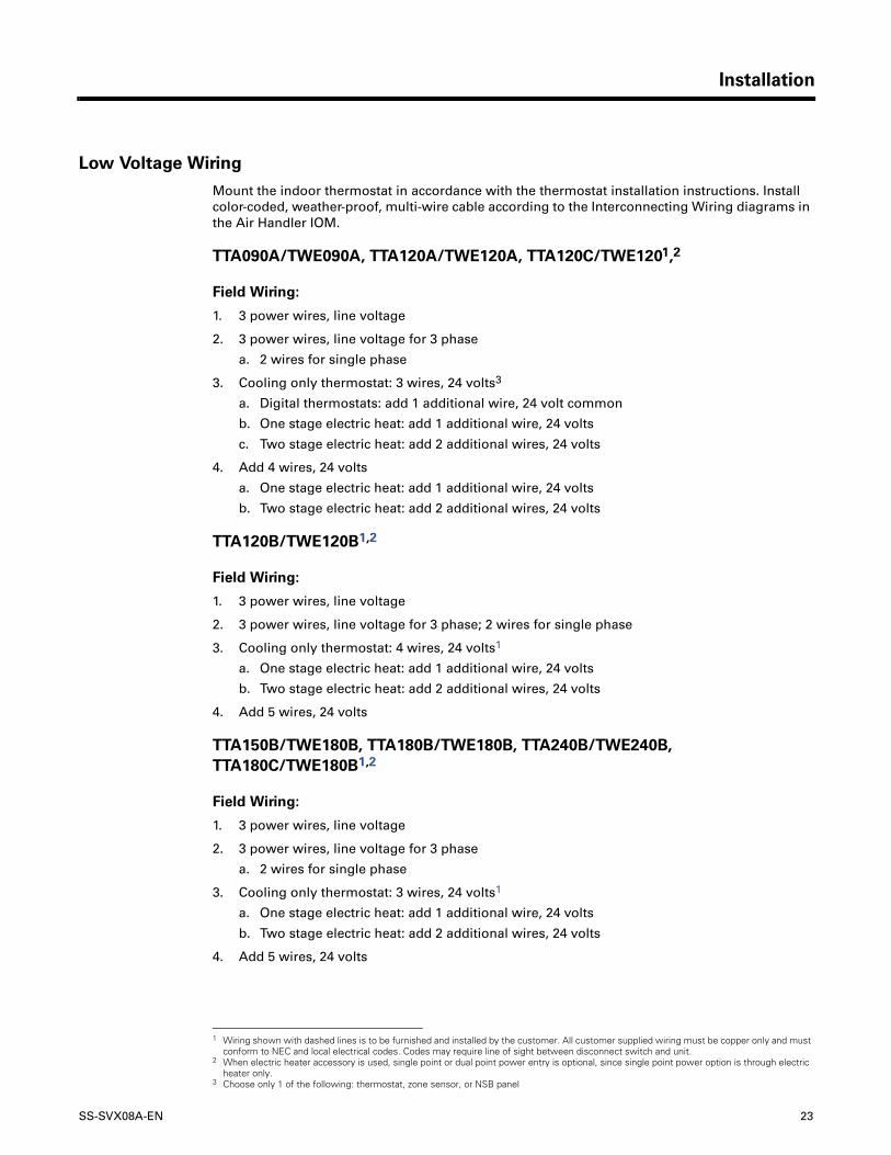
Low Voltage Wiring
Mount the indoor thermostat in accordance with the thermostat installation instructions. Install color-coded, weather-proof, multi-wire cable according to the Interconnecting Wiring diagrams in the Air Handler IOM.
TTA090A/TWE090A, TTA120A/TWE120A, TTA120C/TWE1201,2
Field Wiring:
1. 3 power wires, line voltage
2. 3 power wires, line voltage for 3 phase
a. 2 wires for single phase
3. Cooling only thermostat: 3 wires, 24 volts3
a. Digital thermostats: add 1 additional wire, 24 volt common
b. One stage electric heat: add 1 additional wire, 24 volts
c. Two stage electric heat: add 2 additional wires, 24 volts
4. Add 4 wires, 24 volts
a. One stage electric heat: add 1 additional wire, 24 volts
b. Two stage electric heat: add 2 additional wires, 24 volts
TTA120B/TWE120B1,2
Field Wiring:
1. 3 power wires, line voltage
2. 3 power wires, line voltage for 3 phase; 2 wires for single phase
3. Cooling only thermostat: 4 wires, 24 volts1
a. One stage electric heat: add 1 additional wire, 24 volts
b. Two stage electric heat: add 2 additional wires, 24 volts
4. Add 5 wires, 24 volts
TTA150B/TWE180B, TTA180B/TWE180B, TTA240B/TWE240B, TTA180C/TWE180B1,2
Field Wiring:
1. 3 power wires, line voltage
2. 3 power wires, line voltage for 3 phase
a. 2 wires for single phase
3. Cooling only thermostat: 3 wires, 24 volts1
a. One stage electric heat: add 1 additional wire, 24 volts
b. Two stage electric heat: add 2 additional wires, 24 volts
4. Add 5 wires, 24 volts
1 Wiring shown with dashed lines is to be furnished and installed by the customer. All customer supplied wiring must be copper only and must conform to NEC and local electrical codes. Codes may require line of sight between disconnect switch and unit.
2 When electric heater accessory is used, single point or dual point power entry is optional, since single point power option is through electric heater only.
3 Choose only 1 of the following: thermostat, zone sensor, or NSB panel
24 SS-SVX08A-EN
Installation
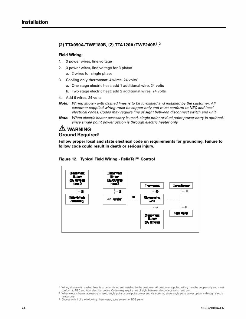
(2) TTA090A/TWE180B, (2) TTA120A/TWE240B1,2
Field Wiring:
1. 3 power wires, line voltage
2. 3 power wires, line voltage for 3 phase
a. 2 wires for single phase
3. Cooling only thermostat: 4 wires, 24 volts3
a. One stage electric heat: add 1 additional wire, 24 volts
b. Two stage electric heat: add 2 additional wires, 24 volts
4. Add 6 wires, 24 volts
Note: Wiring shown with dashed lines is to be furnished and installed by the customer. All customer supplied wiring must be copper only and must conform to NEC and local electrical codes. Codes may require line of sight between disconnect switch and unit.
Note: When electric heater accessory is used, single point or dual point power entry is optional, since single point power option is through electric heater only.
� WARNING Ground Required!
Follow proper local and state electrical code on requirements for grounding. Failure to
follow code could result in death or serious injury.
1 Wiring shown with dashed lines is to be furnished and installed by the customer. All customer supplied wiring must be copper only and must conform to NEC and local electrical codes. Codes may require line of sight between disconnect switch and unit.
2 When electric heater accessory is used, single point or dual point power entry is optional, since single point power option is through electric heater only.
3 Choose only 1 of the following: thermostat, zone sensor, or NSB panel
Figure 12. Typical Field Wiring - ReliaTel™ Control
SS-SVX08A-EN 25
Installation
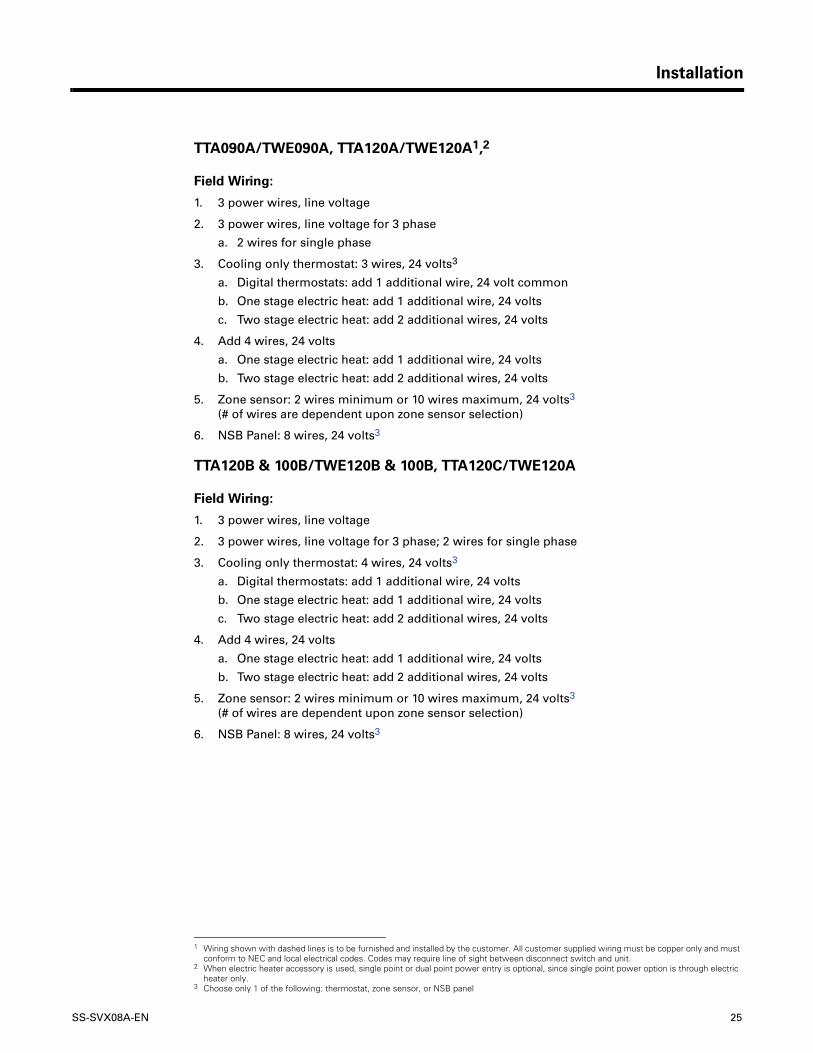
TTA090A/TWE090A, TTA120A/TWE120A1,2
Field Wiring:
1. 3 power wires, line voltage
2. 3 power wires, line voltage for 3 phase
a. 2 wires for single phase
3. Cooling only thermostat: 3 wires, 24 volts3
a. Digital thermostats: add 1 additional wire, 24 volt common
b. One stage electric heat: add 1 additional wire, 24 volts
c. Two stage electric heat: add 2 additional wires, 24 volts
4. Add 4 wires, 24 volts
a. One stage electric heat: add 1 additional wire, 24 volts
b. Two stage electric heat: add 2 additional wires, 24 volts
5. Zone sensor: 2 wires minimum or 10 wires maximum, 24 volts3 (# of wires are dependent upon zone sensor selection)
6. NSB Panel: 8 wires, 24 volts3
TTA120B & 100B/TWE120B & 100B, TTA120C/TWE120A
Field Wiring:
1. 3 power wires, line voltage
2. 3 power wires, line voltage for 3 phase; 2 wires for single phase
3. Cooling only thermostat: 4 wires, 24 volts3
a. Digital thermostats: add 1 additional wire, 24 volts
b. One stage electric heat: add 1 additional wire, 24 volts
c. Two stage electric heat: add 2 additional wires, 24 volts
4. Add 4 wires, 24 volts
a. One stage electric heat: add 1 additional wire, 24 volts
b. Two stage electric heat: add 2 additional wires, 24 volts
5. Zone sensor: 2 wires minimum or 10 wires maximum, 24 volts3 (# of wires are dependent upon zone sensor selection)
6. NSB Panel: 8 wires, 24 volts3
1 Wiring shown with dashed lines is to be furnished and installed by the customer. All customer supplied wiring must be copper only and must conform to NEC and local electrical codes. Codes may require line of sight between disconnect switch and unit.
2 When electric heater accessory is used, single point or dual point power entry is optional, since single point power option is through electric heater only.
3 Choose only 1 of the following: thermostat, zone sensor, or NSB panel
26 SS-SVX08A-EN
Installation
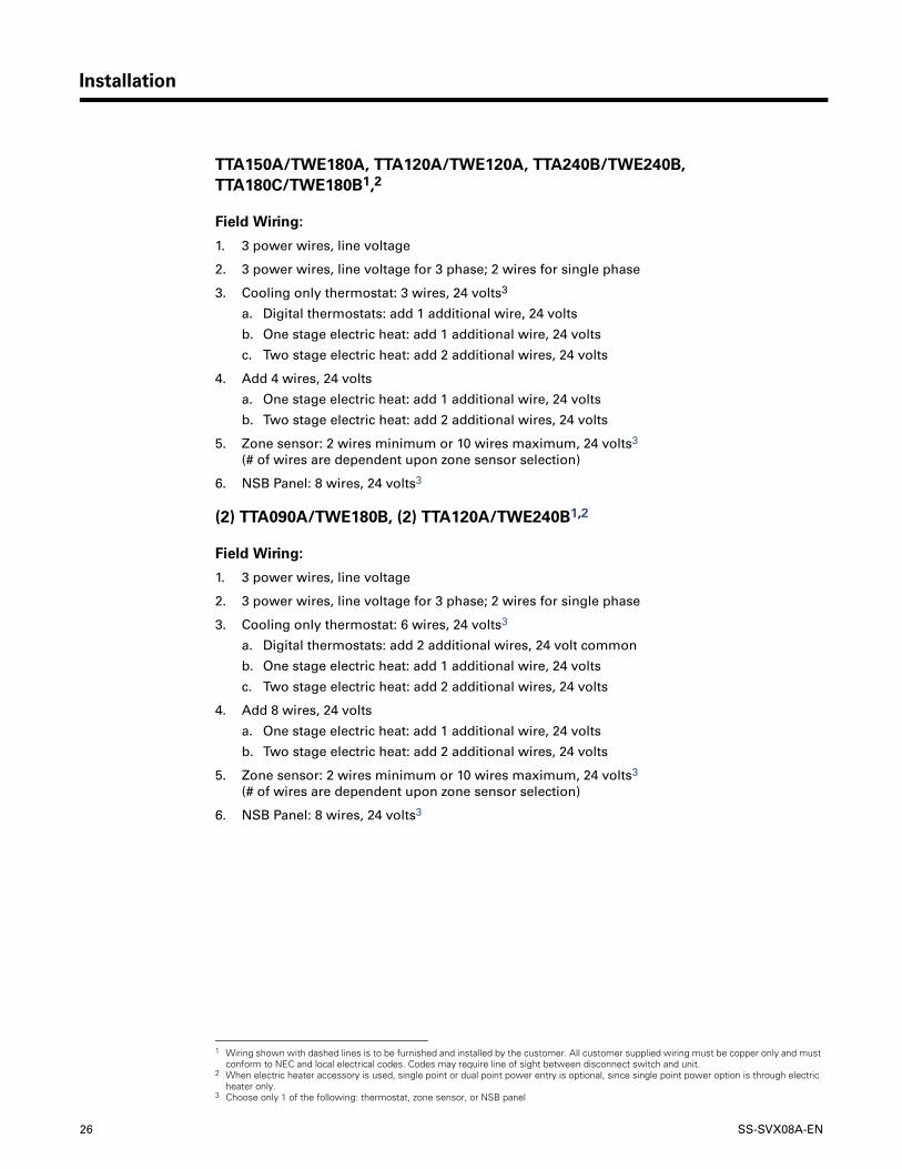
TTA150A/TWE180A, TTA120A/TWE120A, TTA240B/TWE240B, TTA180C/TWE180B1,2
Field Wiring:
1. 3 power wires, line voltage
2. 3 power wires, line voltage for 3 phase; 2 wires for single phase
3. Cooling only thermostat: 3 wires, 24 volts3
a. Digital thermostats: add 1 additional wire, 24 volts
b. One stage electric heat: add 1 additional wire, 24 volts
c. Two stage electric heat: add 2 additional wires, 24 volts
4. Add 4 wires, 24 volts
a. One stage electric heat: add 1 additional wire, 24 volts
b. Two stage electric heat: add 2 additional wires, 24 volts
5. Zone sensor: 2 wires minimum or 10 wires maximum, 24 volts3 (# of wires are dependent upon zone sensor selection)
6. NSB Panel: 8 wires, 24 volts3
(2) TTA090A/TWE180B, (2) TTA120A/TWE240B1,2
Field Wiring:
1. 3 power wires, line voltage
2. 3 power wires, line voltage for 3 phase; 2 wires for single phase
3. Cooling only thermostat: 6 wires, 24 volts3
a. Digital thermostats: add 2 additional wires, 24 volt common
b. One stage electric heat: add 1 additional wire, 24 volts
c. Two stage electric heat: add 2 additional wires, 24 volts
4. Add 8 wires, 24 volts
a. One stage electric heat: add 1 additional wire, 24 volts
b. Two stage electric heat: add 2 additional wires, 24 volts
5. Zone sensor: 2 wires minimum or 10 wires maximum, 24 volts3 (# of wires are dependent upon zone sensor selection)
6. NSB Panel: 8 wires, 24 volts3
1 Wiring shown with dashed lines is to be furnished and installed by the customer. All customer supplied wiring must be copper only and must conform to NEC and local electrical codes. Codes may require line of sight between disconnect switch and unit.
2 When electric heater accessory is used, single point or dual point power entry is optional, since single point power option is through electric heater only.
3 Choose only 1 of the following: thermostat, zone sensor, or NSB panel
SS-SVX08A-EN 27
Wiring Diagram
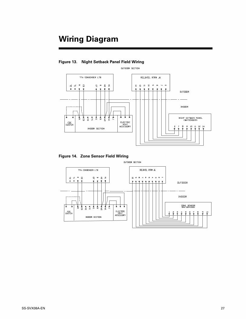
Figure 13. Night Setback Panel Field Wiring
Figure 14. Zone Sensor Field Wiring
28 SS-SVX08A-EN
Wiring Diagram
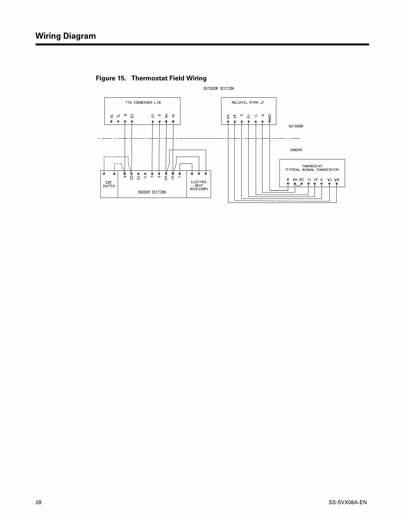
Figure 15. Thermostat Field Wiring
SS-SVX08A-EN 29
Refrigerant Circuit
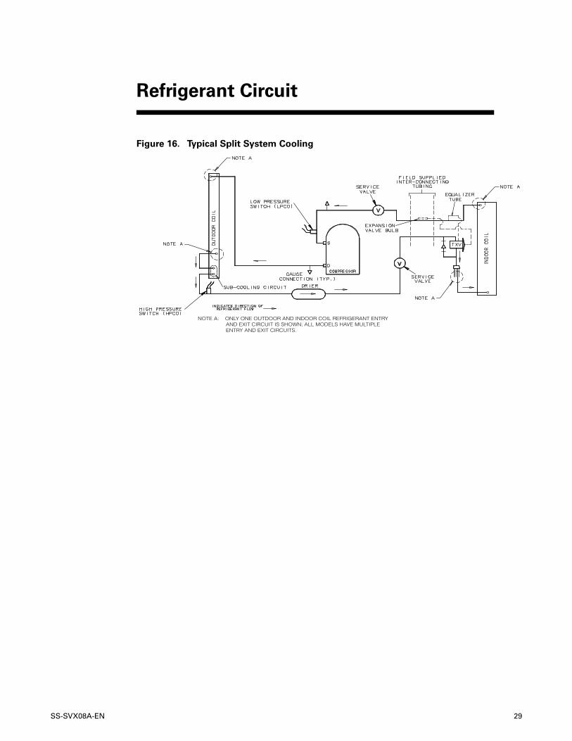
Figure 16. Typical Split System Cooling
NOTE A: ONLY ONE OUTDOOR AND INDOOR COIL REFRIGERANT ENTRY AND EXIT CIRCUIT IS SHOWN; ALL MODELS HAVE MULTIPLE ENTRY AND EXIT CIRCUITS.
30 SS-SVX08A-EN
Safety Controls
Note: All of these controls may not be installed on your unit, check electrical schematic.
Low Outdoor Ambient Cooling
The Evaporator Defrost Control is standard equipment on Air Handlers and will permit low ambient cooling down to 35°F. For cooling operation down to 0°F, use an Accessory Head Pressure Control on the outdoor unit.
Evaporator Defrost Control (EDC)
This control is located in the Air Handler of Split Units. The control’s sensing tube is embedded vertically in the evaporator coil, near the center. This device will stop the compressor if the indoor coil temperature drops below its setting. The indoor air will still circulate across the coil bringing the temperature of the coil back up to the cut-in temperature of the evaporator defrost control.
Low Pressure Cut-Out (LPCO)
This control’s sensor is located in the suction (gas) line, near the compressor. This control will stop the compressor and the outdoor fans if suction pressure drops below the Low Pressure Cut-Out setting. Once the suction pressure has returned to normal, the compressor and outdoor fans will cycle back on.
High Pressure Cut-Out (HPCO)
This control’s sensor is located in the discharge line. This device will shut off the compressor and the outdoor fan(s) if the discharge pressure exceeds the High Pressure Cut-Out’s setting. Once the discharge pressure has returned to normal, the compressor will cycle back on.
Internal Overload Protector (IOL)
This device is a current/thermal actuated warp switch, embedded in the compressor motor windings. It will shut off the compressor if the discharge temperature or current of the compressor windings exceeds its design trip temperature.
Note: The IOL will put the compressor back in operation once the compressor motor heat has dropped below the trip setting; however, a check of the refrigerant and electrical systems should be made to determine the cause and be corrected.
Installation Checklist
Complete this checklist once the unit is installed to verify that all recommended procedures have been accomplished before starting the system. Do not operate the system until all items covered by this checklist are complete.
1. Inspect unit location for proper required service clearances.
2. Inspect unit location for proper free air clearances.
3. Inspect unit location for secure, level mounting position.
Pre-Start
SS-SVX08A-EN 31
Pre-Start
Refrigerant Piping
1. Performed initial leak test?
2. Connected properly sized and constructed liquid and suction lines to the connection stubs at both the indoor and outdoor units?
3. Insulated the entire suction line?
4. Insulated portions of liquid line exposed to extremes in temperature?
5. Evacuated each refrigerant circuit to 350 microns?
6. Charged each circuit with proper amount of R-22?
Electrical Wiring
1. Provided unit power wiring (with disconnect) to proper terminals in the unit control section?
2. Installed system indoor thermostat?
3. Installed system low voltage interconnecting wiring to proper terminals of outdoor unit, indoor unit and system thermostat?
32 SS-SVX08A-EN
Electromechanical Controls
Unit Model Number Digits 9 and 10 = 00 or 0S
Sequence of Operation
Once the unit is properly installed and pre-start procedures are complete, start the unit by turning the System Switch on the indoor thermostat to either HEAT, COOL or AUTO. The system should operate normally.
CAUTION Equipment Damage!
Ensure the disconnect for the indoor air handler is closed before operating the system.
Operating the indoor unit without the indoor fan energized can cause unit trip-out on
high pressure control and/or liquid flood back to the compressor.
General
Operation of the system cooling (and optional heating) cycles is controlled by the position of the system switch on the room thermostat. Once the system switch is placed in either the HEAT or COOL position, unit operation is automatic. The optional automatic changeover thermostat, when in the AUTO position, automatically changes to heat or cool with sufficient room temperature change.
Evaporator Fan (Indoor Supply Air)
The evaporator fan is controlled by an ON/AUTO switch on the room thermostat. With the switch positioned at AUTO and the system operating in the cooling mode, fan operation coincides with the cooling run cycles. If the system is equipped with heat and is operating in the heating mode while the fan switch is at AUTO, fan operation coincides with the heating run cycles. When the fan switch is positioned at ON, fan operation is continuous.
Cooling Mode
With the disconnect switch in the ON position, current is supplied to the compressor sump heater(s) and control transformer. The sump heater(s) supplies heat to the compressor(s) during the “Off” cycle. The transformer steps down the line voltage to 24V for the low voltage control circuit. When the room thermostat system switch is positioned at COOL and the fan switch is at AUTO, the compressor contactor energizes on a call for cooling.
When the contacts of the compressor contactor close, operation of the compressor and condenser fan begins. The evaporator fan contactor also energizes on a call for cooling and initiates evaporator fan operation.
On units with dual circuits, the second stage of cooling is initiated as a result of the 2-stage thermostat calling for additional cooling.
Start-Up
SS-SVX08A-EN 33
Start-Up
ReliaTel™ Control
Unit Model Number Digits 9 and 10 = 0R, 0T, OU or OW
Sequence of Operation
Once the unit is properly installed and pre-start procedures are complete, start the unit by turning the System Switch on the indoor thermostat to either HEAT, COOL or AUTO. The system should operate normally.
CAUTION Equipment Damage!
Ensure the disconnect for the indoor air handler is closed before operating the system.
Operating the indoor unit without the indoor fan energized can cause unit trip-out on
high pressure control and/or liquid flood back to the compressor.
The ReliaTel™ Controls is a microelectronic control feature, which provides operating functions that are significantly different than conventional Electromechanical units. The ReliaTel™ Refrigeration Module (RTRM) uses Proportional/Integral control algorithms to perform specific unit functions that govern the unit operation in response to application conditions.
The RTRM provides compressor anti-short cycle timing functions through minimum “Off” and “On” timing to increase reliability, performance and to maximize unit efficiency. Upon power initialization, the RTRM performs self-diagnostic checks to ensure that all internal controls are functioning. It checks the configuration parameters against the components connected to the system. The Light Port LED located on the RTRM module is turned “On” within one second after power-up if all internal operations are okay.
ReliaTel™ Control Cooling Mode
For Zone Sensor Control:
When the system switch is set to the COOL position and the zone temperature rises above the cooling setpoint, the RTRM energizes the compressor relay coil located on the RTRM. When the compressor relay contacts close, the compressor contactor coil is energized provided the low and high pressure controls are closed. When the compressor contacts close, the compressor and the outdoor fan motor start to maintain the zone temperature to within ± 2°F of the sensor setpoint at the sensed location.
On units with dual circuits, the second stage of cooling is initiated as a result of the Proportional/Integral control algorithms calling for additional cooling.
For Thermostat Control:
When the room thermostat system switch is positioned at COOL and the fan switch is at AUTO, the RTRM energizes the compressor relay coil located on the RTRM during a call for cooling. When the compressor relay contacts close, the compressor contactor coil is energized provided the low and high pressure controls are closed.
When the contacts of the compressor contactor close, operation of the compressor and condenser fan begins. The evaporator fan contactor also energizes on a call for cooling and initiates evaporator fan operation.
On units with dual circuits, the second stage of cooling is initiated as a result of the 2-stage thermostat calling for additional cooling.
34 SS-SVX08A-EN
Start-Up
Note: Irregular unit operation may occur when the unit is controlled with a triac-switching thermostat. Please review the approved thermostat vendor list for all recommended relay-switching thermostats.
ReliaTel™ Control Evaporator Fan Operation
When the fan selection switch is set to the AUTO position, the RTRM energizes the evaporator fan relay coil approximately 1 second after energizing the compressor contactor coil in the cooling mode. In the heating mode, the RTRM energizes the evaporator fan relay coil approximately 1 second before energizing the electric heat contactors. In cooling mode, when the cooling cycle is terminated, the RTRM will allow the evaporator fan relay coil to remain energized for 80 seconds on single compressor units and 60 seconds on multiple compressor units to extract “free” cooling from the indoor coil. When the heating cycle is terminated, the evaporator fan relay coil is de-energized at the same time as the heater contactors. When the fan selection switch is set to the ON position, the RTRM keeps the evaporator fan relay coil energized for continuous fan motor operation.
ReliaTel™ Control Heating Operation
When the system switch is set to the HEAT position and heating is required, the RTRM energizes the Heat 1 relay coil. When the Heat 1 relay contacts close, the first stage electric heat contactor is energized. If the first stage of electric heat cannot satisfy the heating requirement, the RTRM energizes the Heat 2 relay coil. When the Heat 2 relay contacts close, the second stage electric heat contactor is energized. The first and second stages of heat are cycled “On” and “Off” as required to maintain the zone.
SS-SVX08A-EN 35
Test Modes
Upon power initialization, the RTRM performs self-diagnostic checks to ensure that all internal controls are functional. It also checks the configuration parameters against the components connected to the system. The Liteport LED located on the RTRM module is turned “On” within one second of power-up if internal operation is okay.
Use one of the following “Test” procedures to bypass some time delays and to start the unit at the control panel. Each step of unit operation can be activated individually by temporarily shorting across the “Test” terminals for 2 to 3 seconds. The Liteport LED located on the RTRM module will blink when the test mode has been initiated. The unit can be left in any “Test” step for up to one hour before it will automatically terminate, or it can be terminated by opening the main power disconnect switch. Once the test mode has been terminated, the Liteport LED will glow continuously and the unit will revert to the “System” control. There are three methods in which the “Service Test” can be cycled at LTB-Test 1(T1) and LTB-Test 2 (T2).
1. Step Test Mode
This method initiates the different components of the unit, one at a time, by temporarily shorting across the two test terminals for 2 to 3 seconds.
For the initial start-up of the unit, this method allows the technician to cycle a component “On” and have up to one hour to complete the check. Service Test Mode will be ignored if a short is present across Test 1 and Test 2 at start-up.
2. Resistance Test Mode
This method can be used for start-up providing a decade box for variable resistance outputs is available. This method initiates the different components of the unit, one at a time, when a specific resistance value is placed across the two test terminals. The unit will remain in the specific test mode for approximately one hour even though the resistance is left on the test terminals.
3. Auto Test Mode
This method is not recommended for start-up due to the short timing between individual component steps. This method initiates the different components of the unit, one at a time, when a fixed jumper is installed across the test terminals. The unit will start the first test step and change to the next step every 30 seconds. At the end of the test mode, control of the unit will automatically revert to the applied “System” control method. For unit test steps, test modes and step resistance values to cycle the various components, refer to Table 6.
Service Test Modes ReliaTel™ Controls
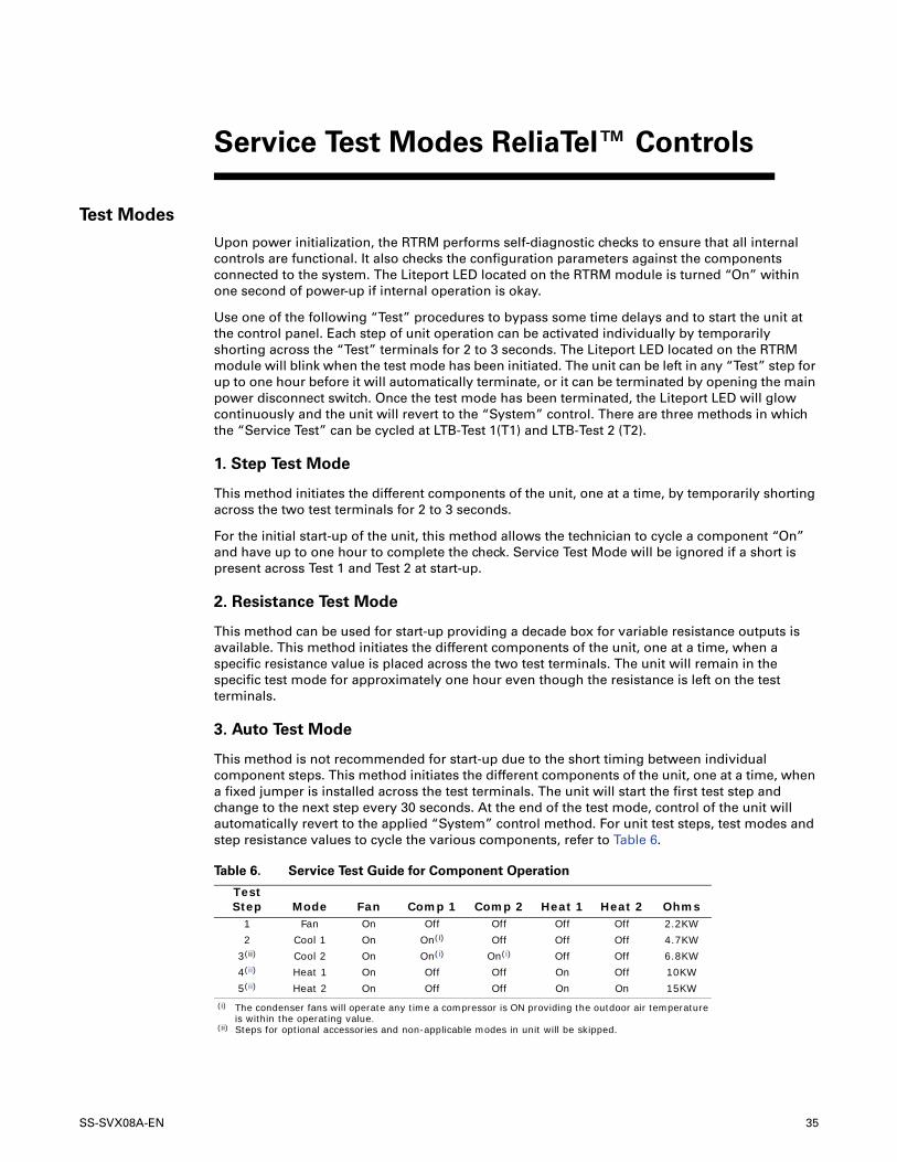
Table 6. Service Test Guide for Component Operation
Test Step Mode Fan Comp 1 Comp 2 Heat 1 Heat 2 Ohms
1 Fan On Off Off Off Off 2.2KW
2 Cool 1 On On(i)
(i) The condenser fans will operate any time a compressor is ON providing the outdoor air temperature is within the operating value.
Off Off Off 4.7KW
3(ii)
(ii) Steps for optional accessories and non-applicable modes in unit will be skipped.
Cool 2 On On(i) On(i) Off Off 6.8KW
4(ii) Heat 1 On Off Off On Off 10KW
5(ii) Heat 2 On Off Off On On 15KW
36 SS-SVX08A-EN
Trouble Shooting ReliaTel™ Controls
The RTRM has the ability to provide the service personnel with some unit diagnostics and system status information. Before turning the main power disconnect switch “Off,” follow the steps below to check the ReliaTel™ Refrigeration Module (RTRM). All diagnostics & system status information stored in the RTRM will be lost when the main power is turned “Off”.
� WARNING Hazardous Voltage w/Capacitors!
Disconnect all electric power, including remote disconnects before servicing. Follow
proper lockout/tagout procedures to ensure the power cannot be inadvertently
energized. For variable frequency drives or other energy storing components provided
by Trane or others, refer to the appropriate manufacturer’s literature for allowable
waiting periods for discharge of capacitors. Verify with an appropriate voltmeter that
all capacitors have discharged. Failure to disconnect power and discharge capacitors
before servicing could result in death or serious injury.To prevent injury or death from
electrocution, it is the responsibility of the technician to recognize this hazard and use
extreme care when performing service procedures with the electrical power energized.
� WARNING Live Electrical Components!
During installation, testing, servicing and troubleshooting of this product, it may be
necessary to work with live electrical components. Have a qualified licensed electrician
or other individual who has been properly trained in handling live electrical
components perform these tasks. Failure to follow all electrical safety precautions
when exposed to live electrical components could result in death or serious injury.
Note: The J6 & J7 screw terminals must be tightened in order to accurately measure voltage in the required steps.
1. Verify that the Liteport LED on the RTRM is burning continuously. If the LED is lit, go to Step 3.
2. If the LED is not lit, verify that 24 VAC is present between J1-1 and J1-2. If 24 VAC is present, proceed to Step 3. If 24 VAC is not present, check the unit main power supply, check transformer (TNS1). Proceed to Step 3 if necessary.
3. Utilizing “Method 1” or “Method 2” in the “System Status Diagnostic” section, check the following:
a. System status
b. Heating status
c. Cooling status
4. If a System failure is indicated, proceed to Step 4. If no failures are indicated, proceed to Step 5. If a System failure is indicated, recheck Step 1 and Step 2. If the LED is not lit in Step 1, and 24 VAC is present in Step 2, then the RTRM has failed. Replace the RTRM.
5. If no failures are indicated, use one of the TEST mode procedures described in the “Unit Start-Up” section to start the unit. This procedure will allow you to check all of the RTRM outputs, and all of the external controls (relays, contactors, etc.) that the RTRM outputs energize, for each respective mode. Proceed to Step 6.
Troubleshooting
SS-SVX08A-EN 37
Troubleshooting
6. Step the system through all of the available modes, and verify operation of all outputs, controls and modes. If a problem in operation is noted in any mode, you may leave the system in that mode for up to one hour while troubleshooting. Refer to the sequence of operations for each mode, to assist in verifying proper operation. Make the necessary repairs and proceed to Step 7 and Step 8.
7. If no abnormal operating conditions appear in the test mode, exit the test mode by turning the power”"Off” at the main power disconnect switch.
8. Refer to the individual component test procedures if other microelectronic components are suspect.
System Status Checkout Procedure
“System Status” is checked by using one of the following two methods:
Method 1. If the Zone Sensor Module (ZSM) is equipped with a remote panel with LED status indication, you can check the unit within the space. If the ZSM does not have LED’s, use Method 2. BAYSENS010B, BAYSENS011B, BAYSENS019A, BAYSENS020A, BAYSENS021A & BAYSENS023A all have the remote panel indication feature. The LED descriptions are listed below.
LED 1 (System)
• “On” during normal operation.• “Off” if a system failure occurs or the LED fails.• “Flashing” indicates test mode.
LED 2 (Heat)
• “On” when the heat cycle is operating.• “Off” when the heat cycle terminates or the LED fails.• “Flashing” indicates a heating failure.
LED 3 (Cool)
• “On” when the cooling cycle is operating.• “Off” when the cooling cycle terminates or the LED fails.• “Flashing” indicates a cooling failure.
The following information describes the complete listing of failure indication causes.
System Failure
Check the voltage between terminals 6 and 9 on J6, it should read approximately 32 VDC. If no voltage is present, a System failure has occurred. Refer to Step 4 in the previous section for the recommended troubleshooting procedure.
Cooling Failure
1. Cooling and heating set point (slide pot) on the zone sensor has failed. Refer to the "Zone Sensor Test Procedure" section.
2. Zone temperature thermistor ZTEMP on ZTS failed. Refer to the "Zone Sensor Test Procedure" section.
3. CC1 or CC2 24 VAC control circuit has opened, check CC1 & CC2 coils, and any of the controls below that apply to the unit (HPC1, HPC2).
4. LPC1 has opened during the 3 minute minimum "on time" during 4 consecutive compressor starts, check LPC1 or LPC2 by testing voltage between the J1-8 & J3-2 terminals on the RTRM and ground. If 24 VAC is present, the LPCs have not tripped. If no voltage is present, LPCs have tripped.
38 SS-SVX08A-EN
Troubleshooting
Simultaneous Heat and Cool Failure
1. Emergency Stop is activated.
Method 2. The second method for determining system status is done by checking voltage readings at the RTRM (J6). The system indication descriptions and the approximate voltages are listed below.
System Failure
Measure the voltage between terminals J6-9 & J6-6. • Normal Operation = approximately 32 VDC• System Failure = less than 1 VDC, approximately 0.75 VDC• Test Mode = voltage alternates between 32 VDC & 0.75 VDC
� WARNING Live Electrical Components!
During installation, testing, servicing and troubleshooting of this product, it may be
necessary to work with live electrical components. Have a qualified licensed electrician
or other individual who has been properly trained in handling live electrical
components perform these tasks. Failure to follow all electrical safety precautions
when exposed to live electrical components could result in death or serious injury.
Heat Failure
Measure the voltage between terminals J6-7 & J6-6.• Heat Operating = approximately 32 VDC• Heat Off = less than 1 VDC, approximately 0.75 VDC• Heating Failure = voltage alternates between 32 VDC & 0.75 VDC
Cool Failure
Measure the voltage between terminals J6-8 & J6-6.• Cool Operating = approximately 32 VDC• Cool Off = less than 1 VDC, approximately 0.75 VDC• Cooling Failure = voltage alternates between 32 VDC & 0.75 VDC
To use LED’s for quick status information at the unit, purchase a BAYSENS010* ZSM and connect wires with alligator clamps to terminals 6 through 10. Connect each respective terminal wire (6 through 10) from the Zone Sensor to the unit J6 terminals 6 through 10.
Note: If the system is equipped with a programmable zone sensor, (BAYSENS019*, or BAYSENS023*), the LED indicators will not function while the BAYSENS010* is connected.
SS-SVX08A-EN 39
Troubleshooting
Resetting Cooling and Heating Lockouts
Cooling Failures and Heating Lockouts are reset in an identical manner. Method 1 explains resetting the system from the space; Method 2 explains resetting the system at the unit.
Note: Before resetting Cooling Failures and Heating Lockouts check the Failure Status Diagnostics by the methods previously explained. Diagnostics will be lost when the power to the unit is disconnected.
Method 1. To reset the system from the space, turn the MODE selection switch at the zone sensor to the OFF position. After approximately 30 seconds, turn the MODE selection switch to the desired mode, i.e. HEAT, COOL or AUTO.
Method 2. To reset the system at the unit, cycle the unit power by turning the disconnect switch “Off” and then “On.”
Lockouts can be cleared through the building management system. Refer to the building management system instructions for more information.
Zone Temperature Sensor (ZTS) Service Indicator
The ZSM SERVICE LED is a generic indicator that will signal the closing of a Normally Open switch at any time, providing the Indoor Motor (IDM) is operating. This indicator is usually used to indicate an airside fan failure. The RTRM will ignore the closing of this Normally Open switch for 2 (±1) minutes. This helps prevent nuisance SERVICE LED indications.
Temperature Tests
Note: These procedures are not for programmable or digital models and are conducted with the Zone Sensor Module electrically removed from the system.
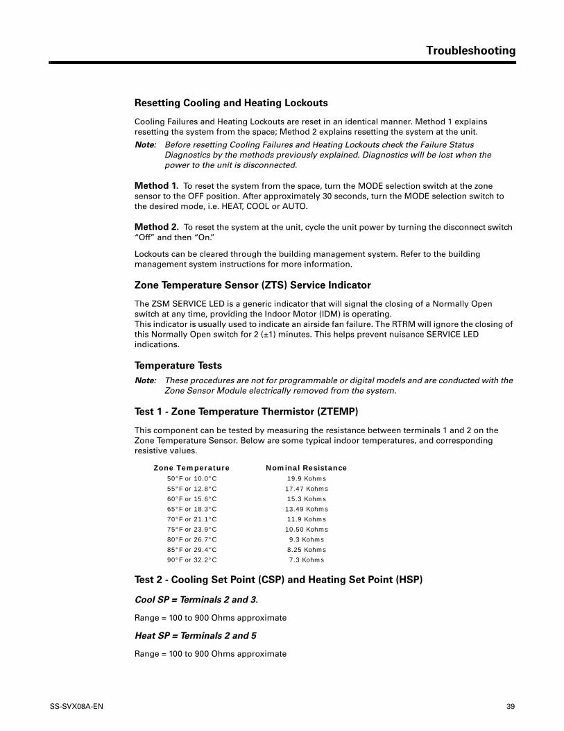
Test 1 - Zone Temperature Thermistor (ZTEMP)
This component can be tested by measuring the resistance between terminals 1 and 2 on the Zone Temperature Sensor. Below are some typical indoor temperatures, and corresponding resistive values.
Test 2 - Cooling Set Point (CSP) and Heating Set Point (HSP)
Cool SP = Terminals 2 and 3.
Range = 100 to 900 Ohms approximate
Heat SP = Terminals 2 and 5
Range = 100 to 900 Ohms approximate
Zone Temperature Nominal Resistance50°F or 10.0°C 19.9 Kohms
55°F or 12.8°C 17.47 Kohms
60°F or 15.6°C 15.3 Kohms
65°F or 18.3°C 13.49 Kohms
70°F or 21.1°C 11.9 Kohms
75°F or 23.9°C 10.50 Kohms
80°F or 26.7°C 9.3 Kohms
85°F or 29.4°C 8.25 Kohms
90°F or 32.2°C 7.3 Kohms

40 SS-SVX08A-EN
Troubleshooting
Test 3 - System Mode and Fan Selection
The combined resistance of the Mode selection switch and the Fan selection switch can be measured between terminals 2 and 4 on the Zone Sensor. The possible switch combinations are listed in Table 7 with their corresponding resistance values.
Test 4 - LED Indicator Test, (SYS ON, HEAT & COOL)
Method 1. Testing the LED using a meter with diode test function. Test both forward and reverse bias. Forward bias should measure a voltage drop of 1.5 to 2.5 volts, depending on your meter. Reverse bias will show an Over Load, or open circuit indication if LED is functional.
Method 2. Testing the LED with an analog Ohmmeter. Connect Ohmmeter across LED in one direction, then reverse the leads for the opposite direction. The LED should have at least 100 times more resistance in reverse direction, as compared with the forward direction. If high resistance in both directions, LED is open. If low in both directions, LED is shorted.
Method 3. To test LED’s with ZSM connected to unit, test voltages at LED terminals on ZSM. A measurement of 32 VDC, across an unlit LED, means the LED has failed.
Note: Measurements should be made from LED common (ZSM terminal 6 to respective LED terminal). Refer to the Zone Sensor Module (ZSM) Terminal Identification table at the beginning of this section.
Table 7. Test 3 — System Mode and Fan Selection
Resistance Valves (Ohms)
Zone Sensor Unit/Fan Mode Local Unit Mode Local Fan Mode
2.32K Off/Auto Off Auto
4.87K Cool/Auto Cool Auto
7.68K Auto/Auto Auto Auto
10.77K Off/On Off On
13.32K Cool/On Cool On
16.13K Auto/On Auto On
19.48K Heat/Auto Heat Auto
27.93K Heat/On Heat On
35.0K Emergency Heat/Auto Emergency Heat Auto
43.45K Emergency Heat/On Emergency Heat On
Out of Range (Short) INVALID/Short Invalid (CV), Auto (VAV) Invalid
Out of Range (Open) INVALID/Open Invalid (CV), Off (VAV) Invalid
SS-SVX08A-EN 41
Troubleshooting
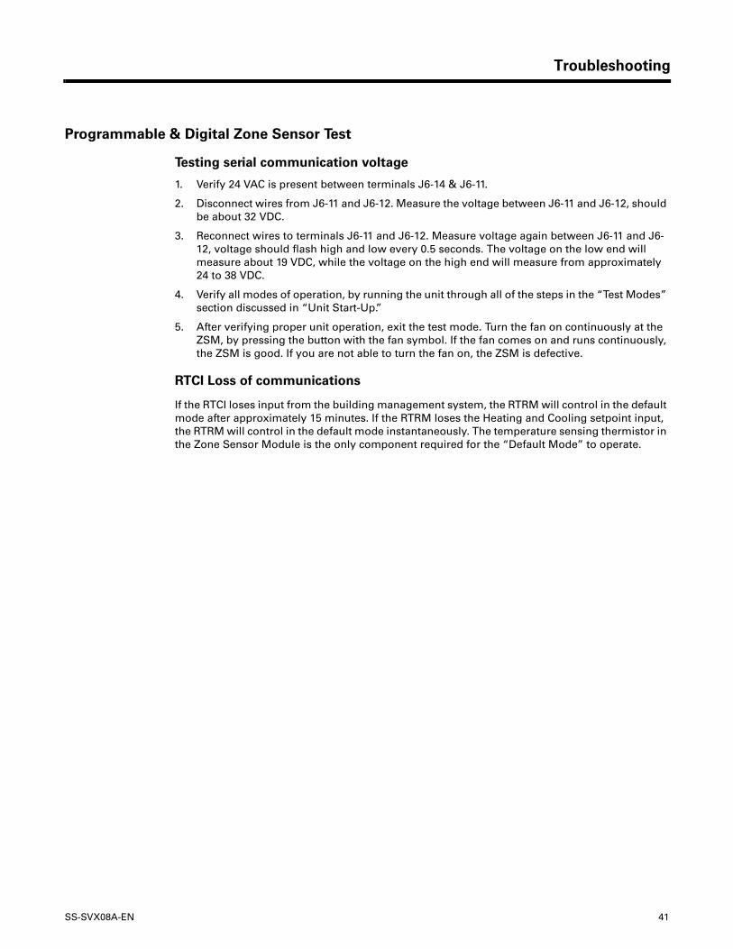
Programmable & Digital Zone Sensor Test
Testing serial communication voltage
1. Verify 24 VAC is present between terminals J6-14 & J6-11.
2. Disconnect wires from J6-11 and J6-12. Measure the voltage between J6-11 and J6-12, should be about 32 VDC.
3. Reconnect wires to terminals J6-11 and J6-12. Measure voltage again between J6-11 and J6-12, voltage should flash high and low every 0.5 seconds. The voltage on the low end will measure about 19 VDC, while the voltage on the high end will measure from approximately 24 to 38 VDC.
4. Verify all modes of operation, by running the unit through all of the steps in the “Test Modes” section discussed in “Unit Start-Up.”
5. After verifying proper unit operation, exit the test mode. Turn the fan on continuously at the ZSM, by pressing the button with the fan symbol. If the fan comes on and runs continuously, the ZSM is good. If you are not able to turn the fan on, the ZSM is defective.
RTCI Loss of communications
If the RTCI loses input from the building management system, the RTRM will control in the default mode after approximately 15 minutes. If the RTRM loses the Heating and Cooling setpoint input, the RTRM will control in the default mode instantaneously. The temperature sensing thermistor in the Zone Sensor Module is the only component required for the “Default Mode” to operate.
42 SS-SVX08A-EN
� WARNING Live Electrical Components!
During installation, testing, servicing and troubleshooting of this product, it may be
necessary to work with live electrical components. Have a qualified licensed electrician
or other individual who has been properly trained in handling live electrical
components perform these tasks. Failure to follow all electrical safety precautions
when exposed to live electrical components could result in death or serious injury.
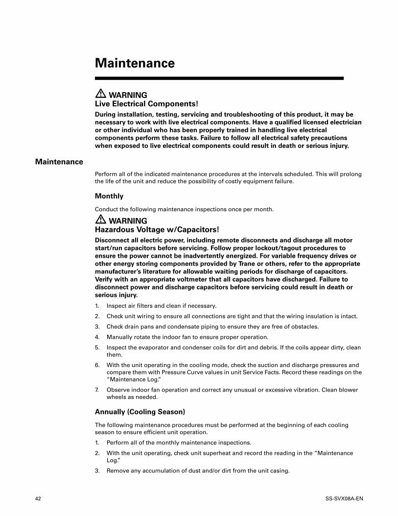
Maintenance
Perform all of the indicated maintenance procedures at the intervals scheduled. This will prolong the life of the unit and reduce the possibility of costly equipment failure.
Monthly
Conduct the following maintenance inspections once per month.
� WARNING Hazardous Voltage w/Capacitors!
Disconnect all electric power, including remote disconnects and discharge all motor
start/run capacitors before servicing. Follow proper lockout/tagout procedures to
ensure the power cannot be inadvertently energized. For variable frequency drives or
other energy storing components provided by Trane or others, refer to the appropriate
manufacturer’s literature for allowable waiting periods for discharge of capacitors.
Verify with an appropriate voltmeter that all capacitors have discharged. Failure to
disconnect power and discharge capacitors before servicing could result in death or
serious injury.
1. Inspect air filters and clean if necessary.
2. Check unit wiring to ensure all connections are tight and that the wiring insulation is intact.
3. Check drain pans and condensate piping to ensure they are free of obstacles.
4. Manually rotate the indoor fan to ensure proper operation.
5. Inspect the evaporator and condenser coils for dirt and debris. If the coils appear dirty, clean them.
6. With the unit operating in the cooling mode, check the suction and discharge pressures and compare them with Pressure Curve values in unit Service Facts. Record these readings on the “Maintenance Log.”
7. Observe indoor fan operation and correct any unusual or excessive vibration. Clean blower wheels as needed.
Annually (Cooling Season)
The following maintenance procedures must be performed at the beginning of each cooling season to ensure efficient unit operation.
1. Perform all of the monthly maintenance inspections.
2. With the unit operating, check unit superheat and record the reading in the “Maintenance Log.”
3. Remove any accumulation of dust and/or dirt from the unit casing.
Maintenance
SS-SVX08A-EN 43
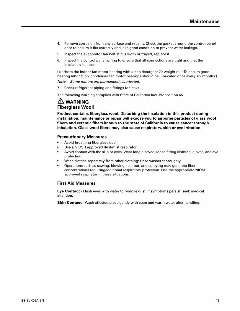
Maintenance
4. Remove corrosion from any surface and repaint. Check the gasket around the control panel door to ensure it fits correctly and is in good condition to prevent water leakage.
5. Inspect the evaporator fan belt. If it is worn or frayed, replace it.
6. Inspect the control panel wiring to ensure that all connections are tight and that the insulation is intact.
Lubricate the indoor fan motor bearing with a non detergent 20-weight oil. (To ensure good bearing lubrication, condenser fan motor bearings should be lubricated once every six months.)
Note: Some motors are permanently lubricated.
7. Check refrigerant piping and fittings for leaks.
The following warning complies with State of California law, Proposition 65.
� WARNING Fiberglass Wool!
Product contains fiberglass wool. Disturbing the insulation in this product during
installation, maintenance or repair will expose you to airborne particles of glass wool
fibers and ceramic fibers known to the state of California to cause cancer through
inhalation. Glass wool fibers may also cause respiratory, skin or eye irritation.
Precautionary Measures
• Avoid breathing fiberglass dust.• Use a NIOSH approved dust/mist respirator.• Avoid contact with the skin or eyes. Wear long-sleeved, loose-fitting clothing, gloves, and eye
protection.• Wash clothes separately from other clothing: rinse washer thoroughly.• Operations such as sawing, blowing, tear-out, and spraying may generate fiber
concentrations requiringadditional respiratory protection. Use the appropriate NIOSH approved respirator in these situations.
First Aid Measures
Eye Contact - Flush eyes with water to remove dust. If symptoms persist, seek medical attention.
Skin Contact - Wash affected areas gently with soap and warm water after handling.
44 SS-SVX08A-EN
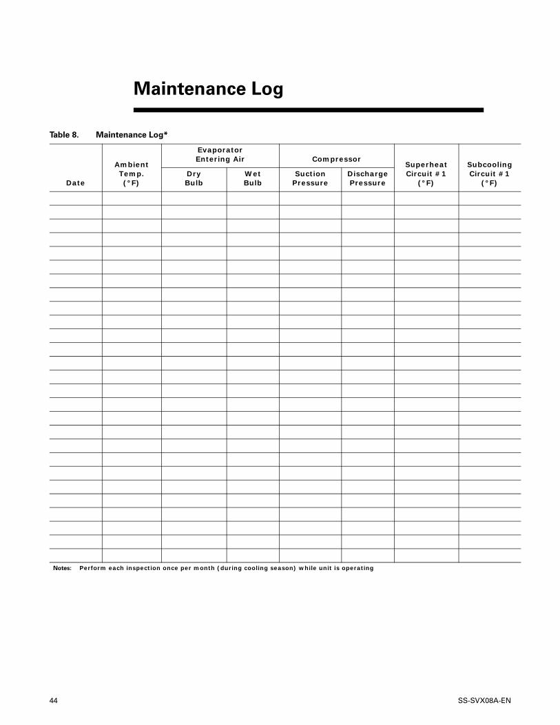
Maintenance Log
Table 8. Maintenance Log*
Date
AmbientTemp.(°F)
EvaporatorEntering Air Compressor
SuperheatCircuit #1
(°F)
SubcoolingCircuit #1
(°F)DryBulb
Wet Bulb
SuctionPressure
DischargePressure
Notes: Perform each inspection once per month (during cooling season) while unit is operating
SS-SVX08A-EN 45
TTA, TTN, TTP, TTR, TTB, TTX, TTY and TTZ (Parts Only)
This warranty is extended by Trane to the original purchaser and to any succeeding owner of the real property to which the Air Conditioner is originally affixed, and applies to products purchased and retained for use within the U.S.A. and Canada. There is no warranty against corrosion, erosion or deterioration.
If any part of your Air Conditioner fails because of a manufacturing defect within one year from the date of original purchase, Warrantor will furnish without charge the required replacement part.
In addition, if the sealed motor-compressor(s) fail(s) because of a manufacturing defect within the second through fifth year from the date of original purchase, Warrantor will furnish without charge a replacement compressor(s). Warrantor’s obligations and liabilities under this warranty are limited to furnishing F.O.B. Warrantor factory or warehouse replacement parts for Warrantor’s products covered under this warranty. Warrantor shall not be obligated to pay for the cost of lost refrigerant. No liability shall attach to Warrantor until products have been paid for and then liability shall be limited solely to the purchase price of the equipment under warranty shown to be defective.
THE WARRANTY AND LIABILITY SET FORTH HEREIN ARE IN LIEU OF ALL OTHER WARRANTIES AND LIABILITIES, WHETHER IN CONTRACT OR IN NEGLIGENCE, EXPRESS OR IMPLIED, IN LAW OR IN FACT, INCLUDING IMPLIED WARRANTIES OF MERCHANTABILITY AND FITNESS FOR PARTICULAR USE, AND IN NO EVENT SHALL WARRANTOR BE LIABLE FOR ANY INCIDENTAL OR CONSEQUENTIAL DAMAGES.
Some states do not allow limitations on how long an implied warranty lasts or do not allow the exclusion or limitation of incidental or consequential damages, so the above limitation or exclusion may not apply to you. This warranty gives you specific legal rights, and you may also have other rights which vary from state to state.
Trane, 2701 Wilma Rudolph Blvd., Clarksville, TN 37040-1008 Attention: Manager, Product Service
TW-338-0597
* This warranty is for commercial usage of said equipment and not applicable when the equipment is used for a residential application. Commercial use is any application where the end purchaser uses the product for other than personal, family or household purposes.
Commercial Equipment Rated 20 Tons and Larger and Related Accessories (Parts Only)
Products Covered — This warranty is extended by Trane, and applies only to commercial equipment rated 20 tons and larger and related accessories purchased and retained for use within the U.S.A. and Canada.
Warrantor warrants for a period of 12 months from initial start-up or 18 months from date of shipment, whichever is less, that the products covered by this warranty (1) are free from defects in material and manufacture, and (2) have the capacities and ratings set forth in catalogs and bulletins; provided, that no warranty is made against corrosion, erosion or deterioration. Warrantor’s obligations and liabilities under this warranty are limited to furnishing, F.O.B. factory replacement parts (or equipment at the option of Warrantor) for all Warrantor’s products not conforming to this warranty. Warrantor shall not be obligated to pay for the cost of lost refrigerant. No liability whatever shall attach to Warrantor until said products have been paid for and then said liability shall be limited to the purchase price of the equipment shown to be defective.
Warranty
46 SS-SVX08A-EN
Warranty
THE WARRANTY AND LIABILITY SET FORTH HEREIN ARE IN LIEU OF ALL OTHER WARRANTIES AND LIABILITIES, WHETHER IN CONTRACT OR IN NEGLIGENCE, EXPRESS OR IMPLIED, IN LAW OR IN FACT, INCLUDING IMPLIED WARRANTIES OF MERCHANTABILITY AND FITNESS FOR PARTICULAR USE, AND IN NO EVENT SHALL WARRANTOR BE LIABLE FOR ANY INCIDENTAL OR CONSEQUENTIAL DAMAGES.
Some states do not allow limitations on how long an implied warranty lasts or do not allow the exclusion or limitation of incidental or consequential damages, so the above limitation or exclusion may not apply to you. This warranty gives you specific legal rights, and you may also have other rights which vary from state to state.
Trane—Warrantor, 2701 Wilma Rudolph Blvd., Clarksville, TN 37040
GW-598-4799

SS-SVX08A-EN 47
Wiring Diagram Matrix
WIRING DIAGRAM NO. DIAGRAM TYPE UNIT MODEL NO'S
4367-0325 ElectroMechanical Connection and Schematic TTA120B3, TTA120B4, TTA120BW, TTA100BD, TTA150B3, TTA150B4, TTA150BW, TTA125BD, TTA120BK, TTA150BK
4367-0326 ElectroMechanical Connection and Schematic TTA100CD, TTA120C3, TTA120C4, TTA120CW
4367-0327 ElectroMechanical Connection and Schematic TWA090A3, TWA090A4, TWA090AW, TWA120A4, TWA120AW, TWA075AD, TWA100AD
4367-0335 ElectroMechanical Connection and Schematic TTA155BD, TTA180B3, TTA180B4, TTA180BW, TTA180BK, TTA200BD, TTA240B4, TTA240BW, TTA240BK
4367-0336 ElectroMechanical Connection and Schematic TTA240B3
4367-0337 ElectroMechanical Connection and Schematic TTA155CD, TTA180C3, TTA180C4, TTA180CW
4367-0338 ElectroMechanical Connection and Schematic TWA200BD, TWA240B4, TWA240BW
4367-0339 ElectroMechanical Connection and Schematic TWA155BD, TWA180B3, TWA180B4, TWA180BW
4367-0340 ElectroMechanical Connection and Schematic TWA240B3
4367-0341 ElectroMechanical Connection and Schematic TTA120A3
4367-0342 ElectroMechanical Connection and Schematic TTA075AD, TTA085AD,TTA090A3, TTA090A4, TTA090AW, TTA090AK, TTA100AD, TTA120A4, TTA120AW, TTA120AK
4367-0343 ElectroMechanical Connection and Schematic TWA090A3, TWA090A4, TWA090AW, TWA120A4, TWA120AW, TWA075AD, TWA100AD
4367-0344 ElectroMechanical Connection and Schematic TWA120A3
4367-0345 ReliaTel Connection and Schematic TTA240B3
4367-0346 ElectroMechanical Connection and Schematic TWE060A3, TWE060C3
4367-0347 ElectroMechanical Connection and Schematic TWE090A1, TWE120A1
4367-0349 ElectroMechanical Connection and Schematic
TWE155BD, TWE180BW, TWE180B3, TWE180B4, TWE180BK, TWE200BD, TWE240BW, TWE240B3, TWE240B4, TWE240BK, TWE155CD, TWE180CW, TWE180C3, TWE180C4, TWE180CK, TWE200CD, TWE240CW, TWE240C3, TWE240C4, TWE240CK
4367-0350 ElectroMechanical Connection and Schematic TWE090B3, TWE120B3, TWE120BK
4367-0351 ElectroMechanical Connection and Schematic TWE100BD, TWE120BW
4367-0352 ElectroMechanical Connection and Schematic TWE060B1, TWE090B1, TWE120B1
4367-0353 ElectroMechanical Connection and Schematic TWE060B3
4367-0354 ElectroMechanical Connection and Schematic TWE060B4
4367-0355 ElectroMechanical Connection and Schematic TWE090AK, TWE090A3, TWE090C3, TWE120AK, TWE120A3, TWE120C3
4367-0356 ElectroMechanical Connection and Schematic TWE060A1, TWE060C1
4367-0357 ElectroMechanical Connection and Schematic TWE050AD, TWE060AK, TWE060AW, TWE060A4, TWE060CW, TWE060C4
4367-0358 ElectroMechanical Connection and Schematic TWE075AD, TWE090AW, TWE100AD, TWE120AW, TWE090CW, TWE120CW
4367-0359 ReliaTel Connection and Schematic TTA155BD, TTA180B3, TTA180B4, TTA180BW, TTA180BK, TTA200BD, TTA240B4, TTA240BW, TTA240BK
4367-0360 ReliaTel Connection and Schematic TTA155CD, TTA180C3, TTA180C4, TTA180CW
4367-0361 ReliaTel Connection and Schematic TTA100CD, TTA120C3, TTA120C4, TTA120CW
4367-0362 ReliaTel Connection and Schematic TTA120B3, TTA120B4, TTA120BW, TTA100BD, TTA150B3, TTA150B4, TTA150BW, TTA125BD, TTA120BK, TTA150BK
4367-0363 ReliaTel Connection and Schematic TTA075AD, TTA085AD, TTA090A3, TTA090A4, TTA090AW, TTA090AK, TTA100AD, TTA120A4, TTA120AW, TTA120AK
4367-0364 ReliaTel Connection and Schematic TTA120A3
4367-0444 ReliaTel Connection and Schematic TTA200FD, TTA240F4, TTA240FW, and TTA240FK
Notes: Wiring diagrams are available via e-Library.
Literature Order Number SS-SVX08A-EN
Date May 2008
Supersedes SS-SVX08A-EN (December 2007)
The manufacturer has a policy of continuous product and product data improvement and reserves the right to change design and specifications without notice.