Trane Split System Cooling Product and Performance Data
12
Three Phase 4TTA3030-060 2½ – 5 Tons Split System Cooling Product & Performance Data PUB. NO. 22-1791-05
Transcript of Trane Split System Cooling Product and Performance Data
Three Phase4TTA3030-060
2½ – 5 Tons
Split SystemCooling Product& Performance Data
PUB. NO. 22-1791-05
© 2009 Trane 2 22-1791-05
Features andBenefits
• Climatuff® compressor
• All aluminum Spine Fin™ coil
• WeatherGuard™ fasteners
• Quick-Sess™ cabinet, serviceaccess and refrigerant connectionswith full coil protection
• DuraTuff™ base, fast complete drain,weatherproof
• Comfort “R”™ mode approved
• Glossy corrosion resistant finish
• Internal compressor high/low pressureand temperature protection
• Liquid line filter-drier
• Polyslate gray cabinet with anthracitegray badge and cap
• R-410A refrigerant
• Low Pressure Switch
• High Pressure Switch
• Compressor Sump Heat
• S.E.E.T. design testing
• 100% line run test
• Low ambient cooling to 55°F asshipped
• Low ambient cooling to 30°F withAY28X079
• Low ambient cooling to 0°F withBAYLOAM103
• Extended warranties available
22-1791-05 3
Contents
Features and Benefits 2
General Data 4Product Specifications 4A-weighted Sound Power Level [dB(A)] 4Accessory Description and Usage 5ARI Standard Capacity Rating Conditions 5
Model Nomenclature 7
Electrical Data 8
Dimensions 11
Mechanical Specification Options 12

4 22-1791-05
Product SpecificationsModel No. 1 4TTA3030A3 4TTA3030A4 4TTA3036A3 4TTA3036A4Electrical Data V/Ph/Hz 2 200/230/3/60 460/3/60 200/230/3/60 460/3/60Min Cir Ampacity 10 5 15 7Max Fuse Size (Amps) 15 15 25 15Compressor CLIMATUFF® CLIMATUFF® CLIMATUFF® - SCROLL CLIMATUFF® - SCROLLRL Amps - LR Amps 7.4 - 54.9 3.7 - 28 11.5 - 77 5.1 - 35Outdoor Fan FL Amps 0.7 0.4 0.7 0.4Fan HP 1/8 1/8 1/8 1/8Fan Dia (inches) 23.0 23.0 23.0 23.0Coil Spine Fin™ Spine Fin™ Spine Fin™ Spine Fin™Refrigerant R-410A 5/11-LB/OZ 5/11-LB/OZ 6/07-LB/OZ 6/07-LB/OZLine Size - (in.) O.D. Gas 3 3/4 3/4 3/4 3/4Line Size - (in.) O.D. Liquid 3 3/8 3/8 3/8 3/8Charge Spec. Subcooling 10° 10° 10° 10°Dimensions H x W x D (Crated) 38 x 30.1 x 33 38 x 30.1 x 33 42 x 30.1 x 33 42 x 30.1 x 33Weight - Shipping 224 222 229 227Weight - Net 197 195 201 199Start Components NO NO NO NOSound Enclosure NO NO NO NOCompressor Sump Heat YES YES YES YESOptional Accessories: 4Anti-short Cycle Timer TAYASCT501A TAYASCT501A TAYASCT501A TAYASCT501AEvaporator Defrost Control AY28X079 AY28X079 AY28X079 AY28X079Rubber Isolator Kit BAYISLT101 BAYISLT101 BAYISLT101 BAYISLT101Snow/Sand Legs - Base & Cap 4" High BAYLEGS002 BAYLEGS002 BAYLEGS002 BAYLEGS002Snow/Sand Legs - 4" Extension BAYLEGS003 BAYLEGS003 BAYLEGS003 BAYLEGS003Indoor Fan Delay Kit BAY24X045 BAY24X045 BAY24X045 BAY24X045Sound Enclosure BAYSDEN001 BAYSDEN001 BAYSDEN003 BAYSDEN003Extreme Condition Mounting Kit BAYECMT001 BAYECMT001 BAYECMT001 BAYECMT001Seacoast Kit BAYSEAC001 BAYSEAC001 BAYSEAC001 BAYSEAC001Low Ambient Kit BAYLOAM103 BAYLOAM103 BAYLOAM103 BAYLOAM103Refrigerant Lineset 5 TAYREFLN2* TAYREFLN2* TAYREFLN7* TAYREFLN7*1 Certified in accordance with the Unitary Air-Conditioner equipment certification program which is based on ARI Standard 210/240.2 Calculated in accordance with N.E.C. Only use HACR circuit breakers or fuses.3 Standard line lengths - 60'. Standard lift - 60' Suction and Liquid line.
For Greater lengths and lifts refer to refrigerant piping software Pub# 32-3312-0†. (†denotes latest revision)4 For accessory description and usage, see page 5.5 * = 15, 20, 25, 30, 40 and 50 foot lineset available.
GeneralData
22-1791-05
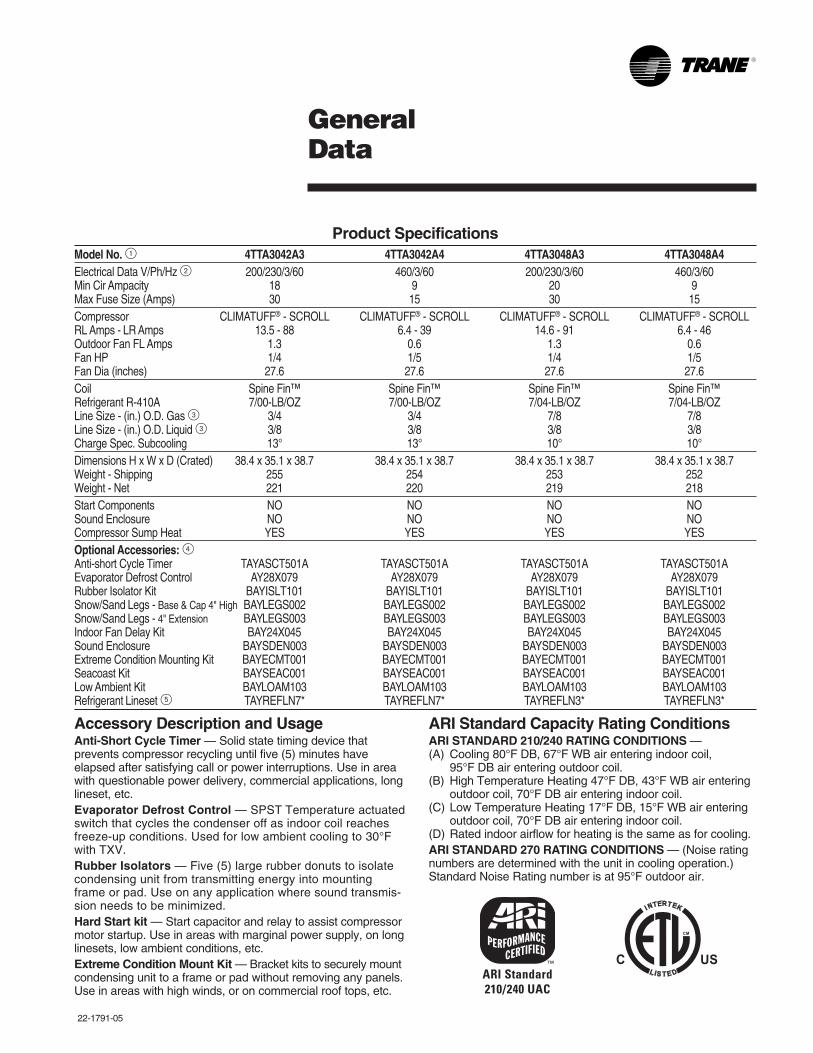
Product SpecificationsModel No. 1 4TTA3042A3 4TTA3042A4 4TTA3048A3 4TTA3048A4Electrical Data V/Ph/Hz 2 200/230/3/60 460/3/60 200/230/3/60 460/3/60Min Cir Ampacity 18 9 20 9Max Fuse Size (Amps) 30 15 30 15Compressor CLIMATUFF® - SCROLL CLIMATUFF® - SCROLL CLIMATUFF® - SCROLL CLIMATUFF® - SCROLLRL Amps - LR Amps 13.5 - 88 6.4 - 39 14.6 - 91 6.4 - 46Outdoor Fan FL Amps 1.3 0.6 1.3 0.6Fan HP 1/4 1/5 1/4 1/5Fan Dia (inches) 27.6 27.6 27.6 27.6Coil Spine Fin™ Spine Fin™ Spine Fin™ Spine Fin™Refrigerant R-410A 7/00-LB/OZ 7/00-LB/OZ 7/04-LB/OZ 7/04-LB/OZLine Size - (in.) O.D. Gas 3 3/4 3/4 7/8 7/8Line Size - (in.) O.D. Liquid 3 3/8 3/8 3/8 3/8Charge Spec. Subcooling 13° 13° 10° 10°Dimensions H x W x D (Crated) 38.4 x 35.1 x 38.7 38.4 x 35.1 x 38.7 38.4 x 35.1 x 38.7 38.4 x 35.1 x 38.7Weight - Shipping 255 254 253 252Weight - Net 221 220 219 218Start Components NO NO NO NOSound Enclosure NO NO NO NOCompressor Sump Heat YES YES YES YESOptional Accessories: 4Anti-short Cycle Timer TAYASCT501A TAYASCT501A TAYASCT501A TAYASCT501AEvaporator Defrost Control AY28X079 AY28X079 AY28X079 AY28X079Rubber Isolator Kit BAYISLT101 BAYISLT101 BAYISLT101 BAYISLT101Snow/Sand Legs - Base & Cap 4" High BAYLEGS002 BAYLEGS002 BAYLEGS002 BAYLEGS002Snow/Sand Legs - 4" Extension BAYLEGS003 BAYLEGS003 BAYLEGS003 BAYLEGS003Indoor Fan Delay Kit BAY24X045 BAY24X045 BAY24X045 BAY24X045Sound Enclosure BAYSDEN003 BAYSDEN003 BAYSDEN003 BAYSDEN003Extreme Condition Mounting Kit BAYECMT001 BAYECMT001 BAYECMT001 BAYECMT001Seacoast Kit BAYSEAC001 BAYSEAC001 BAYSEAC001 BAYSEAC001Low Ambient Kit BAYLOAM103 BAYLOAM103 BAYLOAM103 BAYLOAM103Refrigerant Lineset 5 TAYREFLN7* TAYREFLN7* TAYREFLN3* TAYREFLN3*
GeneralData
ARI Standard Capacity Rating ConditionsARI STANDARD 210/240 RATING CONDITIONS —(A) Cooling 80°F DB, 67°F WB air entering indoor coil,
95°F DB air entering outdoor coil.(B) High Temperature Heating 47°F DB, 43°F WB air entering
outdoor coil, 70°F DB air entering indoor coil.(C) Low Temperature Heating 17°F DB, 15°F WB air entering
outdoor coil, 70°F DB air entering indoor coil.(D) Rated indoor airflow for heating is the same as for cooling.ARI STANDARD 270 RATING CONDITIONS — (Noise ratingnumbers are determined with the unit in cooling operation.)Standard Noise Rating number is at 95°F outdoor air.
Accessory Description and UsageAnti-Short Cycle Timer — Solid state timing device thatprevents compressor recycling until five (5) minutes haveelapsed after satisfying call or power interruptions. Use in areawith questionable power delivery, commercial applications, longlineset, etc.Evaporator Defrost Control — SPST Temperature actuatedswitch that cycles the condenser off as indoor coil reachesfreeze-up conditions. Used for low ambient cooling to 30°Fwith TXV.Rubber Isolators — Five (5) large rubber donuts to isolatecondensing unit from transmitting energy into mountingframe or pad. Use on any application where sound transmis-sion needs to be minimized.Hard Start kit — Start capacitor and relay to assist compressormotor startup. Use in areas with marginal power supply, on longlinesets, low ambient conditions, etc.Extreme Condition Mount Kit — Bracket kits to securely mountcondensing unit to a frame or pad without removing any panels.Use in areas with high winds, or on commercial roof tops, etc.
6 22-1791-05
GeneralData
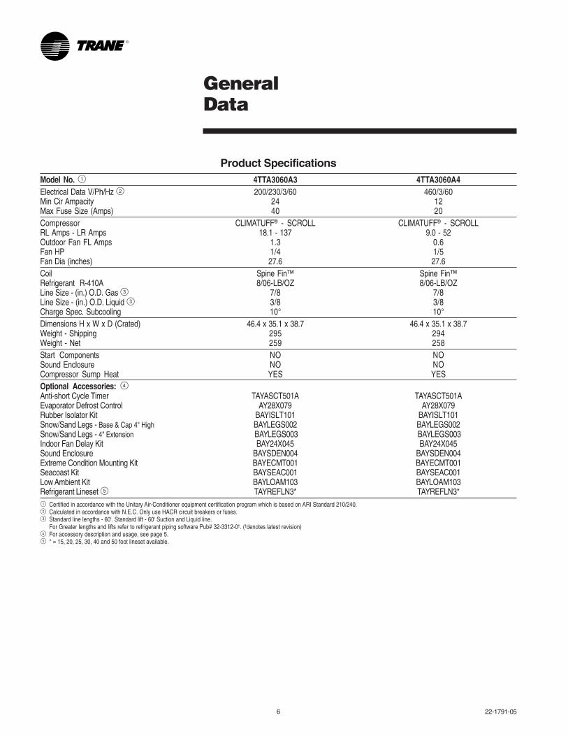
Product SpecificationsModel No. 1 4TTA3060A3 4TTA3060A4Electrical Data V/Ph/Hz 2 200/230/3/60 460/3/60Min Cir Ampacity 24 12Max Fuse Size (Amps) 40 20Compressor CLIMATUFF® - SCROLL CLIMATUFF® - SCROLLRL Amps - LR Amps 18.1 - 137 9.0 - 52Outdoor Fan FL Amps 1.3 0.6Fan HP 1/4 1/5Fan Dia (inches) 27.6 27.6Coil Spine Fin™ Spine Fin™Refrigerant R-410A 8/06-LB/OZ 8/06-LB/OZLine Size - (in.) O.D. Gas 3 7/8 7/8Line Size - (in.) O.D. Liquid 3 3/8 3/8Charge Spec. Subcooling 10° 10°Dimensions H x W x D (Crated) 46.4 x 35.1 x 38.7 46.4 x 35.1 x 38.7Weight - Shipping 295 294Weight - Net 259 258Start Components NO NOSound Enclosure NO NOCompressor Sump Heat YES YESOptional Accessories: 4Anti-short Cycle Timer TAYASCT501A TAYASCT501AEvaporator Defrost Control AY28X079 AY28X079Rubber Isolator Kit BAYISLT101 BAYISLT101Snow/Sand Legs - Base & Cap 4" High BAYLEGS002 BAYLEGS002Snow/Sand Legs - 4" Extension BAYLEGS003 BAYLEGS003Indoor Fan Delay Kit BAY24X045 BAY24X045Sound Enclosure BAYSDEN004 BAYSDEN004Extreme Condition Mounting Kit BAYECMT001 BAYECMT001Seacoast Kit BAYSEAC001 BAYSEAC001Low Ambient Kit BAYLOAM103 BAYLOAM103Refrigerant Lineset 5 TAYREFLN3* TAYREFLN3*1 Certified in accordance with the Unitary Air-Conditioner equipment certification program which is based on ARI Standard 210/240.2 Calculated in accordance with N.E.C. Only use HACR circuit breakers or fuses.3 Standard line lengths - 60'. Standard lift - 60' Suction and Liquid line.
For Greater lengths and lifts refer to refrigerant piping software Pub# 32-3312-0†. (†denotes latest revision)4 For accessory description and usage, see page 5.5 * = 15, 20, 25, 30, 40 and 50 foot lineset available.
22-1791-05 7
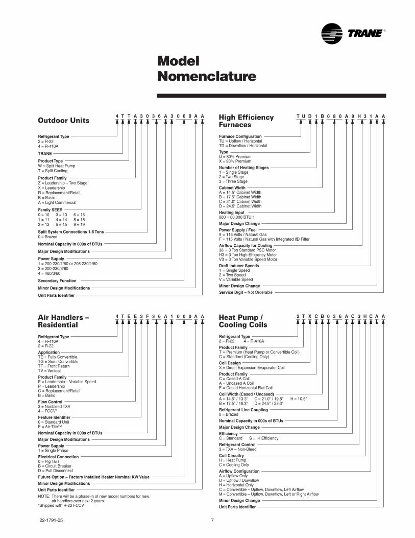
ModelNomenclature
Refrigerant Type2 = R-224 = R-410A
TRANE
Product TypeW = Split Heat PumpT = Split Cooling
Product FamilyZ = Leadership – Two StageX = LeadershipR = Replacement/RetailB = BasicA = Light Commercial
Family SEER0 = 10 3 = 13 6 = 161 = 11 4 = 14 8 = 182 = 12 5 = 15 9 = 19
Split System Connections 1-6 Tons0 = Brazed
Nominal Capacity in 000s of BTUs
Major Design Modifications
Power Supply1 = 200-230/1/60 or 208-230/1/603 = 200-230/3/604 = 460/3/60
Secondary Function
Minor Design Modifications
Unit Parts Identifier
Outdoor Units4 T T A 3 0 3 6 A 3 0 0 0 A A
Refrigerant Type4 = R-410A2 = R-22
ApplicationTE = Fully ConvertibleTG = Semi ConvertibleTF = Front ReturnTV = Vertical
Product FamilyE = Leadership – Variable SpeedP = LeadershipC = Replacement/RetailB = Basic
Flow Control3 = Nonbleed TXV4 = FCCV*
Feature Identifier0 = Standard UnitF = Air-Tite™
Nominal Capacity in 000s of BTUs
Major Design Modifications
Power Supply1 = Single Phase
Electrical Connection0 = Pig TailsB = Circuit BreakerD = Pull Disconnect
Future Option – Factory Installed Heater Nominal KW Value
Minor Design Modifications
Unit Parts Identifier
NOTE: There will be a phase-in of new model numbers for new air handlers over next 2 years.*Shipped with R-22 FCCV
Air Handlers –Residential
4 T E E 3 F 3 6 A 1 A A0 0 0
Furnace ConfigurationTU = Upflow / HorizontalTD = Downflow / Horizontal
TypeD = 80% PremiumX = 90% Premium
Number of Heating Stages1 = Single Stage2 = Two Stage3 = Three Stage
Cabinet WidthA = 14.5" Cabinet WidthB = 17.5" Cabinet WidthC = 21.0" Cabinet WidthD = 24.5" Cabinet Width
Heating Input080 = 80,000 BTUH
Major Design Change
Power Supply / Fuel9 = 115 Volts / Natural GasF = 115 Volts / Natural Gas with Integrated ifD Filter
Airflow Capacity for Cooling36 = 3 Ton Standard PSC MotorH3 = 3 Ton High Efficiency MotorV3 = 3 Ton Variable Speed Motor
Draft Inducer Speeds1 = Single Speed2 = Two SpeedV = Variable Speed
Minor Design Change
Service Digit – Not Orderable
T U D 1 B 0 8 0 A 9 H 3 1 A AHigh Efficiency Furnaces
Refrigerant Type2 = R-22 4 = R-410A
Product FamilyT = Premium (Heat Pump or Convertible Coil)C = Standard (Cooling Only)
Coil DesignX = Direct Expansion Evaporator Coil
Product FamilyC = Cased A CoilA = Uncased A CoilF = Cased Horizontal Flat Coil
Coil Width (Cased / Uncased)A = 14.5" / 13.3" C = 21.0" / 19.8" H = 10.5"B = 17.5" / 16.3" D = 24.5" / 23.3"
Refrigerant Line Coupling0 = Brazed
Nominal Capacity in 000s of BTUs
Major Design Change
EfficiencyC = Standard S = Hi Efficiency
Refrigerant Control3 = TXV – Non-Bleed
Coil CircuitryH = Heat PumpC = Cooling Only
Airflow ConfigurationA = Upflow OnlyU = Upflow / DownflowH = Horizontal OnlyC = Convertible – Upflow, Downflow, Left AirflowM = Convertible – Upflow, Downflow, Left or Right Airflow
Minor Design Change
Unit Parts Identifier
Heat Pump /Cooling Coils
2 T X C B 0 3 6 A C 3 H C A A
8 22-1791-05
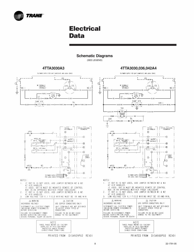
4TTA3030A3 4TTA3030,036,042A4
ElectricalData
Schematic Diagrams(SEE LEGEND)
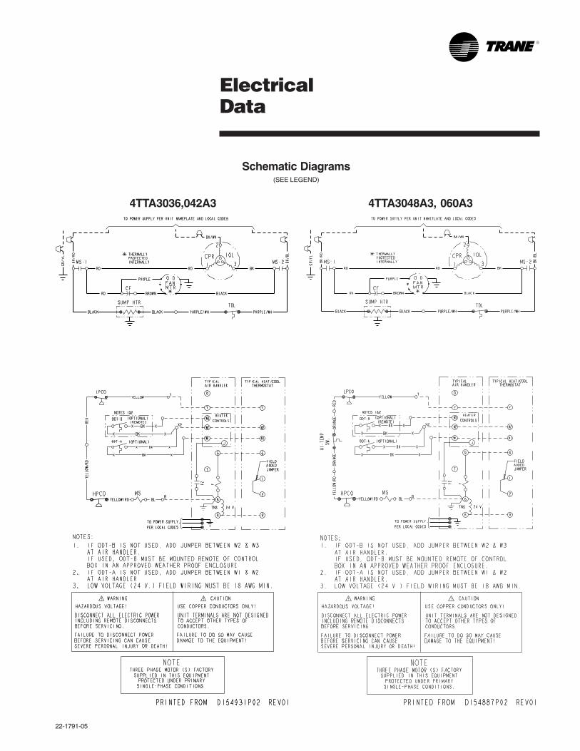
22-1791-05
4TTA3036,042A3
ElectricalData
Schematic Diagrams(SEE LEGEND)
4TTA3048A3, 060A3
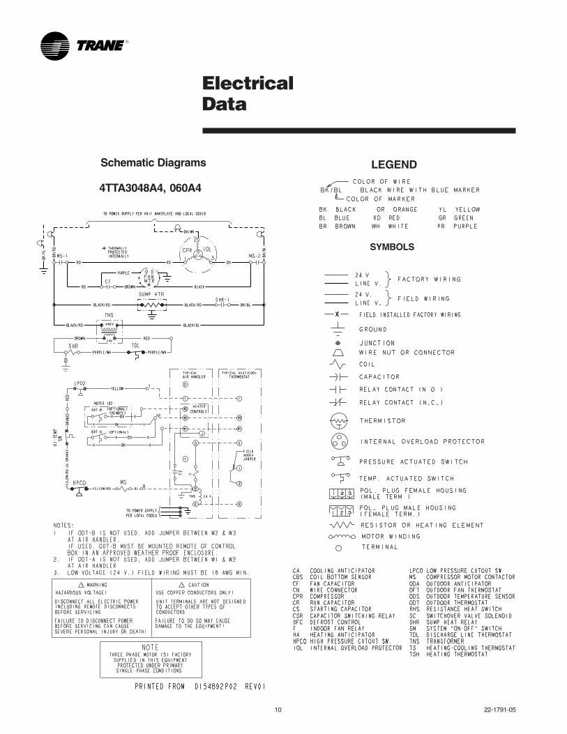
10 22-1791-05
4TTA3048A4, 060A4
LEGEND
ElectricalData
Schematic Diagrams
SYMBOLS
22-1791-05
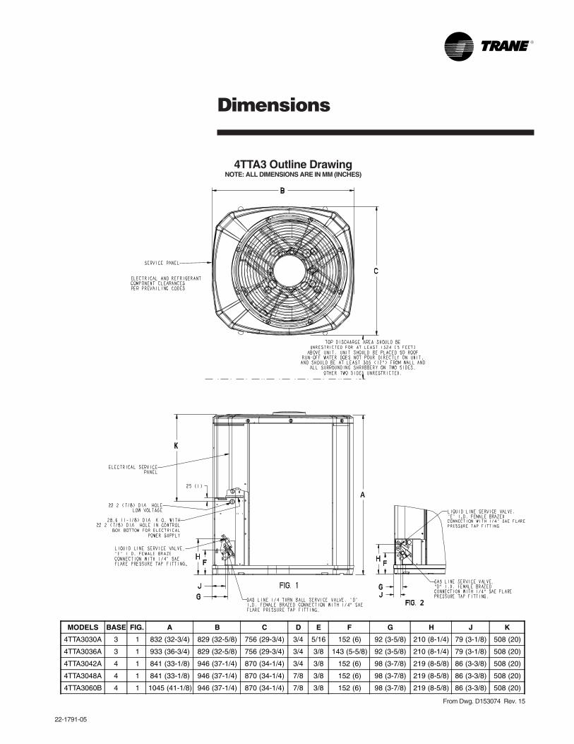
Dimensions
4TTA3 Outline DrawingNOTE: ALL DIMENSIONS ARE IN MM (INCHES)
MODELS BASE FIG. A B C D E F G H J K
4TTA3030A 3 1 832 (32-3/4) 829 (32-5/8) 756 (29-3/4) 3/4 5/16 152 (6) 92 (3-5/8) 210 (8-1/4) 79 (3-1/8) 508 (20)
4TTA3036A 3 1 933 (36-3/4) 829 (32-5/8) 756 (29-3/4) 3/4 3/8 143 (5-5/8) 92 (3-5/8) 210 (8-1/4) 79 (3-1/8) 508 (20)
4TTA3042A 4 1 841 (33-1/8) 946 (37-1/4) 870 (34-1/4) 3/4 3/8 152 (6) 98 (3-7/8) 219 (8-5/8) 86 (3-3/8) 508 (20)
4TTA3048A 4 1 841 (33-1/8) 946 (37-1/4) 870 (34-1/4) 7/8 3/8 152 (6) 98 (3-7/8) 219 (8-5/8) 86 (3-3/8) 508 (20)
4TTA3060B 4 1 1045 (41-1/8) 946 (37-1/4) 870 (34-1/4) 7/8 3/8 152 (6) 98 (3-7/8) 219 (8-5/8) 86 (3-3/8) 508 (20)
From Dwg. D153074 Rev. 15
12 22-1791-05
MechanicalSpecification Options
GeneralThe 4TTA3 shall be fully charged fromthe factory for matched indoor sectionand up to 15 feet of piping. This unitmust be designed to operate at outdoorambient temperatures as high as 115°F.Cooling capacities shall be matched witha wide selection of air handlers andfurnace coils that are ARI certified. Theunit is certified to UL 1995 application.
CasingUnit casing is constructed of heavygauge, galvanized steel and paintedwith a weather-resistant powder paint.Corrosion and weatherproof CMBP-G30DuraTuff™ base.
Refrigerant ControlsRefrigeration system controls includecondenser fan and compressor contactor.High and low pressure controls areinherent to the compressor. Anotherstandard feature is the liquid line dryer.
CompressorThe Climatuff® compressor featuresinternal over temperature and pressureprotector, total dipped hermetic motorand thermostatically controlled sumpheater. Other features include: roto locksuction and discharge refrigerationconnections, centrifugal oil pump, andlow vibration and noise.
Condenser CoilThe Spine Fin™ coil shall be continu-ously wrapped, corrosion resistant allaluminum with minimum brazed joints.This coil is 5/16 inch O.D. seamlessaluminum glued to a continuous alumi-num fin. Coils are lab tested to withstand2,000 pounds of pressure per squareinch. The outdoor coil provides lowairflow resistance and efficient heattransfer. The coil is protected on all foursides by louvered panels.
Low Ambient CoolingAs manufactured, this unit has a coolingcapability to 55°F. The addition of anevaporator defrost control permitsoperation to 30°F. The addition of a lowambient kit permits low ambient coolingto 0°F.
AccessoriesThermostats — Heating/Cooling(manual and automatic changeover).Sub-base to match thermostat andlocking thermostat cover.
Evaporator Defrost Control —See Low Ambient Cooling.
Outdoor Thermostat — Supplementalheat outdoor ambient lockout from46 to –10°F.
07/09
Trane has a policy of continuous product and product data improvement and it reserves the right to changedesign and specifications without notice.
TraneA business ofAmerican Standard Companieswww.trane.com