SPIRA-TROL Two-port Control Valves EN Standard JE, JF and ... · Manual handling of large and / or...
32
SPIRA-TROL Two-port Control Valves EN Standard JE, JF and JL DN15 to DN200 and ASME Standard JEA, JFA and JLA ½" to 8" Installation and Maintenance Instructions 1. Safety information 2. General product information 3. Installation and commissioning 4. Maintenance DN15 - DN100 5. Maintenance DN125 - DN200 6. Spare parts IM-S24-61 CH Issue 1 3750100/1 © Copyright 2013 Printed in France
Transcript of SPIRA-TROL Two-port Control Valves EN Standard JE, JF and ... · Manual handling of large and / or...
IM-S24-61 CH Issue 1 1
SPIRA-TROL Two-port Control ValvesEN Standard JE, JF and JL DN15 to DN200 and
ASME Standard JEA, JFA and JLA ½" to 8"Installation and Maintenance Instructions
1. Safety information
2. General product information
3. Installation and commissioning
4. Maintenance DN15 - DN100
5. Maintenance DN125 - DN200
6. Spare parts
Printed in France
IM-S24-61CH Issue 1
3750100/1
© Copyright 2013
Printed in France

IM-S24-61 CH Issue 12
1.1 Intended use
1. Safety informationSafe operation of these products can only be guaranteed if they are properly installed, commissioned, used and maintained by qualified personnel (see Section 1.11) in compliance with the operating instructions. General installationand safety instructions for pipeline and plant construction, as well as the properuse of tools and safety equipment must also be complied with.
Safety note - Handling precautionsPTFEWithin its working temperature range PTFE is a completely inert material, but when heated to its sintering temperature it gives rise to gaseous decomposition products or fumes which can produce unpleasant effects if inhaled. The inhalation of these fumes is easily prevented by applying local exhaust ventilation to atmosphere as near to their source as possible.Smoking should be prohibited in workshops where PTFE is handled because tobacco contaminated with PTFE will during burning give rise to polymer fumes. It is therefore important to avoid contamination of clothing, especially the pockets, with PTFE and to maintain a reasonable standard or personal cleanliness by washing hands and removing any PTFE particles lodged under the fingernails.
Referring to the Installation and Maintenance Instructions, name-plate and Technical Information Sheet, check that the product is suitable for the intended use / application. The products listed in the Table on page 3 comply with the requirements of the European Pressure Equipment Directive 97 / 23 / EC, carry the mark when so required and fall within the Pressure Equipment Directive categories stated.
i) The products have been specifically designed for use on steam, air or condensate which are in Group 2 of the above mentioned Pressure Equipment Directive. They can also be used on fluids, gases and liquids which are in Group 1. The products’ use on other fluids may be possible but, if this is contemplated, Spirax Sarco should be contacted to confirm the suitability of the product for the application being considered.
ii) Check material suitability, pressure and temperature and their maximum and minimum values. If the maximum operating limits of the product are lower than those of the system in which it is being fitted, or if malfunction of the product could result in a dangerous overpressure or overtemperature occurrence, ensure a safety device is included in the system to prevent such over-limit situations.
iii) Determine the correct installation situation and direction of fluid flow.
iv) Spirax Sarco products are not intended to withstand external stresses that may be induced by any system to which they are fitted. It is the responsibility of the installer to consider these stresses and take adequate precautions to minimise them.
v) Remove protection covers from all connections and protective film from all name-plates, where appropriate, before installation on steam or other high
temperature applications.

IM-S24-61 CH Issue 1 3
JE valves
Size Material Group 1Gases
Group 2Gases
Group 1Liquids
Group 2Liquids
DN15DN20DN25
1.0619+N / WCB1.7357 / WC61.4408 / CF8M
SEP SEP SEP SEP
DN321.0619+N / WCB1.7357 / WC61.4408 / CF8M
2 SEP 2 SEP
DN40DN50DN65DN80DN100
1.0619+N / WCB1.7357 / WC61.4408 / CF8M
2 1 2 SEP
DN125DN150DN200
1.0619+N / WCB1.7357 / WC61.4408 / CF8M
3 2 2 SEP
1.2 AccessEnsure safe access and if necessary a safe working platform (suitably guarded) before attempting to work on the product. Arrange suitable lifting gear if required.
1.3 LightingEnsure adequate lighting, particularly where detailed or intricate work is required.
1.4 Hazardous liquids or gases in the pipelineConsider what is in the pipeline or what may have been in the pipeline at some previous time. Consider: flammable materials, substances hazardous to health, extremes of temperature.
1.5 Hazardous environment around the productConsider: explosion risk areas, lack of oxygen (e.g. tanks, pits), dangerous gases, extremes of temperature, hot surfaces, fire hazard (e.g. during welding), excessive noise, moving machinery.
1.6 The systemConsider the effect on the complete system of the work proposed. Will any proposed action (e.g. closing isolation valves, electrical isolation) put any other part of the system or any personnel at risk?Dangers might include isolation of vents or protective devices or the rendering ineffective of controls or alarms. Ensure isolation valves are turned on and off in a gradual way to avoid system shocks.
IM-S24-61 CH Issue 14
1.7 Pressure systemsEnsure that any pressure is isolated and safely vented to atmospheric pressure. Consider double isolation (double block and bleed) and the locking or labelling of closed valves. Do not assume that the system has depressurised even when the pressure gauge indicates zero.
1.8 TemperatureAllow time for temperature to normalise after isolation to avoid the danger of burns and consider whether protective clothing (including safety glasses) is required.
PTFE SEALS If seals made from PTFE have been subjected to a temperature approaching 260°C (500°F) or higher, they will give off toxic fumes, which if inhaled are likely to cause temporary discomfort. It is essential for a no smoking rule to be enforced in all areas where PTFE is stored, handled or processed as persons inhaling the fumes from burning tobacco contaminated with PTFE particles can develop 'polymer fume fever'.
1.9 Tools and consumablesBefore starting work ensure that you have suitable tools and / or consumables available. Use only genuine Spirax Sarco replacement parts.
1.10 Protective clothingConsider whether you and / or others in the vicinity require any protective clothing to protect against the hazards of, for example, chemicals, high / low temperature, radiation, noise, falling objects, and dangers to eyes and face.
1.11 Permits to workAll work must be carried out or be supervised by a suitably competent person.Installation and operating personnel should be trained in the correct use of the product according to the Installation and Maintenance Instructions.Where a formal 'permit to work' system is in force it must be complied with. Where there is no such system, it is recommended that a responsible person should know what work is going on and, where necessary, arrange to have an assistant whose primary responsibility is safety. Post ‘warning notices’ if necessary.
1.12 HandlingManual handling of large and / or heavy products may present a risk of injury. Lifting, pushing, pulling, carrying or supporting a load by bodily force can cause injury particularly to the back. You are advised to assess the risks taking into account the task, the individual, the load and the working environment and use the appropriate handling method depending on the circumstances of the work being done.
IM-S24-61 CH Issue 1 5
1.13 Residual hazardsIn normal use the external surface of the product may be very hot. If used at the maximum permitted operating conditions the surface temperature of some products may reach temperatures of 590°C (1094°F).Many products are not self-draining. Take due care when dismantling or removing the product from an installation (refer to ‘Maintenance instructions’).
1.14 FreezingProvision must be made to protect products which are not self-draining against frost damage in environments where they may be exposed to temperatures below freezing point.
1.15 DisposalUnless otherwise stated in the Installation and Maintenance Instructions, this product is recyclable and no ecological hazard is anticipated with its disposal providing due care is taken. However, if the valve is fitted with a Viton or PTFE seat, special care must be taken to avoid potential health hazards associated with decomposition / burning of these seats.
PTFE:- Can only be disposed of by approved methods, not incineration.- Keep PTFE waste in a separate container, do not mix it with other rubbish, and consign it to a landfill site.
1.16 Returning productsCustomers and stockists are reminded that under EC Health, Safety andEnvironment Law, when returning products to Spirax Sarco they must provideinformation on any hazards and the precautions to be taken due to contaminationresidues or mechanical damage which may present a health, safety orenvironmental risk. This information must be provided in writing includingHealth and Safety data sheets relating to any substances identified as hazardousor potentially hazardous.

IM-S24-61 CH Issue 16
2. General product information2.1 General descriptionSPIRA-TROL is a range of two-port single seat globe valves with cage-retained seats conforming to either EN (DIN) or ASME standards. These valves are available in three body materials. When used in conjunction with a pneumatic or electric linear actuator they provide modulating control or on / off service.
SPIRA-TROL valve characteristic - options:
JE and JEA Equal percentage (E) - Suitable for most modulating process control applications providing good control at low flowrates. JF and JFA Fast opening (F) - For on / off applications only.
JL and JLA Linear (L) - Primarily for liquid flow control where the differential pressures across the valve is constant.
Important note: Throughout this document, reference has been made to the standard JE, JEA control valves. With the exception of trim type, all derivatives are identical.
SPIRA-TROL two-port control valves are compatible with the following actuators and positioners:
Electric DN15 - DN100: EL3500, AEL5 and AEL6
DN125 - DN200: EL5600
Pneumatic All sizes: PN1000, PN9000
DN125 - DN200 : PN1000 , PN9000 and TN2000
PP5 (pneumatic) or EP5 (electropneumatic)
ISP5 (intrinsically safe electropneumatic)
Positioners SP200is, SP400 and SP500 (microprocessor based electropneumatic)
SP500 HART®
SP300 (digital communications)
Refer to the relevant Technical Information sheet for further details.
2.2 Technical data Plug design Parabolic Metal-to-metal JE series Class IV JEA series ASME Class IV
Leakage JE series Unbalanced Class VI
Soft seal Balanced Class IV JEA series Unbalanced ASME Class VI Balanced ASME Class IVRangeability 50:1 DN15 to DN50 (½" to 2") 20 mm (¾")Travel DN65 to DN100 (2½" to 4") 30 mm (1 ") DN125 to DN200 (5" to 8") 70 mm (2¾") JE See Section 2.3Pressure / temperature limits JEA See Section 2.5
IM-S24-61 CH Issue 1 7
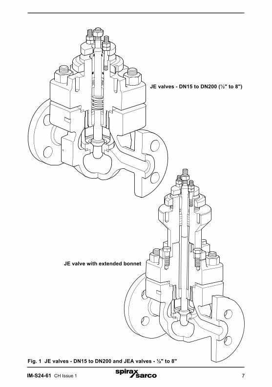
Fig. 1 JE valves - DN15 to DN200 and JEA valves - ½" to 8"
JE valves - DN15 to DN200 (½" to 8")
JE valve with extended bonnet

IM-S24-61 CH Issue 18
2.3 Pressure / temperature limits - JE43 and JEA43
Body design conditions PN100 / ASME Class 600
PMA
and
PMO
Maximum allowable pressure
Maximum operating pressure
ENPN63 JE43 63 bar g @ 50°C
PN100 JE43 100 bar g @ 50°C
ASME 600, Butt-weld andSocket weld
JEA43 102.1 bar g @ 38°C(1 480 psi g @ 100°F)
JIS / KS 30 JEA43 51 bar g @ 120°C
JIS / KS 40 JEA43 68 bar g @ 120°C
TMAMaximum allowable temperature
EN JE43 400°C
ASME 600, Butt-weld andSocket weld
JEA43 425°C (797°F)
JIS / KS 30 JEA43 425°C
JIS / KS 40 JEA43 425°C
Minimum allowable temperature-29°C
(-20°F)
TMOMaximum operating temperature
For clarification of the Options see below
Standard packing PTFE chevron (Stem sealing - Options P and N) 250°C
High temperature packing (Stem sealing - Option H) 425°C
Extended bonnet with PTFE chevron 250°C
Extended bonnet with graphite packing 425°C
PTFE soft seat (Seating - Option G) 200°C
PEEK soft seat (Seating - Options K and P) 250°C
Minimum operating temperature Note: For lower operating temperatures consult Spirax Sarco.
-29°C(-20°F)
Designed for a maximum cold hydraulic test pressure of: 156 bar g
(2 262 psi g)
Options
Stem sealingH = GraphiteN = PTFE and Nitronic bearingP = PTFE
SeatingG = PTFE soft seat K = PEEK soft seatP = Full PEEK

IM-S24-61 CH Issue 1 9
The product must not be used in this region.
Extended cover is required for use in this region.
High temperature packing required for use on this region.
A - B Flanged EN 1092 PN63 A - C Flanged EN 1092 PN100 A - D Flanged JIS / KS 30 A - E Flanged JIS / KS 40 A - F Flanged ASME 600, Butt-weld and Socket weld
Notes: 1. Where the process fluid temperature is sub-zero and the ambient temperature is below +5°C (+41°F), the external moving parts of the valve and actuator must be heat traced to maintain normal operation.
Tem
pera
ture
°C
0
ASME 600 JIS / KS 30JIS / KS 40 Butt-weld Socket weld
Pressure bar g
Steamsaturationcurve
PN63PN100
Pressure bar g
Tem
pera
ture
°C
Steamsaturationcurve
B C
D E F
Pressure psi g
Temperature °F
A B C
A D E F

IM-S24-61 CH Issue 110
2.4 Pressure / temperature limits - JE63 and JEA63
Body design conditions PN100 / ASME Class 600
PMA
and
PMO
Maximum allowable pressure
Maximum operating pressure
ENPN63 JE63 63 bar g @ 100°C
PN100 JE63 100 bar g @ 100°C
ASME 600, Butt-weld and Socket weld
JEA63 99.3 bar g @ 38°C (1 440 psi g @ 100°F)
JIS / KS 30 JEA63 51 bar g @ 120°C
JIS / KS 40 JEA63 68 bar g @ 120°C
TMAMaximum allowable temperature
EN JE63 580°C
ASME 600, Butt-weld and Socket weld
JEA63 538°C (1 000°F)
JIS / KS 30 JEA63 490°C
JIS / KS 40 JEA63 490°C
Minimum allowable temperature-29°C
(-20°F)
TMOMaximum operating temperature
For clarification of the Options see below
Standard packing PTFE chevron (Stem sealing - Options P and N) 250°C
High temperature packing (Stem sealing - Option H) 580°C
Extended bonnet with PTFE chevron 250°C
Extended bonnet with graphite packing 580°C
PTFE soft seat (Seating - Option G) 200°C
PEEK soft seat (Seating - Options K and P) 250°C
Minimum operating temperature Note: For lower operating temperatures consult Spirax Sarco.
-29°C (-20°F)
Designed for a maximum cold hydraulic test pressure of: 156 bar g
(2 262 psi g)
Options
Stem sealingH = GraphiteN = PTFE and Nitronic bearingP = PTFE
SeatingG = PTFE soft seat K = PEEK soft seatP = Full PEEK

IM-S24-61 CH Issue 1 11
The product must not be used in this region.
Extended cover is required for use in this region.
High temperature packing required for use on this region.
A - B Flanged EN 1092 PN63 A - C Flanged EN 1092 PN100 A - D Flanged JIS / KS 30 A - E Flanged JIS / KS 40 A - F Flanged ASME 600, Butt-weld and Socket weld
Notes: 1. Where the process fluid temperature is sub-zero and the ambient temperature is below +5°C (+41°F), the external moving parts of the valve and actuator must be heat traced to maintain normal operation.
0
ASME 600 Butt-weld Socket weld
Pressure bar g
Tem
pera
ture
°C
Steamsaturationcurve
PN63PN100
Pressure bar g
Tem
pera
ture
°CSteamsaturationcurve
JIS / KS 30JIS / KS 40
Pressure bar g
Tem
pera
ture
°C
Steamsaturationcurve
B C
D E
F
Pressure psi g
Temperature °F
A B C
A D E
A F
IM-S24-61 CH Issue 112
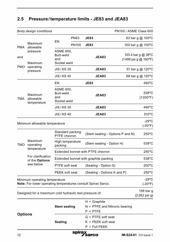
2.5 Pressure / temperature limits - JE83 and JEA83
Body design conditions PN100 / ASME Class 600
PMA
and
PMO
Maximum allowable pressure
Maximum operating pressure
ENPN63 JE83 63 bar g @ 100°C
PN100 JE83 100 bar g @ 100°C
ASME 600, Butt-weld and Socket weld
JEA83 103.4 bar g @ 38°C (1 499 psi g @ 100°F)
JIS / KS 30 JEA83 51 bar g @ 120°C
JIS / KS 40 JEA83 68 bar g @ 120°C
TMAMaximum allowable temperature
EN JE83 490°C
ASME 600, Butt-weld and Socket weld
JEA83 538°C (1 000°F)
JIS / KS 30 JEA83 490°C
JIS / KS 40 JEA83 510°C
Minimum allowable temperature-29°C
(-20°F)
TMOMaximum operating temperature
For clarification of the Options see below
Standard packing PTFE chevron (Stem sealing - Options P and N) 250°C
High temperature packing (Stem sealing - Option H) 538°C
Extended bonnet with PTFE chevron 250°C
Extended bonnet with graphite packing 538°C
PTFE soft seat (Seating - Option G) 200°C
PEEK soft seat (Seating - Options K and P) 250°C
Minimum operating temperature Note: For lower operating temperatures consult Spirax Sarco.
-29°C (-20°F)
Designed for a maximum cold hydraulic test pressure of: 156 bar g
(2 262 psi g)
Options
Stem sealingH = GraphiteN = PTFE and Nitronic bearingP = PTFE
SeatingG = PTFE soft seat K = PEEK soft seatP = Full PEEK
IM-S24-61 CH Issue 1 13
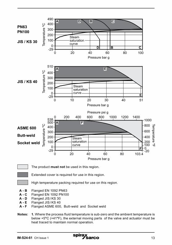
The product must not be used in this region.
Extended cover is required for use in this region.
High temperature packing required for use on this region.
A - B Flanged EN 1092 PN63 A - C Flanged EN 1092 PN100 A - D Flanged JIS / KS 30 A - E Flanged JIS / KS 40 A - F Flanged ASME 600, Butt-weld and Socket weld
Notes: 1. Where the process fluid temperature is sub-zero and the ambient temperature is below +5°C (+41°F), the external moving parts of the valve and actuator must be heat traced to maintain normal operation.
0
JIS / KS 40
Pressure bar g
ASME 600 Butt-weld Socket weld
Pressure bar g
PN63PN100
JIS / KS 30
Pressure bar g
Tem
pera
ture
°CTe
mpe
ratu
re °C
Tem
pera
ture
°C
Steamsaturationcurve
Steamsaturationcurve
Steamsaturationcurve
D B C
F
Pressure psi g
Temperature °F
A D B C
A E
E
A F
IM-S24-61 CH Issue 114
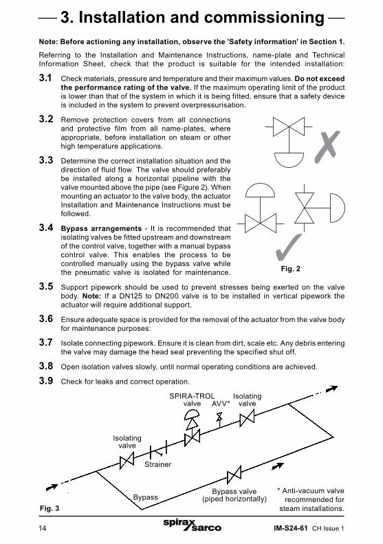
Note: Before actioning any installation, observe the 'Safety information' in Section 1. Referring to the Installation and Maintenance Instructions, name-plate and Technical Information Sheet, check that the product is suitable for the intended installation: 3.1 Check materials, pressure and temperature and their maximum values. Do not exceed
the performance rating of the valve. If the maximum operating limit of the product is lower than that of the system in which it is being fitted, ensure that a safety device is included in the system to prevent overpressurisation.
3.2 Remove protection covers from all connections and protective film from all name-plates, where appropriate, before installation on steam or other high temperature applications.
3.3 Determine the correct installation situation and the direction of fluid flow. The valve should preferably be installed along a horizontal pipeline with the valve mounted above the pipe (see Figure 2). When mounting an actuator to the valve body, the actuator Installation and Maintenance Instructions must be followed.
3.4 Bypass arrangements - It is recommended that isolating valves be fitted upstream and downstream of the control valve, together with a manual bypass control valve. This enables the process to be controlled manually using the bypass valve while the pneumatic valve is isolated for maintenance.
3.5 Support pipework should be used to prevent stresses being exerted on the valve body. Note: If a DN125 to DN200 valve is to be installed in vertical pipework the actuator will require additional support. 3.6 Ensure adequate space is provided for the removal of the actuator from the valve body
for maintenance purposes: 3.7 Isolate connecting pipework. Ensure it is clean from dirt, scale etc. Any debris entering
the valve may damage the head seal preventing the specified shut off. 3.8 Open isolation valves slowly, until normal operating conditions are achieved. 3.9 Check for leaks and correct operation.
3. Installation and commissioning
Isolatingvalve
Strainer
Bypass
SPIRA-TROL valve
Isolatingvalve
Bypass valve(piped horizontally)
AVV*
* Anti-vacuum valve recommended for
steam installations.Fig. 3
Fig. 23
7

IM-S24-61 CH Issue 1 15
4.1 GeneralValve parts are subject to normal wear and must be inspected and replaced as necessary. Inspection and maintenance frequency depends on the severity of the service conditions. This section provides instructions on replacement packing, stem, plug and seat and bellows. All maintenance operations can be performed with the valve body in the line.
AnnuallyThe valve should be inspected for wear and tear replacing any worn or damaged parts such as valve plug and stem, valve seat and gland seals, refer to Section 6 'Spare parts'.
Note 1: High temperature graphite packed seals are subject to wear during normal operation. We therefore recommend the graphite packing be replaced during this routine inspection to prevent premature failure of the packing during normal operation.
Note 2: It is recommended that all soft seals and gaskets be replaced whenever the valve is disassembled.
New torque values with lubrication:The following new torque values should be used with lubricated nuts / bolts:
Table 1 Recommended tightening torques - Control valve sizes DN15 to DN100
SPIRA-TROLvalve size
Torque (N m)JE / JEA
DN15 - DN25 100
DN32 - DN50 130
DN65 - DN80 130
DN100 130
Note: Before actioning any installation, observe the 'Safety information' in Section 1.
4. MaintenanceDN15 to DN100
Warning for all stainless steel valvesThe 316 type stainless steel used in the construction of these products particularly for screwed or close fitting parts, is very susceptible to galling or cold welding. This is an inherent characterisitic of this type of material and great care should therefore be taken when dismantling or reassembling.If the application permits, it is recommended that a light smear of a PTFE based grease is applied to any mating parts before reassembly.
1 3
4 2
Fig. 4
DN15 - DN50 bonnet tightening sequence
DN65 - DN100 bonnet tightening sequence
1
2
3
4
5
6

IM-S24-61 CH Issue 116
18
4.2 Removal of valve bonnetNote: This procedure is necessary before carrying out any of the maintenance procedures detailed below:- Ensure that the valve is depressurised and clear of media and isolate it both upstream and downstream.- Caution: care should be taken when disassembling the valve in case of residual pressure being trapped between the isolation points.- Remove the actuator from the valve. Refer to the Installation and Maintenance Instructions covering Spirax Sarco actuators.- Unscrew the stuffing box nuts (18).- Undo and remove the bonnet nuts (27).- Remove the bonnet (2) and plug and stem assembly (8).- Remove and discard the body gasket.
Fig. 5
8 188
PTFE Graphite
Fig. 6
27
22 2
27
4.3 Replacement of PTFE gland packings- Remove the lock-nut (3), stuffing box nuts, gland flange and gland follower (18), 'O' rings (15 and 17) and replace with new items. The use of silicone grease on the
'O' rings is recommended.- Withdraw the gland components and discard (9, 10, 12 and 14).- Clean the gland cavity and fit new gland components in the order
shown in Figure 7. Note that the lower bearing must be fitted with the radiused edge downwards. When fitting the chevron seals they should be inserted with correct orientation, one at a time to ease the assembly process - See the adjacent illustration:
3 3
15
17
Correct orientation of the chevronseals
IM-S24-61 CH Issue 1 17
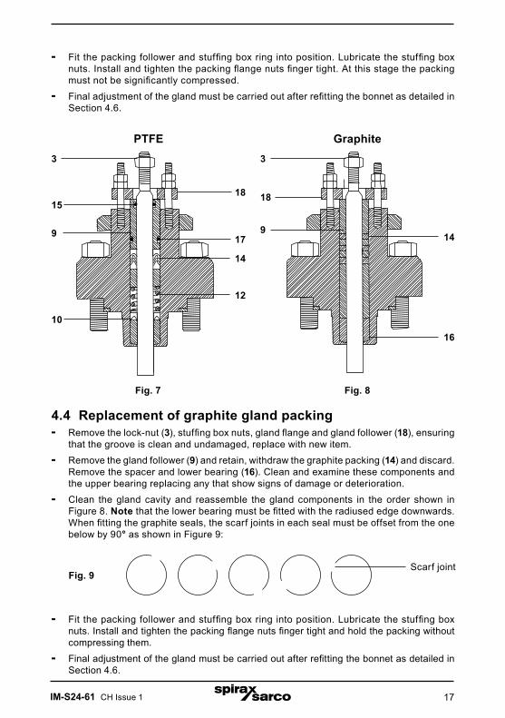
- Fit the packing follower and stuffing box ring into position. Lubricate the stuffing box nuts. Install and tighten the packing flange nuts finger tight. At this stage the packing must not be significantly compressed.
- Final adjustment of the gland must be carried out after refitting the bonnet as detailed in Section 4.6.
Fig. 7
3
18
14
12
3
18
14
PTFE Graphite
179
15
Fig. 8
4.4 Replacement of graphite gland packing- Remove the lock-nut (3), stuffing box nuts, gland flange and gland follower (18), ensuring
that the groove is clean and undamaged, replace with new item.- Remove the gland follower (9) and retain, withdraw the graphite packing (14) and discard.
Remove the spacer and lower bearing (16). Clean and examine these components and the upper bearing replacing any that show signs of damage or deterioration.
- Clean the gland cavity and reassemble the gland components in the order shown in Figure 8. Note that the lower bearing must be fitted with the radiused edge downwards. When fitting the graphite seals, the scarf joints in each seal must be offset from the one below by 90° as shown in Figure 9:
10
9
16
Scarf jointFig. 9
- Fit the packing follower and stuffing box ring into position. Lubricate the stuffing box nuts. Install and tighten the packing flange nuts finger tight and hold the packing without compressing them.
- Final adjustment of the gland must be carried out after refitting the bonnet as detailed in Section 4.6.
IM-S24-61 CH Issue 118
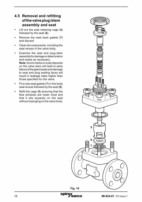
4.5 Removal and refitting of the valve plug /stem assembly and seat- Lift out the seat retaining cage (5)
followed by the seat (6).- Remove the seat back gasket (7)
and discard.- Clean all components, including the
seat recess in the valve body.- Examine the seat and plug / stem
assembly for damage or deterioration and renew as necessary.
Note: Score marks or scaly deposits on the valve stem will lead to early failure of the gland seals and damage to seat and plug sealing faces will result in leakage rates higher than those specified for the valve.
- Fit a new seat gasket (7) in the body seat recess followed by the seat (6).
- Refit the cage (5) ensuring that the flow windows are lower most and that it sits squarely on the seat without impinging on the valve body.
Fig. 10
5
6
7
IM-S24-61 CH Issue 1 19
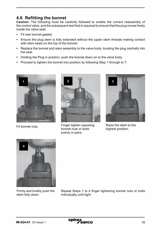
4.6 Refitting the bonnetCaution: The following must be carefully followed to enable the correct reassembly of the control valve, and the subsequent test that is required to ensure that the plug moves freely inside the valve seat:- Fit new bonnet gasket.- Ensure the plug stem is fully extended without the upper stem threads making contact
with stem seals on the top of the bonnet.- Replace the bonnet and stem assembly to the valve body, locating the plug centrally into
the seat. - Holding the Plug in position, push the bonnet down on to the valve body.- Proceed to tighten the bonnet into position by following Step 1 through to 7:
Repeat Steps 1 to 4 finger tightening bonnet nuts or bolts individually until tight.
Fit bonnet nuts.
1
Finger tighten opposing bonnet nuts or bolts evenly in pairs.
2 3
4
Raise the stem to the highest position.
Firmly and briskly push the stem fully down.
IM-S24-61 CH Issue 120
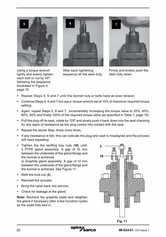
- Repeat Steps 5, 6 and 7 until the bonnet nuts or bolts have an even tension.
- Continue Steps 5, 6 and 7 but use a torque wrench set at 10% of maximum required torque setting.
- Again, repeat Steps 5, 6 and 7, incrementally increasing the torque value to 20%, 40%, 60%, 80% and finally 100% of the required torque value (as specified in Table 1, page 15).
- Pull the plug off its seat, rotate by 120° and slowly push it back down into the seat checking for any signs of resistance as the plug comes into contact with the seat.
- Repeat the above Step, three more times.
- If any resistance is felt, this can indicate the plug and seat is misaligned and the process will need repeating.
Fig. 11
5 6 7
Using a torque wrench lightly and evenly tighten each bolt or nut by 45°, following the sequence illustrated in Figure 4, page 15.
After each tightening sequence lift the stem fully.
Firmly and briskly push the stem fully down.
18
- Tighten the the stuffing box nuts (18) until: i) PTFE gland assembly: A gap of 10 mm
between the underside of the gland flange and the bonnet is achieved.
ii) Graphite gland assembly: A gap of 12 mm between the underside of the gland flange and the bonnet is achieved. See Figure 11.
- Refit the lock-nut (3).
- Reinstall the actuator.
- Bring the valve back into service.
- Check for leakage at the gland.
Note: Recheck the graphite seals and retighten the gland if necessary after a few hundred cycles as the seals fully bed in.
3

IM-S24-61 CH Issue 1 21
Note: Before actioning any installation, observe the 'Safety information' in Section 1.
5. MaintenanceDN125 to DN200
5.1 GeneralValve parts are subject to normal wear and must be inspected and replaced as necessary. Inspection and maintenance frequency depends on the severity of the service conditions. This Section provides instructions on the replacement of the packing, stem, plug and seat. All maintenance operations can be performed with the valve body in the line.Note: It is recommended that all soft seals and gaskets are replaced whenever the valve is disassembled.
AnnuallyThe valve should be inspected for wear and tear replacing any worn or damaged parts such as valve plug and stem, valve seat and gland seals, refer to Section 6 'Spare parts'.
Note 1: High temperature graphite packed seals are subject to wear during normal operation. We therefore recommend the graphite packing be replaced during this routine inspection to prevent premature failure of the packing during normal operation.
Note 2: It is recommended that all soft seals and gaskets be replaced whenever the valve is disassembled.
Table 2 Recommended tightening torques - Control valve sizes DN125 to DN200
DN125 DN150 DN200JE and JEA 203 N m 245 N m 365 N m
�
� �
�
��������������Fig. 12 DN125 to DN200
IM-S24-61 CH Issue 122
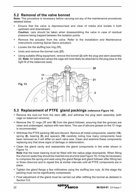
5.2 Removal of the valve bonnetNote: This procedure is necessary before carrying out any of the maintenance procedures detailed below:- Ensure that the valve is depressurised and clear of media and isolate it both upstream and downstream.
Caution: care should be taken when disassembling the valve in case of residual pressure being trapped between the isolation points.
- Remove the actuator from the valve. Refer to the Installation and Maintenance Instructions covering Spirax Sarco actuators.
- Loosen the the stuffing box ring (11).- Undo and remove the bonnet nuts (21).- Using suitable lifting equipment, remove the bonnet (2) with the plug and stem assembly
(3). Note: for balanced valves the cage will most likely be attached to the plug (due to the tight fit of the balanced seal).
Fig. 13
5.3 Replacement of PTFE gland packings (reference Figure 14)- Remove the lock-nut from the stem (20), and withdraw the plug stem assembly (with
cage on balanced versions).- Remove the 'O' rings (17 and 18) from the gland follower, ensuring that the grooves are
clean and undamaged, replace with new items. The use of silicone grease on the 'O' rings is recommended.
- Withdraw the PTFE packing (12) and discard. Remove all metal components, washer (14), spring (8), bearing (9) and spacers (10) carefully noting how many components have been removed as it will differ on each valve size. Clean and examine these components replacing any that show signs of damage or deterioration.
- Clean the gland cavity and reassemble the gland components in the order shown in Figure 13.
Note that the lower bearing must be fitted with the radius edge downwards. When fitting the chevron seals they should be inserted one at a time (see Figure 15). It may be necessary to compress the spring and seat using the gland flange and gland follower after fitting two or three chevrons and to repeat this at similar intervals until all PTFE components are in place.
- Tighten the gland flange a few millimetres using the stuffing box nuts. At this stage the packing must not be significantly compressed.
- Final adjustment of the gland must be carried out after refitting the bonnet as detailed in Section 5.6.
113
20
21
2
IM-S24-61 CH Issue 1 23
Fig. 14
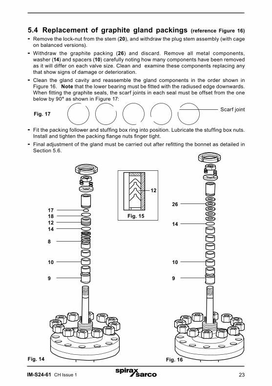
5.4 Replacement of graphite gland packings (reference Figure 16)- Remove the lock-nut from the stem (20), and withdraw the plug stem assembly (with cage
on balanced versions).- Withdraw the graphite packing (26) and discard. Remove all metal components, washer (14) and spacers (10) carefully noting how many components have been removed
as it will differ on each valve size. Clean and examine these components replacing any that show signs of damage or deterioration.
- Clean the gland cavity and reassemble the gland components in the order shown in Figure 16. Note that the lower bearing must be fitted with the radiused edge downwards. When fitting the graphite seals, the scarf joints in each seal must be offset from the one below by 90° as shown in Figure 17:
- Fit the packing follower and stuffing box ring into position. Lubricate the stuffing box nuts. Install and tighten the packing flange nuts finger tight.
- Final adjustment of the gland must be carried out after refitting the bonnet as detailed in Section 5.6.
Scarf joint
Fig. 16
Fig. 17
Fig. 15
12
9
14
171812
8
10
9
14
26
10

IM-S24-61 CH Issue 124
5.5 Procedure for removal and refitting of valve plug /stem assembly and seat5.5.1 Unbalanced valves- Using lifting equipment as appropriate, withdraw the plug / stem assembly (3).- Lift out the cage (4) followed by the seat (6).- Remove the seat back gasket (16) and discard.- Clean all the components, including the seat recess in the valve body.- Examine the seat and plug / stem assembly for damage or deterioration and renew as
necessary. Note: Score marks or scaly deposits on the valve stem will lead to early failure of the gland
seals and damage to seat and plug sealing faces will result in leakage rates higher than those specified for the valve.
- Fit a new seat gasket (16) in the body seat recess followed by the seat (6).- Refit the cage (4) ensuring that the flow windows are lower most and that it sits squarely
on the seat without impinging on the valve body.- Lower the plug / stem assembly squarely onto the seat ring ensuring that the stem is left
vertical.
5.5.2 Balanced valves- Using lifting equipment as appropriate, withdraw the plug / stem assembly (3) taking care
not to let the cage fall back into the valve body.- Remove and discard the upper cage seal (19). - Remove and discard the balance seal (31).- Lift out the seat (6).- Remove the seat gasket (16) and discard.- Clean all the components, including the seat recess in the valve body.- Examine the cage, seat and plug / stem assembly for damage or deterioration and renew
as necessary. Note: Score marks or scaly deposits on the cage internal surface or valve stem will lead
to early failure of the seals and damage to the seat and plug sealing faces will result in leakage rates higher than those specified for the valve.
- Fit a new seat gasket (16) in the body seat recess followed by the seat (6).- Refit the cage (4) ensuring that the flow windows are lower most and that it sits squarely
on the seat without impinging on the valve body.- Fit a new balance seal (31) into the plug groove.- Refit the plug / stem into the cage ensuring that the balanced seal is not damaged during
this process - Note: a light smear of silicone grease on the inner surface of the cage will aid fitting. The plug / stem assembly should easily move up and down in the cage, using moderate hand force, until it is located in the seat.
- Fit a new upper cage seal (19).

IM-S24-61 CH Issue 1 25
Fig. 18 Balanced
3
19
4
616
31
Fig. 19
15
IM-S24-61 CH Issue 126
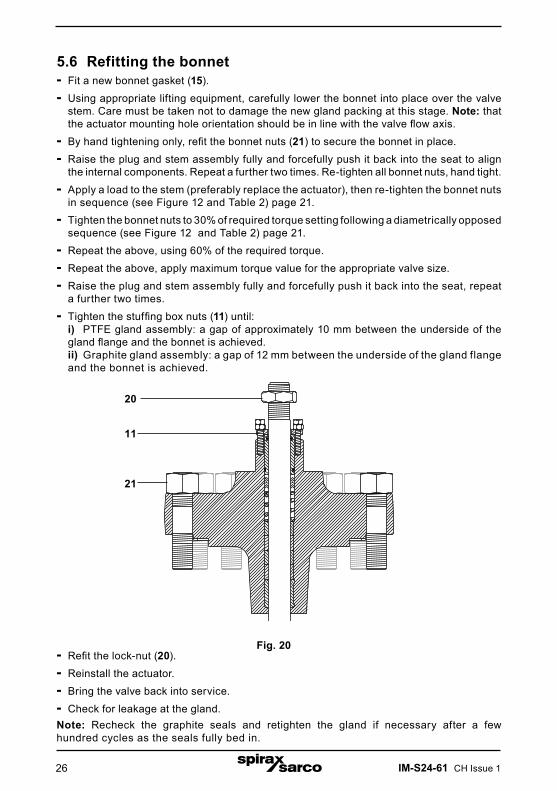
5.6 Refitting the bonnet- Fit a new bonnet gasket (15).- Using appropriate lifting equipment, carefully lower the bonnet into place over the valve
stem. Care must be taken not to damage the new gland packing at this stage. Note: that the actuator mounting hole orientation should be in line with the valve flow axis.
- By hand tightening only, refit the bonnet nuts (21) to secure the bonnet in place.- Raise the plug and stem assembly fully and forcefully push it back into the seat to align
the internal components. Repeat a further two times. Re-tighten all bonnet nuts, hand tight.- Apply a load to the stem (preferably replace the actuator), then re-tighten the bonnet nuts
in sequence (see Figure 12 and Table 2) page 21.- Tighten the bonnet nuts to 30% of required torque setting following a diametrically opposed
sequence (see Figure 12 and Table 2) page 21.- Repeat the above, using 60% of the required torque.- Repeat the above, apply maximum torque value for the appropriate valve size.- Raise the plug and stem assembly fully and forcefully push it back into the seat, repeat
a further two times.- Tighten the stuffing box nuts (11) until: i) PTFE gland assembly: a gap of approximately 10 mm between the underside of the
gland flange and the bonnet is achieved. ii) Graphite gland assembly: a gap of 12 mm between the underside of the gland flange
and the bonnet is achieved.
Fig. 20- Refit the lock-nut (20).- Reinstall the actuator.- Bring the valve back into service.- Check for leakage at the gland.Note: Recheck the graphite seals and retighten the gland if necessary after a few hundred cycles as the seals fully bed in.
20
11
21
IM-S24-61 CH Issue 1 27
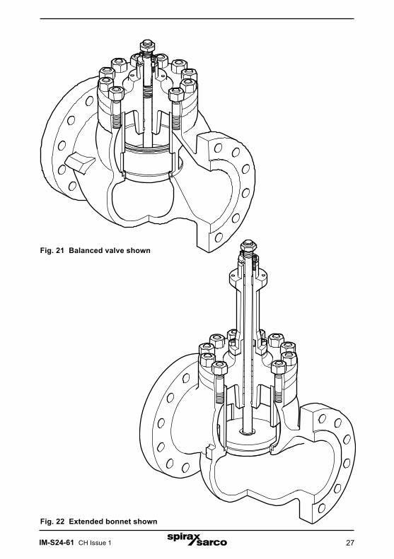
Fig. 21 Balanced valve shown
Fig. 22 Extended bonnet shown
IM-S24-61 CH Issue 128
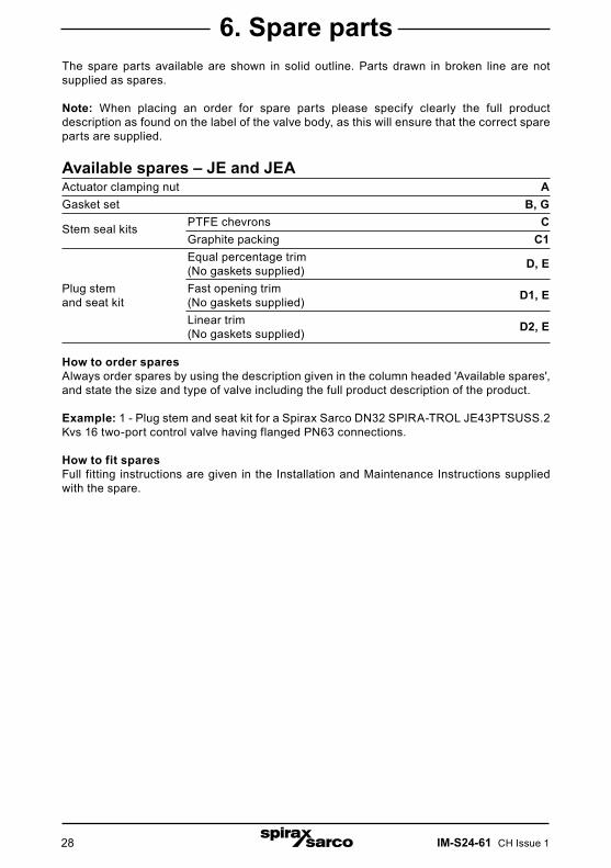
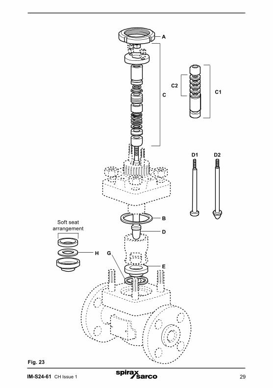
6. Spare partsThe spare parts available are shown in solid outline. Parts drawn in broken line are not supplied as spares.
Note: When placing an order for spare parts please specify clearly the full product description as found on the label of the valve body, as this will ensure that the correct spare parts are supplied.
Available spares – JE and JEAActuator clamping nut AGasket set B, G
Stem seal kits PTFE chevrons C Graphite packing C1 Equal percentage trim (No gaskets supplied) D, E
Plug stem Fast opening trimand seat kit (No gaskets supplied) D1, E
Linear trim (No gaskets supplied) D2, E
How to order sparesAlways order spares by using the description given in the column headed 'Available spares', and state the size and type of valve including the full product description of the product.
Example: 1 - Plug stem and seat kit for a Spirax Sarco DN32 SPIRA-TROL JE43PTSUSS.2 Kvs 16 two-port control valve having flanged PN63 connections.
How to fit sparesFull fitting instructions are given in the Installation and Maintenance Instructions supplied with the spare.
IM-S24-61 CH Issue 1 29
Fig. 23
C1C
D1 D2
A
H
C2
Soft seat arrangement
B
D
E
G

IM-S24-61 CH Issue 130

IM-S24-61 CH Issue 1 31

IM-S24-61 CH Issue 132