SPH & BPH - Cemline Corporation
41
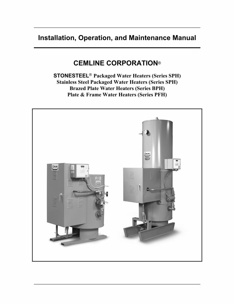
Installation, Operation, and Maintenance Manual CEMLINE CORPORATION ® STONESTEEL Packaged Water Heaters (Series SPH) Stainless Steel Packaged Water Heaters (Series SPH) Brazed Plate Water Heaters (Series BPH) Plate & Frame Water Heaters (Series PFH)
Transcript of SPH & BPH - Cemline Corporation
Installation, Operation, and Maintenance Manual
CEMLINE CORPORATION®
STONESTEEL Packaged Water Heaters (Series SPH) Stainless Steel Packaged Water Heaters (Series SPH)
Brazed Plate Water Heaters (Series BPH) Plate & Frame Water Heaters (Series PFH)

I
Table of Contents Section Page Disclaimers ..........................................................................................................................1 General Information.............................................................................................................2 Energy and Power Sources ......................................................................................2 Construction.............................................................................................................3 Advantages and Benefits of CEMLINE® Packaged Water Heaters...................................5 Warranty Information ..............................................................................................5 Contact Information .................................................................................................5 General Notes and Warnings ...............................................................................................6 Notes ........................................................................................................................6 Warnings ..................................................................................................................7 Product Features and Specifications ....................................................................................9 Installation .........................................................................................................................10 Transporting and Unpacking the Unit ...................................................................10 Examining the Unit ................................................................................................10 Mounting the Unit..................................................................................................11 Familiarization with the Unit and Components .....................................................11 Connecting the Cold Water Source and Hot Water Outlet ....................................12 Connecting the Energy Source ..............................................................................13 Connecting the Boiler Water / High Temperature Water Return Lines or the Steam Condensate Line ..............13 Piping the Relief Valves to Drain ..........................................................................14 Piping the Water Dump Valve to Drain.................................................................15 Connecting the Circulation Pump and Electrically Activated Controls ................15 Completing Installation..........................................................................................15 Operation ...........................................................................................................................16 Startup Procedures .................................................................................................16 Shutdown Procedures ............................................................................................17 Parts List ............................................................................................................................19 Replaceable Parts List............................................................................................19 Suggested Spare Parts ............................................................................................19 Ordering Information .............................................................................................20 Inspection...........................................................................................................................21

II
Troubleshooting .................................................................................................................22 Probable Cause and Remedy .................................................................................22 Maintenance.......................................................................................................................25 Circulating Pump - Inspection and Replacement ..................................................25 Circulating Pump Shutoff Valves - Replacement..................................................26 Power Connections - Rewiring ..............................................................................27 Brazed Heat Exchanger or Plate Heat Exchanger and Gaskets - Inspection and Replacement ........................................................27 Inlet, Outlet, and Water Return / Condensate Line and Manual Shutoff Valves - Replacement ................................................................29 Pressure Gauge (Energy Source) - Replacement ...................................................30 Pressure Gauge (Water) - Replacement.................................................................30 Pressure Relief Valve (Tank) - Replacement ........................................................31 Single Solenoid Safety System - Inspection and Replacement .............................32 Water Dump Valve - Inspection and Replacement................................................33 Strainers - Inspection and Replacement.................................................................34 Temperature Control Valve - Inspection and Replacement...................................34 Thermometer - Replacement..................................................................................36 Traps (Main and Auxiliary) - Replacement (Steam Systems Only) ......................36
2010 Cemline Corporation. All Rights Reserved. All trademarks in this manual are property of Cemline Corporation, unless otherwise noted or in any other way set forth as a third party rights. Unauthorized use of these trademarks, as well as the materials presented on this site, is expressly prohibited and constitutes a violation of the intellectual property rights of Cemline Corporation.
1
Disclaimers This Installation, Operation, and Maintenance Manual is intended to be as complete and up to date as possible. It covers the installation, operation, and maintenance procedures for CEMLINE CORPORATION's SPH Series Packaged Water Heaters. CEMLINE reserves the right to update this manual and other product information concerning installation, operation, and / or maintenance, at any time and without obligation to notify product owners of such changes. CEMLINE is not responsible for inaccuracies in specifications, procedures, and / or the content of other product literature supplied by the manufacturers of components used in CEMLINE Packaged Water Heaters (i.e.: pumps, valves, temperature controls, gauges, etc.). CEMLINE strives to use only the highest quality components in building the SPH Series Packaged Water Heaters. However, CEMLINE has no direct control over components manufacture, or their consistent quality. CEMLINE is not responsible for injury to personnel or product damage due to the improper installation, operation, and / or maintenance of CEMLINE Packaged Water Heaters. All installation, operation, and maintenance procedures should only be performed by trained / certified personnel. All personnel performing these procedures should completely and carefully read and understand all supplied materials before attempting the procedures. All personnel should pay strict attention to all Notes, Cautions, and Warnings that appear within the procedures detailed in this manual. CEMLINE welcomes user input as to suggestions for product or manual improvement.

2
General Information This Installation, Operation, and Maintenance Manual is designed as a procedural guide for all CEMLINE CORPORATION STONESTEEL , Stainless Steel Packaged Water Heaters, Brazed Plate Water Heaters, and Plate & Frame Water Heaters. Covered in this manual are: Series SPH - STONESTEEL Storage Plate Water Heaters;
Series SPH - Stainless Steel Storage Plate Water Heaters;
Series BPH - Brazed Plate Water Heaters;
Series PFH - Plate & Frame Water Heaters.
Energy and Power Sources
For Heating Water
All CEMLINE SPH, BPH, and PFH Packaged Water Heaters can be configured and manufactured to use one (1) of three (3) possible energy sources for heating water: boiler water; high temperature water; or steam; Note: Most CEMLINE SPH, BPH, PFH Packaged Water Heaters use boiler
water as the energy source for heating water. Therefore, procedures detailed in this manual will be geared towards the installation, operation, and maintenance of boiler water powered units. When procedures differ substantially for the installation, operation, and maintenance of units powered by either high temperature water or steam, notes will be included giving specific instructions for those units.
The following table lists the range of acceptable pressures at the inlet for each energy source.
Energy Source Minimum Pressure
(PSI) Maximum Pressure
(PSI) Boiler Water 0 150 High Temperature Water Unknown 400 Steam 0 150

3
Note: Consult the design specifications for each unit, as well as the nameplate attached to the exterior of the tank and individual specification tags on pressure related components and controls, for design and maximum pressure for the unit.
For Circulating Pumps and Controls
CEMLINE Packaged Water Heaters can be equipped with a circulating pump to assist in the even heating of the water, and electrically activated controls to regulate pressure and temperature. Pumps and electric controls used, depending on individual design specifications, can range in power requirements from 120 volt single phase to 480 volt three phase. Consult the individual design specifications for the unit and identification plates attached to the pump and controls for the exact requirements.
Construction All CEMLINE Packaged Water Heaters are constructed from superior materials and utilize only the highest quality components. Each water heater vessel meets or exceeds all applicable American Society of Mechanical Engineers (A.S.M.E.) Code regulations.
Tanks and Linings
Depending on the series purchased, CEMLINE Packaged Water Heaters are equipped with either STONESTEEL or Stainless Steel tanks, ranging in capacity from 3 to 6,080 gallons. Each tank is designed and constructed in strict accordance with the latest A.S.M.E. Code regulations, stamped in accordance with the applicable section of the A.S.M.E. Code, and accompanied by the applicable certificates. Each tank is manufactured using pressure vessel quality plate and welded by certified welders. All tanks are registered with the National Board of Boiler and Pressure Vessel Inspectors. STONESTEEL tanks are lined with hydraulic cement, using the exclusive CEMLINE patented process. This time proven process prevents rust and corrosion, common to metal tanks, and helps guarantee exceptionally long life. Each CEMLINE Packaged Water Heater is equipped with an A.S.M.E. approved relief valve and an external drain, providing a means to remove accumulated sediment.
Water Heater Jackets
The water heater jackets used for all CEMLINE Packaged Water Heaters are constructed of twenty (20) gauge metal and professionally painted with a superior quality enamel paint. This procedure increases corrosion resistance and provides an attractive, easy to maintain surface.

4
A nameplate, mounted to the jacket, bears the model and serial numbers of the unit. These numbers should be included in all correspondence regarding the unit.
Insulation
All CEMLINE Packaged Water Heaters contain a three inch (3") layer of insulation between the tank and jacket. Depending on the Series, the insulation consists of either fiberglass or foam that conforms to the latest American Society of Heating, Refrigeration, and Air Conditioning Engineers (A.S.H.R.A.E.) Standards for commercial water heaters.
Plate Heat Exchanger Coils
The brazed plate or plate and frame heat exchangers are manufactured from 316L stainless steel. Brazed plate heat exchangers are vacuum-brazed with a copper or nickel based filler. Plate and frame heat exchangers are assembled with fixed plates, carrier bars, that are gasketed and compressed together in a steel frame.
Components
All other components included in CEMLINE Packaged Water Heaters have been specifically selected to meet the individual design specifications of each unit. Each component is judged to be of highest quality to provide long life and superior performance.
Component Piping and Joints
All CEMLINE tanks are manufactured with stainless steel threaded openings. All component piping and joints are manufactured from non-corroding (copper, brass, or stainless) piping to insure that water never contacts steel, which is subject to corrosion.

5
Advantages and Benefits of CEMLINE Packaged Water Heaters
STONESTEEL or Stainless Steel tanks offer years of reliable, trouble free service. High quality design, construction, and components. Compact size is ideal for both new installations and as a replacement for an existing unit. Built and "Packaged" to meet exact customer design specifications. CEMLINE "Packaging" helps keep installation time to a minimum. Offers a wide range of configurations and capacities. Warranty Information STONESTEEL tanks are warranted for ten (10) years from date of purchase. Stainless Steel tanks are warranted for five (5) years from date of purchase. All other components used in CEMLINE Packaged Water Heaters are warranted for one (1) year from startup or eighteen (18) months from date of purchase, whichever comes first. Contact Information For information concerning warranty information, or for questions pertaining to the installation, operation, or maintenance of CEMLINE Packaged Water Heaters, contact: CEMLINE CORPORATION P. O. Box 55 Cheswick, PA 15024 USA Phone: (724) 274-5430 USA Fax: (724) 274-5448 www.cemline.com To order replacement parts, contact CEMLINE CORPORATION at the address listed above, or call toll free: USA Phone: (800) 245-6268 Please include the model and serial number of the unit for which the parts are being ordered. If ordering by phone, please have this information readily available.

6
General Notes and Warnings Notes
This manual is intended to cover installation, operation, and maintenance procedures for CEMLINE CORPORATION SPH Series Packaged Water Heaters. Since each unit is built to meet customer specifications, instructions may seem general in nature at times. Where procedures differ substantially between the brazed plate or plate & frame style heat exchangers; or between boiler water, high temperature water, or steam as the energy source for water heating; specific notes will be given.
If questions are not answered by this manual, or if specific installation, operation,
and / or maintenance procedures are not clearly understood, contact CEMLINE for clarification before proceeding.
All installation, operation, and maintenance procedures should be performed by
experienced, trained, and certified personnel only. Personnel should be trained in correct plumbing and electrical procedures and methods, and should be experienced in working with steam and boiler water / high temperature water systems.
CEMLINE Packaged Water Heaters are designed for indoor use only, unless
otherwise required by design specifications. Each unit requires at least two feet (2') of clearance around and above the unit. It should be located on a level surface (no more than one-half degree [½º] of slope), capable of supporting the total weight of the unit when filled to capacity.
The unit should be mounted to the floor following applicable architectural and
local code requirements for the specific installation site. Series SPH units should be mounted on house keeping pads, providing a minimum of one inch (1") clearance between the floor and the unit.
In areas prone to seismic activity, it is recommended that the unit be mounted to
the floor according to recommended procedures for the site / location to make the units less susceptible to seismic damage.
The high quality enamel paint, applied to the jacket of the unit, will provide years
of protection against corrosion. If it is necessary to clean the outside of the unit, a mild cleaning agent should be used that will not damage the paint.
Inspection procedures, troubleshooting, and periodic maintenance, as well as
suggested intervals, are detailed on pages 21 to 36 of this manual.
7
CEMLINE Packaged Water Heaters are available in a wide range of operating pressures and temperatures. For the specific ranges for your unit, refer to the design specifications and accompanying literature supplied with the unit.
If the unit is damaged during installation, operation, or maintenance, follow the
following steps. 1. Turn off the power to the unit. 2. Turn off the inlet boiler water / high temperature water / steam inlet
valve(s).
3. Turn off the boiler water / high temperature return valves or condensate outlet valves.
4. Turn off cold water inlet valves and hot water outlet valves. 5. Contact in-house maintenance personnel or CEMLINE CORPORATION
for instructions.
For all piping connections, the use and / or type of joint compound or sealer on the joints should be determined by referring to local codes, accepted standards, and / or the requirements of the installing contractor.
Warnings As with any piece of equipment that utilizes steam, boiler water, or high temperature water under pressure, as well as electricity, the potential exists for severe personal injury if proper installation, operation, and maintenance procedures are not followed. Listed below are specific warnings pertaining to CEMLINE Packaged Water Heaters. In addition, throughout this manual, warnings are restated when procedures are described pertaining to areas of potential danger. All warnings should be carefully read and understood. All precautions contained in the warnings should be carefully followed to reduce the chance of injury. Note: Throughout this manual, warnings will be denoted by the symbol . All documentation for each major component has been included with the unit. It is strongly recommended that each document be reviewed before attempting any installation, operation, or maintenance procedures. The documentation for each major component may also contain warnings and cautions. These warnings and cautions may be specific for the particular component, and therefore not covered in this general Installation, Operation, and Maintenance Manual. They should also be carefully reviewed before attempting installation, operation, or maintenance procedures.
8
Areas of potential danger: 1. all boiler water / high temperature water / steam lines, joints, valves, and
pressure regulators; 2. all hot water outlet lines, joints, valves, and pressure regulators; and 3. all power connections and cables.
Before attempting any installation, operation, or maintenance procedures pertaining to the unit:
1. assure that the incoming boiler water / high temperature water (or steam)
has been turned off at the manual shutoff valve; 2. if the unit has been in operation, allow the water in the heater and all
components and surfaces (incoming steam line, hot water outlet line, etc.) to cool before starting the procedure;
3. assure that all power has been shut off / disconnected before
attempting any procedures; and 4. assure that all incoming and outgoing water lines have been turned off at
the manual shutoff valves.
Boiler water, high temperature water, or steam present situations that can be very dangerous due to the fact they are under pressure and at very high temperatures. To avoid possible injury or death, use common sense and follow all accepted and recommended procedures when performing installation, operation, and maintenance procedures.
The combination of electricity and water can pose a very dangerous situation.
Assure that all power has been shut off / disconnected before attempting any installation or maintenance procedures.
9
Product Features and Specifications Congratulations on purchasing a CEMLINE CORPORATION Packaged Water Heater. The unit purchased will offer years of superior dependable service. CEMLINE Packaged Water Heaters, employing the brazed plate or plate and frame heat exchanger, are the most economical method of furnishing domestic hot water when boiler water are used as the energy source. All CEMLINE Water Heaters are "Packaged" and ready for installation. All components are sized, mounted, and piped prior to shipment. Each unit is built to exact customer design specifications and requires only connection to energy, water, and power sources to be ready for operation. The "Packaging" concept provides a compact size that is ideal for new installations or for use as replacement of existing water heaters. The compact size requires less space for installation, and makes moving the unit through doorways, work areas, etc., less of a problem. Each unit employs either a STONESTEEL or Stainless Steel tank, providing years of trouble free service. All components used in the unit are of highest quality and meet or exceed all customer design specifications and American Society of Mechanical Engineers (A.S.M.E.) Code regulations. Each water heater is accompanied by this Installation, Operation, and Maintenance Manual, a detailed Submittal sheet and C.A.D. drawing, as well as all documentation supplied by the manufacturer of each major component. If any of these documents are missing, contact either CEMLINE CORPORATION or your authorized sales representative.

10
Installation Transporting and Unpacking the Unit Each CEMLINE CORPORATION Packaged Water Heater is crated, as necessary, at the factory. The crating is designed to provide protection for the unit during transportation, and to provide a safe means by which to lift and move the unit with a fork lift or hand truck. On horizontal SPH units, lifting lugs are provided inside the jacket to provide a safe lifting position.
The unit should only be lifted at the areas indicated on the crate, or by the lifting lugs provided. Improper lifting of the unit may result in damage to the unit.
Location Requirements
CEMLINE Packaged Water Heaters are designed for indoor use only and require at least two feet (2') of clearance around and above the unit, unless otherwise required by the design specifications. The unit should be located on a level surface (no more than one-half degree [½º] of slope), capable of supporting the total weight of the unit when filled to capacity. Once the unit has been set in place, the crating should be carefully removed.
Examining the Unit After the unit has been set in place and uncrated, it should be carefully examined to assure that neither the main unit nor components have been damaged during shipping. If any evidence of damage is detected that could affect the safe operation of the unit, contact CEMLINE CORPORATION, or your authorized sales representative, to report the damage and to receive instructions on how to proceed. After the unit and all components have been inspected for damage, it is suggested that all pressure and temperature control components be checked to assure that they meet or exceed design specifications. This can be done by reviewing the design specifications (included with the unit) and the specification tags / plates attached to each component. If any discrepancy is found, contact CEMLINE CORPORATION, or your authorized sales representative, before proceeding with the installation.

11
Mounting the Unit The unit should be mounted to the floor, following applicable architectural / local code requirements, or accepted standards for the specific installation site and for the Series purchased. Note: Series SPH units should be mounted on house keeping pads, pro viding a minimum of one inch (1") clearance between the floor and the unit. In areas prone to seismic activity, it is recommended that the unit be mounted to the floor, according to recommended procedures for the site, to make the units less susceptible to seismic damage. Familiarization with the Unit and Components CEMLINE Packaged Water Heaters are designed to make installation a relatively simple procedure. Because the unit is "Packaged," after placing and mounting the unit, installation involves: 1. connecting the cold water source to the water inlet; 2. connecting the hot water outlet to the hot water feed line; 3. connecting the water return / condensate line and piping it to the recycling system; 4. piping the pressure relief valve to an acceptable drain; 5. connecting the energy source (boiler water, high temperature water, or steam) to the unit; and 6. wiring the applicable source of electricity (if the unit is packaged with a circulating pump or electrically activated pressure or temperature controls). Each unit is supplied with a Submittal sheet and C.A.D. drawing that indicates the location and specifications for each connection that must be made. In addition, the drawing will enable the installer(s) to determine the flow direction of both the water and energy source.

12
Connecting the Cold Water Source and Hot Water Outlet Note: Before making any connections of water inlet or outlet to the unit, assure that all piping is clean and free of foreign material or scale. This can usually be accomplished by "blowing out" the pipe. Any foreign material or scale entering the unit can adversely affect operation and performance.
Cold Water Source
The first step in the installation process is to connect the cold water source to the water inlet port. The exact location of this port for the specific unit, as well as inlet pipe diameter and thread size, can be determined from the C.A.D. drawing supplied with the Submittal sheet. A manual shutoff valve should be installed upstream on the cold water source as an isolation device. The shutoff valve should be in the closed position and remain so until the installation is complete.
Note: For all piping connections, the use and / or type of joint compound or sealer on the joint should be determined by referring to local codes, accepted practices, or the requirements of the installing contractor. If the cold water source is equipped with an in-line check valve or back flow preventer, a suitable expansion tank must be installed in the hot water outlet side of the system. See the supplied Submittal sheet and C.A.D. drawing, or contact CEMLINE CORPORATION for expansion tank specifications.
Hot Water Outlet
The next step in the installation process is to connect the hot water system piping to the hot water outlet port. The exact location of this port for the specific unit, as well as outlet pipe diameter and thread size, can be determined from the C.A.D. drawing supplied with the Submittal sheet. A manual shutoff valve should be installed downstream on the hot water outlet line as an isolation device in case the unit must be disconnected from the system. The shutoff valve should be in the closed position and remain so until the installation is complete.
13
Connecting the Energy Source (Boiler Water, High Temperature Water, or Steam)
Boiler water, high temperature water, or steam present situations that can be very dangerous because of the high temperatures and pressures. Use common sense and follow all accepted and recommended procedures when performing installation, operation, and maintenance procedures to avoid possible injury or death.
Assure that a manual shutoff valve is installed upstream in the boiler water, high temperature hot water, or steam line (energy source), and that it is functioning properly. If any doubt exists concerning the integrity of the shutoff valve, replace the valve before attempting installation. All energy source valves should be closed and remain closed throughout the installation process. Connect the energy source to the line(s) leading to the temperature control valve. The exact location of the temperature control valve for the specific unit, as well as energy source pipe diameter and thread size, can be determined from the C.A.D. drawing supplied with the Submittal sheet. Note: For all energy source piping connections, the use and / or type of joint compound or sealer on the joint should be determined by referring to local codes, accepted practices, or the requirements of the installing contractor. Connecting the Boiler Water Return / High Temperature Water Return Lines or the Steam Condensate Line
Boiler Water and High Temperature Water Return Line
After the boiler water or high temperature water has passed through the heat exchanger, and the heat has been extracted and transferred to the domestic water system, the water must return to the system. The water return line serves this purpose. The water return line should be connected to the unit at the return port. Unlike the steam condensate return line, the return lines for boiler and high temperature water do not have in-line condensate traps. The return port is normally located downstream from the heat exchanger. The exact location of this port for the specific unit, as well as the water return pipe diameter and thread size, can be determined from the C.A.D. drawing supplied with the Submittal sheet.
A manual shutoff valve should be installed downstream in the water return line to allow the unit to be isolated from the system. The water return shutoff valve will prevent back flow of boiler water or high temperature water if the line is disconnected.

14
Steam Condensate Return Line
As the heat is extracted from the steam and transferred to the water heating system, condensate will form. This condensate must have a means by which it can drain from the unit and return to the steam system. The condensate return line serves this purpose. The condensate return line should be connected to the unit at the condensate return port. The condensate port is normally located downstream from the main and auxiliary traps. The exact location of this port for the specific unit, as well as the condensate return pipe diameter and thread size, can be determined from the C.A.D. drawing supplied with the Submittal sheet. The condensate line should be piped back into the site's steam system for recycling. A manual shutoff valve should be installed downstream in the condensate return line to allow the unit to be isolated from the system. The condensate shutoff valve will prevent back flow of steam if the line is disconnected. Do not attempt to lift condensate with a float and thermostatic trap. Pipe
the condensate outlet from the main steam trap to a gravity drain or to a condensate pump.
Lifting condensate without the assistance of a condensate pump can cause
erratic temperature control, failure of the heat exchanger, damage to the control valve, or damage to the condensate trap. Any failure caused due to lifting of condensate without a condensate pump is not covered by the warranty.
Piping the Relief Valves to Drain All CEMLINE Packaged Water Heaters are equipped with pressure relief valve for the tank. Valve should be piped to a vent line leading to a suitable drain. Piping the pressure relief valves to suitable drains will prevent both water and heat damage to the unit, as well as reduce the risk of injury from released steam or water. The pipe must be of adequate size to properly handle the capacity of the relief valve and vent line. Check local codes to assure compliance. If a check valve has been installed on the inlet water line, thermal expansion may take place causing build up of excessive pressure when the water is being heated. This expansion will cause the relief valve to open, releasing hot water to the vent line.
Do not install a valve between the water heater relief valve and the vent. Doing so could cause serious injury or death if the pressure relief valve released and the manual valve was closed. This would cause excessive buildup of pressure in the water heater which could result in an explosion.
15
Piping the Water Dump Valve to Drain Some CEMLINE Packaged Water Heaters are furnished with a ¾” solenoid (water dump valve) which is connected to the vessel near or at the top of the unit. On these units the water dump valve will open at a set point normally higher than the limit temperature, and dump the hot water in the heater to drain. Be sure to pipe the outlet from this solenoid to drain.
Failure to pipe the dump valve to drain could cause a hazardous condition as well as flooding of the equipment room. Use common sense and follow all accepted and recommended procedures when performing installation, operation, and maintenance to avoid possible injury or death.
Connecting the Circulation Pump and Electrically Activated Controls CEMLINE CORPORATION Packaged Water Heaters are equipped with a circulation pump. If the unit being installed is so equipped, the correct power source(s) must be connected. The circulation pump must run all the time. Wire this pump to correctly sized disconnect switch per local code.
The combination of electricity and water can pose a very dangerous situation. Assure that all electric power has been turned off before attempting any installation or maintenance procedures.
Reference the wiring C.A.D. drawing that is included with the Submittal sheet, or the installation instructions contained in the Installation Manual for the component, for specific wiring instructions. Note: All power connection should be performed by trained, certified electricians. Completing Installation Installation of the CEMLINE Packaged Water Heater is now complete. All documentation supplied with the unit should be passed along to maintenance personnel for future reference.

16
Operation After all installation procedures have been completed, and all water, energy source joints, and power connections have been double checked, the unit is ready for operation. As a precaution, it is strongly suggested that the following startup and shutdown procedures be followed. Startup Procedures 1. Assure that all manual shutoff valves on water and energy source lines are closed. 2. Slowly open the manual shutoff valve on the cold water inlet line, checking to
assure that there are no leaks at the valve or any joints. Allow the tank to fill with water. As the tank is filling, hold the pressure relief valve open to allow air to bleed out of the tank. This will speed the filling process.
3. Adjust the operating temperature control to the desired operating temperature. See
the Submittal sheet and the operating temperature control component manual, included with the unit, for the exact location of the control and detailed adjusting procedures.
4. Set the high temperature limit thermostat at ten to fifteen degrees Fahrenheit (10 to
15°F) above the desired operating temperature. See the Submittal sheet and the high temperature control manual, included with the unit, for the exact location and detailed adjusting procedures.
5. If the unit is so equipped, turn on the internal circulating pump. The circulating
pump will operate constantly as long as power is supplied to the pump. On some units, shutoff valves are located of the on the inlet and / or outlet side of the circulating pump line. These valves should be opened before the pump is turned on. After the power to the pump is turned on, verify that the pump is working. If the pump is an oil lubricated unit, verify proper oiling.
6. Open the valve on the condensate drain line, or boiler water / high temperature
water return line. 7. Slowly open the manual shutoff valves on the boiler water inlet and outlet lines,
and create a load / demand situation of approximately ten to twenty-five percent (10% to 25%) of the system design conditions. As the valves are being opened, check for leaks at the valves and all boiler water joints.
Note: This procedure is similar for both high temperature water or
steam energy sources.

17
Boiler water, high temperature water, or steam present situations that can be very dangerous because of the high temperatures and pressures. Use common sense and follow all accepted and recommended procedures when performing installation, operation, and maintenance procedures to avoid possible injury or death.
8. Turn on the power to the rest of the electrically controlled components of the unit. 9. As the unit is initially heating the water, carefully reinspect all joints for cold water
inlet, hot water outlet, boiler water / high temperature water inlet (or steam inlet), and boiler water / high temperature water return line (or condensate return) joints for signs of leakage.
10. As unit approaches the desired operating temperature, adjust the temperature
control valve. See the Submittal sheet and the temperature control valve component manual, included with the unit, for the exact location of the valve and detailed adjusting procedures.
11. After the unit has reached operating temperature, reinspect all joints for signs of
leakage. In addition, check all gauges and controls to verify that the water temperature and pressure, as well as energy source pressure, are within design specifications.
12. The unit is now ready for normal operation. Shutdown Procedures 1. Turn off all power to the circulating pump and / or electric controls, if so equipped. 2. Close all valves in the boiler water / high temperature water inlet line (or steam
line). 3. Relieve the pressure from the energy source line (boiler water, high temperature
water, or steam), where possible. 4. Close all remaining valves in the system in this order: the hot water outlet line; the cold water inlet line; and the boiler / high temperature water return line (or condensate return line). 5. After the system has cooled, drain the unit by opening the tank drain valve and
holding the pressure relief valve in the open position. This will prevent the formation of a vacuum and to the increase the drainage flow.
6. Proceed with the required maintenance or repairs.

18
7. After performing the required maintenance or repairs, return the unit to operation by following the startup procedure detailed on pages 16 and 17.

19
Parts List Replaceable Parts List The following is a list of parts that are generally replaceable, by trained / certified personnel, on CEMLINE CORPORATION Packaged Water Heaters. The replaceable parts may vary, depending on the Series and the particular design specifications to which the unit was constructed. If there are questions concerning the replaceable parts for the unit, refer to the original design specifications, or contact CEMLINE CORPORATION. Please have the unit's model and serial number available when contacting CEMLINE.
Replaceable Parts CEMLINE Series SPH, BPH, & PFH Packaged Water Heaters
Note: Replaceable Parts may vary depending on design specifications of the unit. Control Valve - Temperature Plate Heat Exchanger (Brazed Plate or Plate & Frame) Gaskets – Plate & Frame Heat Exchanger
Pressure Gauge - Steam Pressure Gauge - Water Pump - Circulating Pump Valves Relief Valve - Pressure Solenoid Safety System (Single) Strainer Thermometer Suggested Spare Parts
For One (1) Year of Duty
Because of the built-in quality and long life of CEMLINE Packaged Water Heaters, there are no spare parts suggested for stock during the first year of service.
For Five (5) Years of Duty
It is recommended that the user stock a replacement heat exchanger coil unit and gaskets for possible replacement during the first five (5) years of duty. If suggested maintenance procedures are performed, the heat exchanger should not need to be replaced during the first five (5) years of duty.
20
For the replacement heat exchanger model number, refer to the nameplate mounted on the jacket of the unit.
Ordering Information All replacement parts for CEMLINE Series SPH Packaged Water Heaters can be ordered directly from: CEMLINE CORPORATION P. O. Box 55 Cheswick, PA 15024 Phone: (800) 245-6268 Fax: (412) 274-5448 www.cemline.com Note: Replacement parts can also be ordered through your authorized sales agent. Please include the model and serial number of the unit for which the parts are being ordered. If ordering by phone, please have this information readily available.

21
Inspection The following table summarizes the recommended time intervals for inspections of the water heater, components, inlet and outlet water and energy source lines (boiler water, high temperature water, or steam), and power connections.
Recommended Inspections Time Interval
To Be Inspected
Per Manu. Specs.
Weekly
Monthly
Quarterly Semi-
Annually
Annually Bi-
Annually
Circulating Pump Control Valves - Temperature &
Pressure
Gauges - Pressure & Temperature
Heat Exchanger Plate & Gaskets
Lines - Inlet, Outlet, & Return
Power Connections Pressure Relief
Valve Shutoff Valves -
Manual Single Solenoid Safety System
Water Dump Valve - (if supplied)
Strainers Temperatures -
Water & Operating Thermometer
If any problems are detected during inspections, refer to either the Troubleshooting (page 22) or Maintenance (page 25) sections of this manual for specific actions and instructions.
22
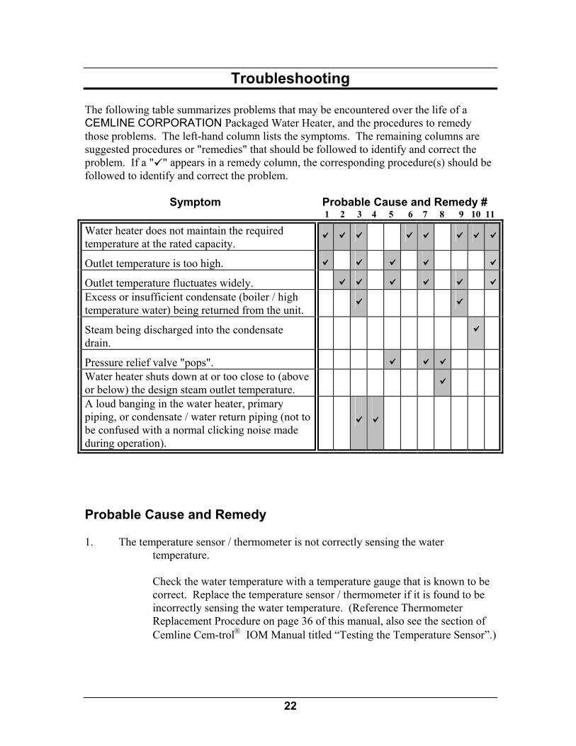
Troubleshooting The following table summarizes problems that may be encountered over the life of a CEMLINE CORPORATION Packaged Water Heater, and the procedures to remedy those problems. The left-hand column lists the symptoms. The remaining columns are suggested procedures or "remedies" that should be followed to identify and correct the problem. If a " " appears in a remedy column, the corresponding procedure(s) should be followed to identify and correct the problem. Symptom Probable Cause and Remedy # 1 2 3 4 5 6 7 8 9 10 11
Water heater does not maintain the required temperature at the rated capacity.
Outlet temperature is too high.
Outlet temperature fluctuates widely. Excess or insufficient condensate (boiler / high temperature water) being returned from the unit.
Steam being discharged into the condensate drain.
Pressure relief valve "pops". Water heater shuts down at or too close to (above or below) the design steam outlet temperature.
A loud banging in the water heater, primary piping, or condensate / water return piping (not to be confused with a normal clicking noise made during operation).
Probable Cause and Remedy 1. The temperature sensor / thermometer is not correctly sensing the water
temperature. Check the water temperature with a temperature gauge that is known to be
correct. Replace the temperature sensor / thermometer if it is found to be incorrectly sensing the water temperature. (Reference Thermometer Replacement Procedure on page 36 of this manual, also see the section of Cemline Cem-trol IOM Manual titled “Testing the Temperature Sensor”.)

23
2. Inlet energy source pressure is too low.
Check the primary energy source pressure gauge. If the reading is low, adjust the inlet pressure to meet the design requirements. If there is a restriction in the primary energy source line, the gauge reading will drop excessively when the generator calls for full energy, even though the pressure seems to be normal during light demand. If the primary pressure is correct, its pressure gauge reading should reach design pressure for energy source in the coil as the temperature of the water in the tank heater approaches shutoff.
3. The condensate / water return piping has not been installed properly, allowing the
condensate / water to drain freely (by gravity); the condensate / water drain line is restricted; or the condensate / water check valve is leaking or has failed.
Reconfigure the condensate / water return piping and check valve to allow
for proper drainage. Check to assure that there is no restriction in the condensate / water drain line. Replace the check valve if it is leaking or has failed. Also, check to assure that there is no restriction in the condensate / water drain line.
4. Primary / inlet steam line is not properly trapped (steam as energy source only). Reconfigure the primary / inlet steam line to allow main and auxiliary
(drip) traps to function properly. 5. The primary / inlet temperature control valve is not closing properly. See the adjustment and testing instructions contained in the supplied
Installation / Operations Manual for the specific temperature control valve installed on the unit. Replace the valve if necessary. (Reference replacement procedure on page 33.)
6. The primary / inlet temperature control valve is not opening properly. See the adjustment and testing instructions contained in the supplied
Installation / Operations Manual for the specific temperature control valve installed on the unit. Replace the valve if necessary. (Reference replacement procedure on page 33.)
7. The secondary / outlet energy source pressure control system is not operating
properly.
See the adjustment and testing instructions contained in the supplied Installation / Operations Manual for the specific temperature / pressure control system installed on the unit. Replace the valve if necessary. (Reference replacement procedure on page 33.)
24
8. The over-temperature limit system is out of adjustment, or some component of the system has failed.
Check the individual components of the system and repair or replace the
failed component(s) as necessary. 9. There is a leak in the heat exchanger or the condensate / water return line causing
water to leak from the tank or energy source system. To verify the existence of a leak, shut off the primary energy source to the
unit and carefully break a connection in the condensate / water return line. CAUTION: The system still contains the primary energy source, possibly
under pressure, and could present a serious potential for injury. Use extreme caution when breaking any connection in the system.
Condensate (boiler or high temperature water) will drain from the heat
exchanger initially, but the flow should stop after a short period of time. If the flow continues, water is leaking from the tank into the heat exchanger. Disassemble, inspect, repair (if possible), or replace the heat exchanger and reassemble the unit. (Reference heat exchanger replacement procedure on page 27.)
10. The heat exchanger is heavily scaled or damaged. Please refer to the enclosed installation, operation, and maintenance
manual for the supplied brazed plate or plate & frame heat exchanger for instructions on cleaning the heat exchanger.
Call CEMLINE, or an authorized sales agent, for instructions on repair or
replacement (800-245-6268). Refer to the nameplate for the model and serial numbers of the unit and heat exchanger coil. Include these numbers in all correspondence.
11. The circulating pump is not moving water through the recirculation line and
through the unit.
Check the circulating pump to verify that it is flowing water through the recirculation line. BPH/PFH style units require the hot water to be drawn across the temperature sensor in the recirculation line for proper temperature control. Pump motor may be spinning, however the impeller may not be moving water. Pump motor may not be spinning and not moving water. Replace pump. (Reference Circulating Pump Inspection and Replacement Prodecure on Page 25 of this manual).

25
Maintenance The information contained in this section will detail service and maintenance procedures for the inspection and replacement of the components of the CEMLINE SPH Packaged Water Heater. Remember, this manual serves both plate & frame and brazed plate heat exchanger SPH Packaged Water Heaters. Therefore, the maintenance procedures may be general in some instances. If there are any questions concerning maintenance procedures that are not clearly explained in this manual, contact CEMLINE CORPORATION. Be sure to have the model and serial numbers of the unit and heat exchanger coil available before making contact. Note: Many of the maintenance procedures detailed in this section will require the unit
to be taken off-line before the procedure is performed; and put back on-line after the procedure is completed. It is recommended that the maintenance personnel performing these procedures review the startup and shutdown procedures, detailed on pages 16 to 18 of this manual, before attempting any maintenance procedure.
Any component(s) directly connected or linked to the component being replaced should carefully be examined before maintenance procedures are started. If any of the related components show signs of wear or improper operation, they should be considered for replacement at the same time. Circulating Pump - Inspection and Replacement CEMLINE Packaged Water Heaters can be equipped with a circulating pump to assist in the even heating of the water. If the unit is equipped with a circulating pump, the following procedure should be followed to replace the pump. 1. Follow Steps 1 through 5 of the shutdown procedure (page 17) to take the unit off-
line before attempting to service the circulating pump.
The combination of electricity and water can pose a very dangerous situation. Turn off / disconnect all electric power before attempting any maintenance procedure.
2. Refer to the manufacturer's documentation supplied with the unit pertaining to
testing the pump. If found to be defective or questionable, replace the pump by continuing with the steps that follow.
3. After assuring that the power has been turned off, disconnect the electric leads to
the circulating pump. 4. Close the manual shutoff valves located near the inlet and outlet ports of the pump.
26
5. Break the joints between the pump and the inlet and outlet piping. Remove the pump.
6. Reconnect the pump to the inlet and outlet piping. Follow recommendations
contained in the manufacturer's documentation, local codes, or accepted contractor practices as to the use and / or type of joint compound or sealer at the connections.
7. Open the manual shutoff valves located on the inlet and outlet sides of the pump
and check for any leakage at the joints. 8. Reconnect the electric leads to the pump (reference wiring diagram provided with
the unit to assure proper wiring). 9. Follow the startup procedures (page 16) to put the unit back on-line. Carefully
check all connections for any sign of leakage. Circulating Pump Shutoff Valves - Replacement If the CEMLINE Packaged Water Heater is equipped with a circulating pump to assist in the even heating of the water, manual shutoff valves will be located on both the inlet and outlet side piping. To replace the valves, follow the procedures detailed below. 1. Follow Steps 1 through 5 of the shutdown procedure (page 17) to take the unit
off-line before attempting to service the circulating pump shutoff valves.
The combination of electricity and water can pose a very dangerous situation. Turn off / disconnect all electric power before attempting any maintenance procedures.
2. After assuring that the power has been turned off, disconnect the electric leads to
the circulating pump. 3. Break the joints between the pump and the inlet and outlet piping. Remove the
pump. 4. Remove the shutoff valves. 5. Install the new valves. Follow recommendations contained in the manufacturer's
documentation, local codes, or accepted contractor practices as to the use and / or type of joint compound or sealer at the connections.
6. Reconnect the pump to the inlet and outlet piping. Follow recommendations
contained in the manufacturer's documentation, local codes, or accepted contractor practices as to the use and / or type of joint compound or sealer at the connections.
7. Open the manual shutoff valves located on the inlet and outlet sides of the pump.
27
8. Reconnect the electric leads to the pump (reference wiring diagram provided with
the unit to assure proper wiring). 9. Follow the startup procedures (page 16) to put the unit back on-line. Carefully
check all joints for any sign of leakage. Power Connections - Rewiring If any of the power connections must be rewired at the circulating pump or electrically activated controls, follow the steps listed below.
The combination of electricity and water can pose a very dangerous situation. Turn off / disconnect all electric power before attempting any maintenance procedure.
1. Follow Steps 1 through 4 of the shutdown procedure (page 17) to take the unit
off-line before attempting any electrical service. 2. After assuring the power has been turned off, disconnect and rewire the electrical
connections in question. 3. Turn the power on and check that the component that has been rewired is
functioning properly. 4. Slowly open the shutoff valves on the boiler water / high temperature water return
(or condensate) line, cold water inlet line, and hot water outlet line. 5. Slowly open the shutoff valves on the energy source inlet line. Brazed Plate Heat Exchanger or Plate & Frame Heat Exchanger and Gaskets - Inspection and Replacement The brazed plate or plate & frame heat exchanger coil is the heart of CEMLINE SPH Packaged Water Heaters. The manufacturer documentation included with the unit gives specifics for the operation and maintenance of the plate heat exchanger. The submittal sheet and C.A.D. drawing included with the unit will give the exact location, as well as interlock with other components. This information should be reviewed before removal / replacement of the plate heat exchanger. Please refer to the enclosed installation, operation, and maintenance manual for the supplied brazed plate or plate & frame heat exchanger.
28
Boiler water, high temperature water, or steam present situations that can be very dangerous because of the high temperatures and pressures. To avoid possible injury or death, use common sense and follow all accepted and recommended procedures when performing installation, operation, and maintenance procedures.
The combination of electricity and water can pose a very dangerous situation.
Turn off / disconnect all electric power before attempting any maintenance procedures.
1. Follow Steps 1 through 5 of the shutdown procedure (page 17) to take the unit
off-line before attempting to remove and inspect the heat exchanger coil. 2. Assure that the energy source, condensate / water return line, cold water inlet, and
hot water outlet have been shut off; that the tank has been completely drained; that the pressure has been bled from both the water and energy source systems; and that the water, all components, and surfaces have cooled.
3. Close the shut off valves between the heat exchanger and the tank on the domestic
water side. 4. Carefully break the connections between the heat exchanger and the domestic
water side. 5. Carefully break the connections between the heat exchanger and the energy source
inlet and outlet lines. Note: It may be necessary to break the lines at a second location, and for the lines to
be rotated to allow clearance for the heat exchanger coil to be removed from the tank. If it is necessary, care should be taken to insure that in-line components are not damaged.
6. Carefully separate the heat exchanger from the unit.
There may still be residual boiler / high temperature water (or residual steam) in the heat exchanger that can run out during removal of the heat exchanger from the water heater. If sufficient time has not been allowed for cooling, this residual condensate / water could present a danger of injury.
7. Examine the heat exchanger for scale buildup and signs of leakage. If no leakage
is detected, carefully clean the excess scale from the heat exchanger. Please refer to the enclosed installation, operation, and maintenance manual for the supplied brazed plate or plate & frame heat exchanger. If leakage is detected either repair the leaking heat exchanger or replace the heat exchanger. Please refer to the enclosed installation, operation, and maintenance manual for the supplied brazed plate or plate & frame heat exchanger.
29
8. Carefully reconnect the connections between the heat exchanger and the domestic water side.
9. Carefully reconnect the connections between the heat exchanger and the energy
source inlet and outlet lines. 10. Open the shut off valves between the heat exchanger and the tank on the domestic
water side. 11. Reconnect the energy source inlet and outlet lines to the heat exchanger. If these
lines were broken at an additional location to allow for removal of the heat exchanger, be sure to also tighten those connections. Follow recommendations contained in the manufacturer's documentation, local codes, or accepted contractor practices as to the use and / or type of joint compound or sealer at the connections.
12. Reconnect the small line leading to the energy source pressure gauge.
If the unit is equipped with a circulating pump, the pump relay must be interlocked with the temperature control valve so that the energy source will shut off if the pump is not operational. Failure to do so could create a very dangerous situation if the pump were to fail.
13. Follow the startup procedures (page 16) to put the unit back on-line. Carefully
check all connections for any sign of leakage. Inlet, Outlet, and Water Return / Condensate Line and Manual Shutoff Valves - Replacement If any of the inlet, outlet, return lines, or shutoff valves are damaged and must be replaced, follow the steps outlined below.
The combination of electricity and water can pose a very dangerous situation. Turn off / disconnect all electric power before attempting any maintenance procedures.
1. Follow Steps 1 through 5 of the shutdown procedure (page 17) to take the unit off-
line before attempting to replace damaged lines or shutoff valves.
While it might seem feasible to replace inlet, outlet, water return / condensate lines, and shutoff valves without shutting down the entire unit, it is not advised. Unless the unit is completely shutdown, and water and the energy source are isolated from the system, failure of a manual shutoff valve during the replacement process could result in serious injury.
2. Assure that the energy source, water return / condensate line, cold water inlet, and
hot water outlet have been shut off; that the tank has been completely drained; that

30
the pressure has been bled from both the water and energy source systems; and that all components and surfaces have cooled.
3. Carefully break the joint between the unit and the line or valve to be replaced. 4. Remove the section of line or valve to be replaced. 5. Replace the damaged section of line or valve. 6. Reconnect the line or valve to the unit. Follow recommendations contained in the
manufacturer's documentation, local codes, or accepted contractor practices as to the use and / or type of joint compound or sealer at the connections.
7. Follow the startup procedures (page 16) to put the unit back on-line. Carefully
check all connections for any sign of leakage. Temperature or Pressure Gauge (Energy Source) - Replacement If the pressure gauge for the energy source does not function correctly and must be replaced, follow the procedures outlined below.
The combination of electricity and water can pose a very dangerous situation. Turn off / disconnect all electric power before attempting any maintenance procedure.
1. Follow Steps 1 through 5 of the shutdown procedure (page 17) to take the unit off-
line before attempting to replace the energy source temperature / pressure gauge. 2. Carefully remove the gauge from the heat exchanger.. 3. Reconnect the new gauge to the heat exchanger. Follow recommendations
contained in the manufacturer's documentation, local codes, or accepted contractor practices as to the use and / or type of joint compound or sealer at the connections.
5. Follow the startup procedures (page 16) to put the unit back on-line. Carefully
check all connections for any sign of leakage. Pressure Gauge (Water) - Replacement If the pressure gauge for the water tank is not functioning correctly and must be replaced, follow the procedures outlined below.

31
The combination of electricity and water can pose a very dangerous situation. Turn off / disconnect all electric power before attempting any maintenance procedures.
1. Follow Steps 1 through 5 of the shutdown procedure (page 17) to take the unit off-
line before attempting to replace the water pressure gauge. 2. Carefully disconnect the small line connecting the pressure gauge with the tank.
This line should only be disconnected at the gauge. 3. Remove the gauge from its mounting. 4. Mount the new gauge. 5. Reconnect the small line to the gauge. Follow recommendations contained in the
manufacturer's documentation, local codes, or accepted contractor practices as to the use and / or type of joint compound or sealer at the connections.
6. Follow the startup procedures (page 16) to put the unit back on-line. Carefully
check all connections for any sign of leakage. Pressure Relief Valve (Tank) - Replacement If the water pressure relief valve mounted on the tank is not functioning correctly and must be replaced, follow the procedures outlined below.
The combination of electricity and water can pose a very dangerous situation. Turn off / disconnect all electric power before attempting any maintenance procedure.
1. Follow Steps 1 through 5 of the shutdown procedure (page 17) to take the unit off-
line before attempting to replace the water pressure relief valve. 2. Disconnect the vent line leading from the water pressure release valve to the drain. 3. Carefully unscrew the water pressure relief valve from the port in the tank. 4. Install the new valve by screwing it into the pressure relief valve port in the tank.
Follow recommendations contained in the manufacturer's documentation, local codes, or accepted contractor practices as to the use of joint compound or sealer at the connections.
5. Reconnect the vent line leading from the water pressure relief valve to the drain. 6. Follow the startup procedures (page 16) to put the unit back on-line. Carefully
check all connections for any sign of leakage.
32
Single Solenoid Safety System - Inspection and Replacement The single solenoid safety system closes the control valve in an over-temperature condition. The system should be checked semi-annually. (See manufacturer's documentation for the solenoid safety system provided with the unit for specific inspection intervals and test routine). If the system is found to be malfunctioning and must be replaced, follow the procedure outlined below. Note: The exact location and configuration of the single solenoid safety system can
vary between Series and units. See the C.A.D. drawing supplied with the Submittal sheet and design specifications supplied with the unit for the exact placement and configuration.
The combination of electricity and water can pose a very dangerous situation.
Turn off / disconnect all electric power before attempting any maintenance procedure.
1. Follow Steps 1 through 5 of the shutdown procedure (page 17) to take the unit off-
line before attempting to replace the single solenoid safety system. 2. Carefully disconnect the small line connecting the single solenoid safety system to
the energy source control valve. This line should only be disconnected at the safety system.
3. Carefully disconnect the small line connecting the single solenoid safety system to
the tank or hot water outlet line. This line should only be disconnected at the safety system.
4. If the system is electrically activated, turn off the power and disconnect the electric
leads from the safety system. 5. Remove the safety system from its mounting. 6. Mount the new safety system. 7. Reconnect the small line from the tank or hot water outlet line to the safety system.
Follow recommendations contained in the manufacturer's documentation, local codes, or accepted contractor practices as to the use and / or type of joint compound or sealer at the connections.
8. Reconnect the small line from the energy source control valve to the safety system. 9. Reference the manufacturer's documentation for the safety system that was
supplied with your unit for additional installation / setup instructions. 10. Follow the startup procedures (page 16) to put the unit back on-line. Carefully
check all connections for any sign of leakage.

33
Water Dump Valve - Inspection and Replacement The water dump valve (double solenoid safety system) opens at a set point, normally higher than the single solenoid safety system set point, and dumps the hot water in the heater to drain. The system should be checked semi-annually. (See manufacturer's documentation for the solenoid safety system provided with the unit for specific inspection intervals and test routine). If the system is found to be malfunctioning and must be replaced, follow the procedure outlined below. Note: The exact location and configuration of the water dump valve can vary between
Series and units. See the C.A.D. drawing supplied with the Submittal sheet and design specifications supplied with the unit for the exact placement and configuration.
The combination of electricity and water can pose a very dangerous situation.
Turn off / disconnect all electric power before attempting any maintenance procedure.
1. Follow Steps 1 through 5 of the shutdown procedure (page 17) to take the unit off-
line before attempting to replace the water dump valve. 2. Carefully disconnect the line connecting the water dump valve with the tank. This
line should only be disconnected at the safety system. 3. Carefully disconnect the line connecting the water dump valve to the drain line.
This line should only be disconnected at the safety system. 4. If the system is electrically activated, turn off the power and disconnect the electric
leads from the water dump valve. 5. Remove the water dump valve from its mounting. 6. Mount the new water dump valve. 7. Reconnect the small line from the tank or hot water outlet line to the dump valve.
Follow recommendations contained in the manufacturer's documentation, local codes, or accepted contractor practices as to the use and / or type of joint compound or sealer at the connections.
8. Reconnect the water dump valve to the drain line. 9. Reference the manufacturer's documentation for the safety system that was
supplied with your unit for additional installation / setup instructions. 10. Follow the startup procedures (page 16) to put the unit back on-line. Carefully
check all connections for any sign of leakage

34
Strainer - Inspection and Replacement The strainer is installed upstream of the energy source shutoff valves for both the boiler water inlet / outlet. The strainer must be blown down periodically (approximately every three (3) to six (6) months) to prevent the build up of any sediment.
The combination of electricity and water can pose a very dangerous situation. Turn off / disconnect all electric power before attempting any maintenance procedures.
1. Follow Steps 1 through 5 of the shutdown procedure (page 17) to take the unit off-
line before attempting to replace the energy source pressure gauge. 2. The exact location of the strainers can differ between Series and units. Reference
the C.A.D. drawing supplied with the Submittal sheet for the unit to identify the location of the strainers on the unit.
3. Carefully break the line connections on the inlet side of the strainer. 4. Carefully break the line connection on the outlet side of the strainer. 5. Remove and examine the strainer. 6. Remove any sediment that is present in the strainer. If they can not be
satisfactorily cleaned, replace with new strainer. 7. Place the strainer back in-line in the system. 8. Reconnect the inlet and outlet lines to the strainer. Follow recommendations
contained in the manufacturer's documentation, local codes, or accepted contractor practices as to the use and / or type of joint compound or sealer at the connections.
9. Follow the startup procedures (page 16) to put the unit back on-line. Carefully
check all connections for any sign of leakage. Temperature Control Valve - Inspection and Replacement The temperature control valve is installed upstream of the heat exchanger and must be interlocked with the high temperature cutoff solenoid. The manufacturer documentation included with the unit gives specifics for operation and maintenance of the control valve. The Submittal sheet and C.A.D. drawing included with the unit will give the exact location, as well as interlocks with other components. This information should be reviewed before removal / replacement of the temperature control valve.
Boiler water, high temperature water, or steam present situations that can be very dangerous because of the high temperatures and pressures. Use common sense
35
and follow all accepted and recommended procedures when performing installation, operation, and maintenance procedures to avoid possible injury or death.
The combination of electricity and water can pose a very dangerous situation.
Turn off / disconnect all electric power before attempting any maintenance procedures.
1. Follow Steps 1 through 5 of the shutdown procedure (page 17) to take the unit off-
line before attempting to remove and inspect the temperature control valve. 2. Assure that the energy source, boiler water / condensate return line, cold water
inlet, and hot water outlet have been shut off; that the tank has been completely drained; that the pressure has been bled from both the water and energy source systems; and that all components and surfaces have cooled.
3. If the temperature control valve is electrically activated, turn off the power and
disconnect the leads to the valve. 4. Carefully break the joints between the temperature control valve and pump relay,
single solenoid safety unit, and the auxiliary trap line. 5. Carefully break the connections between the energy source inlet line and the heat
exchanger. Note: It may be necessary to break the lines at a second location, and for the lines to
be rotated to allow clearance for the temperature control valve to be removed from the system. If it is necessary, care should be taken to insure that in-line components are not damaged.
6. Remove the temperature control valve from the system. 7. Follow the supplied manufacturer instructions for inspecting the valve. If found to
be malfunctioning, replace the valve. 8. Carefully replace the temperature control valve into the system by reattaching it to
the energy source inlet line and the heat exchanger outlet line. Follow recommendations contained in the manufacturer's documentation, local codes, or accepted contractor practices as to the use and / or type of joint compound or sealer at the connections.
9. Align the valve as it was situated before removal and tighten the connections. If
lines were broken at an additional location to allow for removal of the valve, be sure to also tighten those connections.
10. Reconnect the temperature control valve to the pump or pump relay, single
solenoid safety unit, and the auxiliary trap line.

36
If the unit is equipped with a circulating pump, the pump relay must be
interlocked with the temperature control valve so that the energy source will shut off if the pump is not operational. Failure to do so could create a very dangerous situation if the pump were to fail.
11. Follow the startup procedures (page 16) to put the unit back on-line. Carefully
check all connections for any sign of leakage. Thermometer - Replacement If the thermometer for the hot water is not functioning correctly and must be replaced, follow the procedures outlined below.
The combination of electricity and water can pose a very dangerous situation. Turn off / disconnect all electric power before attempting any maintenance procedures.
1. Follow Steps 1 through 5 of the shutdown procedure (page 17) to take the unit off-
line before attempting to replace the thermometer. 2. Carefully disconnect the small line connecting the thermometer with the tank.
This line should only be disconnected at the gauge. 3. Remove the thermometer from its mounting. 4. Mount the new thermometer. 5. Reconnect the small line to the thermometer. Follow recommendations contained
in the manufacturer's documentation, local codes, or accepted contractor practices as to the use and / or type of joint compound or sealer at the connections.
6. Follow the startup procedures (page 16) to put the unit back on-line. Carefully
check all connections for any sign of leakage. Traps (Main and Auxiliary) - Replacement (Steam Systems Only) The main and auxiliary traps are installed upstream of the condensate shutoff valve on units that use steam as the energy source. The traps are designed to maintain the flow of condensate with the rise and fall of the float as changes in condensate level occur within the body of the trap. If the traps are not functioning properly and must be replaced, follow the procedures outlined below.
The combination of electricity and water can pose a very dangerous situation. Turn off / disconnect all electric power before attempting any maintenance procedures.

37
1. Follow Steps 1 through 5 of the shutdown procedure (page 17) to take the unit off-
line before attempting to replace the main or auxiliary traps. 2. The exact location of the traps can differ between series and units. Reference the
Submittal sheet and C.A.D. drawing supplied with the unit to identify the location of the traps on the unit.
3. Carefully break the joint on the inlet side of both traps. 4. Carefully break the joint on the outlet side of the traps. 5. Remove and examine the traps. 6. If the traps are not functioning properly, replace them with new traps. 7. Place the traps back in-line in the system. 8. Reconnect the inlet and outlet lines to each trap. Follow recommendations
contained in the manufacturer's documentation, local codes, or accepted contractor practices as to the use and / or type of joint compound or sealer at the connections.
9. Follow the startup procedures (page 16) to put the unit back on-line. Carefully
check all connections for any sign of leakage

38
CEMLINE CORPORATION P. O. Box 55
Cheswick, PA, 15024 Phone: (724) 274-5430
FAX (724) 274-5448 www.cemline.com