
SpeedSentry Radar Speed Display - All Traffic …...SpeedSentry Radar Speed Display All Traffic...
31
SpeedSentry Radar Speed Display All Traffic Solutions 3100 Research Drive State College, Pennsylvania 16801 www.alltrafficsolutions.com [email protected] 814-237-9005
Transcript of SpeedSentry Radar Speed Display - All Traffic …...SpeedSentry Radar Speed Display All Traffic...

SpeedSentry Radar Speed Display
All Traffic Solutions 3100 Research Drive State College, Pennsylvania 16801www.alltrafficsolutions.com [email protected] 814-237-9005
SpeedSentry Radar Speed Display
Shield Radar Speed Display Introduction1
Speedsentry Factory Recertified Radar Speed Display 41.1
Radar Speed Display Quick Starts2
Speedsentry Factory Recertified Quick Start 62.1
Quick Start: Setting up a Speed Display with Smart Apps 102.2
Power3
Pole Mount with SLA Battery - Speedsentry 12 133.1
AC Power - SpeedSentry 12 143.2
Pole mounted Solar with SLA (Sealed Lead Acid) Battery - SpeedSentry 153.3
Deployment4
Setup - Speedsentry Speed Display 184.1
Controls and Settings5
Control and Interface Options Explained 225.1
On-Board Controls6
Speedsentry 12 On-Board Controls 256.1
Shield 18 On-Board Controls (Pre-2010 units) 276.2
Care and Maintenance7
Warranty 297.1
Battery Maintenance and Warnings 307.2

SpeedSentry Radar Speed Display - 3
Shield Radar Speed Display Introduction
SpeedSentry Radar Speed Display - 4
Speedsentry Factory Recertified Radar Speed Display
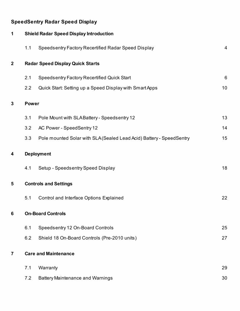
The SPEEDsentry is a portable and flexible radar speed display sign
ideal anywhere traffic calming is essential. Drivers receive instant
feedback based on their speed from the 12” display. The sign provides
easy mounting and programming, and it offers a wide variety of options
to suit your needs. The Speedsentry can be powered by a sealed lead
acid battery for portable applications, and can be augmented with solar
changing or AC power for permanent applications.

SpeedSentry Radar Speed Display - 5
Radar Speed Display Quick Starts
SpeedSentry Radar Speed Display - 6
Speedsentry Factory Recertified Quick Start
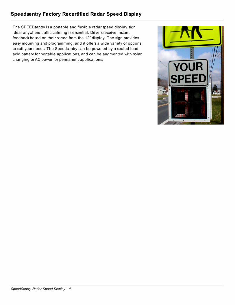
Unpack the Speedsentry
Remove the unit, batteries, and charger kit from the boxes.
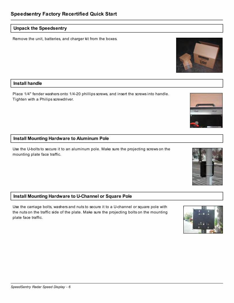
Install handle
Place 1/4" fender washers onto 1/4-20 phil l ips screws, and insert the screws into handle.
Tighten with a Philips screwdriver.
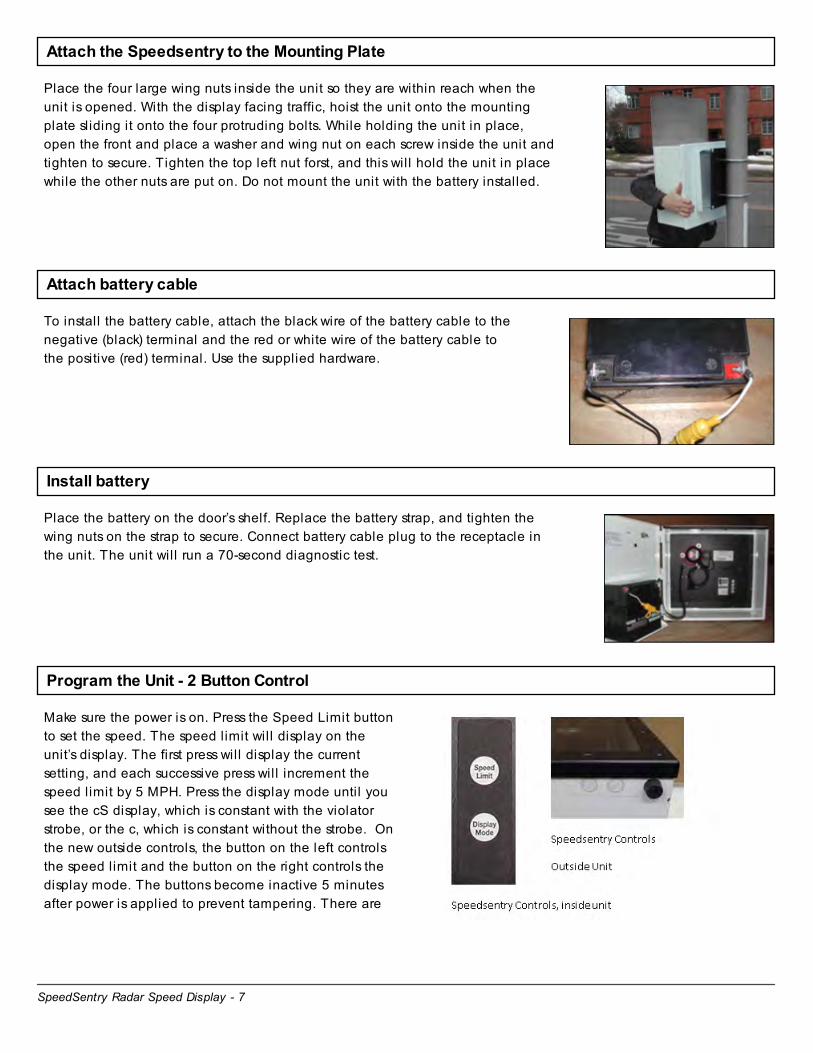
Install Mounting Hardware to Aluminum Pole
Use the U-bolts to secure it to an aluminum pole. Make sure the projecting screws on the
mounting plate face traffic.
Install Mounting Hardware to U-Channel or Square Pole
Use the carriage bolts, washers and nuts to secure it to a U-channel or square pole with
the nuts on the traffic side of the plate. Make sure the projecting bolts on the mounting
plate face traffic.
SpeedSentry Radar Speed Display - 7
Attach the Speedsentry to the Mounting Plate
Place the four large wing nuts inside the unit so they are within reach when the
unit is opened. With the display facing traffic, hoist the unit onto the mounting
plate sliding it onto the four protruding bolts. While holding the unit in place,
open the front and place a washer and wing nut on each screw inside the unit and
tighten to secure. Tighten the top left nut forst, and this will hold the unit in place
while the other nuts are put on. Do not mount the unit with the battery installed.
Attach battery cable
To install the battery cable, attach the black wire of the battery cable to the
negative (black) terminal and the red or white wire of the battery cable to
the positive (red) terminal. Use the supplied hardware.
Install battery
Place the battery on the door’s shelf. Replace the battery strap, and tighten the
wing nuts on the strap to secure. Connect battery cable plug to the receptacle in
the unit. The unit will run a 70-second diagnostic test.
Program the Unit - 2 Button Control
Make sure the power is on. Press the Speed Limit button
to set the speed. The speed limit wil l display on the
unit’s display. The first press will display the current
setting, and each successive press will increment the
speed limit by 5 MPH. Press the display mode until you
see the cS display, which is constant with the violator
strobe, or the c, which is constant without the strobe. On
the new outside controls, the button on the left controls
the speed limit and the button on the right controls the
display mode. The buttons become inactive 5 minutes
after power is applied to prevent tampering. There are

SpeedSentry Radar Speed Display - 8
more display options covered in the manual. See
Speedsentry On-Board Controls for more information on
the settings available on the unit.
Program the Unit - 2 Button Control
Make sure the power is on. Press the Speed Limit button
to set the speed. The speed limit wil l display on the
unit’s display. The first press will display the current
setting, and each successive press will increment the
speed limit by 5 MPH. Press the display mode until you
see the cS display, which is constant with the violator
strobe, or the c, which is constant without the strobe. On
the new outside controls, the button on the left controls
the speed limit and the button on the right controls the
display mode. The buttons become inactive 5 minutes
after power is applied to prevent tampering. There are
more display options covered in the manual. See
Speedsentry On-Board Controls for more information on
the settings available on the unit.
Program the Unit - 4 Button Control with LCD
Turn the power on with the Power button. Step through the
settings with the Settings button. Change settings with the
up and down arrows. To get started, set the speed limit, set
the radar to always on, the display to always on and the
violator strobe to the speed limit.

SpeedSentry Radar Speed Display - 9
Install “Your Speed” Sign
With the supplied wrench, remove bolts and washers on the left and right side of the “Your
Speed” sign. Rotate the sign so the words “YOUR SPEED” face traffic. Reattach the bolts
and tighten to secure. Do not loosen the center screw as this is the rotating hardware.
Ready to go
The SPEEDsentry is installed and ready for use.
SpeedSentry Radar Speed Display - 10
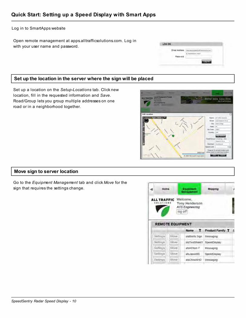
Quick Start: Setting up a Speed Display with Smart Apps
Log in to SmartApps website
Open remote management at apps.alltrafficsolutions.com. Log in
with your user name and password.
Set up the location in the server where the sign will be placed
Set up a location on the Setup-Locations tab. Click new
location, fi l l in the requested information and Save.
Road/Group lets you group multiple addresses on one
road or in a neighborhood together.
Move sign to server location
Go to the Equipment Management tab and click Move for the
sign that requires the settings change.

SpeedSentry Radar Speed Display - 11
Set Move location and update settings
In the move dialog, select the new location that was
created, and select Pending Move. Check Assign new
settings and enter the desired display settings. Click
Apply Changes.
Mount the sign and tell the server that it has "Moved"
Mount the sign at the designated location in the field and turn it on. Initiate the Move Sign function by
holding the speed limit and display settings buttons on the unit at the same time. This will make the sign call
in, get the new settings and start to assign recorded data to this location.

SpeedSentry Radar Speed Display - 12
Power

SpeedSentry Radar Speed Display - 13
Pole Mount with SLA Battery - Speedsentry 12
Sealed Lead Acid Power for pole mount Speedsentry speed displays
Attach Battery Leads
To prepare the battery for installation, first attach the black wire of the battery cable to
the negative (black) terminal. Then attach the red or white wire of the battery cable to
the red (positive) terminal. Do not reverse polarity. The fuse is a 10A, 32V 3AG time
delay. Replace only with a 10A, 32V 3AG time delay fuse.
Install Battery into Speedsentry
Hook up the battery after you secure the unit to the mounting plate. Open the
Speedsentry, place the battery on the shelf, and install the battery bracket. Connect
the battery cable to the receptacle in the unit. The unit wil l now return to the settings
from the last time the power was removed.
Connect Solar, if applicable
If the unit has solar, install the panel per the step below and connect the solar panel harness to the connector
on the bottom of the unit.
Start Up
Every time you connect the Speedsentry's battery and press power, the display performs a startup test. It
flashes the lights and strobe on the display and runs through a brightness cycle. The display shows patterns
rather than specific numbers. This test takes about 15 seconds. Wait for this test to complete before
performing other functions on the Speedsentry.

SpeedSentry Radar Speed Display - 14
AC Power - SpeedSentry 12
AC Power for Speed Displays
CAUTION: High voltages present in AC Supply. Follow all applicable electrical codes when connecting the SPEEDsentry to the power line. Ground enclosure according to all applicable codes. Disconnect AC power before installation. Service should only be done by qualified personnel.
AC Power connections for Speedsentry SS12
• Mount the SPEEDsentry in the desired location.
• Disconnect AC power to the power supply l ine.
• Dril l a .875” diameter hole for the provided cord
grip fitting in the SPEEDsentry enclosure where
desired. See image for recommended location
(placing the hole in the back lid of the unit wil l
allow the front of the unit to swing open).
• Place the provided cord grip fitting into the dril led
hole and secure by tightening the nut on the
inside.
• Bring AC line through fitting to the outside of the
unit. Tighten the cord grip fitting around the cable.
• Make the AC Connections:
• Black wire to Line/Hot
• White wire to Neutral
• Green wire to Ground using preferred method
(twist-on wire connectors are provided).
• Also provided is a small weatherproof box to
further protect this connection. If preferred, this box
can also be mounted inside the SpeedSentry.
• Plug the SPEEDsentry DC power connector from
the AC power supply into the SPEEDsentry power
input receptacle below and to the left of the radar .
(Note that this DC plug can be disconnected and
the SPEEDsentry can then be operated with a
battery connected to the power input receptacle.)
• Apply AC power.
• The SPEEDsentry is ready for use. Configure
according to the SPEEDsentry instructions.
• When power is removed and reapplied, the
Speedsentry will return to the same operating
mode as when power was removed.

SpeedSentry Radar Speed Display - 15
Pole mounted Solar with SLA (Sealed Lead Acid) Battery - SpeedSentry
Mounting solar panels on pole and connecting SpeedSentry, Shield and SpeedAlert signs.
Solar Panel
• The solar panels work with the solar controller located in the system's battery compartment or in the
trailer’s battery box. The controller continually recharges the batteries up to full whenever sufficient
sunlight generates a charging current. It prevents overcharging the batteries and draining the batteries
during low-light periods.
• Appropriate panel size for solar assist depends on display sign model, traffic volume, geographic
location, battery capacity and operating times. Actual performance depends on application and
mounting location. Contact All Traffic Solutions for help in selecting an appropriately sized panel and
battery combination.
• Place panels in direct sunlight and ti lt them toward toward true south to maximize their effectiveness.
To calculate the best angle of ti lt in the winter when there are the least sun hours, take your latitude,
multiply by 0.89, and add 24 degrees. The result is the angle from the horizontal at which the panel
should be ti lted.
• Mount the speed display unit so the display remains out of direct sunlight whenever possible for optimal
viewing.
• ATS uses Sealed Lead Acid batteries for solar systems, as charging lithium batteries in extreme hot or
cold temperatures can damage the battery.
Mounting the Solar Panel to a pole
Notes:
• Solar panels will all mount similarly, though actual
bolt positioning on the Panel Supports may vary.
• Bracket shown banded to a standard 4.5” diameter
pole. Bracket can also be mounted with U-bolts
(not provided).
Installation Steps
1. Lay solar panel face down on a protective surface
and attach panel supports with supplied hardware
(HHMS* ¼-20 x .75 (qty4), lock washer ¼ (qty4),
washer ¼ (qty8), nut ¼-20 (qty4)) and finger tighten.
2. Attach end clips to bucket using supplied hardware
(HHMS 5/16-20 x .75 (qty4), lock washer 5/16 (qty4),
washer 5/16 (qty8), nut 5/16-18 (qty4)) and finger
tighten.
3. Attach panel supports to end clip with supplied
hardware (HHMS 5/16-20 x .75 (qty4), lock washer
5/16 (qty4), washer 5/16 (qty8), nut 5/16-18 (qty4)) and
finger tighten.
4. Attach bucket to pole using U-bolt or banding.
5. Adjust the ti lt angle to the recommended angle
above.
6. Tighten all hardware until the lock washer is flat.
SpeedSentry Radar Speed Display - 16
7. Tie power cord to pole with nylon ties and connect to
the solar panel connector on the battery box.
*Hex Head Machine Screw
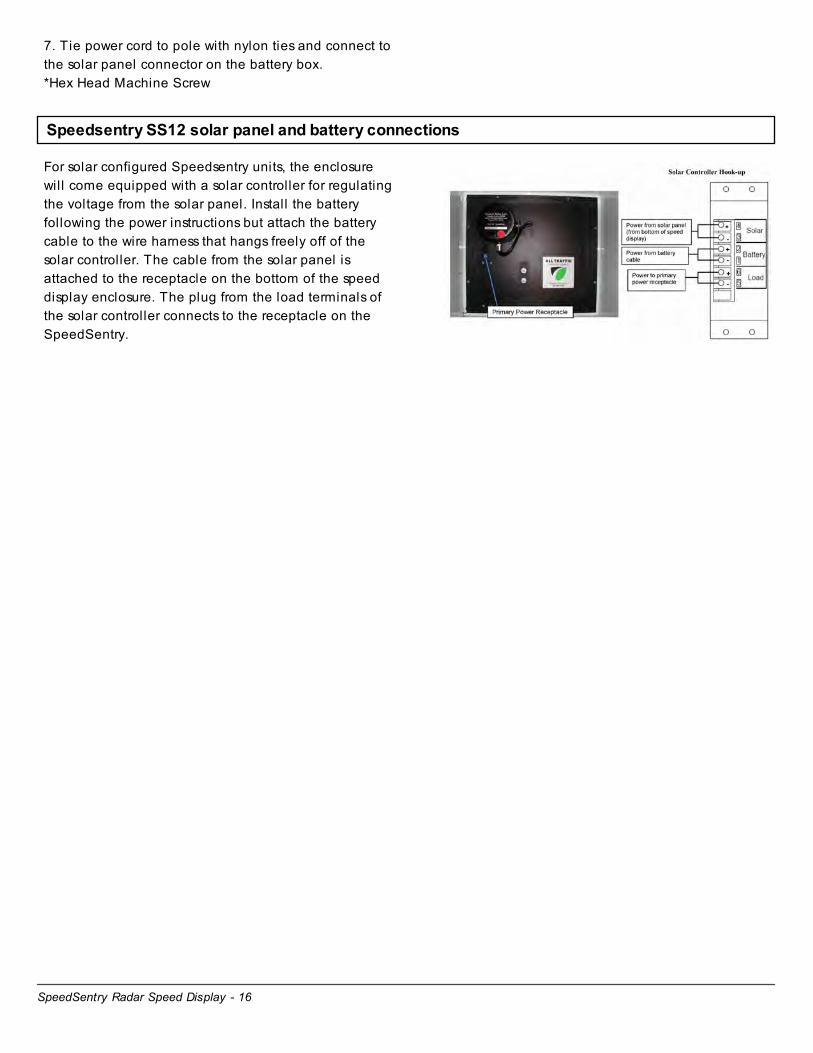
Speedsentry SS12 solar panel and battery connections
For solar configured Speedsentry units, the enclosure
will come equipped with a solar controller for regulating
the voltage from the solar panel. Install the battery
following the power instructions but attach the battery
cable to the wire harness that hangs freely off of the
solar controller. The cable from the solar panel is
attached to the receptacle on the bottom of the speed
display enclosure. The plug from the load terminals of
the solar controller connects to the receptacle on the
SpeedSentry.

SpeedSentry Radar Speed Display - 17
Deployment

SpeedSentry Radar Speed Display - 18
Setup - Speedsentry Speed Display
This section covers the setup and installation of the SPEEDsentry unit, including the attaching the handle,
identifying a proper location, mounting the unit, and positioning the “YOUR SPEED” sign.
Attaching the Handle
To attach the handle to the unit for easy carrying, use the included molded plastic
handle, 2 washers, 2 small screws, and a Phill ips screwdriver. Remove the plugs
from the holes on the top of the unit. Align the handle with the predril led holes on
top of the unit. Add fender washers to 1/4-20 screws and tighten both through hole
into handle from inside the unit.
Identify Location
The SPEEDsentry mounts to a pole, a vehicle hitch, or
a trailer. Pole-mounting options include a 4” aluminum
pole, a U-channel pole, square pole and other
available poles.
Choose a location near enough to the road to allow the
SPEEDsentry to face oncoming traffic as directly as
possible. Pointing the unit with a smaller angle ensures
greater accuracy of the radar. Mount the unit at a height
of 6’ to 8’ to the center of the display, if possible, for
optimal performance. Avoid mounting the unit with
direct sunlight on the face whenever possible. No matter
the mounting option you choose, make sure the
location prevents the unit from interfering with traffic.
NOTE: These same considerations also apply if you use
a ATS-5 trailer.
Fasten Mounting Bracket
The mounting bracket allows multiple options for attachment to a pole. Holes in
the mounting bracket accommodate U-bolts (included), carriage bolts (included),
and metal bands (not included).
NOTE: The SS12 is NCHRP 350 accepted when mounted to a 4” aluminum pole
with a breakaway base using the supplied U bolts with the SPEEDsentry mounted
at least 5’ above the ground to the bottom of the unit and with a 26Ah battery
installed. (Acceptance letter SS-135)
SpeedSentry Radar Speed Display - 19
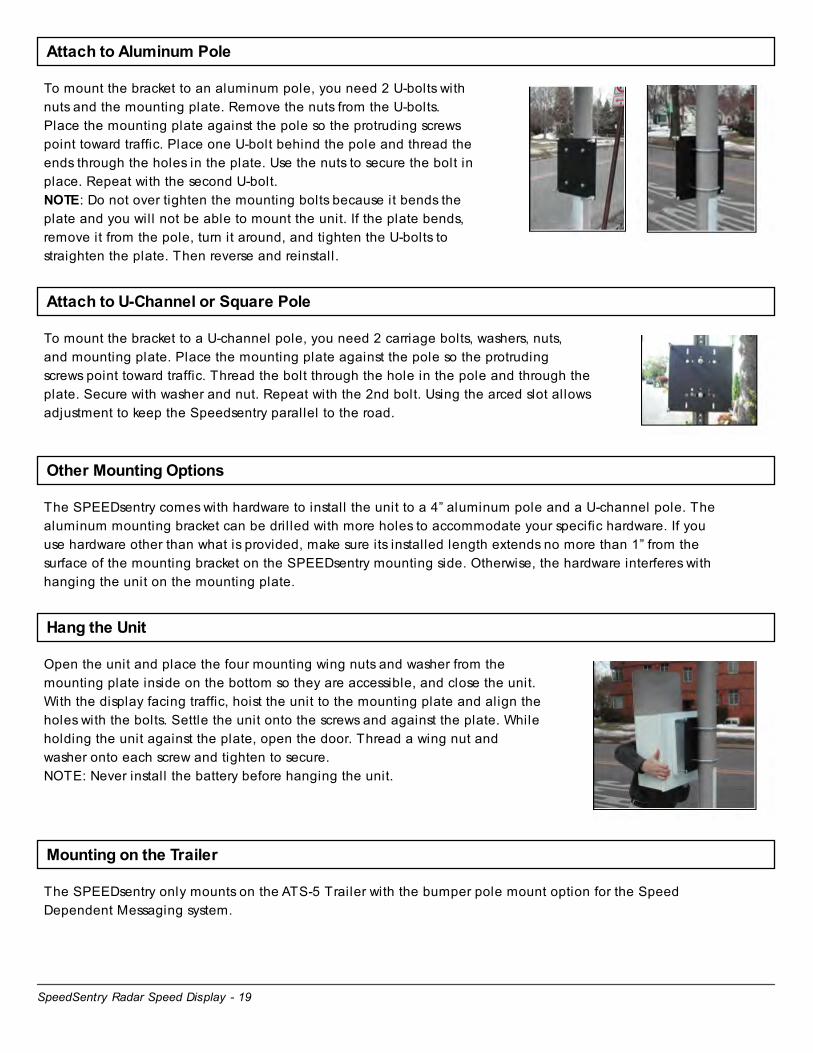
Attach to Aluminum Pole
To mount the bracket to an aluminum pole, you need 2 U-bolts with
nuts and the mounting plate. Remove the nuts from the U-bolts.
Place the mounting plate against the pole so the protruding screws
point toward traffic. Place one U-bolt behind the pole and thread the
ends through the holes in the plate. Use the nuts to secure the bolt in
place. Repeat with the second U-bolt.
NOTE: Do not over tighten the mounting bolts because it bends the
plate and you will not be able to mount the unit. If the plate bends,
remove it from the pole, turn it around, and tighten the U-bolts to
straighten the plate. Then reverse and reinstall.
Attach to U-Channel or Square Pole
To mount the bracket to a U-channel pole, you need 2 carriage bolts, washers, nuts,
and mounting plate. Place the mounting plate against the pole so the protruding
screws point toward traffic. Thread the bolt through the hole in the pole and through the
plate. Secure with washer and nut. Repeat with the 2nd bolt. Using the arced slot allows
adjustment to keep the Speedsentry parallel to the road.
Other Mounting Options
The SPEEDsentry comes with hardware to install the unit to a 4” aluminum pole and a U-channel pole. The
aluminum mounting bracket can be dril led with more holes to accommodate your specific hardware. If you
use hardware other than what is provided, make sure its installed length extends no more than 1” from the
surface of the mounting bracket on the SPEEDsentry mounting side. Otherwise, the hardware interferes with
hanging the unit on the mounting plate.
Hang the Unit
Open the unit and place the four mounting wing nuts and washer from the
mounting plate inside on the bottom so they are accessible, and close the unit.
With the display facing traffic, hoist the unit to the mounting plate and align the
holes with the bolts. Settle the unit onto the screws and against the plate. While
holding the unit against the plate, open the door. Thread a wing nut and
washer onto each screw and tighten to secure.
NOTE: Never install the battery before hanging the unit.
Mounting on the Trailer
The SPEEDsentry only mounts on the ATS-5 Trailer with the bumper pole mount option for the Speed
Dependent Messaging system.
SpeedSentry Radar Speed Display - 20
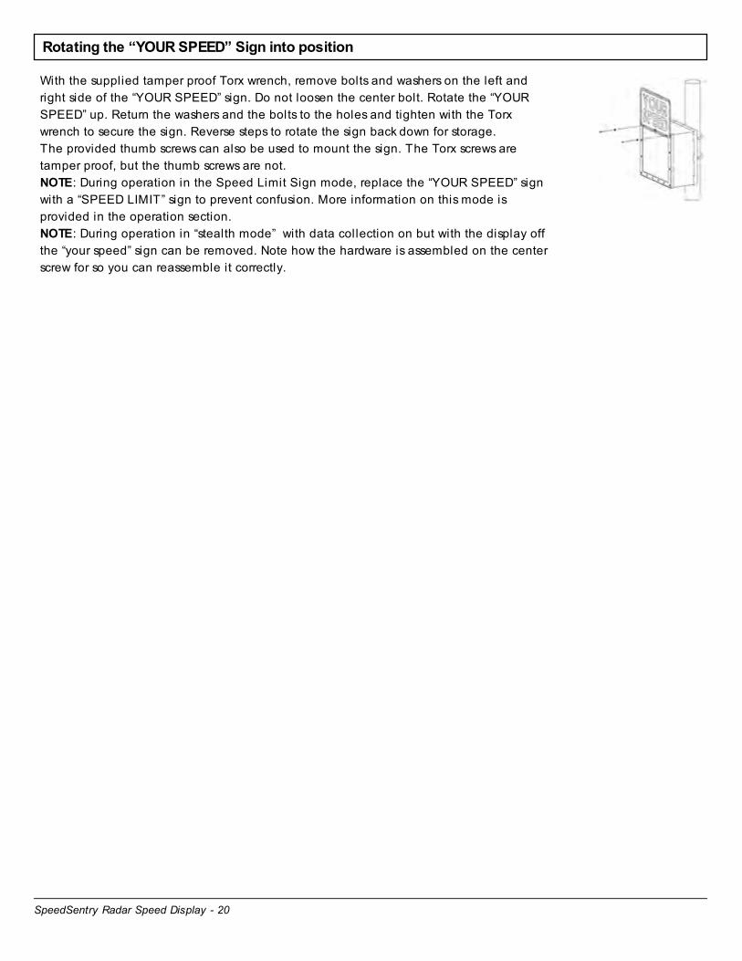
Rotating the “YOUR SPEED” Sign into position
With the supplied tamper proof Torx wrench, remove bolts and washers on the left and
right side of the “YOUR SPEED” sign. Do not loosen the center bolt. Rotate the “YOUR
SPEED” up. Return the washers and the bolts to the holes and tighten with the Torx
wrench to secure the sign. Reverse steps to rotate the sign back down for storage.
The provided thumb screws can also be used to mount the sign. The Torx screws are
tamper proof, but the thumb screws are not.
NOTE: During operation in the Speed Limit Sign mode, replace the “YOUR SPEED” sign
with a “SPEED LIMIT” sign to prevent confusion. More information on this mode is
provided in the operation section.
NOTE: During operation in “stealth mode” with data collection on but with the display off
the “your speed” sign can be removed. Note how the hardware is assembled on the center
screw for so you can reassemble it correctly.

SpeedSentry Radar Speed Display - 21
Controls and Settings

SpeedSentry Radar Speed Display - 22
Control and Interface Options Explained
Control Options for all ATS Signs
There are multiple ways to control each ATS Sign. This chapter provides an introduction to the various
methods and where to find instructions for each method.
On-Board Controls
All signs have some version of on-board controls so that the most basic sign settings can be adjusted without
any interface device. On speed displays the speed limit and display mode can be set. On message signs, the
display mode and message can be selected. These controls are covered in each sign specific manual.
PC with Bluetooth or USB Connection
A PC can be used to change any settings on the sign. The standard method, included with all signs, uses the
provided USB cable to connect to the signs. Optional wireless bluetooth communication is available for all
units to simplify this connection. The software used on the PC is a local version of the ATS web-based
SmartApps interface. The first time you use this interface, you must be connected to the internet so that
the SmartApps website can be opened and a local v ersion of the web page installed on your PC. This
allows for use whether there is an internet connection available or not. The web-based software connects to
the unit with ATS Assist software which must be installed on the computer that will be connected to the sign.
For details on PC controls, see the PC with Local SmartApps Control Manual.
ATS Mobile
ATS Mobile is an app for Android devices. It wil l work on most android devices, whether a phone or tablet.
ATS Mobile communicates with the sign using bluetooth wireless technology. It also talks to the ATS servers
using wifi or cellular connections so that your traffic data and messages are stored, managed and backed up
on the server. With ATS Mobile you can change just about any setting on the signs and download traffic
data. A standard set of reports is available to analyze traffic data collected using ATS Mobile on the
SmartApps website if subscribed to SmartApps or if the unit has the traffic data option.
For complete information on ATS Mobile, see the ATS Mobile for Android Instructions.
SmartApps Web-Based Remote Communication
SmartApps is the All Traffic Solutions web-based interface used to manage all ATS products and a
department's traffic safety program. The subscription SmartApps service provides online web-based remote
equipment management through the sign's included cellular connection. The service includes mapping of
equipment and data locations, remote alerts, imaging and reporting on collected data. A limited version of
the SmartApps interface is used for a PC connected locally to the sign with a USB cable or Bluetooth, one of
the options mentioned above. All equipment can be upgraded to the SmartApps remote service. Call All
Traffic Solutions for more information.
For complete information on SmartApps, see the SmartApps Web-Based Management Instructions.
SpeedSentry Radar Speed Display - 23
PDA - Archive
Older signs and some Factory Recertified signs can be controlled using a Windows based PDA and the
Pocket ATS Software. Most settings on the sign can be controlled using Pocket ATS Software. When traffic
data is collected with the PDA it must be synced to a PC and analyzed using a client based version of ATS
software.
For complete information on Pocket ATS, see the Pocket ATS for PDA with Windows Mobile Instructions.
Client Based PC Software - Archive
For legacy units (most before October 2010) there is software that must be installed on a PC. Using this
software, sign settings can be modified and traffic data can be analyzed. The PC is connected to the sign
with a USB or serial cable. There is no bluetooth wireless option for the client based software Contact ATS
with questions regarding this legacy software.

SpeedSentry Radar Speed Display - 24
On-Board Controls
SpeedSentry Radar Speed Display - 25
Speedsentry 12 On-Board Controls
The Speedsentry on board controls set the speed limit and display mode.
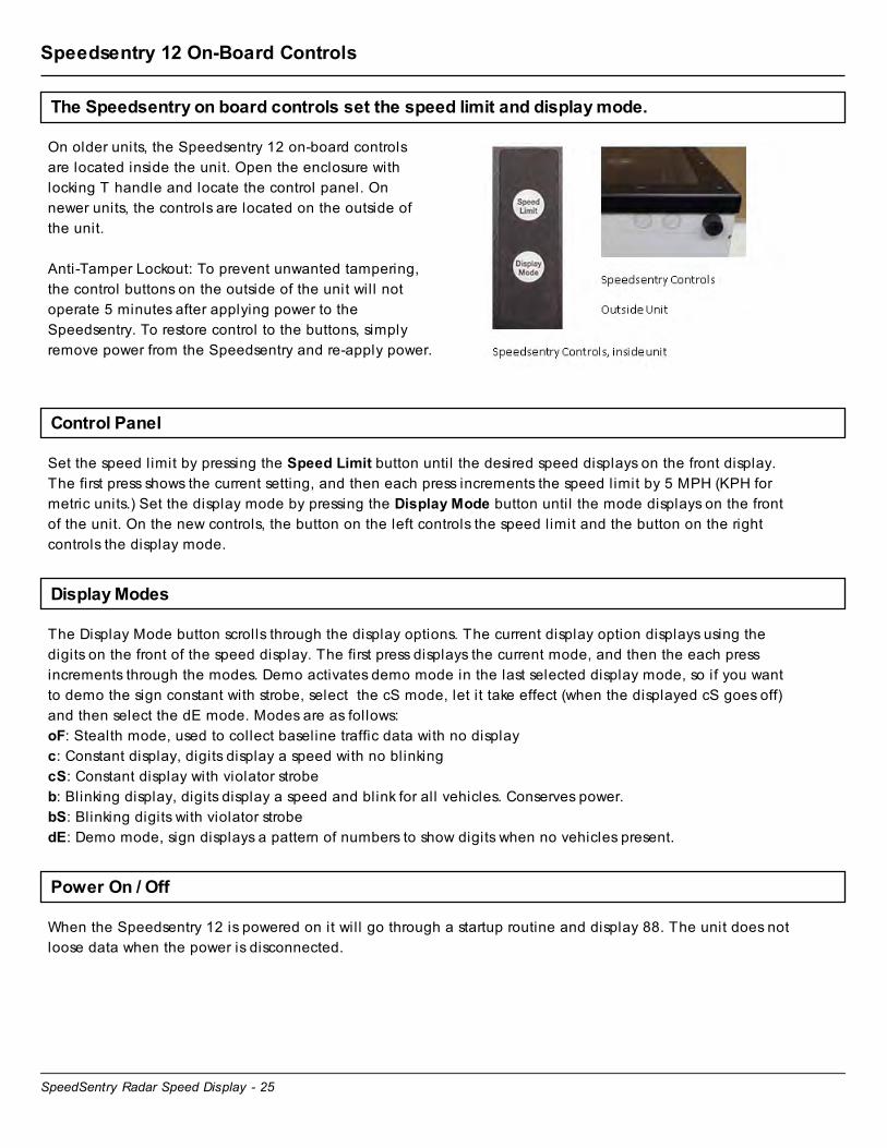
On older units, the Speedsentry 12 on-board controls
are located inside the unit. Open the enclosure with
locking T handle and locate the control panel. On
newer units, the controls are located on the outside of
the unit.
Anti-Tamper Lockout: To prevent unwanted tampering,
the control buttons on the outside of the unit wil l not
operate 5 minutes after applying power to the
Speedsentry. To restore control to the buttons, simply
remove power from the Speedsentry and re-apply power.
Control Panel
Set the speed limit by pressing the Speed Limit button until the desired speed displays on the front display.
The first press shows the current setting, and then each press increments the speed limit by 5 MPH (KPH for
metric units.) Set the display mode by pressing the Display Mode button until the mode displays on the front
of the unit. On the new controls, the button on the left controls the speed limit and the button on the right
controls the display mode.
Display Modes
The Display Mode button scrolls through the display options. The current display option displays using the
digits on the front of the speed display. The first press displays the current mode, and then the each press
increments through the modes. Demo activates demo mode in the last selected display mode, so if you want
to demo the sign constant with strobe, select the cS mode, let it take effect (when the displayed cS goes off)
and then select the dE mode. Modes are as follows:
oF: Stealth mode, used to collect baseline traffic data with no display
c: Constant display, digits display a speed with no blinking
cS: Constant display with violator strobe
b: Blinking display, digits display a speed and blink for all vehicles. Conserves power.
bS: Blinking digits with violator strobe
dE: Demo mode, sign displays a pattern of numbers to show digits when no vehicles present.
Power On / Off
When the Speedsentry 12 is powered on it will go through a startup routine and display 88. The unit does not
loose data when the power is disconnected.

SpeedSentry Radar Speed Display - 26
Move Sign Activation
When using SmartApps Remote Management, the sign
can be triggered to tell the server that is has moved. To
send the move sign signal, press both the speed limit
and the display mode buttons at the same time and
hold them for 15 seconds. The Shield will display a +
on the digits while the outer leds will circle around the
'+' to indicate that the move sign signal is being sent to
the server. Remember to reactivate the buttons if they
have timed out and stopped operating.
SpeedSentry Radar Speed Display - 27
Shield 18 On-Board Controls (Pre-2010 units)
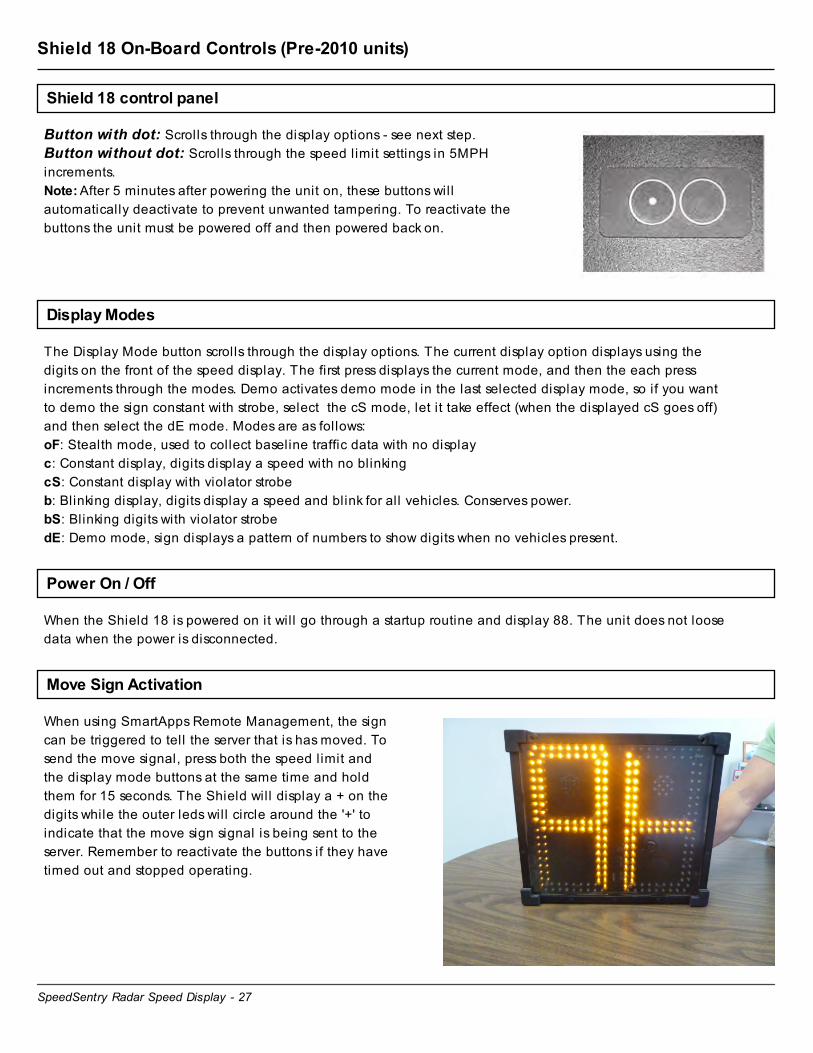
Shield 18 control panel
Button with dot: Scrolls through the display options - see next step.
Button without dot: Scrolls through the speed limit settings in 5MPH
increments.
Note: After 5 minutes after powering the unit on, these buttons will
automatically deactivate to prevent unwanted tampering. To reactivate the
buttons the unit must be powered off and then powered back on.
Display Modes
The Display Mode button scrolls through the display options. The current display option displays using the
digits on the front of the speed display. The first press displays the current mode, and then the each press
increments through the modes. Demo activates demo mode in the last selected display mode, so if you want
to demo the sign constant with strobe, select the cS mode, let it take effect (when the displayed cS goes off)
and then select the dE mode. Modes are as follows:
oF: Stealth mode, used to collect baseline traffic data with no display
c: Constant display, digits display a speed with no blinking
cS: Constant display with violator strobe
b: Blinking display, digits display a speed and blink for all vehicles. Conserves power.
bS: Blinking digits with violator strobe
dE: Demo mode, sign displays a pattern of numbers to show digits when no vehicles present.
Power On / Off
When the Shield 18 is powered on it wil l go through a startup routine and display 88. The unit does not loose
data when the power is disconnected.
Move Sign Activation
When using SmartApps Remote Management, the sign
can be triggered to tell the server that is has moved. To
send the move signal, press both the speed limit and
the display mode buttons at the same time and hold
them for 15 seconds. The Shield will display a + on the
digits while the outer leds will circle around the '+' to
indicate that the move sign signal is being sent to the
server. Remember to reactivate the buttons if they have
timed out and stopped operating.

SpeedSentry Radar Speed Display - 28
Care and Maintenance
SpeedSentry Radar Speed Display - 29
Warranty
All Traffic Solutions Warranty
All Traffic Solutions warrants this product to the original purchaser to be free of
manufacturing defects for a period of 1 year and ATS reserves the right to repair or
replace the warranted part or parts at its sole discretion. The following items are
specifically not covered under warranty.
• The warranty does not cover misuse or abuse that includes using the product in
ways for which it was not intended and vandalism.
• The warranty does not cover damage to the product due to incorrect
installation or operation nor does it cover normal wear and tear such as frayed
cords or cables, broken connectors, scratched or broken enclosures.
• This warranty does not cover batteries that are allowed to freeze.
• The warranty is void if any physical changes are made to the product by
anyone but an ATS authorized service representative.
• During the warranty period, there will be no charge for parts or labor. If
components require factory service, purchaser shall return failed parts to the
factory or authorized service location, freight prepaid. ATS will pay to return
the parts.
• If damage to the product during the warranty period is determined to be due of
a non-warranted nature, ATS reserves the right to charge for damages resulting
from abuse or extraordinary environmental damage to the product at rates
normally charged for repairing such products not covered under warranty
• ATS is not responsible for any consequential damages and as an expressed
warning, the user should be aware that harmful personal contact may be made
with the product in the event of violent maneuvers, coll isions, or other
circumstances even though the device(s) are used according to instructions.
ATS specifically disclaims any liabil ity for injury caused by the product in all
such circumstances.
All Traffic Solutions
3100 Research Drive
State College, PA 16801
www.alltrafficsolutions.com
866-366-6602

SpeedSentry Radar Speed Display - 30
Battery Maintenance and Warnings
Battery Maintenance for Lithium Ion and Lead Acid Batteries
Lead Acid Battery Maintenance
Battery maintenance: In order to maximize the life of your batteries and their abil ity to hold a charge, you
should follow several important steps in using and storing lead acid batteries
• Batteries should be placed on charge immediately after use regardless of the discharge status. Failure to
do so will shorten the battery’s l ife.
• The less the battery is drained before recharging, the longer the expected life of the battery. Charging
the battery more often, with a lower discharge, will extend its l ife.
• Whenever the batteries are not in use, even if they are mostly charged, it is always recommended to
fully charge the battery to maintain the charge and preserve the battery’s l ife. If the batteries are going
to be stored for an extended period of time, they should be fully charged before being stored and
charged up regularly (at least monthly.) Store the battery in a cool area, not directly on concrete.
• Charge the battery in a cool location. The cooler the battery is, the better it wil l charge.
• During use, keep the battery as cool as possible. This will extend the battery’s charge. If you have a
choice between a shaded location and a direct sun location, choose the shade if practical. This is not
possible if using a solar panel.
• To recharge the batteries, plug a 120V extension cord into the plug in the side of the battery box. This
will charge all the enclosed batteries. The display on the installed battery charger will indicate when the
batteries are fully charged. Use of any battery charger other than the unit supplied will void the warranty.
• In the winter, it is important that the batteries are protected from freezing. It is best to store the
batteries where there is no chance of freezing. If this is not possible, keep the batteries charged while in
storage. A fully charged battery can resist freezing better than one with a low charge. If the trailer is to
be stored inside and the solar panel will not be able to maintain the charge on the system it is necessary
to charge the batteries regularly. Batteries that are allowed to freeze are not cov ered under warranty.
• If your trailer is equipped with a solar panel, the panel should always be connected to the solar
controller, which will allow the batteries to remain fully charged whenever the trailer is in transit or in
storage outdoors. Keep the solar panel clean for optimal charging.
• If flooded trailer batteries are removed from the battery box, they must be stored upright.
• For flooded trailer batteries, check the battery water level when charging. If it is low, fi l l using distilled
water only.
• Clean excessive corrosion on the terminals with a mixture of baking soda and water. Make sure battery
terminals are tight.
• To test the charger: Measure the voltage on the batteries. Plug in the charger and the voltage should go
higher.
• To test the solar panel: On a sunny day, check the voltage on the solar connection on the solar
controller. It should be higher than the voltage on the batteries.
Lead Acid Battery Warnings
Lead based batteries can be dangerous. Note the following precautions:
• Always charge batteries in a v entilated area.
• Nev er smoke or allow a spark or fire in the v icinity of a charging battery.
• The batteries should only be charged w ith the prov ided automatic charger to prev ent ov ercharging.
The display on the battery charger will indicate when the batteries are fully charged. Use of any

SpeedSentry Radar Speed Display - 31
battery charger other than the unit supplied will v oid the warranty.
• Do not use the charger if any of the cords or electrical connections on the charger or battery are
damaged. Contact ATS for replacement of damaged parts.
• Nev er try to charge a battery with any physical damage.
• Be careful of shorting the terminals of the battery inadv ertently with a tool, jewelry or any other
conductiv e item. Shorting the terminals could cause the battery to explode.
• Monitor charger and battery frequently during charging to make sure both are functioning properly.
• Do not allow the batteries to freeze. Batteries that hav e been frozen are not cov ered under warranty.
• Nev er attempt to charge a frozen battery.


