TECHNICAL PAPER - CA Traffic · IN043 Advanced BlackCAT Radar Technical document 24/05/16 IN043...
5
Black CAT Radar TECHNICAL PAPER
Transcript of TECHNICAL PAPER - CA Traffic · IN043 Advanced BlackCAT Radar Technical document 24/05/16 IN043...

Black CAT Radar
TECHNICALPAPER
IN043 Advanced BlackCAT Radar Technical document 24/05/16 IN043 Advanced BlackCAT Radar Technical document 24/05/16
Advanced BlackCAT Radar Statistics – 2016 Advanced BlackCAT Radar Statistics – 2016
IntroductionWith the advancements of the CA Traffic BlackCAT Radar, which utilises the latest radar technology,it is now possible to detect and record two individual lanes of traffic travelling in the same direction, for example half a dual carriageway with an individual channel per lane.
In light of this we feel it’s important to measure the performance against a conventional inductive loop site. There are almost always obscuration issues when dealing with Radar Outstations due to high sided near side traffic, however thanks to state-of-the-art platoon splitting algorithms the majority of far side traffic can now be correctly resolved.
Due to the advances in technology and hardware developments for dual carriageway operation, the BlackCAT Radar has also inherited advanced single carriageway performance.
HistoryCA Traffic have been developing traffic monitoring instruments for over 20 years, ranging frominductive loop recorders to ANPR cameras.
The BlackCAT family is an intelligent traffic counter platform combining all of the functionality of CA Traffic’s traditional counter classifiers in to a flexible, modular design with vastly improved specification and functionalty.
Our inhouse developers have combined years of experience to bring the market a counter with added value, which meets the advanced needs of today’s market whilst considering tomorrow’s technology.
The BlackCAT inductive loop recorders, boast a proven volumetric accuracy of 99.5% with a 95%confidence, providing the perfect base for like-for-like comparisons against the BlackCAT Radar in real world situations.
Advanced DeploymentUtilising the BlackCAT family technology, the Radar now has advanced communication and surveyoptions. As well as being battery powered for standalone surveys it is now possible for Radar sites to be permanently deployed when powered by solar or mains supply. CA Traffic have developed a solution to allow this hardware to be mounted to existing street furniture or dedicated pole installations.
The solar solution enables real time communications and data transfer to an in-station over GSM, GPRS or 3G indefinitely. This means the technology can be used for live UTMC systems where it’s not possible or feasible to install loops in the road. Speed and flow threshold algorithms are built in to trigger alerts if required, providing the same functionality as the BlackCAT loop based equipment.
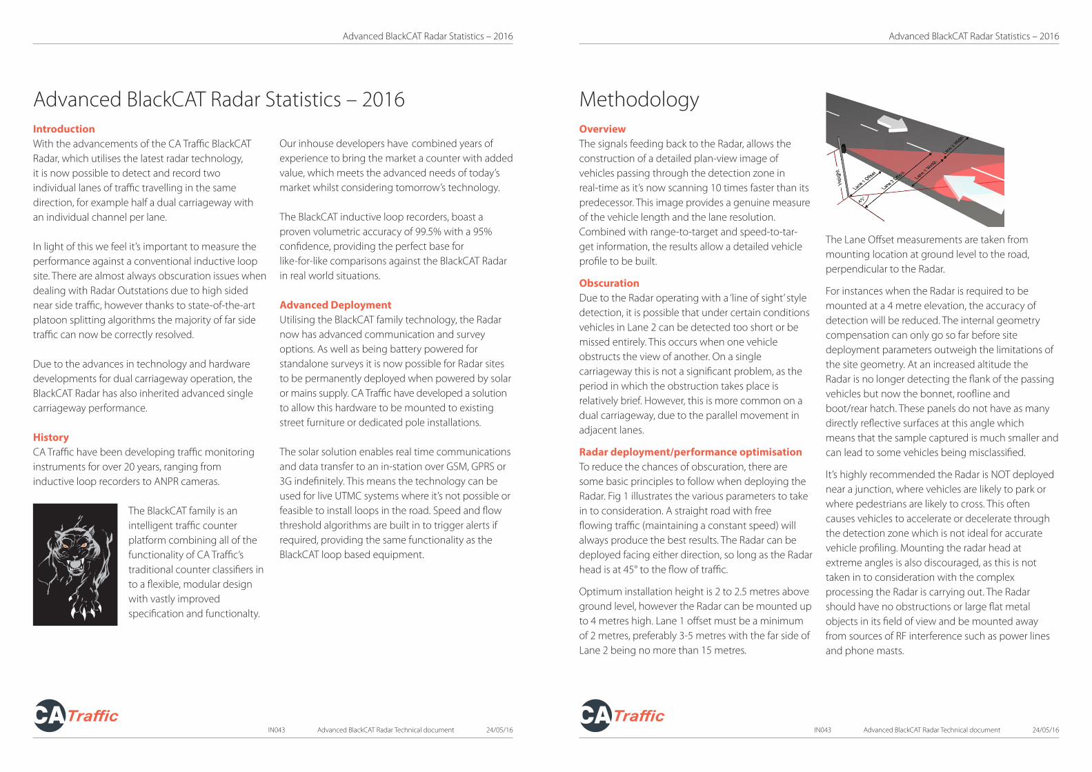
Advanced BlackCAT Radar Statistics – 2016OverviewThe signals feeding back to the Radar, allows theconstruction of a detailed plan-view image of vehicles passing through the detection zone in real-time as it’s now scanning 10 times faster than its predecessor. This image provides a genuine measure of the vehicle length and the lane resolution. Combined with range-to-target and speed-to-tar-get information, the results allow a detailed vehicle profile to be built.
ObscurationDue to the Radar operating with a ‘line of sight’ styledetection, it is possible that under certain conditionsvehicles in Lane 2 can be detected too short or be missed entirely. This occurs when one vehicleobstructs the view of another. On a single carriageway this is not a significant problem, as the period in which the obstruction takes place is relatively brief. However, this is more common on a dual carriageway, due to the parallel movement in adjacent lanes.
Radar deployment/performance optimisationTo reduce the chances of obscuration, there are some basic principles to follow when deploying theRadar. Fig 1 illustrates the various parameters to take in to consideration. A straight road with freeflowing traffic (maintaining a constant speed) will always produce the best results. The Radar can bedeployed facing either direction, so long as the Radar head is at 45° to the flow of traffic.
Optimum installation height is 2 to 2.5 metres above ground level, however the Radar can be mounted up to 4 metres high. Lane 1 offset must be a minimum of 2 metres, preferably 3-5 metres with the far side of Lane 2 being no more than 15 metres.
The Lane Offset measurements are taken from mounting location at ground level to the road, perpendicular to the Radar.
For instances when the Radar is required to be mounted at a 4 metre elevation, the accuracy ofdetection will be reduced. The internal geometry compensation can only go so far before sitedeployment parameters outweigh the limitations of the site geometry. At an increased altitude theRadar is no longer detecting the flank of the passing vehicles but now the bonnet, roofline andboot/rear hatch. These panels do not have as many directly reflective surfaces at this angle whichmeans that the sample captured is much smaller and can lead to some vehicles being misclassified.
It’s highly recommended the Radar is NOT deployed near a junction, where vehicles are likely to park or where pedestrians are likely to cross. This often causes vehicles to accelerate or decelerate through the detection zone which is not ideal for accurate vehicle profiling. Mounting the radar head at extreme angles is also discouraged, as this is not taken in to consideration with the complexprocessing the Radar is carrying out. The Radar should have no obstructions or large flat metalobjects in its field of view and be mounted away from sources of RF interference such as power linesand phone masts.
Methodology

ResultsVolumetric CountsBelow are graphs depicting a comparison of vehicle counts between a BlackCAT Radar and BlackCATinductive loop system on a dual carriageway, detecting individual lanes of traffic.
Results: As shown, in both cases volumetric counts between the two differing technologies were virtually identical for Lane 1. Where the detections drop slightly for the Radar in Lane 2, for both styles of deployment, this clearly illustrates the effect of obscuration. As noted previously, this limitation of the geometry is accentuated on dual carriageway deployment, especially during peak traffic times. However despite this, we are still able to produce a high level of count accuracy.
A41 Bidirectional Comparision of BlackCAT Radar and BlackCAT Loop Unit
A442 Dual Carriageway Comparison of BlackCat Radar and BlackCat Loop Units
Advanced BlackCAT Radar Statistics – 2016
IN043 Advanced BlackCAT Radar Technical document 24/05/16 IN043 Advanced BlackCAT Radar Technical document 24/05/16
Advanced BlackCAT Radar Statistics – 2016
Speed measurementsBelow are graphs depicting a comparison of measured vehicle speeds between a BlackCAT Radar and BlackCAT inductive loop system on a dual carriageway, detecting both lanes of traffic, and on a single carriageway, reading bidirectional traffic.
Results: The speed data from both types of deployment is very accurate. The speed detection on the dual carriageway that has been captured shows that the site is very free flowing with a much higher average speed. Traffic speeds in the nearside lane is also consistently lower as you would expect for these types of road. Most importantly however, the traffic is well disciplined and consistent when passing through the detection zone, giving a very clean signal for the Radar to process which in turn produces a very high level of accuracy.
The single carraigeway site clearly portrays AM and PM peaks and a drop in average speeds during these times of congestion. Traffic during times of congestion often leads to the increase and decrease of the speed of traffic through the zone of dection, which can compromise of speed data reported as the Radar has to resolve the speed against the varying samples of data it collects.
A41 Speed Comparision of BlackCAT Radar and BlackCAT Loop Unit
A422 Speed Comparision of BlackCAT Radar and BlackCAT Loop Unit

IN043 Advanced BlackCAT Radar Technical document 24/05/16 IN043 Advanced BlackCAT Radar Technical document 24/05/16
Advanced BlackCAT Radar Statistics – 2016 Advanced BlackCAT Radar Statistics – 2016
Length measurementsBelow are graphs comparing the measured vehicle lengths between the Black CAT radar and Black CAT Inductive Loop system. In this instance multiple graphs are displayed for the various vehicle types, this first set being on a bidirectional carriageway.
A41 Length Comparision of BlackCAT Radar andBlackCAT Loop Unit (Cars)
A41 Length Comparision of BlackCAT Radar andBlackCAT Loop Unit (Trucks)
A41 Length Comparision of BlackCAT Radar andBlackCAT Loop Unit (Articulated Trucks)
A422 Length Comparision of BlackCAT Radar andBlackCAT Loop Unit (Cars)
A422 Length Comparision of BlackCAT Radar andBlackCAT Loop Unit (Trucks)
A422 Length Comparision of BlackCAT Radar andBlackCAT Loop Unit (Articulated Trucks)
Results: The length data produced from the comparison survey has been split in to 3 bins of vehicle type. Cars, Trucksand Articulated Trucks. For both styles of deployment the Car bin shows very closely matched data, this is primerily due to the fact that this type of traffic makes up on average 80% of the vehicles on the road but also because the larger vehicles tend to be in the zone of detection for longer, there is a higher chance for obscuration, which may cause these vehicles to be split in to smaller vehicles, hence the results for the Trucks and Articulated Trucks don’t tend to be as smooth. The platoon splitting algorithm will resolve as many of these scenarios as possible, but there are limitions depending on how heavily congested the road is.
Next we have a dual carriageway deployment using the same hardware.
Advanced BlackCAT Radar Statistics – 2016
T: +44(0) 1296 333499 E: [email protected] W: www.ca-traffic.com
Deployment: Install height – 2 to 4 metres* Offset to nearside lane – minimum 2 metres Maximum detection range – 15 metres
*2-2.5 metres ideal installation height
Comms Options: Local USB / Local Bluetooth / GSM Telemetry / GPRS / 3G
Power Supply: 12v 12Ah Battery supply. 7 days operation (with no power saving)
12v 18Ah Battery supply 12 days operation (with no power saving) Solar – 40w panel recommended for use with Real-Time comms Continuous operation
240v Mains Continuous operation Statistics:
Statistics calculated against inductive loop results
Bi-directional Traffic
Volume 98% accuracy with a 95% confidence
Speed +/- 2mph or 3% whichever is greater with a 95% confidence
Length +/- 40cm or 5% whichever is greater with a 95% confidence
Dual Carriageway Traffic
Volume 97% accuracy with a 95% confidence
Speed +/- 2mph or 3% whichever is greater with a 97% confidence
Length +/- 40cm or 5% whichever is greater with a 95% confidence
Conclusion:There are obvious characteristics and traits to both styles of deployment which is why the statistics below are noted individually. The changes in performance also give clear indicators to the conditions that the Radar produces thebest results. These situations should be taken in to consideration when deciding on where to carry out your surveys to ensure the best quality results.
Free flowing, consistent and well-disciplined traffic on a road with no obstructions, junctions or bends that allows the Radar to be mounted 2-3m back from the curb with an installation height of 2-2.5m and 45° to the flow of traffic, are the recommended site conditions, however the Radar runs intelligent algorithms to accurately detect vehicles in many other deployment conditions.
+44(0) 1296 333499 [email protected] www.ca-traffic.com
IN043 Advanced BlackCAT Radar Technical document 24/05/16