Spectroscopy Introduction and Applications - Home - …€¦ · · 2018-01-16Spectroscopy...
62
August 18, 2015 Spectroscopy Introduction and Applications A Guide for Use with Ocean Optics OceanView Software
Transcript of Spectroscopy Introduction and Applications - Home - …€¦ · · 2018-01-16Spectroscopy...

August 18, 2015
Spectroscopy Introduction andApplications
A Guide for Use with Ocean Optics OceanView Software
2
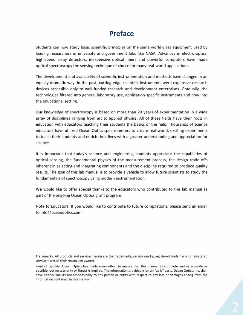
PrefaceStudents can now study basic scientific principles on the same world-class equipment used byleading researchers in university and government labs like NASA. Advances in electro-optics,high-speed array detectors, inexpensive optical fibers and powerful computers have madeoptical spectroscopy the sensing technique of choice for many real-world applications.
The development and availability of scientific instrumentation and methods have changed in anequally dramatic way. In the past, cutting-edge scientific instruments were expensive researchdevices accessible only to well-funded research and development enterprises. Gradually, thetechnologies filtered into general laboratory use, application-specific instruments and now intothe educational setting.
Our knowledge of spectroscopy is based on more than 20 years of experimentation in a widearray of disciplines ranging from art to applied physics. All of these fields have their roots ineducation with educators teaching their students the basics of the field. Thousands of scienceeducators have utilized Ocean Optics spectrometers to create real-world, exciting experimentsto teach their students and enrich their lives with a greater understanding and appreciation forscience.
It is important that today's science and engineering students appreciate the capabilities ofoptical sensing, the fundamental physics of the measurement process, the design trade-offsinherent in selecting and integrating components and the discipline required to produce qualityresults. The goal of this lab manual is to provide a vehicle to allow future scientists to study thefundamentals of spectroscopy using modern instrumentation.
We would like to offer special thanks to the educators who contributed to this lab manual aspart of the ongoing Ocean Optics grant program.
Note to Educators: If you would like to contribute to future compilations, please send an emailto [email protected].
Trademarks: All products and services herein are the trademarks, service marks, registered trademarks or registeredservice marks of their respective owners.Limit of Liability: Ocean Optics has made every effort to ensure that this manual as complete and as accurate aspossible, but no warranty or fitness is implied. The information provided is on an “as is” basis. Ocean Optics, Inc. shallhave neither liability nor responsibility to any person or entity with respect to any loss or damages arising from theinformation contained in this manual.
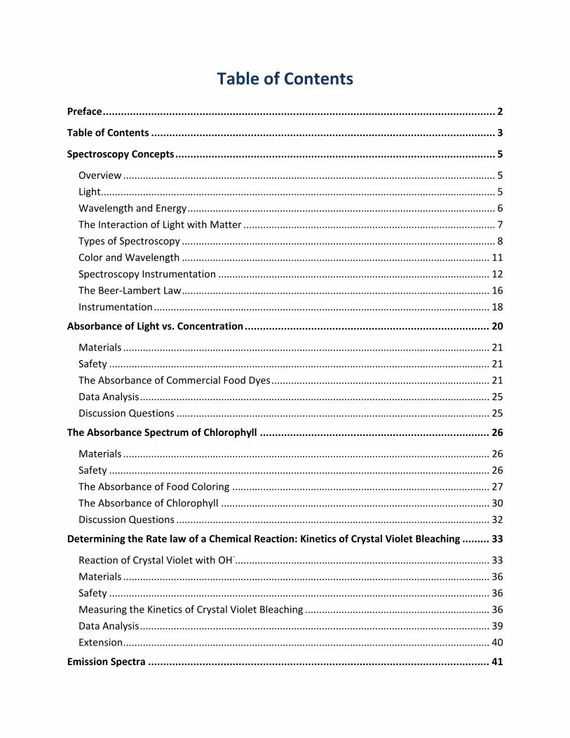
Table of Contents
Preface.................................................................................................................................. 2
Table of Contents .................................................................................................................. 3
Spectroscopy Concepts.......................................................................................................... 5
Overview ..................................................................................................................................... 5Light............................................................................................................................................. 5Wavelength and Energy.............................................................................................................. 6The Interaction of Light with Matter .......................................................................................... 7Types of Spectroscopy ................................................................................................................ 8Color and Wavelength .............................................................................................................. 11Spectroscopy Instrumentation ................................................................................................. 12The Beer-Lambert Law.............................................................................................................. 16Instrumentation........................................................................................................................ 18
Absorbance of Light vs. Concentration ................................................................................. 20
Materials ................................................................................................................................... 21Safety ........................................................................................................................................ 21The Absorbance of Commercial Food Dyes.............................................................................. 21Data Analysis............................................................................................................................. 25Discussion Questions ................................................................................................................ 25
The Absorbance Spectrum of Chlorophyll ............................................................................ 26
Materials ................................................................................................................................... 26Safety ........................................................................................................................................ 26The Absorbance of Food Coloring ............................................................................................ 27The Absorbance of Chlorophyll ................................................................................................ 30Discussion Questions ................................................................................................................ 32
Determining the Rate law of a Chemical Reaction: Kinetics of Crystal Violet Bleaching ......... 33
Reaction of Crystal Violet with OH-........................................................................................... 33Materials ................................................................................................................................... 36Safety ........................................................................................................................................ 36Measuring the Kinetics of Crystal Violet Bleaching .................................................................. 36Data Analysis............................................................................................................................. 39Extension................................................................................................................................... 40
Emission Spectra ................................................................................................................. 41
4
Materials ................................................................................................................................... 41Safety ........................................................................................................................................ 41Measuring Light Source Emission with a Spectrometer ........................................................... 42Data Analysis............................................................................................................................. 44
Spectrophotometric Analysis of Commercial Aspirin ............................................................ 45
Prelab Questions....................................................................................................................... 47Materials ................................................................................................................................... 48Safety ........................................................................................................................................ 48Hydrolyzing the ASA and Aspirin samples ................................................................................ 48Data Sheet 1.............................................................................................................................. 54Data Sheet 2.............................................................................................................................. 55Calculations............................................................................................................................... 56Post Lab Questions ................................................................................................................... 57
Spectrophotometric Characterization of Spice Extracts ........................................................ 58
Materials ................................................................................................................................... 58Safety ........................................................................................................................................ 58Procedure.................................................................................................................................. 59Data and Analysis...................................................................................................................... 62
5
Spectroscopy Concepts
Overview
Scientific discoveries are based on observations. Scientists look for patterns in what they see,hear, feel, smell and taste to formulate theories and make predictions. Originally, scientistsdepended solely on their own senses to make observations. But as science has evolved,scientists have developed instruments to extend their observational powers beyond oursensory limits. Telescopes have enabled astronomers to see more of the sky and vastly improveour understanding of the heavens. Likewise, microscopes have enabled biologists to view eversmaller parts of living organisms in their quest to understand living systems.
Astronomers are only limited by the size of the telescopes they can build and the distortingeffects of the earth's atmosphere. As technological developments have allowed for biggermirrors and space-based platforms, astronomers have been able to see ever further into spaceand make more and more discoveries. Unfortunately, the situation is very different going in theother direction. There is a physical limit to the size of objects that can be "seen." This limit isdue to the nature of light itself.
Light
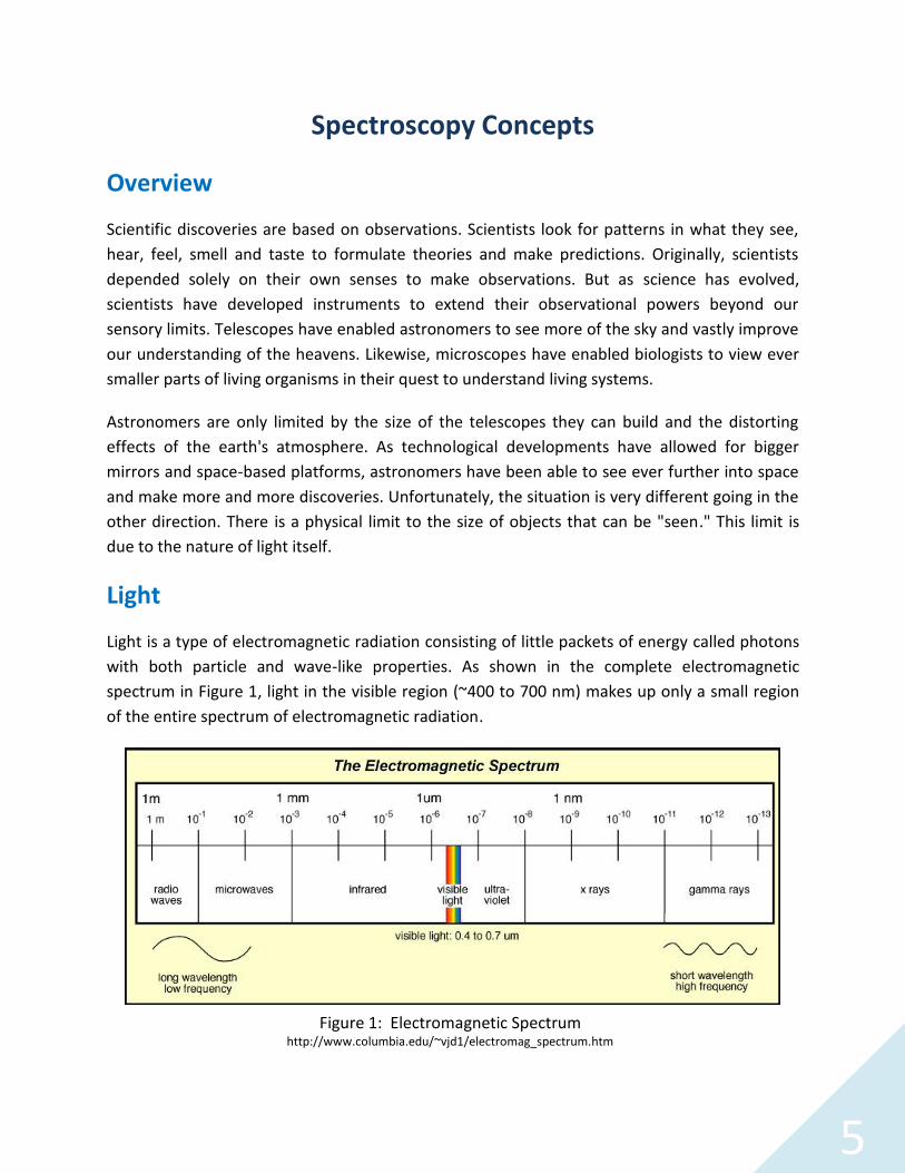
Light is a type of electromagnetic radiation consisting of little packets of energy called photonswith both particle and wave-like properties. As shown in the complete electromagneticspectrum in Figure 1, light in the visible region (~400 to 700 nm) makes up only a small regionof the entire spectrum of electromagnetic radiation.
Figure 1: Electromagnetic Spectrumhttp://www.columbia.edu/~vjd1/electromag_spectrum.htm
6
It is the wave properties of light that limit our ability to use light to create images. For any givenwavelength, images can be formed for objects larger than the wavelength of light used tovisualize the image. Therefore, for visible light (wavelengths between 4 x 10⁻⁷ and 7 x 10⁻⁷ m) itis impossible to form images of atoms with sizes on the order of 10-9 m. Very large molecularassemblies such as chromosomes (DNA molecules coated with protein molecules) are thesmallest objects we can image with visible light.
The challenge faced by chemists, biochemists and microbiologists is studying what happens atthe atomic and molecular level without actually being able to physically visualize atoms andmolecules. Fortunately, even though we cannot capture images of atoms and molecules, wecan use light to learn more about them. This is because atoms and molecules interact with lightproviding detailed information on their structure, composition and interactions. The techniquefor measuring the interaction of light with matter is referred to as spectroscopy. It is arguablythe most powerful tool available to scientists to study the molecular world around them.Spectroscopy techniques are used universally in science at the intersection of the disciplines ofchemistry, biology, engineering and physics.
Wavelength and Energy
Our understanding of the nature of light is a relatively recent development. For a long time thedifferent forms of electromagnetic radiation were thought to be individual phenomena. Thus,we have the collection of common names ending in -wave and –ray for the various wavelengthranges. This is because the energy of a photon is inversely related to its wavelength. Theshorter the wavelength, the higher the energy of the photon.
Where:
E = Energy of the photon in joulesλ = Wavelength in nanometersh = Planck's constantc = Speed of light
The enormous wavelength range for known electromagnetic radiation yields photons withenergy covering an equally wide range. It is this energy that determines the effect of thephoton when it interacts with matter. For example, radio frequency photons have very smallenergies enabling us to saturate our atmosphere with them without affecting our environment.The amount of energy they impart to whatever absorbs them is almost negligible (you don’t getdents in your car from listening to one of the many available radio stations). Infrared photonshave enough energy to heat objects and, as a result, they make great heat lamps. Ultravioletphotons have enough energy to break chemical bonds and can cause molecular
7
rearrangements resulting in effects like sunburn and genetic damage. X-rays are very energeticand readily break even the strongest bonds causing significant molecular destruction. For thisreason the medical use of X-rays is destructive of living tissues and must be done carefully andonly in extremely small doses.
The Interaction of Light with Matter
It is the electrons in atoms and molecules that typically absorb and emit photons of light. It isworth noting that gamma rays are energetic enough to interact with atomic nuclei andgenerate photons of light, but we'll leave that to the physicists to pursue. When an electronabsorbs low energy photons, like radio frequencies, the “spin” of the electron is flipped. Thiseffect is used in nuclear magnetic resonance spectroscopy (NMR) and can also be used togenerate the images from magnetic resonance imaging (MRI). When an electron absorbsinfrared, visible and ultraviolet photons they change energy level. All electrons have a series ofenergy levels they can occupy. The lowest energy level is referred to as the "ground state." Thehighest level is the "ionization energy" or the energy required to completely remove theelectron from the influence of the nucleus. In order for an electron to move from one level to ahigher level it must absorb energy equal to the difference in the levels. Likewise, to move to alower level the electron must give up energy equal to the difference. Because there are alimited number of levels the electron can occupy, there are limited amounts of energy it canabsorb or give up.
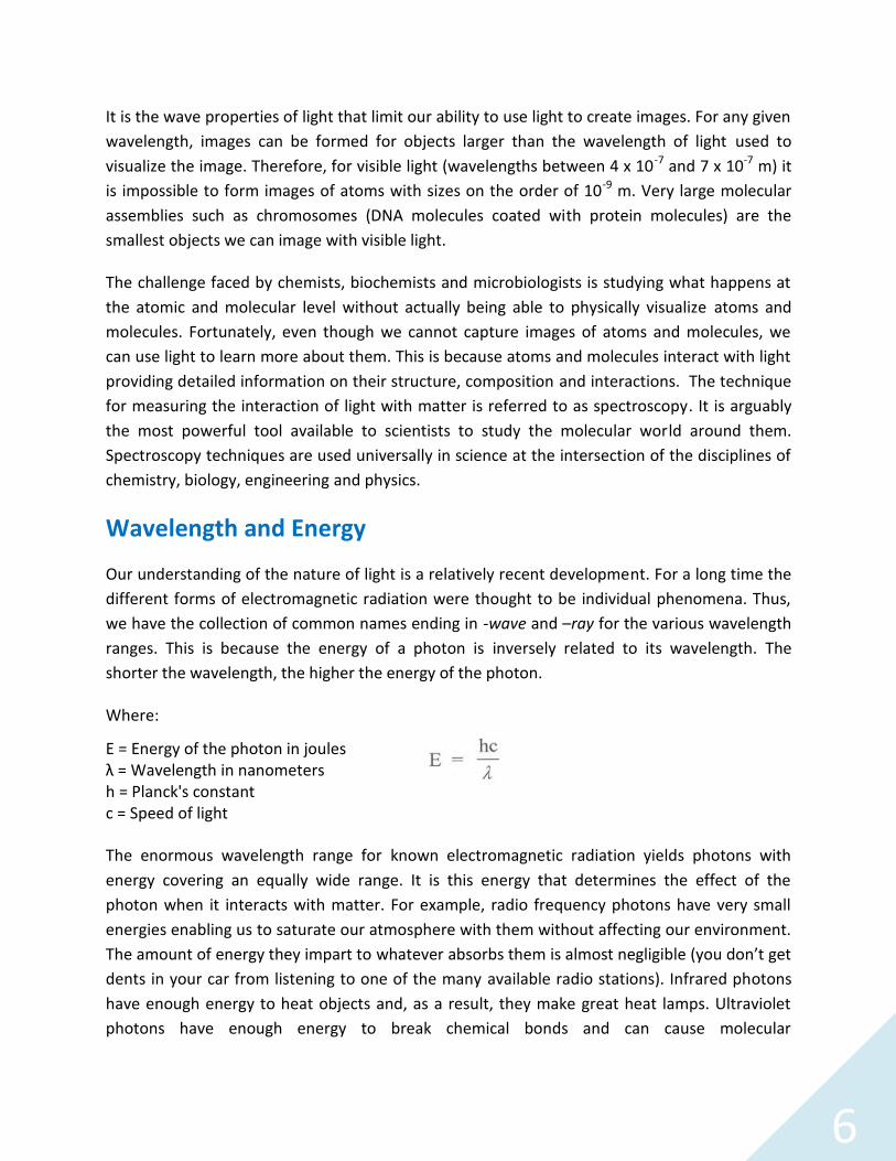
A more detailed discussion can be found in Chemistry andChemical Reactivity, Chapter 7 by Kotz and Treichel. Their figure7.13 is a detailed presentation of the electronic transitionspossible for the simplest atom, the hydrogen atom. Figure 2 is adiagram of the most common transitions possible for a sodiumatom. The 3s to 4p transition is in the ultraviolet range. The 3pto 3d transition is in the infrared range. And the 3s to 3ptransition is in the orange region of the visible spectrum. Thisline is the source of the characteristic color of sodium vaporlamps.
There are a number of ways an electron can gain or lose energy.The ones of interest here are the absorption or emission of light.An electron can absorb a photon of light that strikes it only ifthat photon has the exact energy to change the electron to ahigher allowed energy level. An electron already at a higher levelcan emit a photon of light having exactly enough energy to
Figure 2: CommonElectronic Transitions for
Sodium
8
change that electron to one of its lower allowed levels. Note that an electron in the groundstate cannot emit any photons as it already has the lowest possible energy.
The magnitude of the difference in allowed energy levels determines which kinds of light can beused to study particular atoms and molecules. While spectroscopy is conducted in nearly allregions of the electromagnetic spectrum, practical considerations make the infrared, visible andultraviolet regions the most useful in chemical laboratories.
Infrared spectroscopy is particularly useful for studying the vibration of bonds between carbon,hydrogen, oxygen and nitrogen atoms that predominate in organic compounds. Thus, infraredspectroscopy is a key tool of the organic chemist. Infrared spectra can indicate the presence ofparticular functional groups in unknown organic compounds by the presence of characteristicfeatures. They can also be used to confirm the identity of compounds by comparison withknown spectra. Reference books containing thousands of spectra of known organic compoundsare available for this purpose.
Visible light spectroscopy is useful for studying some organic compounds and elements thathave electrons in d-orbitals, such as transition metals.
Ultraviolet spectroscopy is useful for studying some organic compounds and most biologicalsamples. All proteins have useful ultraviolet spectra as do nucleic acids. Furthermore, UVspectroscopy can be used to follow biochemical reactions and this tool is commonly found inbiochemical laboratories. In clinical laboratories, ultraviolet spectroscopy is often the means formaking quantitative determinations on plasma and urine samples.
Types of Spectroscopy
Spectroscopy is the study of the interaction of light with matter. There are two distinct aspectsof this interaction that can be used to learn about atoms and molecules. One is theidentification of the specific wavelengths of light that interact with the atoms and molecules.The other is the measurement of the amount of light absorbed or emitted at specificwavelengths. Both determinations require separating a light source into its componentwavelengths. Thus, a critical component of any spectroscopic measurement is breaking up oflight into a spectrum showing the interaction of light with the sample at each wavelength.
Light interacts with matter in many ways. Two of the most common interactions are light that isabsorbed by the atoms and molecules in the sample and light that is emitted after interactingwith the atoms and molecules in the sample.
9
Absorption Spectroscopy
Absorption spectroscopy is the study of light absorbed by molecules. For absorbancemeasurements, white light is passed through a sample and then through a device (such as aprism) that breaks the light up into its component parts or a spectrum. White light is a mixtureof all the wavelengths of visible light. When white light is passed through a sample, under theright conditions, the electrons of the sample absorb some wavelengths of light. This light isabsorbed by the electrons so the light coming out of the sample will be missing thosewavelengths corresponding to the energy levels of the electrons in the sample. The result is aspectrum with black lines at the wavelengths where the absorbed light would have been if ithad not been removed by the sample.
Emission Spectroscopy
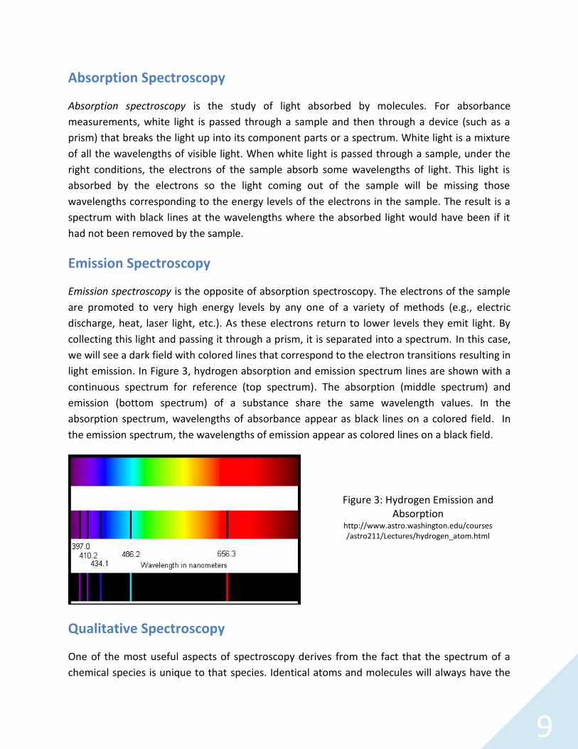
Emission spectroscopy is the opposite of absorption spectroscopy. The electrons of the sampleare promoted to very high energy levels by any one of a variety of methods (e.g., electricdischarge, heat, laser light, etc.). As these electrons return to lower levels they emit light. Bycollecting this light and passing it through a prism, it is separated into a spectrum. In this case,we will see a dark field with colored lines that correspond to the electron transitions resulting inlight emission. In Figure 3, hydrogen absorption and emission spectrum lines are shown with acontinuous spectrum for reference (top spectrum). The absorption (middle spectrum) andemission (bottom spectrum) of a substance share the same wavelength values. In theabsorption spectrum, wavelengths of absorbance appear as black lines on a colored field. Inthe emission spectrum, the wavelengths of emission appear as colored lines on a black field.
Qualitative Spectroscopy
One of the most useful aspects of spectroscopy derives from the fact that the spectrum of achemical species is unique to that species. Identical atoms and molecules will always have the
Figure 3: Hydrogen Emission andAbsorption
http://www.astro.washington.edu/courses/astro211/Lectures/hydrogen_atom.html

10
same spectra. Different species will have different spectra. For this reason, the spectrum of aspecies can be thought of as a fingerprint for that species. Qualitative spectroscopy is used toidentify chemical species by measuring a spectrum and comparing it with spectra for knownchemical species to find a match.
As an example, consider the discovery of the element helium. It was first observed, not on theearth, but in the sun! In 1868 the French astronomer, Pierre Jules César Janssen, was in India toobserve a solar eclipse when he detected new lines in the solar spectrum. No element known atthat time would produce these lines and so he concluded that the sun contained a newelement. This initiated a search for the new element on planet earth. By the end of thatcentury, the new element had been identified in uranium ores and was named helium after theGreek word for the sun (Helios). Today, spectroscopy finds wide application in the identificationof chemical species.
Quantitative Spectroscopy
Quantitative spectroscopy is one of the quickest and easiest ways to determine how manyatoms or molecules are present in a sample. This is because the interaction of light with matteris a stoichiometric interaction. At any given temperature, the same number of photons willalways be absorbed or emitted by the same number of atoms or molecules in a given period oftime. This makes spectroscopy one of the few techniques that can provide a direct measure ofthe number of atoms or molecules present in a sample.
Quantitative emission spectroscopy requires heating samples to very high temperatures toenable electrons to emit light. Most often, this is done by feeding the sample into a burnerflame. As a result, it is not practical for use with most molecular compounds but is frequentlyemployed for elemental analysis.
Absorption spectroscopy is performed by passing light of all wavelengths through a sample andmeasuring how much of the light at each wavelength is absorbed. The statement made abovethat "the absorption spectrum will appear as black lines on a colored field" is a considerableoversimplification. The interactions of atoms and molecules with water molecules make theabsorbance of light in solutions a very complex phenomenon. Nevertheless, the patterns arerepeatable and predictable, thus making them useful. By making absorbance measurements atvarious wavelengths and then plotting the result, one can create what is known as anabsorbance spectrum.

11
In Figure 4 the absorbance spectra for differentheme-containing proteins is shown. Eventhough the proteins are closely related, theabsorbance spectra are distinct enough toenable discrimination of the different proteins.Absorbance spectra are like fingerprints. Eachcompound has its own unique spectrum. Insome cases the spectrum can be used toidentify the presence of certain compounds ina sample. More often, it is used to determinethe amount of a compound present.
Due to the nature of the electronic changes that give rise to absorption spectra, the peaks aregenerally broad. Therefore, absorption spectroscopy is less useful than other moleculartechniques for the purpose of identifying compounds. For example, infrared or Ramanspectroscopy is much better for identifying the component species when compared to UV-Visible absorption spectroscopy.
Color and Wavelength
The visible region is a good place to begin a discussion of spectroscopy because color vision is acritical feature of our everyday world. Our perception of color is the eye's response to light ofdifferent wavelengths. When photons of a narrow wavelength range interact with our retina,we perceive the effect as color. The apparent color of an object is due to the wavelengths ofthe photons of light reaching our eyes from that object. This is true whether the object isemitting its own light or reflecting light from another source. In a sense, our eyes operate like aspectrophotometer.
White light is a mixture of light of all wavelengths (colors). When white light strikes an objectand is completely reflected, we see equal amounts of light of all colors and perceive the objectto be white. When all light striking an object is absorbed, no light enters our eyes and weperceive the object to be black. A sheet of paper is white because all light striking it is reflectedand none is absorbed. The print on the paper is black because all light striking it is absorbed.None is reflected. We perceive color when some wavelengths of light are reflected (ortransmitted in the case of a solution) more than others.
There is a rather complex pattern to the absorption of light by colored objects. The statementthat "an object appears red because all red light is reflected and all other light is absorbed" is aconsiderable oversimplification. In fact, varying amounts of light of different wavelengths are
Figure 4: UV-Vis Absorbance Spectra forHeme Proteins
12
absorbed in most colored objects and the color we perceive is more closely related to the colorthat is most absorbed rather than to the color that is reflected.
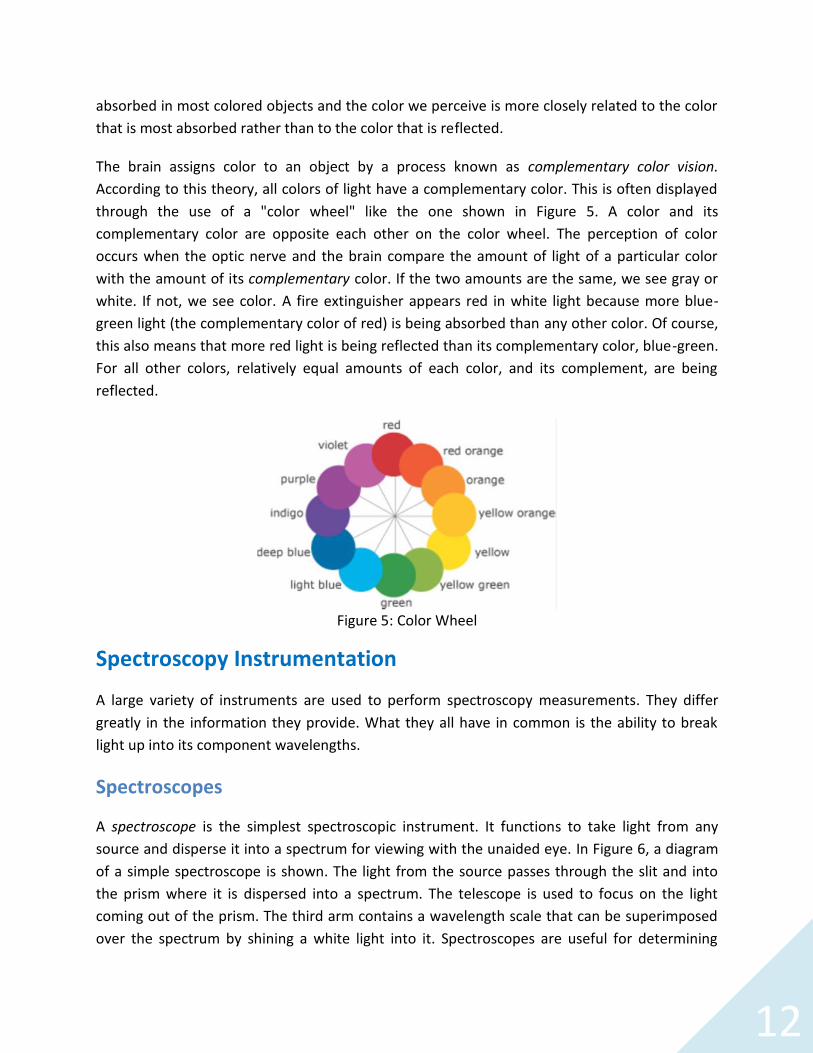
The brain assigns color to an object by a process known as complementary color vision.According to this theory, all colors of light have a complementary color. This is often displayedthrough the use of a "color wheel" like the one shown in Figure 5. A color and itscomplementary color are opposite each other on the color wheel. The perception of coloroccurs when the optic nerve and the brain compare the amount of light of a particular colorwith the amount of its complementary color. If the two amounts are the same, we see gray orwhite. If not, we see color. A fire extinguisher appears red in white light because more blue-green light (the complementary color of red) is being absorbed than any other color. Of course,this also means that more red light is being reflected than its complementary color, blue-green.For all other colors, relatively equal amounts of each color, and its complement, are beingreflected.
Figure 5: Color Wheel
Spectroscopy Instrumentation
A large variety of instruments are used to perform spectroscopy measurements. They differgreatly in the information they provide. What they all have in common is the ability to breaklight up into its component wavelengths.
Spectroscopes
A spectroscope is the simplest spectroscopic instrument. It functions to take light from anysource and disperse it into a spectrum for viewing with the unaided eye. In Figure 6, a diagramof a simple spectroscope is shown. The light from the source passes through the slit and intothe prism where it is dispersed into a spectrum. The telescope is used to focus on the lightcoming out of the prism. The third arm contains a wavelength scale that can be superimposedover the spectrum by shining a white light into it. Spectroscopes are useful for determining

13
what wavelengths of light are present in a light source, but they are not very useful fordetermining the relative amounts of light at different wavelengths. Spectroscopes are mostcommonly used for qualitative emission spectroscopy.
Figure 6: Diagram of a spectroscope
Spectrometers
A spectrometer is a spectroscope with a meter or detector so it can measure the amount oflight (number of photons) at specific wavelengths. It is designed to provide a quantitativemeasure of the amount of light emitted or absorbed at a particular wavelength. Somespectrometers are constructed so that the wavelength can be varied by the operator and theamount of radiation absorbed or transmitted by the sample determined for each wavelengthindividually. Others have a fixed light dispersing element (e.g., diffraction grating) that dispersesmultiple wavelengths of light onto a multi-element detector. Using a spectrometer, it ispossible to measure which wavelengths of light are present and in what relative amounts.Spectrometers are common in astronomy where they are used to evaluate light collected bytelescopes. They are the only source of information we have about the chemical composition ofthe universe outside our own solar system.
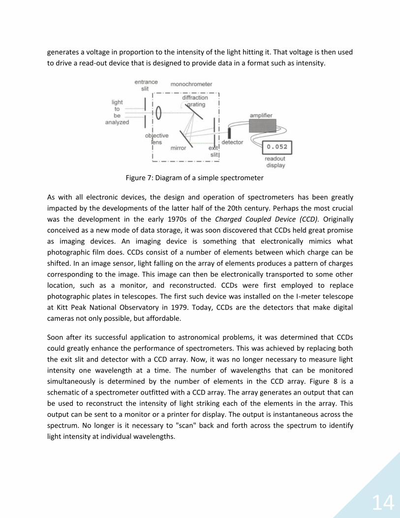
The diagram of a simple spectrometer is shown in Figure 7. Light enters the spectrometer viathe entrance slit and then passes through several parts: an objective lens, a grating, and an exitslit. This combination of parts functions as a monochromator, a device that selects only onecolor (actually, a narrow band of wavelengths) from all of the wavelengths/colors present in thesource. A particular wavelength is selected, using the wavelength control, by adjusting theangle of the grating. This works because different wavelengths of light reflect off the grating atdifferent angles. The net result is the separation of white light into a "rainbow," much like theeffect of light transmitted through a prism of glass. The selected wavelength is at the center ofthe narrow band of wavelengths passing through the slit. The light then strikes a detector that
14
generates a voltage in proportion to the intensity of the light hitting it. That voltage is then usedto drive a read-out device that is designed to provide data in a format such as intensity.
As with all electronic devices, the design and operation of spectrometers has been greatlyimpacted by the developments of the latter half of the 20th century. Perhaps the most crucialwas the development in the early 1970s of the Charged Coupled Device (CCD). Originallyconceived as a new mode of data storage, it was soon discovered that CCDs held great promiseas imaging devices. An imaging device is something that electronically mimics whatphotographic film does. CCDs consist of a number of elements between which charge can beshifted. In an image sensor, light falling on the array of elements produces a pattern of chargescorresponding to the image. This image can then be electronically transported to some otherlocation, such as a monitor, and reconstructed. CCDs were first employed to replacephotographic plates in telescopes. The first such device was installed on the I-meter telescopeat Kitt Peak National Observatory in 1979. Today, CCDs are the detectors that make digitalcameras not only possible, but affordable.
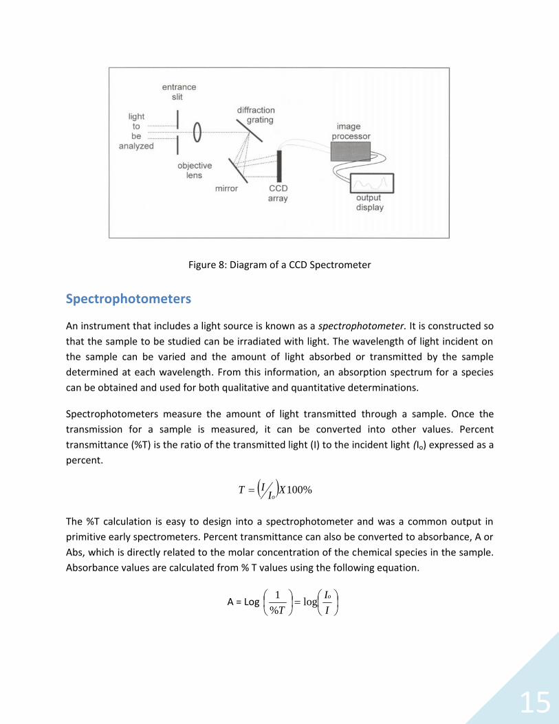
Soon after its successful application to astronomical problems, it was determined that CCDscould greatly enhance the performance of spectrometers. This was achieved by replacing boththe exit slit and detector with a CCD array. Now, it was no longer necessary to measure lightintensity one wavelength at a time. The number of wavelengths that can be monitoredsimultaneously is determined by the number of elements in the CCD array. Figure 8 is aschematic of a spectrometer outfitted with a CCD array. The array generates an output that canbe used to reconstruct the intensity of light striking each of the elements in the array. Thisoutput can be sent to a monitor or a printer for display. The output is instantaneous across thespectrum. No longer is it necessary to "scan" back and forth across the spectrum to identifylight intensity at individual wavelengths.
Figure 7: Diagram of a simple spectrometer
15
Spectrophotometers
An instrument that includes a light source is known as a spectrophotometer. It is constructed sothat the sample to be studied can be irradiated with light. The wavelength of light incident onthe sample can be varied and the amount of light absorbed or transmitted by the sampledetermined at each wavelength. From this information, an absorption spectrum for a speciescan be obtained and used for both qualitative and quantitative determinations.
Spectrophotometers measure the amount of light transmitted through a sample. Once thetransmission for a sample is measured, it can be converted into other values. Percenttransmittance (%T) is the ratio of the transmitted light (I) to the incident light (Io) expressed as apercent.
%100XIIT
o
The %T calculation is easy to design into a spectrophotometer and was a common output inprimitive early spectrometers. Percent transmittance can also be converted to absorbance, A orAbs, which is directly related to the molar concentration of the chemical species in the sample.Absorbance values are calculated from % T values using the following equation.
A = Log
I
I
T
olog
%
1
Figure 8: Diagram of a CCD Spectrometer

16
There is an assumption inherent in the calculation of either %T or absorbance. The assumptionis that all light not transmitted to the detector is absorbed by the chemical compounds in thesolution. Two other possibilities exist. One is that the light is being scattered by the solution.Light interacting with any particle that is larger than its wavelength can scatter light. Because ofthis, samples containing solid material or that are cloudy or turbid in nature are difficult toanalyze using a spectrophotometer. Samples encountered in the commercial world (biologicalfluids, soil solutions, etc.) are often cloudy and extra steps must be employed before analysis byabsorption spectrophotometry can begin.
Another consideration is that light can be scattered or absorbed by the container used to holdthe solution. Care must be taken to ensure that the sample cells are clean and free fromfingerprints so they do not affect the measurement. The cells must also be constructed ofabsolutely transparent material free of defect. If measurements are to be made below 350 nm,the cells must be made of quartz or other materials that readily transmit UV light.
The Beer-Lambert Law
The relationship between absorbance and concentration is known as the Beer-Lambert Law, orsometimes simply Beer's Law,
A = ε l c
Where:
A = Measured absorbance,c = Concentration of the absorbing species,l = Pathlength of the sample (width of the cuvette)ε = Proportionality constant known as the molar absorptivity with units of (M-1cm-1).
The molar absorptivity (ε) is constant for a specific chemical compound at a specificwavelength. For most compounds, there is typically at least one wavelength where ε reaches amaximum. This wavelength is often chosen to carry out absorption spectrophotometry of thatcompound. For example, consider the absorbance spectra for hemoglobin shown in Figure 4.There are three wavelengths in the visible range that would be suitable for characterizing theabsorbance of hemoglobin: 412, 541 and 576 nm.
If the molar absorptivity is known at a particular wavelength, the concentration of a chemicalcompound present in a transparent sample can be calculated from the measured absorbanceusing Beer's Law. The simplest way to determine ε is to take a solution of known concentration,select the wavelength for which the value of ε is desired (usually the wavelength where the
17
absorbance has its greatest value), measure the absorbance there and measure the pathlength.The above equation can be rearranged to solve for ε (ε = A /lc) and the value computed fromthe experimental measurements.
It is important to remember that spectrometers are limited in their ability to measureabsorbance accurately; therefore, the results for very concentrated samples (with highabsorbance values) may not be reliable. For example, an inexpensive spectrometer mayproduce reliable results only in the absorbance range of 0.01 to 1.5. Absorbance values outsidethis range are not reliable due to instrument limitations. For the best results, multiplemeasurements of a number of samples under a variety of conditions are required to provide anaccurate answer.
A more accurate method to determine ε is to measure the absorbance of a number of solutionsof different concentrations and construct a calibration plot or standard curve. Beer's Law is alinear equation of the form
A = ε l c
y = mx + b
(b, the y intercept, is zero and therefore does not appear in the Beer's Law equation.)
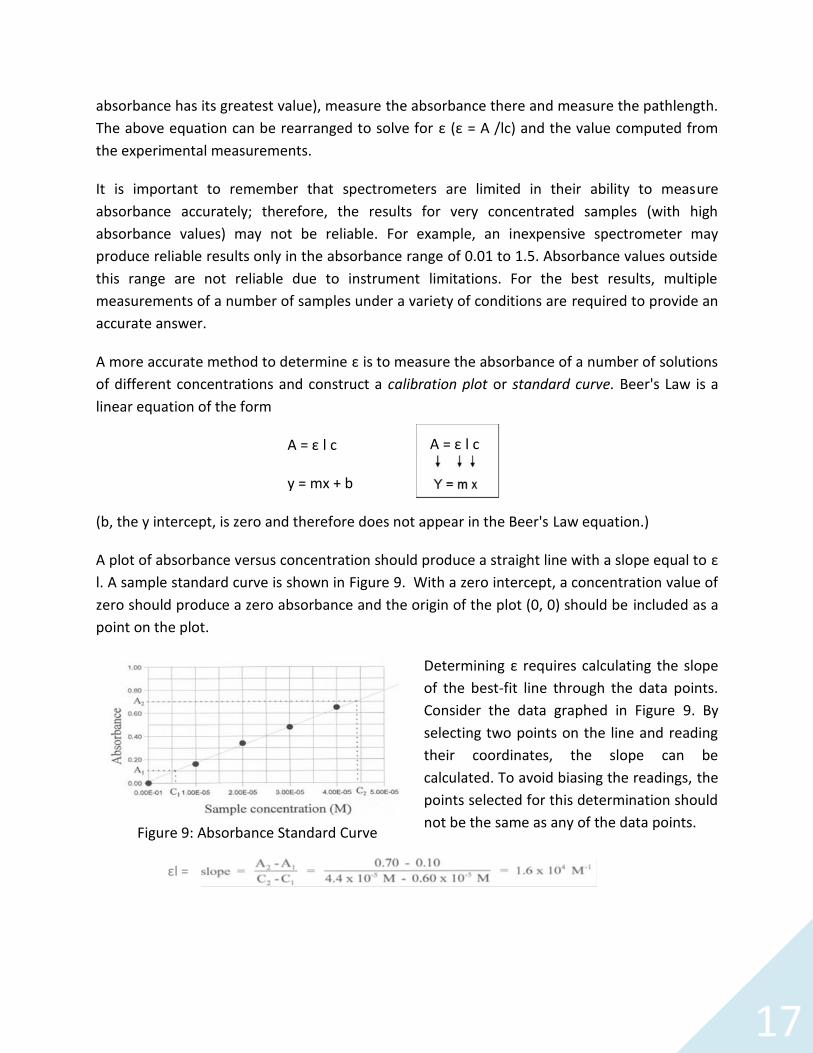
A plot of absorbance versus concentration should produce a straight line with a slope equal to εl. A sample standard curve is shown in Figure 9. With a zero intercept, a concentration value ofzero should produce a zero absorbance and the origin of the plot (0, 0) should be included as apoint on the plot.
Determining ε requires calculating the slopeof the best-fit line through the data points.Consider the data graphed in Figure 9. Byselecting two points on the line and readingtheir coordinates, the slope can becalculated. To avoid biasing the readings, thepoints selected for this determination shouldnot be the same as any of the data points.
εl =
Figure 9: Absorbance Standard Curve
A = ε l c
18
As long as the pathlength (l) through the sample can be measured, ε can be calculated from theslope. A quick measurement of pathlength can be made with a ruler. A more rigorous method isto measure the absorbance of a standard solution having a known concentration and molarabsorptivity and then calculate the pathlength from Beer's Law.
Note that the value of l may vary from cuvette to cuvette. It will also vary with the orientationof the cuvette in the sample holder if the cuvette does not have a uniform pathlength in alldirections. To maintain optimal accuracy, one should always use the same cuvette or at thevery least make sure cuvettes are oriented the same way every time they are placed in thespectrophotometer.
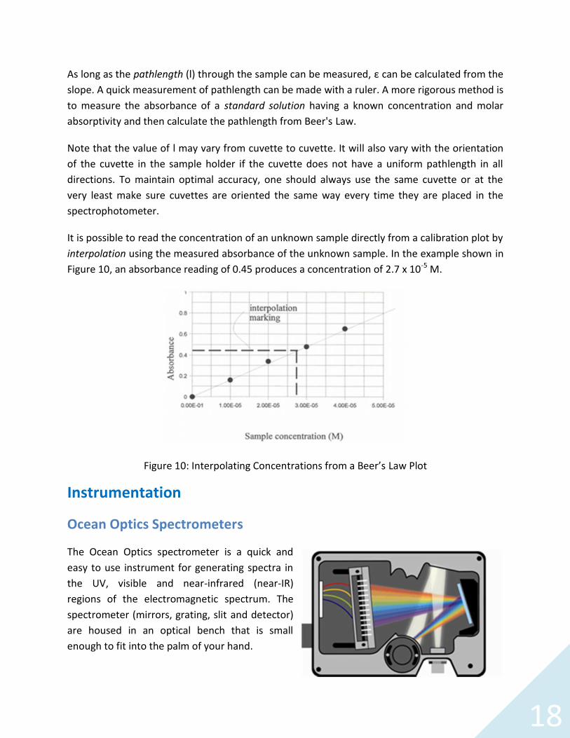
It is possible to read the concentration of an unknown sample directly from a calibration plot byinterpolation using the measured absorbance of the unknown sample. In the example shown inFigure 10, an absorbance reading of 0.45 produces a concentration of 2.7 x 10⁻⁵ M.
Figure 10: Interpolating Concentrations from a Beer’s Law Plot
Instrumentation
Ocean Optics Spectrometers
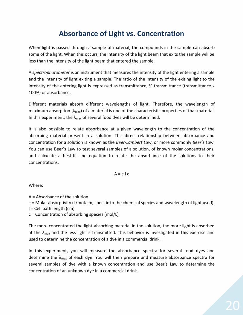
The Ocean Optics spectrometer is a quick andeasy to use instrument for generating spectra inthe UV, visible and near-infrared (near-IR)regions of the electromagnetic spectrum. Thespectrometer (mirrors, grating, slit and detector)are housed in an optical bench that is smallenough to fit into the palm of your hand.

19
The spectrometer accepts light energy – either transmitted through an optical fiber or in freespace -- and disperses it via a fixed grating across the linear CCD detector. The detector isdesigned to provide an electronic output for its wavelength range. The output from thedetector is then fed into the computer to software, processed, and then displayed in theappropriate units. The spectrum you see is the result of multiple detector elements being fedinto the computer and processed. This happens fast enough for you to be looking at the spectragenerated by the instrument in real time.
Ocean Optics Spectrophotometers
Ocean Optics spectrometers can also be used to makeabsorbance measurements when used in conjunctionwith a light source and cell holder as shown in Figure 11.To measure absorbance, the instrument must becalibrated. This is done by first measuring the number ofcounts at each of the detector elements from the lightsource as it passes through a reference solution (solventwithout the analyte of interest). Next, the background ornumber of counts when the light source is blocked (nolight is entering the spectrometer) is measured. Both ofthese operations are automatically performed by thesoftware when the appropriate buttons are pushed. Once the instrument has been calibratedand a sample is inserted into the holder, the computer calculates the ratio of the counts hittingthe detector to the stored reference counts for each of the detector elements and convertsthese to absorbance values displayed as an absorbance spectrum.
Figure 11: Ocean Optics FlameSpectrometer with Vis-NIR
Integrated Sampling System
20
Absorbance of Light vs. Concentration
When light is passed through a sample of material, the compounds in the sample can absorbsome of the light. When this occurs, the intensity of the light beam that exits the sample will beless than the intensity of the light beam that entered the sample.
A spectrophotometer is an instrument that measures the intensity of the light entering a sampleand the intensity of light exiting a sample. The ratio of the intensity of the exiting light to theintensity of the entering light is expressed as transmittance, % transmittance (transmittance x100%) or absorbance.
Different materials absorb different wavelengths of light. Therefore, the wavelength ofmaximum absorption (λmax) of a material is one of the characteristic properties of that material.In this experiment, the λmax of several food dyes will be determined.
It is also possible to relate absorbance at a given wavelength to the concentration of theabsorbing material present in a solution. This direct relationship between absorbance andconcentration for a solution is known as the Beer-Lambert Law, or more commonly Beer’s Law.You can use Beer’s Law to test several samples of a solution, of known molar concentrations,and calculate a best-fit line equation to relate the absorbance of the solutions to theirconcentrations.
A = ε l c
Where:
A = Absorbance of the solutionε = Molar absorptivity (L/mol•cm, specific to the chemical species and wavelength of light used)l = Cell path length (cm)c = Concentration of absorbing species (mol/L)
The more concentrated the light-absorbing material in the solution, the more light is absorbedat the λmax and the less light is transmitted. This behavior is investigated in this exercise andused to determine the concentration of a dye in a commercial drink.
In this experiment, you will measure the absorbance spectra for several food dyes anddetermine the λmax of each dye. You will then prepare and measure absorbance spectra forseveral samples of dye with a known concentration and use Beer’s Law to determine theconcentration of an unknown dye in a commercial drink.
21
Materials
Ocean Optics Flame Spectrometer and direct attach light source-cuvette holder (orstandalone light source, cuvette holder and optical fibers)
Computer with OceanView software installed Commercial food dyes Distilled water for diluting food dyes Commercial drinks containing food dyes 10 mL volumetric flasks Transfer/Beral pipettes Cuvettes
Safety
Wear safety goggles and other appropriate safety gear (gloves or apron) during the experiment.Take all proper safety precautions when handling the solutions.
The Absorbance of Commercial Food Dyes
Several samples of commercial food dyes are available for this lab. Work in groups of two tothree to determine the λmax of the food dyes. The Ocean Optics spectrometer will be used totest the absorbance of the dye over a selected wavelength range.
1. Connect the spectrometer to your computer using the USB cable and turn on your lightsource. If you are using a direct attach light source, start the OceanView software and clickthe Strobe/Lamp Enable box in the Acquisition Group Window to turn the lamp on.
2. Allow the spectrometer and light source to warm up for at least 15 minutes beforeproceeding.
3. If you have not already done so, start OceanView. Click the Start button, then select All
Programs | Ocean Optics | OceanView | OceanView or use the Desktop shortcut createdwhen you installed the software.
4. Select the Spectroscopy Application Wizards option on the Welcome Screen.
22
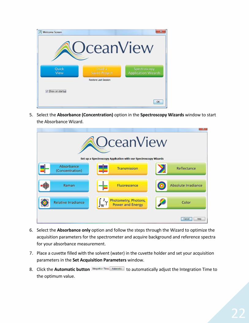
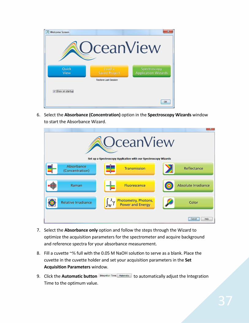
5. Select the Absorbance (Concentration) option in the Spectroscopy Wizards window to startthe Absorbance Wizard.
6. Select the Absorbance only option and follow the steps through the Wizard to optimize theacquisition parameters for the spectrometer and acquire background and reference spectrafor your absorbance measurement.
7. Place a cuvette filled with the solvent (water) in the cuvette holder and set your acquisitionparameters in the Set Acquisition Parameters window.
8. Click the Automatic button to automatically adjust the Integration Time tothe optimum value.

23
9. Set Scans to Average to 10 and Boxcar Width to 5 to reduce measurement noise and improvethe measurement. You can set the Scans to Average to a higher value but this will slow downyour acquisitions (total measurement time equals number of averages multiplied by theintegration time).
10. Place a checkmark in the Nonlinearity Correction box if this feature is available for yourspectrometer.
11. Click Next.
12. Click the Store Reference (yellow light bulb) button to store a reference spectrum. Click Next.
13. For direct attach light sources, click the Strobe/Lamp Enable box to close the shutter of thelight source for your Background measurement. For other light sources, block the light fromentering the spectrometer (do not turn your light source off). Click the Store Background(gray light bulb) button to store a background spectrum.
14. If you are using a direct attach light source, click the Strobe/Lamp Enable box to open theshutter. Click Finish. You are now ready to measure absorbance spectra.
15. The Absorbance spectra will be displayed in the AbsorbanceView window. You can adjust the
graph appearance using the graph tools above the absorbance graph.
For this experiment, click the Manually Set Numeric Ranges button to reset thewavelength scale to your region of interest from 400 to 700 nm. Click Apply to accept yourchanges and Exit to close the dialog box. Click the Scale Graph Height to Fill Window button
to zoom in on the absorbance spectra.
16. Rinse the cuvette with the solution to be tested and fill it with the solution. Insert the cuvetteinto the cuvette holder and acquire the absorbance spectrum.
17. Save your absorbance spectrumby clicking the Configure Graph
Saving button to configurethe File Writer.
a. Select the directory whereyou want to save the file.
b. Enter a filename for yourspectrum.
c. Click Apply and then Exit toclose the dialog box.

24
18. Click the Save Graph to Files button to save your absorbance spectrum.
19. Click the Convert Active Spectrum to Overlay button to create an overlay of thespectrum.
20. To find the wavelength of maximum absorbance, click anywhere on the graph to activate thecursor. A panel below the graph identifies the wavelength and intensity at the cursor position.Move the cursor on the graph until you find the wavelength where the highest absorbanceoccurs for each of the dyes. Record the λmax of the dye.
21. Repeat Steps 12 through 16 until all the dyes have been tested.
22. If a printer is available, print your data by clicking the Print graph button . Attach theprintout of your absorbance spectra or draw the graph in your notebook.
Determine the Relationship of Absorbance to Concentration at λmax
1. Obtain a 20 mL sample of one of the food dyes. Each student needs to investigate one dye.
2. Label the undiluted sample Solution A and record its concentration.
3. Make a series of dilutions of the sample using the dye and distilled water. Record the volumeused for each dilution. When diluting a sample of solution A to make a new solution, theamount of solute does not change. Therefore, the concentrations of the new solutions can bedetermined by the following relationship:
MAVA =MBVB
where M is the molarity of the solution (or concentration in this case), V is the volume of
solution, A is the initial solution and B is the final solution.
Solution B: Pipette 5.00 mL of Solution A into a 10.00 mL volumetric flask. Dilute to themark with water. Mix thoroughly and label as Solution B and its concentration.
Solution C: Pipette 2.00 mL of Solution A into another 10.00 mL volumetric flask. Dilute,mix as before and label.
Solution D: Pipette 1.00mL of Solution A into a third 10.00 mL volumetric flask. Dilute, mixas before and label.
4. Place the cursor in your graph window on the λmax for your dye.
5. Record the absorbance for solutions D, C, B, and A at λmax. It is advisable to begin with theleast concentrated solution to avoid sample carry over in the cuvette.

25
6. Obtain a sample of one of the commercial drinks that contains the dye you are investigating.Take the absorbance spectrum of the sample and record the absorbance at λmax.
Data Analysis
1. Use a Microsoft Excel spreadsheet to graph the absorbance versus concentration.
2. By linear regression using Excel or a graphing calculator, determine the equation for the "bestfit" line through your data points and record the value of R2. An R2 value close to 1.00indicates that the line fits the data points well.
3. Determine the equation for the best fit line of the graph of absorbance versus concentration:
y = mx + bWhere:y = Absorbancex = Concentrationm = Slope of the lineb = y intercept
4. Report the concentration of the dye in the commercial drink using your Beer's Law standardcurve (the best fit line equation) to relate the commercial dye absorbance to concentration.
Discussion Questions
1. Discuss the relationship between absorbance and concentration using the data from thisexperiment. This relationship is called Beer's Law.
2. Student Problem: A soft drink company found that stores in their market area were notbuying as many cases of their product as usual. Investigation showed that the stores hadpurchased the same number of cases but not from the company representative. Thecompany was sure someone was counterfeiting their labels and selling imitations of theirproducts.
The chemical analysis lab for which you work has been asked to submit a bid for the job ofanalyzing the suspected merchandise. Your job as a chemist is to work with samples of acommercial soft drink containing two food dyes and to develop a method to:
Determine the food dyes in a drink Determine the concentration of each food dye in the drink Separate the food dyes in the drink samples so that further analysis by an organic
laboratory can be done on each dye separately (NOTE: A nonpolar column must beused for this problem.)
26
The Absorbance Spectrum of Chlorophyll
The mixture of two chlorophyll molecules (chlorophyll a and b) from green, leafy plantsabsorbs several wavelengths of visible light, with five distinct absorbance peaks: three inthe blue range (413, 454, and 482 nm) and two yellows (631 and 669 nm). Thecombination of these wavelengths is green to the human eye, but different ratios ofthese chlorophylls can create many shades of green.
In this experiment you will extract chlorophyll from spinach (or some other fresh greenleafy sample) and measure its absorbance spectrum. While you wait for the extract todevelop, you will measure the absorbance of blue and yellow food color samples so youwill know what to expect when you measure the absorbance of your chlorophyll extract.
Materials
Ocean Optics Flame Spectrometer and direct attach light source-cuvette holder (orstandalone light source, cuvette holder and optical fibers)
Computer with OceanView software installed Spinach or fresh green leaves Isopropanol or ethanol Yellow and blue food color solutions Three small beakers Mortar and pestle Two 10 mL graduated cylinders Funnel and filter paper Ring stand and ring Plastic Transfer/Beral pipettes Cuvettes
Safety
Wear safety goggles and other appropriate safety gear (gloves or apron) during theexperiment. Take all proper safety precautions when handling the solutions.

27
The Absorbance of Food Coloring
1. Obtain small amounts of blue and yellow food coloring solutions.
2. Connect the spectrometer to your computer using the USB cable and turn on yourlight source. If you are using a direct attach light source, start the OceanView softwareand click the Strobe/Lamp Enable box in the Acquisition Group Window to turn thelamp on.
3. Allow the spectrometer and light source to warm up for at least 15 minutes beforeproceeding.
4. If you have not already done so, start the OceanView software. Click the Start button,
then select All Programs | Ocean Optics | OceanView | OceanView.
5. Select the Spectroscopy Application Wizards option on the Welcome Screen.
6. Select the Absorbance (Concentration) option in the Spectroscopy Wizards windowto start the Absorbance Wizard.

28
7. Select the Absorbance only option and follow the steps through the Wizard tooptimize the acquisition parameters for the spectrometer and acquire backgroundand reference spectra for your absorbance measurement.
8. Fill a cuvette ~⅔ full with dis lled water to serve as a blank/reference. Place thecuvette in the cuvette holder and set your acquisition parameters in the SetAcquisition Parameters window.
9. Click the Automatic button to automatically adjust the IntegrationTime to the optimum value.
10. Set Scans to Average to 10 and Boxcar Width to 5 to reduce measurement noise andimprove the measurement. You can set the Scans to Average to a higher value butthis will slow down your acquisitions (total measurement time equals number ofaverages multiplied by the integration time).
11. Place a checkmark in the Nonlinearity Correction box if this feature is available foryour spectrometer.
12. Click Next.
13. Click the Store Reference (yellow light bulb) to store a reference spectrum. Click Next.
14. For direct attach light sources, click the Strobe/Lamp Enable box to close the shutterof the light source for your Background measurement. For other light sources, blockthe light from entering the spectrometer (do not turn your light source off). Click theStore Background (gray light bulb) button to store a background spectrum.
29
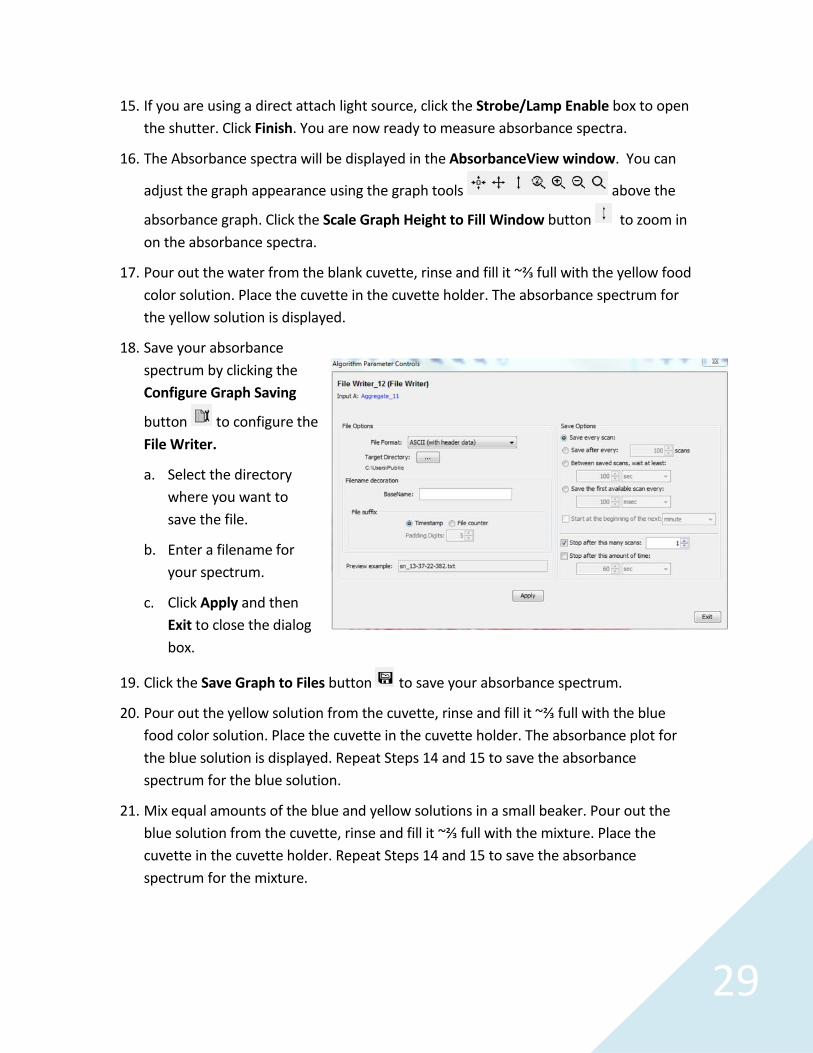
15. If you are using a direct attach light source, click the Strobe/Lamp Enable box to openthe shutter. Click Finish. You are now ready to measure absorbance spectra.
16. The Absorbance spectra will be displayed in the AbsorbanceView window. You can
adjust the graph appearance using the graph tools above the
absorbance graph. Click the Scale Graph Height to Fill Window button to zoom inon the absorbance spectra.
17. Pour out the water from the blank cuvette, rinse and fill it ~⅔ full with the yellow foodcolor solution. Place the cuvette in the cuvette holder. The absorbance spectrum forthe yellow solution is displayed.
18. Save your absorbancespectrum by clicking theConfigure Graph Saving
button to configure theFile Writer.
a. Select the directorywhere you want tosave the file.
b. Enter a filename foryour spectrum.
c. Click Apply and thenExit to close the dialogbox.
19. Click the Save Graph to Files button to save your absorbance spectrum.
20. Pour out the yellow solution from the cuvette, rinse and fill it ~⅔ full with the bluefood color solution. Place the cuvette in the cuvette holder. The absorbance plot forthe blue solution is displayed. Repeat Steps 14 and 15 to save the absorbancespectrum for the blue solution.
21. Mix equal amounts of the blue and yellow solutions in a small beaker. Pour out theblue solution from the cuvette, rinse and fill it ~⅔ full with the mixture. Place thecuvette in the cuvette holder. Repeat Steps 14 and 15 to save the absorbancespectrum for the mixture.
30
The Absorbance of Chlorophyll
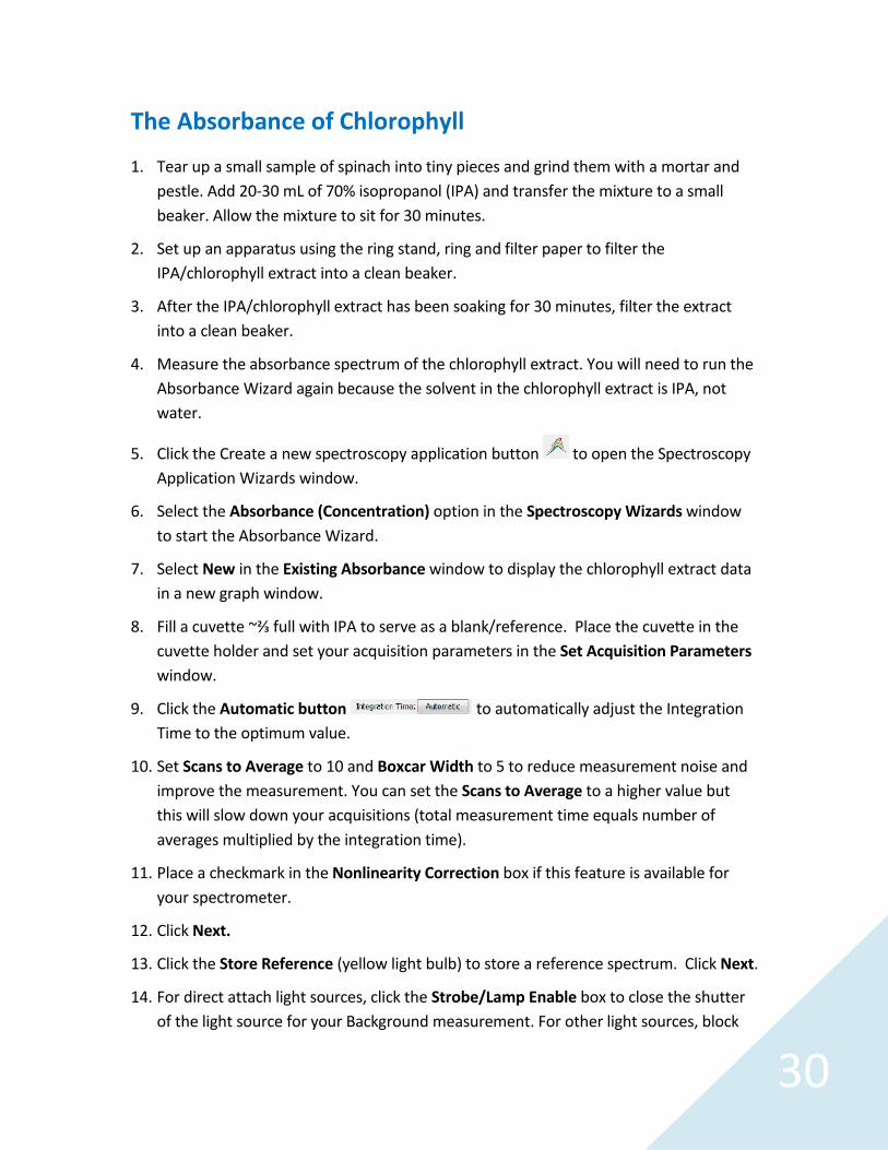
1. Tear up a small sample of spinach into tiny pieces and grind them with a mortar andpestle. Add 20-30 mL of 70% isopropanol (IPA) and transfer the mixture to a smallbeaker. Allow the mixture to sit for 30 minutes.
2. Set up an apparatus using the ring stand, ring and filter paper to filter theIPA/chlorophyll extract into a clean beaker.
3. After the IPA/chlorophyll extract has been soaking for 30 minutes, filter the extractinto a clean beaker.
4. Measure the absorbance spectrum of the chlorophyll extract. You will need to run theAbsorbance Wizard again because the solvent in the chlorophyll extract is IPA, notwater.
5. Click the Create a new spectroscopy application button to open the SpectroscopyApplication Wizards window.
6. Select the Absorbance (Concentration) option in the Spectroscopy Wizards windowto start the Absorbance Wizard.
7. Select New in the Existing Absorbance window to display the chlorophyll extract datain a new graph window.
8. Fill a cuvette ~⅔ full with IPA to serve as a blank/reference. Place the cuve e in thecuvette holder and set your acquisition parameters in the Set Acquisition Parameterswindow.
9. Click the Automatic button to automatically adjust the IntegrationTime to the optimum value.
10. Set Scans to Average to 10 and Boxcar Width to 5 to reduce measurement noise andimprove the measurement. You can set the Scans to Average to a higher value butthis will slow down your acquisitions (total measurement time equals number ofaverages multiplied by the integration time).
11. Place a checkmark in the Nonlinearity Correction box if this feature is available foryour spectrometer.
12. Click Next.
13. Click the Store Reference (yellow light bulb) to store a reference spectrum. Click Next.
14. For direct attach light sources, click the Strobe/Lamp Enable box to close the shutterof the light source for your Background measurement. For other light sources, block

31
the light from entering the spectrometer (do not turn your light source off). Click theStore Background (gray light bulb) button to store a background spectrum.
15. If you are using a direct attach light source, click the Strobe/Lamp Enable box to openthe shutter. Click Finish. You are now ready to measure absorbance spectra.
16. The Absorbance spectra will be displayed in the AbsorbanceView window. You can
adjust the graph appearance using the graph tools above the
absorbance graph. Click the Scale Graph Height to Fill Window button to zoom inon the absorbance spectra.
17. Measure the absorbance of the chlorophyll extract. Pour out the IPA from the blankcuvette, rinse and fill it ~⅔ full with the chlorophyll extract. Place the cuve e in thecuvette holder. The chlorophyll absorbance spectrum is displayed.
18. Save the chlorophyll absorbance spectrum by clicking the Configure Graph Saving
button to configure theFile Writer.
19. Select the directory whereyou want to save the file.
20. Enter a filename for yourspectrum.
21. Click Apply and then Exit toclose the dialog box.
22. Click the Save Graph to Files
button to save yourabsorbance spectrum.
32
Discussion Questions
1. Consult a reliable resource to identify the major absorbance peaks of chlorophyll aand chlorophyll b. Examine the absorbance spectra for chlorophyll. Does your graphclearly show these absorbance peaks? Are there other, unidentified peaks on yourgraph? Identify them and speculate about what caused these peaks.
2. How did your tests of the absorbance of the blue and yellow food coloring solutionscompare with the tests of the chlorophyll extract?
3. If distilled water had been used as the calibration blank for the chlorophyll test,would it have affected the absorbance measurements?
4. Were the distinguishing features of chlorophyll a and b evident in the absorbancespectrum graph of the chlorophyll extract? Explain.

33
Determining the Rate law of a Chemical Reaction:Kinetics of Crystal Violet Bleaching
Chemists are always interested in whether a chemical reaction can occur and exactlyhow it occurs. The first question is answered through thermodynamics while the secondis the domain of kinetics. In a kinetics experiment, a chemist attempts to understand thestep-by-step transformation of reactants to products. Taken together these elementarysteps give us the mechanism by which the reaction proceeds. Note that a reaction'skinetics are very much tied to the pathway the reactants take to the products (i.e., themechanism), which is very different from the reaction's thermodynamic properties (i.e.,∆H (Enthalpy), ∆S (Entropy) and ∆G (Gibbs Free Energy) that do not depend on the path.While the thermodynamics and kinetics of a reaction may at times seemcomplementary, and at other times seem contradictory, it is always important to have adetailed understanding of both.
In this experiment, you will determine the rate law for a chemical reaction. The rate lawis a mathematical expression relating to chemical reactions. The amount of time it takesa reaction to occur correlates to the concentrations of the starting materials. Thedisappearance of reactant over time depends on the rate constant and theconcentration of each reactant raised to some power. This power is known as the orderof reaction with respect to that reactant. The sum of the individual orders is the overallorder of the reaction. The order of reaction with respect to each reactant, as well as therate law itself, cannot be determined from the balanced chemical equation; it must befound experimentally. The rate law is the basic equation of kinetics and it will be thestandard against which possible mechanisms are judged.
Reaction of Crystal Violet with OH-
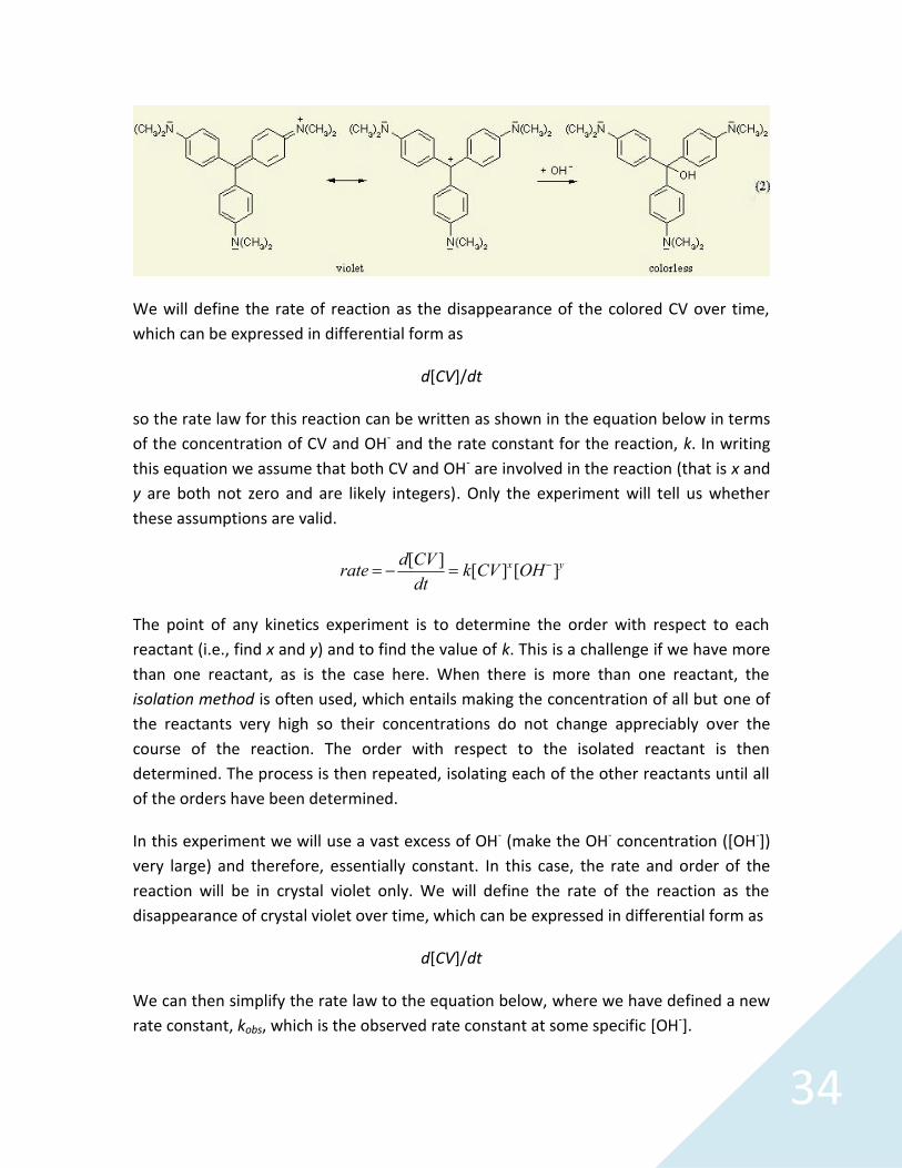
In this experiment, you will determine the rate law and order for the reaction of a dye,crystal violet (CV) with sodium hydroxide (OH-) in aqueous solution according to thebalanced net ionic equation shown below.
34
We will define the rate of reaction as the disappearance of the colored CV over time,which can be expressed in differential form as
d[CV]/dt
so the rate law for this reaction can be written as shown in the equation below in termsof the concentration of CV and OH- and the rate constant for the reaction, k. In writingthis equation we assume that both CV and OH- are involved in the reaction (that is x andy are both not zero and are likely integers). Only the experiment will tell us whetherthese assumptions are valid.
rate d[CV ]dt k[CV ]x[OH]y
The point of any kinetics experiment is to determine the order with respect to eachreactant (i.e., find x and y) and to find the value of k. This is a challenge if we have morethan one reactant, as is the case here. When there is more than one reactant, theisolation method is often used, which entails making the concentration of all but one ofthe reactants very high so their concentrations do not change appreciably over thecourse of the reaction. The order with respect to the isolated reactant is thendetermined. The process is then repeated, isolating each of the other reactants until allof the orders have been determined.
In this experiment we will use a vast excess of OH- (make the OH- concentration ([OH-])very large) and therefore, essentially constant. In this case, the rate and order of thereaction will be in crystal violet only. We will define the rate of the reaction as thedisappearance of crystal violet over time, which can be expressed in differential form as
d[CV]/dt
We can then simplify the rate law to the equation below, where we have defined a newrate constant, kobs, which is the observed rate constant at some specific [OH-].
35
rate kobs[CV ]x
The relationship between kobs and the intrinsic rate constant, k, for this reaction is givenby the equation below.
kobs k[OH]y
Under conditions of high, constant [OH-], the order with respect to CV can bedetermined by graphically applying the integrated rate laws. Since the absorbance of aCV solution is directly proportional to the concentration of CV ([CV]), according to Beers'Law, the actual [CV] can be replaced by Amax, the solution's maximum absorbance(somewhere around 600 nm). A graph of Amax as a function of time will give a straightline if the reaction is zero-order in CV (x = 0). If the reaction is first-order in CV (x = 1),then a graph of ln(Amax) as a function of time is linear. Finally, if a graph of 1/Amax as afunction of time is linear, it indicates that the reaction is second-order with respect toCV (x = 2). In each case, if a particular relationship is linear, then the slope of that graphcan be used to determine kobs. Note that only one of these three graphs will be linear!
In some instances it is not possible to isolate one of the reactants, because theconcentration of that reactant must remain high for the system to behave predictably.In this reaction the [OH-] must remain high, but the order of the reaction with respect toOH-and k, can still be found. First we need to change the rate law into an easily graphedform by taking the natural logarithm of both sides to give
ln(kobs) y ln[OH] ln(k)
To determine the order with respect to OH- and k, we first perform the kineticsexperiment at different, albeit still high, OH- concentrations and then graph ln(kobs) forthese reactions as a function of ln[OH-]. The slope of this graph is y, the order withrespect to OH-, and the intercept is ln(k).
In this experiment, you will measure the absorbance of the reaction over time, at aspecific wavelength of visible light. You will first measure the absorbance spectrum of acrystal violet solution and select one wavelength to examine during the reaction. As thereaction proceeds, the bright purple color of the crystal violet solution will fade and theabsorbance will decrease.

36
Materials
Ocean Optics Flame Spectrometer and direct attach light source-cuvette holder (orstandalone light source, cuvette holder and optical fibers)
Computer with OceanView software installed 1.0 × 10⁻⁴ M crystal violet solution 0.05 M NaOH solution Two 10 mL graduated cylinders or pipettes Three small beakers Plastic Transfer/Beral pipettes Cuvettes
Safety
Wear safety goggles and other appropriate safety gear (gloves or apron) during theexperiment. Take all proper safety precautions when handling the solutions.
Measuring the Kinetics of Crystal Violet Bleaching
1. Obtain 15-20 mL of the crystal violet (CV) and sodium hydroxide (OH-) solutions.
2. Connect the spectrometer to your computer using the USB cable and turn on yourlight source. If you are using a direct attach light source, start the OceanView softwareand click the Strobe/Lamp Enable box in the Acquisition Group Window to turn thelamp on.
3. Allow the spectrometer and light source to warm up for at least 15 minutes beforeproceeding.
4. If you have not already done so, start OceanView. Click the Start button, then select
All Programs | Ocean Optics | OceanView | OceanView or use the Desktopshortcut created when you installed the software.
5. Select the Spectroscopy Application Wizards option on the Welcome Screen.
37
6. Select the Absorbance (Concentration) option in the Spectroscopy Wizards windowto start the Absorbance Wizard.
7. Select the Absorbance only option and follow the steps through the Wizard tooptimize the acquisition parameters for the spectrometer and acquire backgroundand reference spectra for your absorbance measurement.
8. Fill a cuvette ~⅔ full with the 0.05 M NaOH solu on to serve as a blank. Place thecuvette in the cuvette holder and set your acquisition parameters in the SetAcquisition Parameters window.
9. Click the Automatic button to automatically adjust the IntegrationTime to the optimum value.

38
10. Set Scans to Average to 10 and Boxcar Width to 5 to reduce measurement noise andimprove the measurement. You can set the Scans to Average to a higher value butthis will slow down your acquisitions (total measurement time equals number ofaverages times the integration time).
11. Place a checkmark in the Nonlinearity Correction box if this feature is available foryour spectrometer.
12. Click Next.
13. Click the Store Reference (yellow light bulb) to store a reference spectrum. Click Next.
14. For direct attach light sources, click the Strobe/Lamp Enable box to close the shutterof the light source for your Background measurement. For other light sources, blockthe light from entering the spectrometer (do not turn your light source off). Click theStore Background (gray light bulb) button to store a background spectrum.
15. If you are using a direct attach light source, click the Strobe/Lamp Enable box to openthe shutter. Click Finish. You are now ready to measure absorbance spectra.
16. The Absorbance spectra will be displayed in the AbsorbanceView window. You can
adjust the graph appearance using the graph tools above the
absorbance graph. Click the Scale Graph Height to Fill Window button to zoom inon the absorbance spectra.
17. Click the Create Strip Chart button .
a. Select the data source for the stripchart. Make sure to highlight thedata source with Spectrum TypeAbsorbance.
b. In the Update Rate panel, checkthe box next to Stop after thisamount of time and change thetime to 10 minutes.
c. In the Wavelength Selection panel,select One Wavelength and set itto 585 nm.
d. DO NOT click the Finish button until you have prepared your reaction asdescribed in the steps below.
39
18. To prepare for the reaction, pour out the NaOH solution from the blank cuvette andrinse the cuvette with distilled water.
19. Mix 10 mL of the OH-and CV solutions in a third beaker. Swirl the beaker gently, andthen use a plastic Beral pipette to transfer 2-3 mL of the reaction mixture to thecuvette.
20. Place the cuvette in the cuvette holder. Click the button. A graph ofabsorbance versus time will be displayed in the Trend window.
21. If the strip chart is not visible in the window, adjust the graph scale using the graph
tools above the absorbance graph.
22. If the strip chart is not scrolling (trend runs off the screen), click the Automatically
Scroll the Graph button to scroll the strip chart during the acquisition.
23. After the strip chart run ends, copy the data to the clipboard for additional analysis ina program like Microsoft Excel.
a. Click the Copy Data to Clipboard buttonb. Open Excel and paste the data into the worksheet.
Data Analysis
1. Prepare three plots: absorbance versus time, ln absorbance versus time and1/absorbance versus time. Calculate the best-fit line equation for the plot that is themost linear and write down the equation.
2. Based on the information provided in the introductory remarks, what is the order ofthe reaction with respect to crystal violet?
3. Based on the information provided in the introductory remarks, write the rate law forthis reaction.
40
Extension
In some instances it is not possible to isolate a reactant because the concentration ofthe reactant must remain high for the reaction to behave predictably. This is the casewith the reaction between crystal violet and sodium hydroxide; the [OH-] must remainhigh. However, the order of the reaction with respect to OH- and the subsequent ratelaw constant can still be determined.
To determine the order of the reaction in OH-, you must conduct the reaction usingdifferent concentrations (albeit in vast excess) of OH-. From each data collection run youwill calculate a value of k. Using the values of k and the [OH-], you will prepare a plot ofln [OH-] (the Y-values) versus ln k (the X-values). The best-fit line for this plot takes theform:
ln (kabs) = m ln [OH-] + ln k.
The slope, m, is the order of the reaction in OH- and the Y-intercept is the naturallogarithm of the rate constant.

41
Emission Spectra
A fascinating feature of spectroscopy is how one can make use of light to learn aboutatomic and molecular structure. Under certain conditions, an atom or molecule willabsorb or emit light. By examining and measuring the light that is absorbed or emittedby a substance, certain physical properties are revealed.
The electrons of atoms and molecules exist in specific energy states. The energy emittedby the excitation of electrons is limited to differences between these states, thusspecific energies of light are emitted. The color of a glowing LED, for example, is a resultof the energy of the emitted light. The energy and wavelength of the light is describedby the equation
E = hc/λ
where λ is the wavelength, h is Planck's constant (6.63 × 10⁻³⁴ J sec), and c is the speedof light (3.00 × 10⁸ m/sec).
If you are measuring the emission spectrum of a gas trapped in a discharge tube, onlycertain wavelengths of light are emitted by the gas and the “pattern” that is produced isunique for that substance.
In this experiment you will use the spectrometer outfitted with a fiber optic cable tomeasure the emission spectra of various sources of light.
Materials
Ocean Optics Flame Spectrometer Fiber optic cable Computer with OceanView software installed Light sources: LEDs, Lamps, Discharge Tubes
Safety
Wear safety goggles and other appropriate safety gear during the experiment. Take allproper safety precautions when working with light sources including eye protection.
42
Measuring Light Source Emission with a Spectrometer
1. Connect a fiber optic cable to the threaded SMA 905 connector on the housing ofthe spectrometer.
2. Connect the spectrometer to your computer using the USB cable.
3. Start the OceanView software. Click the Start button, then select All Programs |
Ocean Optics | OceanView | OceanView.
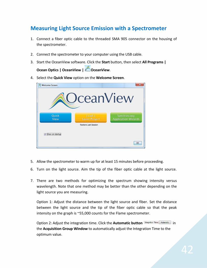
4. Select the Quick View option on the Welcome Screen.
5. Allow the spectrometer to warm up for at least 15 minutes before proceeding.
6. Turn on the light source. Aim the tip of the fiber optic cable at the light source.
7. There are two methods for optimizing the spectrum showing intensity versuswavelength. Note that one method may be better than the other depending on thelight source you are measuring.
Option 1: Adjust the distance between the light source and fiber. Set the distancebetween the light source and the tip of the fiber optic cable so that the peakintensity on the graph is ~55,000 counts for the Flame spectrometer.
Option 2: Adjust the integration time. Click the Automatic button inthe Acquisition Group Window to automatically adjust the Integration Time to theoptimum value.

43
8. When you are satisfied with your emission graph, save the spectrum by clicking the
Configure Graph Saving button to configure the File Writer.
a. Select the directorywhere you want to savethe file.
b. Enter a filename foryour spectrum.
c. Click Apply and thenExit to close the dialogbox.
9. Click the Save Graph to
Files button to saveyour emission spectrum.
10. To overlay your emission spectrum on the graph, click the Convert Active Spectrum
to Overlay button to create an overlay of the spectrum.
11. To analyze your emission spectrum graph:a. Click anywhere on the graph to activate the cursor. Note the vertical line
marking a given wavelength on the graph.b. Click on each peak of the emission spectrum. A legend below the graph
displays the counts at the wavelength of the cursor location. Write downthe wavelength for the peak or peaks in your spectrum, as well as anyother distinguishing characteristics of the graph, in your lab book.
12. Repeat Steps 6-11 to plot and capture the emission spectrum of a second lightsource.
13. Use the Convert Active Spectrum to Overlay option to show more than oneemission spectrum on the same graph. If you wish to remove a set of graphed data,
click the Delete Overlay Spectrum button . Highlight the spectrum you wantdeleted (all of the spectra are color coded) and click OK.
14. To export the graphed emission measurements to Microsoft Excel:
a. Click the Copy Data to Clipboard buttonb. Open Excel and paste the data into the worksheet.

44
Data Analysis
1. Examine your first graph of emission. Identify the peak or peaks. Describe thedistinguishing characteristics of the graph.
2. Examine your second graph of emission. As before, identify the peak or peaks anddescribe the distinguishing characteristics of the graph.
3. Are there any features of either graph that stand out as being unusual orunexpected?
4. Below are two emission graphs. The graph on the left is the emission from standardfluorescent office lighting. The graph on the right is the emission from a mercurydischarge tube. Using these graphs, make a case either for or against the presence ofmercury in the office lighting. The X- and Y-axis ranges for the graphs are identical.
45
Spectrophotometric Analysis of Commercial Aspirin
The concentration of acetylsalicylic acid (ASA) is determined spectrophotometrically bythe percent transmittance (%T) of visible light at a given wavelength
%T = (It/Io) x 100%
where It = Intensity of the beam transmitted by the solution, Io = Intensity of the lightbeam before it is passes through the sample solution.
The absorbance of the analyte in solution is related to the transmittance (T) as follows:
A = -log (It/Io)A = -log TA = -log (%T/100)A = -log (%T) + 2A = 2 - log (%T)
Beer’s Law says that
A = l c
where:
= Molar absorptivity of the particular absorbing species in (L /moles cm)l = Pathlength of the light through the solution in cmc = Concentration of the absorbing species in moles/L
From these equations, we can determine the concentration c, in mole/L, for theabsorbing species if the percent transmission (%T) can be determined from thespectrometer.
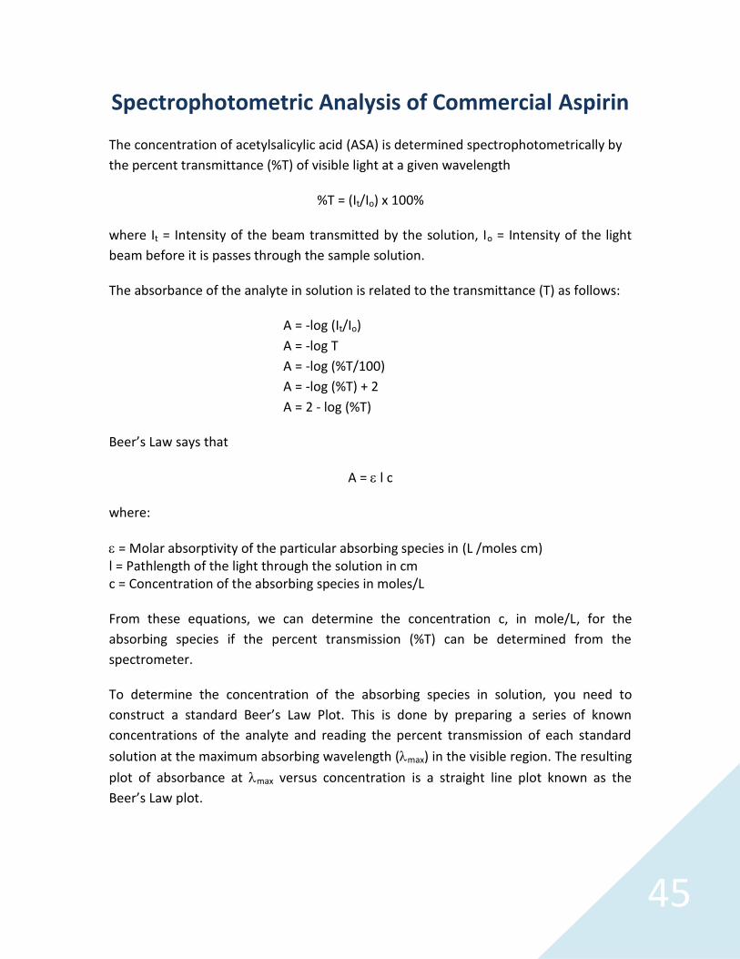
To determine the concentration of the absorbing species in solution, you need toconstruct a standard Beer’s Law Plot. This is done by preparing a series of knownconcentrations of the analyte and reading the percent transmission of each standardsolution at the maximum absorbing wavelength (max) in the visible region. The resultingplot of absorbance at max versus concentration is a straight line plot known as theBeer’s Law plot.
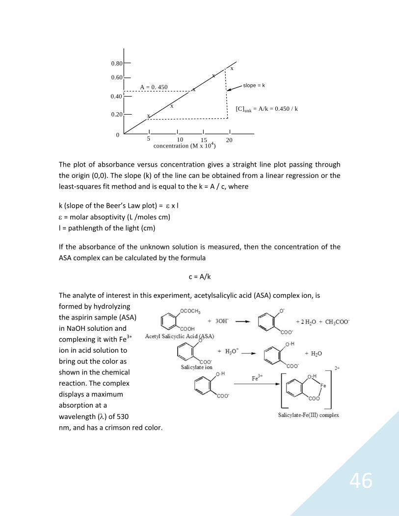
46
0
0.20
0.40
0.60
0.80
x
x
x
xx
5 10 15 20concentration (M x 104)
slope = kA = 0. 450
[C]unk = A/k = 0.450 / k
The plot of absorbance versus concentration gives a straight line plot passing throughthe origin (0,0). The slope (k) of the line can be obtained from a linear regression or theleast-squares fit method and is equal to the k = A / c, where
k (slope of the Beer’s Law plot) = x l = molar absoptivity (L /moles cm)l = pathlength of the light (cm)
If the absorbance of the unknown solution is measured, then the concentration of theASA complex can be calculated by the formula
c = A/k
The analyte of interest in this experiment, acetylsalicylic acid (ASA) complex ion, isformed by hydrolyzingthe aspirin sample (ASA)in NaOH solution andcomplexing it with Fe3+
ion in acid solution tobring out the color asshown in the chemicalreaction. The complexdisplays a maximumabsorption at awavelength () of 530nm, and has a crimson red color.
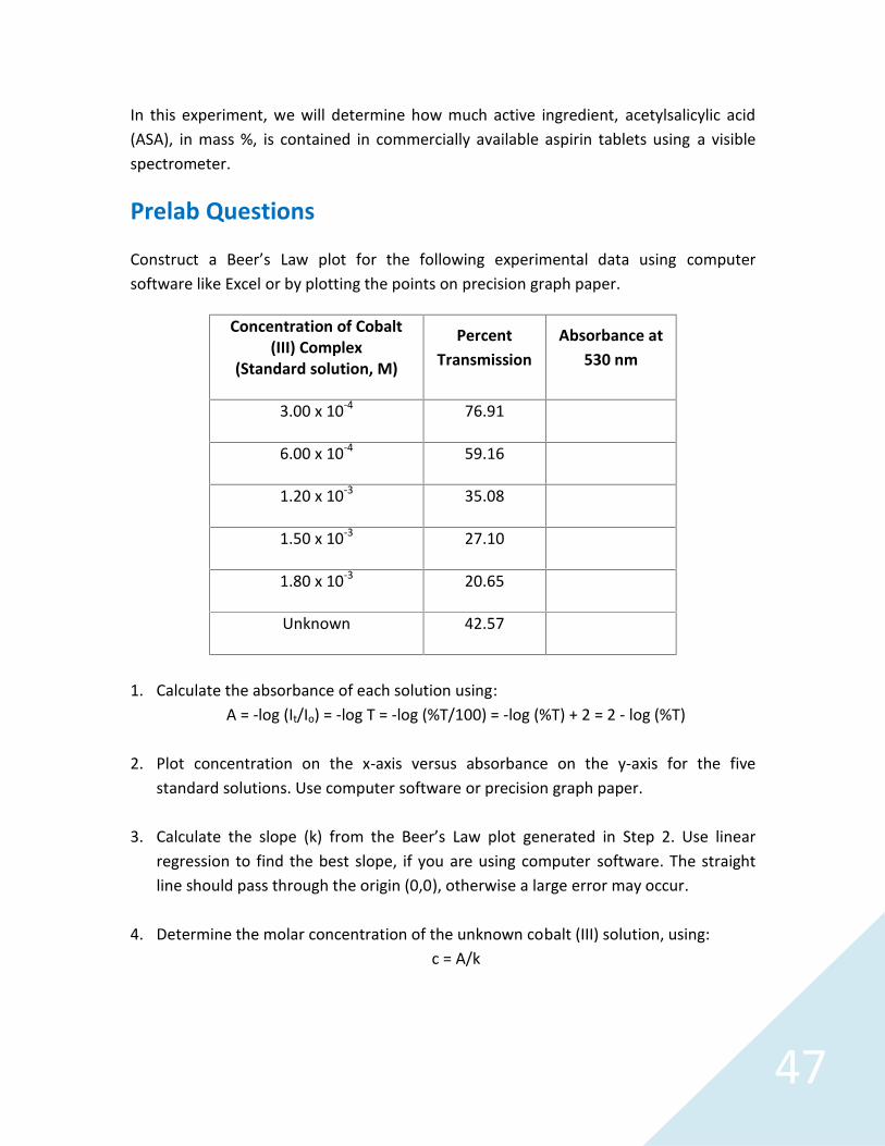
47
In this experiment, we will determine how much active ingredient, acetylsalicylic acid(ASA), in mass %, is contained in commercially available aspirin tablets using a visiblespectrometer.
Prelab Questions
Construct a Beer’s Law plot for the following experimental data using computersoftware like Excel or by plotting the points on precision graph paper.
Concentration of Cobalt(III) Complex
(Standard solution, M)
PercentTransmission
Absorbance at530 nm
3.00 x 10⁻⁴ 76.91
6.00 x 10⁻⁴ 59.16
1.20 x 10⁻³ 35.08
1.50 x 10⁻³ 27.10
1.80 x 10⁻³ 20.65
Unknown 42.57
1. Calculate the absorbance of each solution using:A = -log (It/Io) = -log T = -log (%T/100) = -log (%T) + 2 = 2 - log (%T)
2. Plot concentration on the x-axis versus absorbance on the y-axis for the fivestandard solutions. Use computer software or precision graph paper.
3. Calculate the slope (k) from the Beer’s Law plot generated in Step 2. Use linearregression to find the best slope, if you are using computer software. The straightline should pass through the origin (0,0), otherwise a large error may occur.
4. Determine the molar concentration of the unknown cobalt (III) solution, using:c = A/k
48
Materials
Ocean Optics Flame Spectrometer and direct attach light source-cuvette holder (orstandalone light source, cuvette holder and optical fibers)
Computer with OceanView software installed Reagent grade ASA (acetylsalicylic acid) Aspirin 1.0 M NaOH solution 0.020 M FeCl3/KCl/HCl solution (pH=1.6) DI water Weigh paper or weigh boats Two 125 mL Erlenmeyer flasks Two 250 mL volumetric flasks with stoppers Seven 50 mL volumetric flasks with stoppers 10 mL graduated cylinder Pipettes with suction bulbs Large test tubes with stoppers Glass funnel Hot plate Cuvettes
Safety
Wear safety goggles and other appropriate safety gear (gloves or apron) during theexperiment. Take all proper safety precautions when handling the solutions.
Hydrolyzing the ASA and Aspirin Samples
Work in pairs to prepare the standard acetylsalicylic acid (ASA) solution and aspirinsample solution simultaneously.
1. Weigh to the nearest mg (0.001 g) on a piece of weigh paper or a weigh boatapproximately 0.4 g of reagent grade ASA. Transfer the sample to a 125 mLErlenmeyer flask labeled “Flask #1.” Record the exact mass of ASA and weigh boat orweigh paper on your Data Sheet 1.
2. Record your unknown aspirin brand name and weigh each aspirin tablet to thenearest milligram (0.001 g). Record this mass on Data Sheet 2. Repeat the aboveprocedure with the aspirin sample and label the Erlenmeyer flask “Flask #2.”
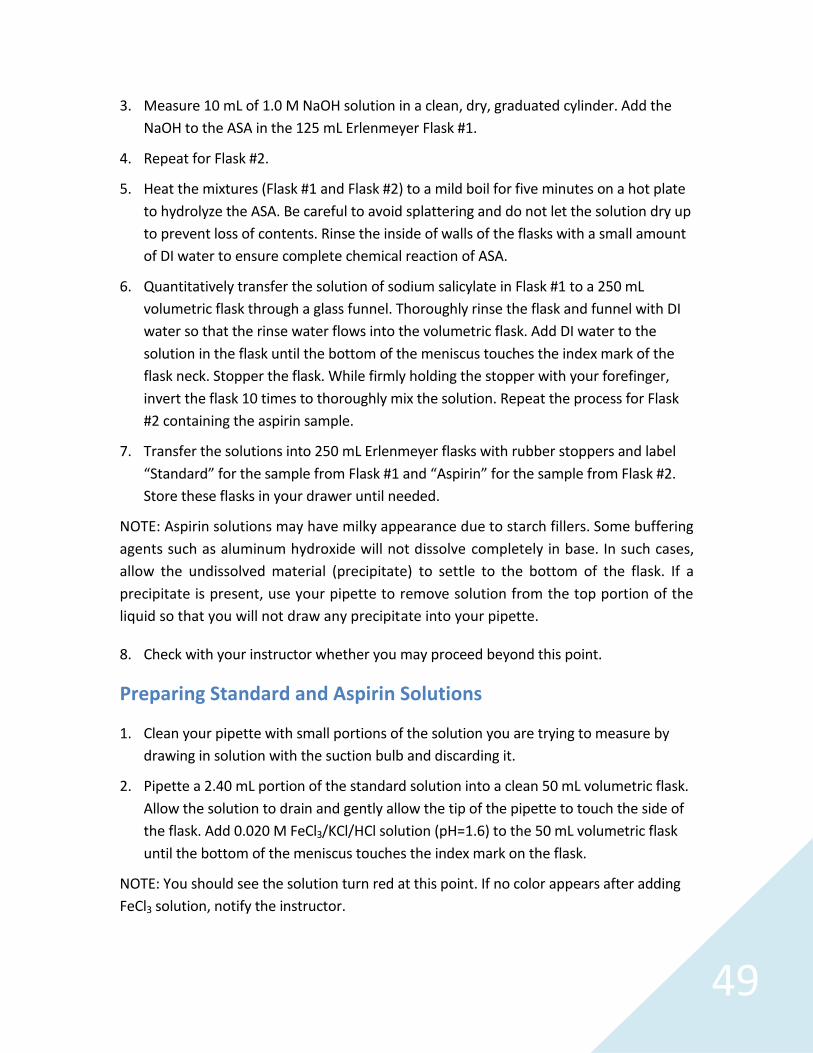
49
3. Measure 10 mL of 1.0 M NaOH solution in a clean, dry, graduated cylinder. Add theNaOH to the ASA in the 125 mL Erlenmeyer Flask #1.
4. Repeat for Flask #2.
5. Heat the mixtures (Flask #1 and Flask #2) to a mild boil for five minutes on a hot plateto hydrolyze the ASA. Be careful to avoid splattering and do not let the solution dry upto prevent loss of contents. Rinse the inside of walls of the flasks with a small amountof DI water to ensure complete chemical reaction of ASA.
6. Quantitatively transfer the solution of sodium salicylate in Flask #1 to a 250 mLvolumetric flask through a glass funnel. Thoroughly rinse the flask and funnel with DIwater so that the rinse water flows into the volumetric flask. Add DI water to thesolution in the flask until the bottom of the meniscus touches the index mark of theflask neck. Stopper the flask. While firmly holding the stopper with your forefinger,invert the flask 10 times to thoroughly mix the solution. Repeat the process for Flask#2 containing the aspirin sample.
7. Transfer the solutions into 250 mL Erlenmeyer flasks with rubber stoppers and label“Standard” for the sample from Flask #1 and “Aspirin” for the sample from Flask #2.Store these flasks in your drawer until needed.
NOTE: Aspirin solutions may have milky appearance due to starch fillers. Some bufferingagents such as aluminum hydroxide will not dissolve completely in base. In such cases,allow the undissolved material (precipitate) to settle to the bottom of the flask. If aprecipitate is present, use your pipette to remove solution from the top portion of theliquid so that you will not draw any precipitate into your pipette.
8. Check with your instructor whether you may proceed beyond this point.
Preparing Standard and Aspirin Solutions
1. Clean your pipette with small portions of the solution you are trying to measure bydrawing in solution with the suction bulb and discarding it.
2. Pipette a 2.40 mL portion of the standard solution into a clean 50 mL volumetric flask.Allow the solution to drain and gently allow the tip of the pipette to touch the side ofthe flask. Add 0.020 M FeCl3/KCl/HCl solution (pH=1.6) to the 50 mL volumetric flaskuntil the bottom of the meniscus touches the index mark on the flask.
NOTE: You should see the solution turn red at this point. If no color appears after addingFeCl3 solution, notify the instructor.

50
3. Stopper the flask. While firmly holding the stopper, with your forefinger, invert theflask 10 times to thoroughly mix the solution. Label this flask “Standard Solution A.”
4. Repeat Steps 2 and 3 to prepare Standard Solutions B, C, D and E by diluting 2.00,1.60, 1.00, 0.40 mL portions of the sodium salicylate standard solution with theFeCl3/KCl/HCl solution.
5. Transfer the Standard Solutions to large test tubes with stoppers and label themclearly.
6. Prepare two unknown aspirin solutions. Use a clean, well-rinsed pipette, transfer 1.20mL of the aspirin stock solution into a 50 mL volumetric flask and dilute it to the markwith 0.020 M FeCl3/KCl/HCl solution. Mix thoroughly as described in Step 3. Make asecond unknown aspirin sample using 1.60 mL of the aspirin stock solution. Transferthe unknown aspirin solutions to large test tubes with stoppers and label them clearly.
Measuring the % Transmittance using a Spectrometer
1. Connect the spectrometer to your computer using the USB cable and turn on yourlight source. If you are using a direct attach light source, start the OceanView softwareand click the Strobe/Lamp Enable box in the Acquisition Group Window to turn thelamp on.
2. Allow the spectrometer and light source to warm up for at least 15 minutes beforeproceeding.
3. If you have not already done so, start OceanView. Click the Start button, then select
All Programs | Ocean Optics | OceanView | OceanView or use the Desktopshortcut created when you installed the software.
4. Select the Spectroscopy Application Wizards option on the Welcome Screen.

51
5. Select the Transmission option in the Spectroscopy Wizards window to start theTransmission Wizard.
6. Select the Active Acquisition (Recommended) option and follow the steps throughthe Wizard to optimize the acquisition parameters for the spectrometer and acquirebackground and reference spectra for your transmission measurement.
7. Fill a cuvette ~⅔ full with the solvent (FeCl3/KCl/HCl solution) to serve as a blank.Place the cuvette in the cuvette holder and set your acquisition parameters in the SetAcquisition Parameters window.
a. Click the Automatic button to automatically adjust theIntegration Time to the optimum value.

52
8. Set Scans to Average to 10 and Boxcar Width to 5 to reduce measurement noise andimprove the measurement. You can set the Scans to Average to a higher value butthis will slow down your acquisitions (total measurement time equals number ofaverages times the integration time).
9. Place a checkmark in the Nonlinearity Correction box if this feature is available foryour spectrometer.
10. Click Next.
11. Click the Store Reference (yellow light bulb) to store a reference spectrum. Click Next.
12. For direct attach light sources, click the Strobe/Lamp Enable box to close the shutterof the light source for your Background measurement. For other light sources, blockthe light from entering the spectrometer (do not turn your light source off). Click theStore Background (gray light bulb) button to store a background spectrum.
13. If you are using a direct attach light source, click the Strobe/Lamp Enable box to openthe shutter. Click Finish. You are now ready to generate transmission spectra.
14. The Transmission spectra will be displayed in the TransmissionView window. You can
adjust the graph appearance using the graph tools above the
transmission graph. Click the Scale Graph Height to Fill Window button to zoom inon the absorbance spectra.
15. Click anywhere on the graph to place a cursor on the graph. Position the cursor at 530nm and record the percent transmittance (%T) of the standard solutions A, B, C, D andE and of the two unknown aspirin solutions. Record the %T values on Data Sheets 1and 2.
NOTE: Your aspirin sample solutions should have % Transmittance between 30% and 70%.If not, make appropriate dilutions or additions so that they fall within the range.Remember to record the dilution or addition factor used to prepare your aspirin sample ifyou decide to adjust your concentration.

53
16. You can save your absorbancespectrum by clicking theConfigure Graph Saving button
to configure the FileWriter.
a. Select the directory whereyou want to save the file.
b. Enter a filename for yourspectrum.
c. Click Apply and then Exit toclose the dialog box.
17. Click the Save Graph to Files button to save your absorbance spectrum.
18. You can overlay your spectrum by clicking the Convert Active Spectrum to Overlay
button to create an overlay of the spectrum in your graph view.
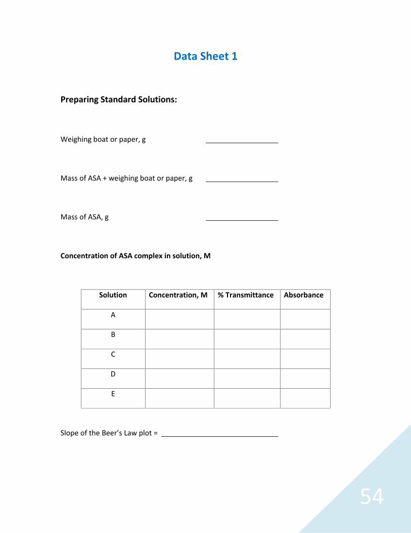
54
Data Sheet 1
Preparing Standard Solutions:
Weighing boat or paper, g
Mass of ASA + weighing boat or paper, g
Mass of ASA, g
Concentration of ASA complex in solution, M
Solution Concentration, M % Transmittance Absorbance
A
B
C
D
E
Slope of the Beer’s Law plot =
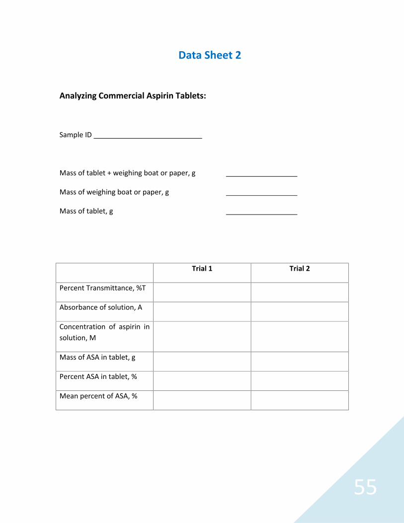
55
Data Sheet 2
Analyzing Commercial Aspirin Tablets:
Sample ID
Mass of tablet + weighing boat or paper, g
Mass of weighing boat or paper, g
Mass of tablet, g
Trial 1 Trial 2
Percent Transmittance, %T
Absorbance of solution, A
Concentration of aspirin insolution, M
Mass of ASA in tablet, g
Percent ASA in tablet, %
Mean percent of ASA, %

56
Calculations
1. Find the slope (k) from your Beer’s Law plot.
2. Convert the percent transmittance (%T) to the equivalent absorbance (A) using:
A = -log (It/Io) = -log T = -log (%T/100) = -log (%T) + 2 = 2 - log (%T)
3. From the calculated absorbance and the Beer’s Law plot slope (k), determine theconcentration of ASA in your aspirin solution using:
c = A/k
4. Calculate the mass of ASA in each tablet, using:
Mass of ASA in grams = [ASA]*(180.2 g /mol ASA)(0.0500 L)(250 mL/1.60 mL)
* ... Use your experimental values of [ASA] in mole/L and the volume of the “original”aspirin solution in mL.
5. Find the percent ASA in each tablet, using :
% ASA in tablet = (mass ASA in tablet, g/ mass of tablet, g) x 100%
6. Calculate the mean percent ASA in your commercial brand of aspirin, using:
Mean % ASA per tablet ={[ ASA (trial #1)] + [% ASA (trial#2)] }/2
57
Post-Lab Questions
1. Explain why the Fe3+/H+ solution was used as a reference solution. Suggest aprocedure you could follow to determine whether it was necessary to use thesolution as a reference or whether de-ionized water would have been satisfactory.
2. Most commercial aspirins claim to contain 5.0 grains of ASA per tablet, where agrain is an old apothecary unit of measurement for mass, equal to 65 mg. Compareyour calculated value of ASA per tablet with respect to the advertised value (i.e., 5.0grains) and determine the percent error.
3. Compare the results of the class data, if available, for different commercial brands ofaspirin. Is there any difference between the different brands of aspirin? Supportyour answer using simple statistics.

58
Spectrophotometric Characterization ofSpice Extracts
Spices have a long and rich history around the world. In some senses (pun intended), thecuisine of a particular region identifies itself with specific local spices. For centuries,spices have been used to modify the flavor of prepared foods, help preserve foods andact as herbal remedies for a wide variety of real and imagined ills.
Along with the important role of contributing to the flavors of foods, spices are alsoemployed to modify the color of foods. Turmeric adds a strong yellow tinge to currieswhile saffron offers a softer yellow to paellas. Paprika contributes a deep, vibrant red tochicken paprikash as well as presenting a vivid, flavorful spice garnish to simple cottagecheese.
In this experiment, you will use isopropanol, also known as rubbing alcohol, to prepareextracts of a selection of spices. You will then use an Ocean Optics spectrometer andlight source to measure the visible light absorbance spectrum of several known spiceextracts. You will then measure unknown spice samples to determine whether or not aspecific spice is present.
Materials
Ocean Optics Flame Spectrometer and direct attach light source-cuvette holder (orstandalone light source, cuvette holder and optical fibers)
Computer with OceanView software installed Spices such as paprika, turmeric, saffron, parsley, jalapeno, cumin and curry 70% isopropanol (rubbing alcohol) Unknown spice solution prepared in 70% isopropanol (rubbing alcohol) 25 mL graduated cylinders 50 mL beakers Transfer/Beral pipettes Cuvettes
Safety
Wear safety goggles and other appropriate safety gear (gloves or apron) during theexperiment. Take all proper safety precautions when handling the solutions.

59
Procedure
1. Place a very small amount of each spice in a 50 mL beaker. Add 20 mL of rubbingalcohol (70% isopropanol). Swirl each beaker to mix the spices. Allow the mixtures tosit for 30 minutes so the colorants are well dissolved and any particulate mattersettles to the bottom of the beakers.
2. Connect the spectrometer to your computer using the USB cable and turn on yourlight source. If you are using a direct attach light source, start the OceanView softwareand click the Strobe/Lamp Enable box in the Acquisition Group Window to turn thelamp on.
3. Allow the spectrometer and light source to warm up for at least 15 minutes beforeproceeding.
4. Start the OceanView software. Click the Start button, then select All Programs |
Ocean Optics | OceanView | OceanView or use the Desktop shortcut createdwhen you installed the software.
5. Select the Spectroscopy Application Wizards option on the Welcome Screen.
6. Select the Absorbance (Concentration) option in the Spectroscopy Wizards windowto start the Absorbance Wizard.

60
7. Select the Absorbance only option and follow the steps through the Wizard tooptimize the acquisition parameters for the spectrometer and acquire backgroundand reference spectra for your absorbance measurement.
8. Fill a cuvette ~⅔ full with 70% rubbing alcohol to serve as a blank. Place the cuvette inthe cuvette holder and set your acquisition parameters in the Set AcquisitionParameters window.
a. Click the Automatic button to automatically adjust theIntegration Time to the optimum value.
b. Set Scans to Average to 10 and Boxcar Width to 5 to reduce measurementnoise and improve the measurement. You can set the Scans to Average to ahigher value but this will slow down your acquisitions (measurement timeequals number of averages times the integration time).
c. Place a checkmark in the Nonlinearity Correction box if this feature is availablefor your spectrometer.
d. Click Next.
9. Click the Store Reference (yellow light bulb) to store a reference spectrum. Click Next.
10. For direct attach light sources, click the Strobe/Lamp Enable box to close the shutterof the light source for your Background measurement. For other light sources, blockthe light from entering the spectrometer (do not turn your light source off). Click theStore Background (gray light bulb) button to store a background spectrum.
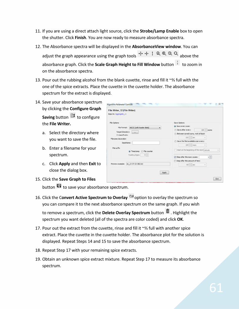
61
11. If you are using a direct attach light source, click the Strobe/Lamp Enable box to openthe shutter. Click Finish. You are now ready to measure absorbance spectra.
12. The Absorbance spectra will be displayed in the AbsorbanceView window. You can
adjust the graph appearance using the graph tools above the
absorbance graph. Click the Scale Graph Height to Fill Window button to zoom inon the absorbance spectra.
13. Pour out the rubbing alcohol from the blank cuvette, rinse and fill it ~⅔ full with theone of the spice extracts. Place the cuvette in the cuvette holder. The absorbancespectrum for the extract is displayed.
14. Save your absorbance spectrumby clicking the Configure Graph
Saving button to configurethe File Writer.
a. Select the directory whereyou want to save the file.
b. Enter a filename for yourspectrum.
c. Click Apply and then Exit toclose the dialog box.
15. Click the Save Graph to Files
button to save your absorbance spectrum.
16. Click the Convert Active Spectrum to Overlay option to overlay the spectrum soyou can compare it to the next absorbance spectrum on the same graph. If you wish
to remove a spectrum, click the Delete Overlay Spectrum button . Highlight thespectrum you want deleted (all of the spectra are color coded) and click OK.
17. Pour out the extract from the cuvette, rinse and fill it ~⅔ full with another spiceextract. Place the cuvette in the cuvette holder. The absorbance plot for the solution isdisplayed. Repeat Steps 14 and 15 to save the absorbance spectrum.
18. Repeat Step 17 with your remaining spice extracts.
19. Obtain an unknown spice extract mixture. Repeat Step 17 to measure its absorbancespectrum.
62
20. Before you exit OceanView, print copies of the absorbance spectrum graphs for eachof your spice extracts and your unknown spice mixture by clicking the Print button
. Alternately, keep OceanView running and use it to compare your unknownsolutions to your known spice spectra.
Data and Analysis
1. Print a copy of the absorbance spectrum for each of the spice extracts that you tested,as well as the unknown spice mixture. Note the distinguishing characteristics of thespectra that will help you identify the unknown.
2. Which spice, or spices, is contained in your unknown? Explain.
3. If distilled water had been used as the calibration blank for the chlorophyll test, wouldit have affected the absorbance measurements?


![Research Article EVALUATION OF ANTI-INFLAMMATORY … · Percentage inhibition= [(absorbance of blank – absorbance of sample)/(absorbance of blank)]×100 1 In-vitro anti-inflammatory](https://static.fdocuments.us/doc/165x107/5e832a1607bd17145979ab05/research-article-evaluation-of-anti-inflammatory-percentage-inhibition-absorbance.jpg)