Spectral and Geographical Domain Coordination for IMT ... · Spectral and . Geographical. Domain...
10
Spectral and Geographical Domain Coordination for IMT-Advanced Compatibility with Point-to-Point Fixed Service ZAID A. SHAMSAN, THAREK ABD RAHMAN, MUHAMMAD R. KAMARUDIN Wireless Communication Centre (WCC), Faculty of Electrical Engineering Universiti Teknologi Malaysia (UTM) 81310 UTM, Skudai, Johor MALAYSIA [email protected] Abstract: - Frequency intersystem interference is a phenomenon caused by coexistence of multiple wireless systems in same or adjacent areas. Consequently, frequency sharing studies play a very important rule in order to use limited spectrum resources efficiently. Because an International Mobile Telecommunication-Advanced (IMT-Advanced) systems are going to use 3500 MHz according to World Radiocommunication Conferences 2007 (WRC-07) decision along with point-to-point Fixed Wireless Access (FWA) system, which currently allocated in the same band, the frequency sharing between IMT-Advanced and FWA is essential. This paper investigates the spectrum sharing requirements in different terrestrial areas using interference to noise ratio criterion. Three methods of investigation of the interference, co-channel, null-guard band, and adjacent channel, have been proposed to investigate the phenomenon in the frequency and space domains to obtain correlation between the minimum separated range of base stations antennas and the frequency separation. Off- axis angles direction alignment is also proposed to reduce the necessary coordination separation distance and frequency separation for good enough coexistence between systems. Key-Words: - Zero-guard band, Co-channel, Adjacent channel, Interference, I/N ratio, Separation distance, Off-axis angles direction alignment. 1 Introduction It is predicte that the development of International Mobile Telecommunications-2000 (IMT-2000) will reach a limit of around 30Mbps [1]. IMT-Advanced is a concept from the International Telecommunications Union (ITU) for mobile communication systems with capabilities which go more beyond than that of IMT-2000. IMT-Advanced was previously known as “systems beyond IMT- 2000” [2]. In the vision of the ITU, IMT-Advanced as a new wireless access technology may be developed around the year 2011 capable of supporting even higher data rates with high mobility, which could be widely deployed about 6 years (from now) in some countries. The targeted capabilities of these IMT-Advanced systems are envisioned to handle a wide range of supported carrier bandwidth: 20MHz up to 100MHz and data rates with target peak data rates of up to approximately 100 Mbps for high mobility such as mobile access and up to say 1 Gbps for low mobility such as nomadic/local wireless access [2]. However, initially scalable bandwidths from 5 to 20MHz will be supported. As a result of the work performed within ITU-R Working Party 8F (WP8F), the frequency band of 3400-3600 MHz has been identified as one of the allocated bands for the future development IMT- Advanced services [3]. This band is already being used for Fixed Wireless Access (FWA) systems in many countries around the world. Therefore, the spectrum allocation should be preceded by sharing and coexistence studies between FWA and IMT- Advanced systems on co-primary basis. From a technical point of view, spectrum sharing studies and analysis aim to identify technical or/and operational compatibilities that will enable radio services to operate in the same or adjacent frequency bands without causing unacceptable interference to each other. Repeatedly, sharing becomes possible when limits are placed on certain system parameters - for example, antenna height, transmission power or antenna pointing. The 3500 MHz frequency band is characterized by excellent features [4-6] such as, lower atmospheric absorption, high degree of reliability, wide coverage, and low rain attenuation particularly in tropical geographical areas. Some of recent coexistence studies which were carried out in the band (3.5 GHz) are in [4, 7-10]. In [7], BWA system represented by FWA is studied to share the same band with point-to-point fixed link system also to WSEAS TRANSACTIONS on SYSTEMS Zaid A. Shamsan, Tharek Abd Rahman, Muhammad R. Kamarudin ISSN: 1109-2777 845 Issue 7, Volume 8, July 2009
Transcript of Spectral and Geographical Domain Coordination for IMT ... · Spectral and . Geographical. Domain...

Spectral and Geographical Domain Coordination for IMT-Advanced
Compatibility with Point-to-Point Fixed Service
ZAID A. SHAMSAN, THAREK ABD RAHMAN, MUHAMMAD R. KAMARUDIN
Wireless Communication Centre (WCC), Faculty of Electrical Engineering
Universiti Teknologi Malaysia (UTM)
81310 UTM, Skudai, Johor
MALAYSIA
Abstract: - Frequency intersystem interference is a phenomenon caused by coexistence of multiple wireless
systems in same or adjacent areas. Consequently, frequency sharing studies play a very important rule in order
to use limited spectrum resources efficiently. Because an International Mobile Telecommunication-Advanced
(IMT-Advanced) systems are going to use 3500 MHz according to World Radiocommunication Conferences
2007 (WRC-07) decision along with point-to-point Fixed Wireless Access (FWA) system, which currently
allocated in the same band, the frequency sharing between IMT-Advanced and FWA is essential. This paper
investigates the spectrum sharing requirements in different terrestrial areas using interference to noise ratio
criterion. Three methods of investigation of the interference, co-channel, null-guard band, and adjacent
channel, have been proposed to investigate the phenomenon in the frequency and space domains to obtain
correlation between the minimum separated range of base stations antennas and the frequency separation. Off-
axis angles direction alignment is also proposed to reduce the necessary coordination separation distance and
frequency separation for good enough coexistence between systems.
Key-Words: - Zero-guard band, Co-channel, Adjacent channel, Interference, I/N ratio, Separation distance,
Off-axis angles direction alignment.
1 Introduction It is predicte that the development of International
Mobile Telecommunications-2000 (IMT-2000) will
reach a limit of around 30Mbps [1]. IMT-Advanced
is a concept from the International
Telecommunications Union (ITU) for mobile
communication systems with capabilities which go
more beyond than that of IMT-2000. IMT-Advanced
was previously known as “systems beyond IMT-
2000” [2]. In the vision of the ITU, IMT-Advanced
as a new wireless access technology may be
developed around the year 2011 capable of
supporting even higher data rates with high
mobility, which could be widely deployed about 6
years (from now) in some countries. The targeted
capabilities of these IMT-Advanced systems are
envisioned to handle a wide range of supported
carrier bandwidth: 20MHz up to 100MHz and data
rates with target peak data rates of up to
approximately 100 Mbps for high mobility such as
mobile access and up to say 1 Gbps for low mobility
such as nomadic/local wireless access [2]. However,
initially scalable bandwidths from 5 to 20MHz will
be supported.
As a result of the work performed within ITU-R
Working Party 8F (WP8F), the frequency band of
3400-3600 MHz has been identified as one of the
allocated bands for the future development IMT-
Advanced services [3]. This band is already being
used for Fixed Wireless Access (FWA) systems in
many countries around the world. Therefore, the
spectrum allocation should be preceded by sharing
and coexistence studies between FWA and IMT-
Advanced systems on co-primary basis.
From a technical point of view, spectrum sharing
studies and analysis aim to identify technical or/and
operational compatibilities that will enable radio
services to operate in the same or adjacent frequency
bands without causing unacceptable interference to
each other. Repeatedly, sharing becomes possible
when limits are placed on certain system parameters
- for example, antenna height, transmission power or
antenna pointing.
The 3500 MHz frequency band is characterized by
excellent features [4-6] such as, lower atmospheric
absorption, high degree of reliability, wide coverage,
and low rain attenuation particularly in tropical
geographical areas. Some of recent coexistence
studies which were carried out in the band (3.5
GHz) are in [4, 7-10]. In [7], BWA system
represented by FWA is studied to share the same
band with point-to-point fixed link system also to
WSEAS TRANSACTIONS on SYSTEMS Zaid A. Shamsan, Tharek Abd Rahman, Muhammad R. Kamarudin
ISSN: 1109-2777 845 Issue 7, Volume 8, July 2009

determine the minimum separation distance and
frequency separation. In this paper, different
geographical deployment areas which are dense
urban, urban, suburban, and rural area are analyzed
to see the required intersystem interference
requirements between two systems. Depending on
systems specifications, spectral emission mask, free
space and clutter loss propagation model, and
frequency offsets from the carrier frequency, various
geographical areas are proposed to study their
effects on spectrum sharing of the band 3.5 GHz.
Mobile Worldwide Interoperability for Microwave
Access (WiMAX) is one the candidate technology
for IMT-Advanced systems; therefore some
parameters of WiMAX will be used instead of IMT-
Advanced which are not officially released.
The reminder of this paper is structured as follows:
In Sections 2 and 3, the intersystem interference and
coexistence model will be presented and includes
sharing criterion, interference assessment and
coexistence wave propagation model. Coexistence
scenarios, parameters and used assumptions will be
presented in Section 4. In Section 5, intersystem
interference scenarios and simulation results will be
made. Finally, the paper conclusions are presented
in Section 6.
2 Intersystem Interference Signal interference is a phenomenon which usually
occurs as a result of overlapping frequencies sharing
the same physical environment at the same time
with overlapping antenna patterns which leads to
capacity loss and coverage limitation. In a single
system, the main type of interference is intra-system
interference, while if two systems coexist in the
same geographical area and using the same
frequency or an adjacent frequency, the interference
is called intersystem interference [11-16]. Many
factors may influence the capability of two systems
to coexist while operating in co-frequency and
adjacent frequency bands. These include lack of
RF isolation, RF front-end filters’ imperfections
(transmitter out-of-band emission level, and receiver
selectivity), antenna polarization, interference
cancellation techniques, and deployment factors,
which results in the performance level degradation
of one or both systems [17-22].
3 Coexistence Model
3.1 Interference Criterion The two systems can peacefully coexiste if the
sharing fundamental criterion is achieved. The
coexistence and interference protection criteria can
be defined as an absolute interference power level I,
interference-to-noise power ratio I/N, or carrier-to-
interfering signal power ratio C/I [23]. ITU-R
Recommendation F.758-2 details two generally
accepted values for the interference–to–thermal-
noise ratio (I/N) for long-term interference into fixed
service receivers. This approach provides a method
for defining a tolerable limit that is independent of
most characteristics of the victim receiver, apart
from noise figure. Each fixed service accepts a 1 dB
degradation (i.e., the difference in decibels between
carrier-to-noise ratio (C/N) and carrier to noise plus
interference ratio C/(N + I)) in receiver sensitivity.
The main scenarios, co-channel interference, zero-
guard band interference, and adjacent channel
interference can be considered for sharing studies.
An I/N of –6 dB is the fundamental criterion for
coexistence [23-25], so it should be:
NI (1)
Where I and N are the interference level at victim
receiver and thermal noise floor of receiver,
respectively, in dBm. α is the protection ratio in dB.
The protection value of -6 dB means that the
interference must be approximately 6 dB below
thermal noise. This value [29] can be justified as
follows,
dBdBN
I
N
I
N
IN
INC
NC
dBdBIN
CN
C
0.6
26.0
26.1
rat io)aas(26.1
1
(2)
3.2 Interference Assessment The interference level from co-channel or adjacent
channel scenario is given be:
LossesCorr_bandΔfMaskGrGtPtΔfI
(3)
WSEAS TRANSACTIONS on SYSTEMS Zaid A. Shamsan, Tharek Abd Rahman, Muhammad R. Kamarudin
ISSN: 1109-2777 846 Issue 7, Volume 8, July 2009

Where Pt is the transmitted power of the interferer
in dBm, Gt and Gr are the gains of the interferer
transmitter antenna and the victim receiver antenna
in dBi, respectively. Mask(∆f) represents attenuation
of adjacent frequency due to mask where ∆f is the
difference between the carriers of interferer and the
victim. Mask(∆f) is defined as the spectral power
density mask within a typically 250 % of the
relevant channel separation (ChS) which is not
exceeded under any combination of service
types and any loading. The attenuation due to
normalized mask is derived by using the equations
of a straight line as follow:
5.0250
206.177.1238
06.171.014.1732
71.05.029.1148
5.08
5.000
fdB
fdBk
fdBk
fdBk
fdB
fdB
fW iMAX
Mask
(4)
5.0250
206.115.1932
06.171.029.1427
71.05.048.908
5.08
5.000
fdB
fdBk
fdBk
fdBk
fdB
fdB
fFW A
Mask
(5)
Where 01.0 kk .
Corr_band denotes correction factor of band ratio
and depends on bandwidth of interferer and victim,
where
victimBW
erfererBWifd
victimBW
erfererBW
victimBW
erfererBWifd
bandorr
int)
intlog(10
int0
_C
B
B
(6)
Losses is the attenuation due to the propagation in
free space and clutter loss as shown in (10).
3.3 Noise and Thermal Noise Floor
Assessment Electronic circuits and receivers are affected by a
variety of noise sources. In terms of electronic
receivers, noise can be separated into two groups:
thermal noise (also called internal noise, caused by
electronic devices themselves), and the
environmental noise (atmospheric, cosmic, man-
made, etc.). Thermal noise is a function of a random
movement of particles in the medium in which the
signal is travelling. Roughly speaking, thermal noise
dominates the other sources for frequencies above
few hundred MHz. Therefore, noise-limited
electronic detection can be grouped into thermal-
noise-limited detection (e.g., microwave receivers)
and environmentally noise-limited detection (e.g.,
HF receivers, in the 3-30 MHz band) Thermal noise
of a receiver is typically referred to the chain in the
form of either system noise temperature or noise
figure Characteristics of the noise specify the noise
spectral density. The noise power (floor), i.e., the
minimum signal-detection limit, is equal to the
bandwidth multiplied by the noise spectral density.
Thermal noise is directly proportional to the receiver
bandwidth, and can be calculated as
N=kTB [watt] (7)
Where
B= noise bandwidth [Hz]
k=Boltzman's constant = 1.38×10⁻²³
J/oK
T = temperature in degrees Kelvin K.
Thermal noise can be considered to be white noise
(i.e., having a Gaussian amplitude distribution and a
flat power spectral density, S (f) =kT). Since
kT[dB]=-204 dBW/Hz at 300 oK, thermal noise can
also be calculated as
HzdBBWN 204 [dB] (8)
For example, the noise floor for 10 kHz FM, 2 MHz
commercial GPS, and 6 MHz TV channels are N =-
l34dBm, N=-111 dBm, and N=-106 dBm,
respectively. Where (X dB = X + 30 dBm).
As a decibel scale, the thermal noise floor of
receiver can be expressed as (9) and it depends on
noise figure and bandwidth of victim receiver.
victim
BWNFN10
log10174 (9)
Where NF is noise figure of receiver in dB and
WSEAS TRANSACTIONS on SYSTEMS Zaid A. Shamsan, Tharek Abd Rahman, Muhammad R. Kamarudin
ISSN: 1109-2777 847 Issue 7, Volume 8, July 2009
BWvictim represents victim receiver bandwidth in
Hz.
Increasing the noise floor by even a few dB may
adversely affect existing licensed systems and their
customers in a number of ways, such as: (1)
coverage, (2) system capacity, (3) reliability of data
throughput, and (4) quality of service (QoS). It is
found that a wireless access system employing
measurement-based interference avoidance must
detect energy of fixed wireless access and WiMAX
transmissions far below the thermal noise floor of
the wireless access system receivers. However, this
would increase receiver complexity such that
interference from all other users will cause no more
than 1 dB degradation to the fixed wireless access
and WiMAX receiver threshold
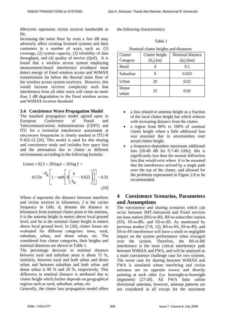
3.4 Coexistence Wave Propagation Model The standard propagation model agreed upon in
European Conference of Postal and
Telecommunications Administrations (CEPT) and
ITU for a terrestrial interference assessment at
microwave frequencies is clearly marked in ITU-R
P.452-12 [26]. This model is used for this sharing
and coexistence study and includes free space loss
and the attenuation due to clutter in different
environments according to the following formula:
33.0625.06tanh125.10
log20log205.92
ah
hkd
e
fdLosses
(10)
Where d represents the distance between interferer
and victim receiver in kilometers, f is the carrier
frequency in GHz. dk denotes the distance in
kilometers from nominal clutter point to the antenna,
h is the antenna height in meters above local ground
level, and ha is the nominal clutter height in meters
above local ground level. In [26], clutter losses are
evaluated for different categories: trees, rural,
suburban, urban, and dense urban, etc. The
considered four clutter categories, their heights and
nominal distances are shown in Table 1.
The percentage decrease in nominal distance
between rural and suburban areas is about 75 %,
similarly, between rural and both urban and dense
urban and between suburban and both urban and
dense urban is 80 % and 20 %, respectively. This
difference in nominal distance is attributed due to
clutter height which further depends on geographical
regions such as rural, suburban, urban, etc.
Generally, the clutter loss propagation model offers
the following characteristics:
Table 1
Nominal clutter heights and distances
Clutter
Category
Clutter height
(ha) (m)
Nominal distance
(dk) (km)
Rural 4 0.1
Suburban 9 0.025
Urban 20 0.02
Dense
urban 25 0.02
a loss related to antenna height as a fraction
of the local clutter height but which reduces
with increasing distance from the clutter.
a region from 80% to 100% of nominal
clutter height where a little additional loss
was assumed due to uncertainties over
actual clutter height.
a frequency-dependent maximum additional
loss (20-40 dB for 0.7-40 GHz); this is
significantly less than the normal diffraction
loss that would exist where it to be assumed
that the interference arrived by a single path
over the top of the clutter, and allowed for
the problems represented in Figure 2.8 to be
recommended.
4 Coexistence Scenarios, Parameters
and Assumptions The coexistence and sharing scenarios which can
occur between IMT-Advanced and Fixed services
are base station (BS)-to-BS, BS-to-subscriber station
(SS), SS-to-BS, and SS-to-SS. As mentioned by
previous studies [7-8, 12], BS-to-SS, SS-to-BS, and
SS-to-SS interference will have a small or negligible
impact on the system performance when averaged
over the system. Therefore, the BS-to-BS
interference is the most critical interference path
between WiMAX and FWA, and will be analyzed as
a main coexistence challenge case for two systems.
The worst case for sharing between WiMAX and
FWA is simulated where interfering and victim
antennas are on opposite towers and directly
pointing at each other (i.e. boresight-to-boresight
alignment) [27-28]. All FWA links utilize
directional antennas, however, antenna patterns are
not considered at all except for the maximum
WSEAS TRANSACTIONS on SYSTEMS Zaid A. Shamsan, Tharek Abd Rahman, Muhammad R. Kamarudin
ISSN: 1109-2777 848 Issue 7, Volume 8, July 2009

antenna gain in link budget, so it is assumed they are
considered as omnidirectional in order to study the
worst case scenario. The BSs parameters of two
systems are detailed in Table 2 and formulas (1)-
(10). Spectral emission mask Type-G European
Telecommunications Standardization Institute
standard EN 301021 (Type-G ETSI-EN301021) [4]
is applied to interference from WiMAX, while
Type-F ETSI-EN301021 [4] is applied when
WiMAX is victim and FWA is interferer.
Figure 1 depicts the spectrum emission mask
overlapping between 5 MHz WiMAX channel
bandwidth as an Interfering transmitter and 7 MHz
point-to-point FWA channel bandwidth. In this case,
the bandwidth overlapping correction factor gives a
value of zero decibel because the interferer
bandwidth is greater than that of the victim receiver.
While Figure 2 depict the spectrum emission mask
overlapping between 10 MHz WiMAX channel
bandwidth as an Interfering transmitter and 7 MHz
point-to-point FWA channel bandwidth. A 1.5 dB
loss in the power of interfering signal is occurred as
a result for this overlapping.
Figure 1. Bandwidth overlapping between 5 MHz
WiMAX channel bandwidth as an interferer and 7
MHz FWA channel bandwidth as a victim
5 Results and Discussions
5.1 Different Antenna Heights and Terrestrial
Area Effects
It can be extracted from Figs. 3-5 that antenna
height has a great effect on the coexistence scenario
and thus the required minimum separation distance
for the same interference scenario varies according
to change in antenna height. Any increase in
separation distance between systems in a
deployment area for an interference scenario can be
compensated by decreasing or increasing the
antenna height in another deployment area in order
Figure 2. Bandwidth overlapping between 10 MHz
WiMAX channel bandwidth as an interferer and 7
MHz FWA channel bandwidth as a victim
Table 2
WiMAX and FWA systems parameters used
Parameter
Value
WiMAX FWA
Center frequency of
operation (MHz) 3500 3500
Bandwidth
(MHz) 10 7
Base station transmitted
power (dBm) 43 35
Spectral emissions mask
requirements
ETSI-EN301021
Type G Type F
Base station antenna
gain (dBi) 18 17
Base station antenna
height (m) Up to 30
Up to
30
Noise figure of base
station (dB) 4 5
WSEAS TRANSACTIONS on SYSTEMS Zaid A. Shamsan, Tharek Abd Rahman, Muhammad R. Kamarudin
ISSN: 1109-2777 849 Issue 7, Volume 8, July 2009

to fulfill coexistence requirements. These figures
also inform that at very short antenna height
(approximately up to one and half meter especially
in dense urban, urban, and suburban areas) and at
high antenna height (approximately higher than 29
m) all deployment areas provide same coexistence
conditions and requirements with respect to distance
and frequency separation.
0 2000 4000 6000 8000 100000
5
10
15
20
25
30
FW
A s
erv
ice B
S a
nte
nn
a h
eig
ht
(m)
Minimum separation distance (km)
Dense urban area
Urban area
Suburban area
Rural area
Figure 3. Minimum required distance versus antenna
height of FWA in dense urban, urban, suburban, and
rural areas for co-channel interference scenario
0 50 100 150 2000
5
10
15
20
25
30
FW
A s
erv
ice B
S a
nte
nn
a h
eig
ht
(m)
Minimum separation distance (km)
Dense urban area
Urban area
Suburba area
Rural
Figure 4. Minimum required distance versus antenna
height of FWA in dense urban, urban, suburban and
rural areas for zero-guard band interference scenario
Co-channel interference scenario within rural area is
the most difficult scenario among other scenarios
due to its need to a long coordination distance in the
range 9920 km and 9941 km at 5 m and 25 m
antenna height, respectively.
Meanwhile, adjacent channel interference scenario
with frequency offset from the carrier of 20 MHz in
dense urban area shows the best coexistence
scenario, for example, it needs 3.25 km and 30.7 km
geographical separation at 5 m and 25 m antenna
height, respectively.
0 5 10 15 20 25 30 350
5
10
15
20
25
30
FW
A s
erv
ice B
S a
nte
nn
a h
eig
ht
(m)
Minimum separation distance (km)
Dense urban area
Urban area
Suburban area
Rural area
Figure 5. Minimum required distance versus antenna
height of FWA in dense urban, urban, suburban, and
rural areas for adjacent channel interference scenario
5.2 Different Channel Bandwidth Effects
In Fig. 6, the minimum separation distance in dense
urban areas versus frequency separation from the
carrier frequency is summarized for the three
selected channel BW of WiMAX service. The
results indicate that the required distance and
frequency separation increase as interference
bandwidth increases and vice versa. From Fig. 6, in
order to initiate the operation of WiMAX and FWA
simultaneously, the frequency offset has to be larger
than half of the interferer nominal system BW. For
example, for 5 MHz WiMAX channel BW it should
be larger than 2.5 MHz. Frequency offset less than
that would require very high separation distances.
Furthermore, Fig. 6 verifies that the required
separation distance goes more rapidly to be
significantly smaller when the maximum frequency
offset exceeds double of the interferer nominal
system bandwidth.
5.3 Antenna Discrimination Effects
The resultant separation distances values are too
large to be practically realizable especially in case
co-channel intersystem interference. However, in
WSEAS TRANSACTIONS on SYSTEMS Zaid A. Shamsan, Tharek Abd Rahman, Muhammad R. Kamarudin
ISSN: 1109-2777 850 Issue 7, Volume 8, July 2009

many cases the path between interferer and victim or
the off-axis discrimination of their antennas may be
sufficient to allow operation at very close proximity
as depicted in Fig. 7.
101
102
103
0
5
10
15
20
25
30
35
40
2.5
Minimum distance between interferer (WiMAX) and victim (FWA) (km)
Fre
qu
en
cy o
ffset
betw
een
carr
iers
(d
B)
5 MHz WiMAX Channel bandwidth
10 MHz WiMAX Channel bandwidth
20 MHz WiMAX Channel bandwidth
Figure 6. Minimum separation distance in dense
urban area versus frequency offsets when WiMAX
is the interferer
Antenna discrimination loss is resultant from the
antenna direction of the interferer transmitter and
victim receiver services which is dependant on the
off axis angles Фi and θv as in Fig. 7. The effect of
resultant loss caused by antenna alignment is
investigated such that different losses ranging from
10 dB to 50 dB are considered. Therefore, required
separation distance for coexistence is decreased as
interferer antenna radiation direction is modified to
be more a way of the victim receiver. Fig. 8
clarifies that the required distance in case co-channel
coexistence by applying 50 dB antenna
discrimination loss for the three WiMAX channel
bandwidths is significantly decreased from 3,147
km, 2632 km, and 1861 km to 9.95 km, 8.324 km,
and 5.886 km for 5, 10 and 20 MHz WiMAX
channel bandwidth, respectively.
Table 3 details the effects of antenna discrimination
on coexistence required distance in dense urban area
when interference falls down from 5 MHz, 10 MHz,
and 20 MHz WiMAX system base station on 7 MHz
FWA system base station. It can be observed that
huge distances are required in case co-channel
interference scenarios for different channel
bandwidth. These distances are reduced to its
minimum values by applying antenna discrimination
as can be seen from Fig. 8. Similarly, the adjacent
channel by guard band of 10 MHz represents a good
situation and it requires a shorter distance than that
of co-channel and zero-guard band. It can also be
noticed that the wider the interfering bandwidth, the
most interference effects
Figure 7: Interference scenario for one interferer
base station to victim station with off axis angles Фi
and θv.
0 500 1000 1500 2000 2500 3000 35000
5
10
15
20
25
30
35
40
45
50
Separation distance between base stations (km)
An
ten
na d
iscri
min
ati
on
lo
ss (
dB
)
5 MHz WiMAX Channel Bandwidth
10 MHz WiMAX Channel Bandwidth
20 MHz WiMAX Channel Bandwidth
Figure 8. Antenna discrimination effects for co-
channel scenario when 5, 10 and 20MHz WiMAX is
the interferer
6 Conclusions Coexistence and intersystem interference
coordination between IMT-Advanced and FWA
systems on co-primary basis is difficult to be
achieved and relies on many factors such as systems
specifications, antenna height, propagation wave
model, geographical area, interference type, etc. In
this paper, spectral emission mask model has been
used with intersystem interference criteria I/N of -6
dB, different interference scenarios and different
receiver antenna heights for estimating the impact of
WSEAS TRANSACTIONS on SYSTEMS Zaid A. Shamsan, Tharek Abd Rahman, Muhammad R. Kamarudin
ISSN: 1109-2777 851 Issue 7, Volume 8, July 2009

interference between IMT-Advanced represented by
WiMAX and FWA service. Comparative simulation
results showed that the separation distance decreases
when the two systems are deployed in dense urban
area while rural area represents a worse case for
coexistence. Moreover, the clutter loss values
present a constant value when the antenna height is
higher than the clutter height, therefore the distance
also become constant. Approximately, the distance
remains constant for antenna height lower than 6 m,
4 m, 2 m, and 0.5 m, and higher than 28 m, 24 m, 11
m, and 5 m in dense urban, urban, suburban and
rural geographical area, respectively. It can be
concluded that the frequency offset has to be larger
than half of the interferer nominal system BW for
coexistence successfully. Frequency offset less than
that would require very high separation distances.
Acknowledgment This research work was supported by
SKMM/RPD/SRPD(2)/SRCP/TC/03/07(7) research
grant. The authors would like to thank the SKMM
and appreciate their kindness, valuable assistance,
and financial supports.
References:
[1] ITU-R M.1645, Framework and overall
objectives of the future development of IMT
2000 and systems beyond IMT 2000,
International Telecommunications Union-
Radiocommunication Sector, 2003.
[2] Z. A. Shamsan, and T. Abd. Rahman,
Coexistence between WiMAX and Existing
FWA Systems in the Band 3500 MHz, in
Proceedings of The International MultiConference
of Engineers and Computer Scientists (IMECS2008), Vol. 2, No. 195, 2008, p.p 1056-
1061.
[3] IST-4-027756 WINNER II, D 5.10.1 v1.0. The
winner role in the ITU process towards IMT-
Advanced and newly identified spectrum. 2007.
[4] Z. A. Shamsan, and T. A. Rahman, Spectrum
sharing studies of IMT-Advanced and FWA
services under different clutter loss and channel
bandwidths effects, Progress In
Electromagnetics Research, PIER 87, 2008, pp.
331-344.
[5] A. D. Panagopoulos, Uplink co-channel and co-
polar interference statistical distribution between
adjacent broadband satellite networks, Progress
In Electromagnetics Research B, Vol. 10,
2008,pp. 17–189.
Table 3
Required Separation Distance with and without
Antenna Discrimination
WiMAX
BW
Coexistence
Mechanism
Antenna
Discrimination
Loss
Guard
band
Separation
Required
Separation
Distance
5 MHz
Co-channel
∆f =0MHz
0 dB -2.5 MHz 3,147 km
20 dB -2.5 MHz 315 km
50 dB -2.5 MHz 9.95 km
Zero-guard
band
∆f =6MHz
0 dB 0 MHz 32.25 km
20 dB 0 MHz 3.225 km
50 dB 0 MHz 0.102 km
Adjacent
Channel
∆f =10MHz
0 dB 4 MHz 9.95 km
20 dB 4 MHz 0.995 km
50 dB 4 MHz 0.032 km
10MHz
Co-channel
∆f =0 MHz
0 dB -7 MHz 2632 km
20 dB -7 MHz 263.2 km
50 dB -7 MHz 8.324 km
Zero-guard
band
∆f =8.5MHz
0 dB 0 MHz 50.15 km
20 dB 0 MHz 5.025 km
50 dB 0 MHz 0.159 km
Adjacent
Channel
∆f =20MHz
0 dB 11.5 MHz 8.324 km
20 dB 11.5 MHz 0.833 km
50 dB 11.5 MHz 0.027 km
20MHz
Co-channel
∆f =0MHz
0 dB -7 MHz 1861 km
20 dB -7 MHz 186.1 km
50 dB -7 MHz 5.886 km
Zero-guard
band
∆f =13.5MHz
0 dB 0 MHz 74.12 km
20 dB 0 MHz 7.418 km
50 dB 0 MHz 0.234 km
Adjacent
Channel
∆f =40MHz
0 dB 26.5 MHz 5.885 km
20 dB 26.5 MHz 0.589 km
50 dB 26.5 MHz 0.019 km
[6] J. S. Mandeep and J. E. Allnutt, Rain attenuation
predictions at Ku-band in south east Asia
countries, Progress In Electromagnetics
Research, PIER 76, 2007, pp. 65–74.
[7] Ofcom, Digital dividend–mobile voice and data
(IMT) issues, MasonCommunications Ltd., 2007.
WSEAS TRANSACTIONS on SYSTEMS Zaid A. Shamsan, Tharek Abd Rahman, Muhammad R. Kamarudin
ISSN: 1109-2777 852 Issue 7, Volume 8, July 2009

[8] CEPT ECC Report 100, Compatibility studies in
the band 3400-3800 MHz between broadband
wireless access (BWA) systems and other
services, ECC within CEPT, Bern, February
2007.
[9] Z. A. Shamsan, A. E. Basheer, W. E. Osman, L.
F. Abdulrazak, T. A.. Rahman, On the Impact of
Channel Bandwidths and Different Deployment
Areas on Spectrum Sharing of Next Wireless
Systems, in Proceedings of IEEE International
Conference on Electronic Design2008
(ICED2008), 2008, pp. 1-5.
[10] Z. A. Shamsan, L. F. Abdulrazak, and T. A.
Rahman, Co-channel and Adjacent Channel
Interference Evaluation for IMT-Advanced
Coexistence with Existing Fixed System, in
Proceedings of IEEE International RF and
Microwave Conference (RFM 2008), 2008, pp.
65-69.
[11] A. Sathyendran, A. R. Murch, and M. Shafi,
Study of inter-system interference between
region one and twocellular systems in the 2 GHz
band. Proceedings of the 48th IEEE Vehicular
Technology Conference, 1998(VTC 98), 2, pp.
1310-1314.
[12] H. Haas, S. McLaughlin, and G.J.R. Povey,
The Effects of Inter-System Interference in
UMTS at 1920 MHz. IEEE International
Conference on 3G Mobile Communication
Technologies. 2000.
[13] I. Tardy, O. Grondalen, and G. Vezzani,
Interference in TDD based LMDS systems”, IST
Mobile and Wireless Summit, Tessaloniki, 17-19
June 2002.
[14] A.D. Panagopoulos, K. P. Liolis, and P. G.
Cottis, Cell-Site Diversity Against Co-Channel
Interference in LMDS Networks. Wireless
Personal Communications Journal, Springer,
Vol. 39, 2006, pp. 183–198.
[15] Z. A. Shamsan, and T. Abd. Rahman,
Simulation Model for Compatibility of Co-Sited
IMT-Advanced and Point to Multipoint Services,
Progress In Electromagnetics Research C, Vol.
6, 2009, pp. 127-144.
[16] Z. A. Shamsan, and T. Abd. Rahman,
Intersystem Interference Scenarios between
Fixed and IMT-Advanced Services in Different
Terrestrial Regions, in Proceedings of IEEE
International Conference on Future Computer
and Communication (ICFCC2009), 2009, pp.
237-240.
[17] W. Jiang, L.Shuangchun, N. Kai, and W.
Weiling, Capacity Loss Due to Coexistence of
WCDMA and CDMA2000 systems,
International Conference on Next Generation
Teletraffic and Wired/Wireless Advanced
Networking (NEW2AN'04), Russia, 2004.
[18] 3GPP TR 25.942 V.7, 3rd
Generation
Partnership Project; Technical Specification
Group Radio Access Networks; Radio
Frequency (RF) system scenarios, 3rd
Generation
Partnership Project Organizational Partners,
2007.
[19] WiMAX Forum, Service Recommendations to
Support Technology Neutral Allocations-
FDD/TDD coexistence, April 2007.
[20] H. Yehia, and H. Kamal, Inter-System
Interference Effect on WiMAX Network
Performance”, Proceeding IEEE 3rd
International Conference on Information and
Communication Technologies: From Theory to
Applications (ICTTA 2008), 2008, pp. 1-6.
[21] Z. A. Shamsan, L. Faisal, T. Abd Rahman, On
Coexistence and Spectrum Sharing Analysis
between IMT-Advanced and FWA Systems,
WSEAS Transaction on Communication,, Volume
7, Issue 5, 2008, pp. 505-515.
[22] Z. A. Shamsan, L. Faisal, S. K. Syed-Yusof,
and T. Abd. Rahman, Spectrum Emission Mask
for Coexistence between Future WiMAX and
Existing Fixed Wireless Access Systems,
WSEAS Transaction on Communication,
Volume 7, Issue 6, 2008, pp. 627-636 .
[23] NTIA Report 05-432, Interference
protection criteria phase 1 - compilation from
existing sources, National Telecommunications
and Information Administration, 2005.
[24] ITU-R M. 2113, Draft new report on sharing
studies in the 2 500-2 690 MHz band between
IMT-2000 and fixed broadband wireless access
(BWA) systems including nomadic applications
in the same geographical area, International
Telecommunications Union-Radiocommunnic-
ation Sector, 2007.
[25] ITU-R F.1402, Frequency sharing criteria
between a land mobile wireless access system
and a fixed wireless access system using the
same equipment type as the mobile wireless
access system, International Telecommunic-
ations Union-Radiocommunnication Sector,
1999.
[26] ITU-R P.452-12, Prediction procedure for the
evaluation of microwave interference between
stations on the surface of the earth at frequencies
above about 0.7 GHz, International
Telecommunications Union-Radiocommunnic-
ation Sector 2005.
[27] Z. A. Shamsan, L. Faisal, and T. Abd.
Rahman, Co-sited and Non Co-sited Coexistence
WSEAS TRANSACTIONS on SYSTEMS Zaid A. Shamsan, Tharek Abd Rahman, Muhammad R. Kamarudin
ISSN: 1109-2777 853 Issue 7, Volume 8, July 2009

Analysis between IMT-Advanced and FWA
Systems in Adjacent Frequency band, in
Proceedings of WSEAS the International
Conference on Telecommunications and
Informatics (TELE-INFO '08), 2008, pp. 44-48.
[28] Z. A. Shamsan, and T. Abd. Rahman, On the
Comparison of Intersystem Interference Scenario
between IMT-Advanced and Fixed Services
over Various Deployment Areas at 3500 MHz,
Progress In Electromagnetics Research C, Vol.
5, 2008, pp. 169-185.
[29] Z. A. Shamsan, and T. Abd. Rahman,
Simulation Model for Compatibility of Co-Sited
IMT-Advanced and Point to Multipoint Services,
Progress In Electromagnetics Research C, Vol.
6, 2009, pp. 127-144.
WSEAS TRANSACTIONS on SYSTEMS Zaid A. Shamsan, Tharek Abd Rahman, Muhammad R. Kamarudin
ISSN: 1109-2777 854 Issue 7, Volume 8, July 2009