
SpecterOS™ 4x - Raytheon ELCAN Optical Technologies
40
Operator’s Manual SpecterOS 4x by ELCAN OPM 009 REV A Lightweight Day Sight 4x Single Field-of-View Optical Sight
Transcript of SpecterOS™ 4x - Raytheon ELCAN Optical Technologies

Operator’s Manual SpecterOS 4x by ELCAN
OPM 009 REV A
Lightweight Day Sight 4x Single Field-of-View Optical Sight

OPM 009 REV A Copyright © 2011 Raytheon ELCAN Optical Technologies
This page intentionally left blank.

OPM 009 REV A Copyright © 2011 Raytheon ELCAN Optical Technologies
TABLE OF CONTENTS CHAPTER 1 GENERAL DESCRIPTION & SPECIFICATIONS 1.1 Description 1
1.2 Technical Specifications (nominal) 4
1.3 Controls and Terminology 6
1.4 Safety 11
CHAPTER 2 PREPARATION FOR USE & INSTALLATION
2.1 Mounting Sight to the Weapon/Eye Relief 12
2.2 Zeroing 14
CHAPTER 3 PRINCIPLES OF OPERATION
3.1 Reticle and Ranging 25
CHAPTER 4 MAINTENANCE
4.1 Preventative Maintenance 28
4.2 Changing the Battery 29
4.3 Cleaning 30
4.4 Replacement Parts 31
4.5 Preparation for Shipment 32
3.2 Reticle Illumination 26

OPM 009 REV A Copyright © 2011 Raytheon ELCAN Optical Technologies
This page intentionally left blank.

TABLE OF FIGURES and TABLES CHAPTER 1 GENERAL DESCRIPTION & SPECIFICATIONS Figure 1-1: Eye Relief 2 Figure 1-2: Overall Views 3
Figure 1-3: Left Side View and Selected Controls 6
Figure 1-4: Right Side View and Selected Controls 7
CHAPTER 2 PREPARATION FOR USE & INSTALLATION
Figure 2-1: Lever lock sight to MIL-STD 1913 rail 12
Figure 2-2: Proper Eye Relief 13
Figure 2-3: Azimuth/Windage Adjusts 17
Figure 2-4: Aimed fire shot group 18
Figure 2-5: Determine approximate center of group 19
Figure 2-6: Adjust Azimuth/Windage or Elevation 20
Figure 2-7: Adjust POI - Azimuth/Windage 21
Figure 2-8: Adjust POI - Elevation 23
Table 2-1: POI Movement per Click of Adjustment 24
CHAPTER 3 PRINCIPLES OF OPERATION Figure 3-1: Reticle (not to scale) 25
Figure 3-2: Sample Illustration of Reticle Detail (not to scale) 25
Figure 3-3: Red Dot and Illumination Ballistic Reticle 27 Figure 3-4: Reticle Illumination Switch Operation 27
CHAPTER 4 MAINTENANCE Figure 4.1 Battery Replacement 29 Table 4-1: Replacement Parts 31
Table 1-1: Technical Specifications (nominal) 4

OPM 009 REV A Copyright © 2011 Raytheon ELCAN Optical Technologies
This page intentionally left blank.

OPM 009 REV A Copyright © 2011 Raytheon ELCAN Optical Technologies
1.1 Description
The SpecterOS 4x Optical Sight provides the shooter with a 4x-magnified sight with a field-of-view of 6°. This magnification allows for long-range target identification and precision marksmanship capability out to 600 meters range by using the bullet drop compensation reticle (graticule).
A red LED is used to illuminate the reticle. When turned in the counter-clockwise direction, the reticle illumination switch provides five illumination levels of a “red dot” aiming mark. The red dot attracts the eye to the precise point of aim and bullet impact. By rotating the switch in the clockwise direction, five levels of illumination for the whole reticle allows dawn to dusk and night shooting of the sight
‘Throw Levers’ attach the sight to the MIL-STD 1913 rail. This lever system provides accurate zero retention when the sight is repeatedly removed and replaced on the rail.
The sight can be fitted with an accessory mount that fits on top of the housing to accommodate a ’mini red dot sight’. An anti-reflection device (ARD) and a laser protection filter are also available as options.
WARNING: Clear and safe the weapon prior to mounting the sight!
CHAPTER 1: GENERAL DESCRIPTION & SPECIFICATIONS
1

OPM 009 REV A Copyright © 2011 Raytheon ELCAN Optical Technologies 2
2 ¾” 70mm
Figure 1-1: Long eye relief
1.1 Description (continued)

OPM 009 REV A Copyright © 2011 Raytheon ELCAN Optical Technologies
1.1 Description (continued)
3
Left Side View
Front View Rear View
Top View
Figure 1-2: Selected Overall Views

OPM 009 REV A Copyright © 2011 Raytheon ELCAN Optical Technologies
1.2 Technical Specifications (nominal)
4
Table 1-1: Technical Specifications (nominal)
Specification
Fixed Magnification 4x (nominal)
Field of View Min 6°
Objective Lens Dia. 32 mm (1.3”)
Exit Pupil Min 7.7mm (0.3”)
Eye Relief 70mm (2 ¾”)
Optical Axis Height 39mm (1.53”)
Zeroing Range ±60 MOA
Mount Compatibility MIL-STD 1913
Length, Width, Height (from rail) 153.1mm x 73mm x 69mm
(6.0” x 2.9” x 2.7”)
Aiming Point 1.5 MOA Dot

OPM 009 REV A Copyright © 2011 Raytheon ELCAN Optical Technologies
1.2 Technical Specifications (nominal - continued)
5
Table 1-1: Technical Specifications (nominal - continued)
Specification
Reticle Pattern 5.56, 7.62 STD
Illumination LED (650nm)
Operating Temp -40 to +65 °C (-40 to 140 °F)
Storage Temp -40 to +71 °C (-40 to 160 °F)
Submersion 2 hours @ 20 m (66 FSW)
Battery / Life DL 1/3 N
Min 300 hrs @ max brightness
Finish Anodized
Mount Attach Dual Levers
Weight 528 g (18.6 oz)

OPM 009 REV A Copyright © 2011 Raytheon ELCAN Optical Technologies
1.3 SpecterOS 4x Controls and Terminology
6
Figure 1-4: Left Side View and Selected Controls
Elevation Adjustment Dial
Reticle Illumination Switch
Rear
Windage/Azimuth Adjustment Dial
Front
MRD Mount Optional

OPM 009 REV A Copyright © 2011 Raytheon ELCAN Optical Technologies
1.3 SpecterOS 4x Controls and Terminology
7
ZERO LOCK
ELEVATION ADJUST
WEAPON MOUNTING LEVERS
Figure 1-4: Right Side View and Selected Controls

OPM 009 REV A Copyright © 2011 Raytheon ELCAN Optical Technologies
1.3.1 Mount Attachment ’Throw Levers’ The throw levers are used to secure the sight to the weapon’s MIL-STD-1913 “Picatinny” rail. The SpecterOS 4x uses two low profile locking levers that point to the rear when attached. Additional tie/wire wrap points are provided as an additional means to lock the levers in place.
1.3.2 Elevation Dial and Lock The elevation zero dial is located at the lower rear of the mount, and the zero lock (silver tab) is just above the dial. When the lock is in the UP position, the dial may be used to adjust the elevation Point of Impact (POI) ½ Minute of Angle (MOA) per click. If the zero lock is DOWN, the zero dial is locked in place and the sight elevation is fixed.
Caution: To prevent damage, be sure that the lock is fully disengaged before attempting to turn the elevation dial!
1.3.3 Azimuth/Windage Adjustment Screw The azimuth/windage adjustment screw is located at the front left side of the mount. Rotating it adjusts the Point of Impact (POI) to the right or left. Each ‘click’ moves the point of impact ½ MOA (approximately ½” (12.7mm) at 100 yards (91m)).
8

OPM 009 REV A Copyright © 2011 Raytheon ELCAN Optical Technologies
1.3.4 Reticle Illumination Switch Rotating this knob illuminates the reticle at varying levels of brightness. Reference marks on the housing indicate the operating positions of the switch. The first two settings from OFF, each way, are night vision equipment compatible.
Counter Clockwise rotation - illuminates the Red Dot with 5 intensity levels.
Clockwise rotation - illuminates the ballistic reticle with 5 intensity levels.
1.3.5 Battery Cap and Lanyard Located on the Reticle Illumination Switch, the battery cap may be removed by hand by unscrewing it in the counter clockwise direction. A lanyard attaches it to the sight housing and prevents loss when changing the battery. A battery cap should only be tightened until snug.
1.3.6 Mini Red Dot A Mini Red Dot sight with a matching mounting pattern can be mounted to the optional MRD Mount on top of the SpecterOS 4x.
9

OPM 009 REV A Copyright © 2011 Raytheon ELCAN Optical Technologies
1.3.7 Laser Protection Filter and Anti-Reflection Device (ARD) An optional Laser protection filter can be attached at the objective or front of the sight by rotating the filter in a clockwise direction until it is finger tight. It is removed by rotating it in a counter clockwise direction.
An optional ARD can be mounted on the sight in the same manner as the laser protection filter and can be fitted without using the filter.
The laser protective filter protects your eyes from being burned by battlefield lasers, but also greatly diminishes the performance of the optic. When facing enemies who use battlefield lasers, failure to utilize the laser filter could result in the loss of your eyesight from enemy laser beams!
The ARD cuts down on reflection from the lens caused by the sun or other sources of ambient light. Failure to utilize the ARD or take other tactical measures to hide your lens reflection in bright daylight could reveal your position.
WARNING
10

OPM 009 REV A Copyright © 2011 Raytheon ELCAN Optical Technologies 11
1.4 Safety
1. Ensure the weapon is clear, on safe and pointed in a safe direction while mounting the sight.
2. Ensure sight is secured tightly to the weapon prior to conducting live fire.
3. To avoid injury, ensure that the eye relief has been adjusted to provide a safe distance between your eye and the rear of the sight.
4. Proper zeroing techniques must always be taken prior to using the sight.

OPM 009 REV A Copyright © 2011 Raytheon ELCAN Optical Technologies
2.1 Mounting Sight to the Weapon/Eye Relief
Installing the optical sight onto the weapon involves the following steps:
Loosen the mount throw levers by rotating them out at 90° to the sight and place the sight on top of the MIL-STD 1913 rail.
CHAPTER 2: PREPARATION FOR USE & INSTALLATION
12
ELEVATION ZERO DIAL LOCK
ELEVATION ADJUSTMENT DIAL
WEAPON MOUNTING LEVERS
Figure 2-1: Lever lock sight to MIL-STD 1913 rail

OPM 009 REV A Copyright © 2011 Raytheon ELCAN Optical Technologies 13
(a) (b) (c)
Figure 2-2: Proper Eye Relief
(a) Eye shown at proper 70mm (2.75”) eye relief distance from rear-most glass surface.
(b) Image through sight is sharp and circular when eye is placed at or near the proper relief distance (no scope shadow).
(c) Image through sight when eye is too close or too far from optimal viewing distance.
4
10
8
6
M4 100-600 mM249 700-1000m
4X ONLY
2 ¾” 70mm
2.1 Mounting Sight to the Weapon (continued)
‘Cheek’ the weapon in the normal firing position.
Slide the sight along the rail until the correct eye relief is achieved for the user’s natural head position and a full field of view is visible through the sight. Approximate eye relief is 70mm (2.75”). The field of view tunnel effect should be minimized when the eye relief is adjusted properly, producing a circular and sharp image (see Figure 2-2).

OPM 009 REV A Copyright © 2011 Raytheon ELCAN Optical Technologies
2.1 Mounting Sight to the Weapon (continued) Mount the sight on the rail at the rail slot which is the closest match with the mount
slot bar. Apply forward pressure to the sight and rotate the throw levers towards the back of the sight until they are parallel to the sight body.
Cheek the weapon at the normal firing position. Verify that the sight is approximately 70mm (2.75”) in front of the eye and that a full target picture is observed through the sight.
For extra mounting security, the mount provides slots to accommodate plastic or wire tie wraps so that the levers can be locked into their closed position.
Mark the sight’s position on the weapon to be used as a future reference point.
2.2 Zeroing Zeroing the SpecterOS4x aligns the point of aim (center of the reticles’ crosshairs) with the point of impact (POI) of the weapon.
14
OPM 009 REV A Copyright © 2011 Raytheon ELCAN Optical Technologies
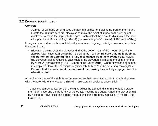
2.2 Zeroing (continued) Controls
Azimuth or windage zeroing uses the azimuth adjustment dial at the front of the mount. Rotate the azimuth zero dial clockwise to move the point of impact to the left; or anti-clockwise to move the impact to the right. Each click of the azimuth dial moves the point of impact by ½ Minute of Angle (MOA) (approximately ½” (12.7mm) at 100 yards (91m)).
Using a common item such as a flat-head screwdriver, dog tag, cartridge case or coin, rotate the azimuth dial.
Elevation zeroing uses the elevation dial at the bottom rear of the mount. Unlock the zeroing lock (silver tab) by raising it up as far as it will go. Be sure that the lock pin at the bottom of the zeroing lock is fully disengaged from the elevation dial. Adjust the elevation dial as required. Each click of the elevation dial moves the point of impact by ½ MOA (approximately ½” (12.7mm) at 100 yards (91m). When elevation adjustment is completed, lower the zeroing lock (silver tab) fully to lock the elevation zero in place. Be sure that the lock pin at the bottom of the zeroing lock is fully engaged into the elevation dial.
A mechanical zero of the sight is recommended so that the optical axis is in rough alignment with the bore axis of the weapon. This will make zeroing easier to accomplish.
To achieve a mechanical zero of the sight, adjust the azimuth dial until the gaps between the mount base and the front fork of the optical housing are equal. Adjust the elevation dial by raising the silver lock and turning the dial until the sight body is parallel to the rail. (See Figure 2-3).
15

OPM 009 REV A Copyright © 2011 Raytheon ELCAN Optical Technologies 16
2.2 Zeroing (continued)
In addition to setting the sight to its mechanical zero, it is also recommended that the weapon is bore sighted prior to going on the zeroing range. When done correctly, this can save a lot of time and ammunition. Follow the steps below to acquire a good bore sight.
1. Place the weapon on a stable platform that does not allow for any movement (bench rest, cradle, rucksack).
2. Get behind the weapon and along the barrel axis.
3. Choose an identifiable object down range (preferably at about the same range that you will be zeroing at).
4. If possible, look through the barrel and center the object in the bore circle. Otherwise, look parallel to the bore axis and align the weapon with an identifiable object.
5. Look through the optic and locate the identifiable object.
6. Adjust the windage and elevation until the crosshairs are on the object.
7. As necessary, perform safety checks, assemble weapon, follow range procedures and then commence zeroing (first shot should be on paper).

OPM 009 REV A Copyright © 2011 Raytheon ELCAN Optical Technologies
2.2 Zeroing (continued)
Figure 2-3: Azimuth/Windage Adjusts
17
EQUAL GAPS = MECHANICAL ZERO AZIMUTH/WINDAGE ADJUST
CW (POI LEFT)
CCW (POI RIGHT)
SIGHT BODY PARALLEL TO RAIL = MECHANICAL ZERO

OPM 009 REV A Copyright © 2011 Raytheon ELCAN Optical Technologies 18
2.2 Zeroing (continued)
The recommended distance for zeroing the SpecterOS 4x is at 100 meters! However, a 25 meter zero will enable fall of shot to be registered on a target. It is recommended that the marksman fires three to five round groups and make adjustments based upon the geometric center of those groups.
1. Look through the sight with proper eye relief and align the aiming point of the center dot onto the center of the target.
Aimed fire shot group
Sample Target Figure 2-4: Aimed fire shot group
2. Fire three to five aimed individual rounds (Figure 2-4).
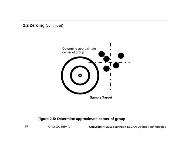
3. Determine the approximate center of the group (Figure 2-5).
OPM 009 REV A Copyright © 2011 Raytheon ELCAN Optical Technologies 19
Determine approximate center of group
Sample Target
Figure 2-5: Determine approximate center of group
2.2 Zeroing (continued)

OPM 009 REV A Copyright © 2011 Raytheon ELCAN Optical Technologies 20
2.2 Zeroing (continued)
4. Measure the amount of movement required left or right (Azimuth or windage) to move the center of the POI group onto the aimpoint in mm or inches (Figure 2-6).
5. To adjust azimuth/windage, each click of the azimuth/windage dial moves the POI by ½ MOA (approximately ½” (12.7mm) at 100 yards (91m)). Direction of POI change is labelled on the housing next to the Azimuth Adjustment Dial. Table 2.1 is provided to convert mm or inches into a ½ MOA click of movement for a given target range. Calculate the number of clicks to adjust the POI to the aimpoint for your target’s range.
Figure 2-6: Adjust azimuth/windage or elevation
ELEVATION
Sample Target
AZIMUTH/WINDAGE

OPM 009 REV A Copyright © 2011 Raytheon ELCAN Optical Technologies 21
2.3 Zeroing (continued)
Calculation for _______ Range to Target:
RIGHT LEFT
Aimpoint
Bullet Impact
Adjust CCW to move bullet RIGHT
Adjust CW to move bullet LEFT
L R
Figure 2-7: Adjust POI - Azimuth/Windage
Measured from ______ mm or inches = clicks to adjust
Conversion factor for that range

OPM 009 REV A Copyright © 2011 Raytheon ELCAN Optical Technologies 22
2.2 Zeroing (continued)
6. Measure the amount of movement required up or down (elevation) to move the center of the POI group onto the aimpoint in mm or inches (Figure 2-6).
7. Each click of the elevation dial moves the POI by ½ MOA (approximately ½” (12.7mm) at 100 yards (91m)). Table 2-1 is provided below to convert mm or inches into a ½ MOA click of adjustment for a given target range. Calculate the number of clicks to adjust the POI to the aimpoint for your target’s range.
To adjust elevation:
Push the elevation zero lock (silver tab) up to disengage.
When viewing the sight from the rear, rotate the elevation dial Right to Raise - UP the POI or Left to Lower - Down the POI. Direction of POI change is labelled on the sight.
Caution: To prevent damage, be sure that the lock is fully disengaged before attempting to turn the elevation dial!
When elevation adjustment is completed, lower the zero lock fully to lock the elevation zero in place. Be sure that the lock pin at the bottom of the zero lock is fully engaged into the elevation dial.
It is important to ensure that the zero lock is pushed back down to lock the elevation zero dial when zeroing is completed!

OPM 009 REV A Copyright © 2011 Raytheon ELCAN Optical Technologies 23
1. Lift tab to unlock elevation zero. 2. Rotate dial UP/DN to move bullet UP/DN. 3. Lower tab to lock elevation zero.
Figure 2-8: Adjust POI - Elevation
UP
Aimpoint
Bullet Impact
DOW
2.2 Zeroing (continued)
Calculation for _______ Range to Target:
Measured from ______ mm or inches = clicks to adjust
Conversion factor for that range

OPM 009 REV A Copyright © 2011 Raytheon ELCAN Optical Technologies 24
2.2 Zeroing (continued)
Table 2-1: POI Movement per click of Adjustment - Azimuth or Elevation
Range to Target
Meters Feet POI Movement in mm/click of adjustment
POI Movement in in/click of adjustment
25 82 4 0.10
50 164 7 0.30
100 328 15 0.60
200 656 29 1.10
300 984 44 1.70
400 1312 58 2.30
500 1640 73 2.90
600 1968 87 3.40
700 2297 102 4.00
800 2625 116 4.60
Conversion Factor
10 32.8 1.58 0.06
1000 3280 145 5.70
1500 4920 218 8.60
2000 6560 291 11.50

OPM 009 REV A Copyright © 2011 Raytheon ELCAN Optical Technologies 25
3.1 Reticle and Ranging The SpecterOS 4x reticle provides the shooter with easy-to-locate aiming marks to designate the target both at short and long ranges. The following are sample illustrations of a reticle pattern.
Figure 3-1 Sample Illustration of Reticle -- Calibrated for 5.56, M855 ball, M4 Weapon (not to scale)
Figure 3-2 Sample Illustration of Reticle detail (not to scale)
4
10
8
6
M4 100- 600 m
M249 700- 1000m
4X ON LY
4
10
8
6
CHAPTER 3: PRINCIPLES OF OPERATION

OPM 009 REV A Copyright © 2011 Raytheon ELCAN Optical Technologies
3.1 Reticle and Ranging (continued)
Describing the sample reticle, the main horizontal line provides a reference to the marksman and coincides with the 100 meter aiming point. The reticle pattern is designed to be zeroed at 100 meters.
A red dot aiming point is placed at the reticle crosshair center and is 1.5 MOA in size.
The ballistic drop reticle provides calibrated drop increments of 100 meters. The 400 and 600 meter stadia lines are labelled. At each range, the width of the stadia line represents a 19” wide target (the approximate width of a man’s chest).
The calibre of the weapon (5.56mm or 7.62mm) is indicated on the reticle as well as the sight.
3.2 Reticle Illumination The SpecterOS 4x provides illumination for two types of reticles (see Figure 2-8):
A red dot at the center of the crosshairs; and
A Range Estimating and Bullet Drop Compensation Reticle.
Each reticle has multiple brightness settings which can be set by the Reticle Illumination Switch (rotary) on the left side of the sight (see Figure 2-9):
Counter Clockwise rotation - illuminates the Red Dot with 5 intensity levels.
Clockwise rotation - illuminates the ballistic reticle with 5 intensity levels.
The first two settings from OFF, each way, are night vision equipment compatible.
26

OPM 009 REV A Copyright © 2011 Raytheon ELCAN Optical Technologies 27
Figure 3-3 Sample Illustration: Red Dot and Illuminated Ballistic Reticle
Figure 3-4: Reticle Illumination Switch Operation - rotate the switch to desired reticle brightness setting.
4
10
8
6
The SpecterOS 4x is designed to give the marksman maximum control of reticle illumination. However, at the higher illumination settings, reddish light shines forward from the sight. These higher illumination settings are for use in bright daylight.
Failure to use the lower reticle illumination settings at night, or failure to take other tactical measures to hide your forward light emissions during darkness, could reveal your position.
3.2 Reticle Illumination (continued)
5 RED DOT INTENSITY LEVELS 2 NIGHT VISION
5 STADIA LINE INTENSITY LEVELS 2 NIGHT VISION
WARNING

OPM 009 REV A Copyright © 2011 Raytheon ELCAN Optical Technologies
The SpecterOS 4x is designed for ruggedness and minimal maintenance. The following sections describe recommended maintenance procedures.
4.1 Preventative Maintenance
Prior to use in the field and every week of use, the following routine maintenance is recommended:
Inspect the sight for missing or damaged parts.
Inspect the sight for visual obstruction of target image, dust, dirt, pits or moisture on optical surfaces, loose or broken optical elements. If these conditions cannot be corrected by cleaning (see Section 3.2), the sight is unsuitable for use.
Check battery cap - Ensure that the cap is present. Inspect the threads on the battery housing and battery cap for damage, dirt or moisture. Ensure that the rubber washer is present, free of damage and seated properly. An absent or improperly seated battery cap could lead to a loss of power or shorten battery life.
Check the reticle - if the reticle does not illuminate, try replacing the battery.
Verify proper positioning and mounting of the sight (see Section 2.1).
CHAPTER 4: MAINTENANCE
28

OPM 009 REV A Copyright © 2011 Raytheon ELCAN Optical Technologies 29
4.2 Changing the Battery The battery cap is located on the Reticle Illumination Switch. To change the battery:
Grip the large diameter switch to prevent it from rotating while turning the small diameter section in a counter-clockwise direction.
Remove the old battery and dispose of it properly (see note below).
Place a new DL1/3N Lithium battery into the compartment with the “-” terminal facing in.
Replace battery cover (hand tighten only). See Figure 4-1.
Figure 4-1: Battery Replacement

OPM 009 REV A Copyright © 2011 Raytheon ELCAN Optical Technologies
4.3 Cleaning
Clean the surfaces of the optical sight lenses by using cotton lens paper, microfiber or freshly laundered cheesecloth saturated with alcohol to wipe in a circular motion. Dry the lens by wiping with a clean piece of the same material in the same circular motion from the center outward.
CAUTION
DO NOT use fingers to clean lenses. Apply only a light downward pressure on the cleaning material.
DO NOT immerse the SpecterOS 4x sight in solvents.
DO NOT use hot water to clean the sight.
If mud or hardened dirt is on or near the lens, flush with cold or warm water and gently wipe with a moistened tissue. Repeat the procedure above if necessary.
DO NOT use compressed air to clean sight.
30

OPM 009 REV A Copyright © 2011 Raytheon ELCAN Optical Technologies
Description Raytheon ELCAN Part Number
Battery cover without lanyard 903236-003 (Black)
903236-001 (Flat Dark Earth)
Battery cover with lanyard 903236-003 KIT (Black)
903236-001 KIT (Flat Dark Earth)
Lens Cover 207491-003 (Black)
207491-001 (Flat Dark Earth)
4.4 Replacement Parts
31
Table 4-1: Replacement Parts

OPM 009 REV A Copyright © 2011 Raytheon ELCAN Optical Technologies 32
4.5 Preparation for Shipment
Clean and dry the sight. It is highly recommended that the lens covers be installed to protect the optical elements during shipment.
1. For shipment while attached to the weapon, make safe and properly stow the weapon.
2. For shipment as an individual sight, reinsert the sight into its original packaging, or equivalent, to cushion against impact and prevent crushing.

OPM 009 REV A Copyright © 2011 Raytheon ELCAN Optical Technologies
This page intentionally left blank.

450 Leitz Road, Midland ON Canada L4R 5B8
Telephone: 011.705.526.5401 www.ELCANsightingsystems.com
Dated January 10, 2011
Copyright 2011, Raytheon ELCAN Optical Technologies. All rights reserved. Specifications are subject to change.