
SPECIFICATION FOR GLASS-FIBER-REINFORCED CONCRETE … · 246 Facing – A layer of mortar or...
23
1 2 3 4 SPECIFICATION FOR 5 GLASS-FIBER-REINFORCED CONCRETE PANELS 6 7 A PCI Standard 8 9 10 11 PCI 128-18 12 Copyright © 2018 13 Precast/Prestressed Concrete Institute 14 All rights reserved. This book or any part thereof may not 15 be reproduced in any form without the written permission 16 of the Precast/Prestressed Concrete Institute. 17 18 19 20 21 22 23 24 25 26 27 28 29 30 31 32 33 34 35 36 ISBN ??? 37 38 Printed in U.S.A. 39 40 41 42 43 Substantial effort has been made to ensure that all data and information in this specification are accurate. However, PCI cannot accept responsibility for any errors or oversights in the use of materials or in the preparation of engineering plans. This publication is intended for use by professional personnel competent to evaluate the significance and limitations of its contents and able to accept responsibility for the application of the material it contains. Special conditions on a project may require more specific evaluation and practical engineering judgement.
Transcript of SPECIFICATION FOR GLASS-FIBER-REINFORCED CONCRETE … · 246 Facing – A layer of mortar or...

1
2
3
4
SPECIFICATION FOR 5
GLASS-FIBER-REINFORCED CONCRETE PANELS 6
7 A PCI Standard 8
9 10 11
PCI 128-18 12 Copyright © 2018 13
Precast/Prestressed Concrete Institute 14 All rights reserved. This book or any part thereof may not 15 be reproduced in any form without the written permission 16 of the Precast/Prestressed Concrete Institute. 17 18 19 20 21 22 23 24 25 26 27 28 29 30 31 32 33 34 35 36
ISBN ??? 37 38
Printed in U.S.A. 39 40 41 42
43
Substantial effort has been made to ensure that all data and information in this specification are accurate. However, PCI cannot accept responsibility for any errors or oversights in the use of materials or in the preparation of engineering plans. This publication is intended for use by professional personnel competent to evaluate the significance and limitations of its contents and able to accept responsibility for the application of the material it contains. Special conditions on a project may require more specific evaluation and practical engineering judgement.
SPECIFICATION FOR GLASS-FIBER-REINFORCED CONCRETE PANELS 44 45
FOREWORD 46 47 This specification provides minimum requirements for the design, manufacture, and 48 installation of glass-fiber-reinforced concrete (GFRC) panels. The primary emphasis is on 49 thin-walled alkali-resistant (AR) GFRC architectural cladding panels with a steel-frame 50 support structure made by the spray-up process in controlled factory conditions. 51 52 This specification also includes minimum requirements for GFRC panels manufactured using 53 the premix process in controlled factory conditions. 54 55 The potential of using GFRC systems was recognized during the developmental work on 56 glass-fiber-reinforced plastics carried out in the 1940s. Early experience indicated that 57 portland cement composites made with unprotected E-glass fiber (conventional glass-fiber 58 reinforcement used in plastics) were subject to alkaline attack. Because of this fact, a special 59 AR glass-fiber product was developed. 60
61 Following the successful development of AR glass fibers in the late 1960s, test programs 62 were undertaken to determine the properties of portland cement and AR glass-fiber 63 composites. AR glass fibers have been used in GFRC panels in the United States since the 64 early 1970s. 65 66 The PCI GFRC Certification Committee developed this specification. The PCI GFRC 67 Certification Committee Task Group working on this document were: 68 69
TASK GROUP FOR PCI 128-18 70 Edward S. Knowles, PE, FPCI, Chair 71
72 Sidney Freedman, FACI, FCPCI, PCI Titan Edwin A. McDougle, PE, FPCI, PCI Titan John Jones, B.Eng., FACI W. Michael Paris, PE
James A. Lee Bradley G. Williams, PE Ray A. McCann, SE, FACI, FPCI
73 PREFACE 74
75 This standard was developed following the protocols required by the PCI Group Operations 76 Manual. The provisions were balloted in the PCI Glass Fiber Reinforced Concrete Panels 77 Committee. Review and comments by the PCI Technical Activities Council (TAC) followed 78 and resulted in substantive changes to the document. These changes were returned to TAC 79 and accepted. The document was then submitted to the PCI Standards Committee, where 80 additional review and balloting took place. The membership of that committee is balanced 81 according to the accreditation rules of the American National Standards Institute (ANSI). In 82 addition, a public review period was provided, and public comments were resolved through 83 the PCI Standards Committee. The entire process is a consensus process involving PCI 84 members, nonmembers of PCI, and the general public. 85 86 87

88 TABLE OF CONTENTS 89
90 1.0 General ............................................................................................................ 5 91 92 1.1 Scope ........................................................................................................ 5 93 94 1.2 Definitions .................................................................................................. 5 95 96 1.3 Notation ..................................................................................................... 7 97 98 1.4 Reference standards ................................................................................. 8 99 100 2.0 Materials ....................................................................................... …………….11 101 102 2.1 General………………………………………………………………………… 11 103 104 2.2 Facing and backing .................................................................................. 11 105
106 2.2.1 Cement ............................................................................................ 11 107 2.2.2 Facing materials .............................................................................. 11 108 2.2.3 Sand for backing .............................................................................. 11 109 2.2.4 Mixing water..................................................................................... 11 110 2.2.5 Admixtures and curing agents ......................................................... 11 111
112 2.3 Reinforcement ......................................................................................... 12 113
2.3.1 Alkali-resistant glass fiber ................................................................ 12 114 115 2.4 Panel frame and hardware ...................................................................... 12 116
2.4.1 Panel frame ..................................................................................... 12 117 2.4.2 Anchors and inserts ......................................................................... 12 118 2.4.3 Connection hardware ....................................................................... 13 119
120 2.5 Welding ................................................................................................... 13 121 122 2.6 Coatings .................................................................................................. 13 123 124 3.0 Design............................................................................................................. 14 125 126 3.1 General .................................................................................................... 14 127 128 3.2 Design loads ............................................................................................ 14 129 130 3.3 Skin design .............................................................................................. 14 131 132 3.4 Panel frame design .................................................................................. 15 133 134 3.5 Connection, anchor, and insert design .................................................... 16 135 136

137 3.6 Joints ....................................................................................................... 17 138 139 4.0 Manufacturing ................................................................................................ 18 140 141 4.1 GFRC panel manufacture ........................................................................ 18 142 143 4.2 Molds ....................................................................................................... 18 144 145 4.3 Proportioning ........................................................................................... 18 146 147 4.4 Mist coat .................................................................................................. 18 148 149 4.5 Placement of facing ................................................................................. 19 150 151 4.6 Spray-up of backing ................................................................................. 19 152 153 4.7 Panel frame ............................................................................................. 19 154 155 4.8 Curing ...................................................................................................... 19 156 4.8.1 Polymer admixture curing ................................................................ 19 157 4.8.2 Moist curing ..................................................................................... 19 158 159 5.0 Quality control ............................................................................................... 21 160 161 5.1 General .................................................................................................... 21 162 163 6.0 Installation ...................................................................................................... 22 164 165 6.1 General .................................................................................................... 22 166 167 6.2 Connections............................................................................................. 22 168 169 7.0 Premix GFRC ................................................................................................. 23 170 171 7.1 General………………………………………………………………………… 23 172 173 7.2 Design………..…………….……………………………………….…….………23 174 175 7.3 Manufacturing…………….……………………………………….…….………23 176 177 7.4 Quality control………………………………………………………………… 23 178
179 180 181 182 183 184 185
1.0 General 186 187 1.1 Scope 188 189
This specification provides minimum requirements for the design, manufacture, and 190 installation of glass-fiber-reinforced concrete (GFRC) panels, fabricated with or without panel 191 frames, using the spray-up process or the premix process. Energy considerations for the 192 design of enclosure systems are excluded from this scope. 193
194 1.2 Definitions 195 196 Admixture — A material other than water, aggregate, or hydraulic cement, used as an 197 ingredient of concrete and added to concrete before or during its mixing to modify its 198 properties. 199 200 Air permeability — The rate of air flow through a material; commonly expressed in perm-201 inches. 202 203 Alkali-resistant (AR) glass fiber — Fiber conforming to ASTM C1666. 204 205 Anchor, flex — Device connecting GFRC skin to panel frame to resist tensile or compressive 206 forces and detailed to allow in-plane movement with minimal restraint force development. 207 208 Anchor, gravity — Device to transfer GFRC skin weight to panel frame. 209 210 Anchor, seismic — Device connecting GFRC skin to panel frame to resist in-plane seismic 211 forces. 212 213 Backing — The GFRC deposited into the mold after the face mixture or veneer has been 214 placed and consolidated. 215 216 Bond breaker — With specific reference to GFRC, a substance placed to prevent bonding 217 between a face material such as natural stone and the GFRC backing. 218 219 Bonding agent — With specific reference to GFRC, a substance used to increase the bond 220 between hardened GFRC and a subsequent application of GFRC, such as a patch. 221 222 Bonding pad — A thickened area of GFRC that covers the foot of a flex, gravity, or seismic 223 anchor. 224 225 Boss — With specific reference to GFRC, a thickened area of backing into which an insert 226 can be embedded. 227 228 Chopped glass — Noncontinuous multifilament glass-fiber strands. 229 230 Compaction — With specific reference to GFRC, the process of reducing the volume of 231 voids in the face mixture and GFRC backing by vibrating, tamping, rolling, or some 232 combination of these. 233 234

Connection — Assembly including anchors, inserts, kerfs, and/or hardware for the 235 attachment of GFRC panels, with or without a frame, to each other or to the building 236 structure. 237 238 Creep — The time-dependent increase in deformation caused by a sustained load. 239 240 Curing — Action taken to maintain moisture and temperature conditions in a freshly placed 241 cementitious mixture to allow hydraulic cement hydration and (if applicable) pozzolanic 242 reactions to occur so that the properties of the mixture may develop. 243
Dunnage — Materials used for temporary support during storage and transportation. 244 245 Facing – A layer of mortar or concrete greater than 1/8 in. (3 mm) nominal thickness at the 246 exposed face of GFRC. 247 248 Fiber — An individual alkali-resistant glass filament with a length-to-diameter ratio of at least 249 20:1. 250 251 Fiber content — The ratio, usually expressed as a percentage, of glass fiber to total 252 composite; can be by weight or by volume. 253 254 General building code – governing building code adopted by jurisdiction local to project. 255 256 Insert — A connecting device or handling device cast into a GFRC panel. 257 258 Kerf — A slot sawn or cast into GFRC to receive connection hardware. 259 260 Mist coat — A thin (1/8 in. [3 mm] nominal) coat of cement/sand slurry of a composition 261 similar to the GFRC backing mixture, but without glass fiber. It may be the exposed face of a 262 GFRC panel. 263 264 Mold — The container or surface against which fresh GFRC is deposited to give it a desired 265 shape. 266 267 Overspray GFRC — GFRC material that is sprayed outside the confines of the mold. 268 269 Panel — The entire prefabricated GFRC unit. 270 271 Panel frame — Plant-attached steel frame used to support and stiffen the skin and provide a 272 means for connecting to the building frame. 273 274 Polymer admixture — An emulsion of an alkali-resistant synthetic thermoplastic in water 275 obtained by polymerization and used as a curing admixture. 276 277 Premix — A process of mixing cement, sand, prechopped AR glass fiber, admixtures, and 278 water into a mortar for subsequent placement by spraying, casting with vibration, press-279 molding, extruding, or slipforming. 280 281 Rib — (1) A stiffening member backing the skin. (2) A projection from the panel face. 282

283 Sealant — Compressible material used to exclude water and solid foreign materials from 284 joints. 285 286 Sealer — Clear chemical compound applied to the surface for the purpose of reducing water 287 absorption or improving weathering qualities. 288 289 Sizing — Coating materials applied to the glass fibers during manufacture to facilitate and/or 290 improve the processing and performance of the fiber. 291 292 Skin — The thin exterior section of a panel, including the face mixture/veneer finish and 293 GFRC backing, but excluding ribs, bosses, panel frame, etc. 294 295 Slurry — A mixture of water, portland cement, sand, and other additions or admixtures in 296 suspension. 297 298 Spray-up process — The simultaneous chopping and spraying of glass fibers and spraying 299 of slurry onto a mold, followed by appropriate compaction. 300 301 Strand — A number of individual continuous fibers bound together by sizing. Typical alkali-302 resistant glass-fiber strands contain 102, 204, or 408 fibers. 303 304 Tolerance — Specified permissible variation from stated requirements, such as dimensions 305 and strength. 306 307 Volume change — An increase or decrease in volume of the skin. It includes initial drying 308 shrinkage, moisture-induced movement, thermal movement, and creep. 309 310 1.3 Notation 311
312 f'n = nominal value of maximum stress, not adjusted by shape factors, allowed in design 313
fnm = nominal value of maximum flexural stress, adjusted by shape factors, allowed in design 314
fnn = nominal value of maximum direct tensile stress allowed in design 315
fnv = nominal value of maximum shear stress allowed in design 316
fur = average 28-day test values of flexural ultimate stress 317
fyr = average 28-day test values of flexural yield stress 318
S'n = 28-day anchor or bonding pad test strength in tension or shear 319
Sn = nominal anchor design strength 320
s = shape factor, to account for stress redistribution in different cross sections: 321
Single skin: s = 1.0 322
Box section: s = 0.5 323
t = Student’s t, a 99%, one sided distribution statistical value to account for data scatter 324

φ = strength reduction factor 325
σc = standard deviation of anchor, insert, or kerf test values 326
σu = standard deviation of 28-day test values of flexural ultimate stress 327
σy = standard deviation of 28-day test values of flexural yield stress 328
329
1.4 Reference standards and other referenced documents 330
Referenced documents identified by am asterisk (*) are not consensus standards; rather they 331
are documents developed within the precast/prestressed concrete industry that represent 332
acceptable procedures for design and construction to the extent referred to in the specified 333
section. 334
ASTM International 335 336
A29/A29M-16 Standard Specification for General Requirements for Steel
Bars, Carbon and Alloy, Hot-Wrought
A36/A36M-14 Standard Specification for Carbon Structural Steel
A108-13 Standard Specification for Steel Bar, Carbon and Alloy, Cold-
Finished
A153/A153M-16a Standard Specification for Zinc Coating (Hot-Dip) on Iron and
Steel Hardware
A500/A500M-18 Standard Specification for Cold-Formed Welded and
Seamless Carbon Steel Structural Tubing in Rounds and
Shapes
A513/A513M-15 Standard Specification for Electric-Resistance-Welded
Carbon and Alloy Steel Mechanical Tubing
A572/A572M-18 Standard Specification for High-Strength Low-Alloy
Columbium-Vanadium Structural Steel
A653/A653M-17 Standard Specification for Steel Sheet, Zinc-Coated
(Galvanized) or Zinc-Iron Alloy-Coated (Galvannealed) by the
Hot-Dip Process
A924/A924M-17a Standard Specification for General Requirements for Steel
Sheet, Metallic-Coated by the Hot-Dip Process
A1003/A1003M-15 Standard Specification for Steel Sheet, Carbon, Metallic- and
Nonmetallic-Coated for Cold-Formed Framing Members
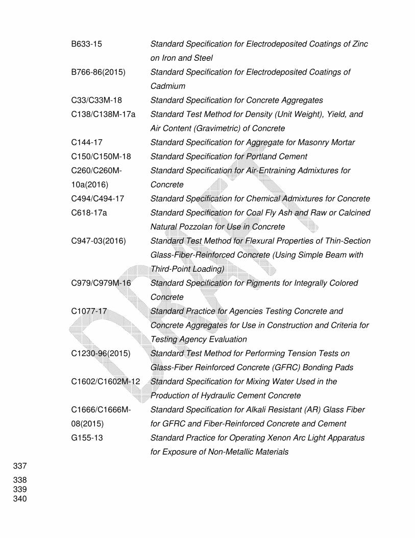
B633-15 Standard Specification for Electrodeposited Coatings of Zinc
on Iron and Steel
B766-86(2015) Standard Specification for Electrodeposited Coatings of
Cadmium
C33/C33M-18 Standard Specification for Concrete Aggregates
C138/C138M-17a Standard Test Method for Density (Unit Weight), Yield, and
Air Content (Gravimetric) of Concrete
C144-17 Standard Specification for Aggregate for Masonry Mortar
C150/C150M-18 Standard Specification for Portland Cement
C260/C260M-
10a(2016)
Standard Specification for Air-Entraining Admixtures for
Concrete
C494/C494-17 Standard Specification for Chemical Admixtures for Concrete
C618-17a Standard Specification for Coal Fly Ash and Raw or Calcined
Natural Pozzolan for Use in Concrete
C947-03(2016) Standard Test Method for Flexural Properties of Thin-Section
Glass-Fiber-Reinforced Concrete (Using Simple Beam with
Third-Point Loading)
C979/C979M-16 Standard Specification for Pigments for Integrally Colored
Concrete
C1077-17 Standard Practice for Agencies Testing Concrete and
Concrete Aggregates for Use in Construction and Criteria for
Testing Agency Evaluation
C1230-96(2015) Standard Test Method for Performing Tension Tests on
Glass-Fiber Reinforced Concrete (GFRC) Bonding Pads
C1602/C1602M-12 Standard Specification for Mixing Water Used in the
Production of Hydraulic Cement Concrete
C1666/C1666M-
08(2015)
Standard Specification for Alkali Resistant (AR) Glass Fiber
for GFRC and Fiber-Reinforced Concrete and Cement
G155-13 Standard Practice for Operating Xenon Arc Light Apparatus
for Exposure of Non-Metallic Materials
337
338 339 340

American Welding Society 341 342
D1.1/D1.1M:2015 Structural Welding Code – Steel
D1.3/D1.3M:2018 Structural Welding Code – Sheet Steel
D1.4/D1.4M:2011 Structural Welding Code – Reinforcing Steel
343
American Iron and Steel Institute 344 345
S100-16 North American Specification for the Design of Cold-Formed
Steel Structural Members
S240-15 North American Standard for Cold-Formed Steel Structural
Framing
346
American Institute of Steel Construction 347 348
ANSI/AISC 360-16 Specification for Structural Steel Buildings
349 International Accreditation Service, Inc 350 351
*AC 157 Accreditation Criteria for Fabricator Inpsection Programs for
Reinforced and Precast/Prestressed Concrete
352 353 Precast/Prestressed Concrete Institute 354 355
*MNL 130-09 Manual for Quality Control for Plants and Production of Glass
Fiber Reinforced Concrete Products Cited in: Sections 3.5.3;
4.1.1; 5.1.1; 5.1.2 and 7.4.1
*MNL 135-00 Tolerance Manual for Precast and Prestressed Concrete
Construction Cited in: Sections 4.1.3 and 6.1.4
356

2.0 Materials 357
358 2.1 General 359 360
2.1.1 Materials shall conform to the requirements of this chapter. Materials not included 361 in this specification are permitted only with approval of the engineer and architect 362 of record and when acceptable evidence of satisfactory short- and long-term 363 performance is provided. 364
365 2.2 Facing and backing 366 367
2.2.1 Cement 368 2.2.1.1 Portland cements shall conform to ASTM C150. 369
370 2.2.2 Facing materials 371
2.2.2.1 Compatibility of facing and backing shall be considered when developing 372 mixture proportions. 373
374 2.2.2.2 Where fine and coarse aggregates are used for exposed finishes, they 375
shall be clean, hard, strong, durable, inert, and free of staining or 376 deleterious material. 377
378 2.2.2.3 Aggregates shall conform to ASTM C33, except for gradation. 379 380
2.2.2.4 Aggregates shall be nonreactive with cement. 381 382
2.2.2.5 A bond breaker with flexible mechanical anchors shall be used with 383 natural stone veneer. 384
385 2.2.3 Sand for backing 386 387
2.2.3.1 Sands shall be washed and dried silica sand, be free of contaminants 388 and lumps, and shall conform to ASTM C144, except for gradation. 389
390 2.2.4 Mixing water 391 392
2.2.4.1 Mixing water shall be free from deleterious matter that may interfere with 393 the color, setting, or strength of the facing and backing and shall conform 394 to ASTM C1602. 395
396 2.2.5 Admixtures and curing agents 397 398
2.2.5.1 Admixtures shall conform to ASTM C494, Types A through G. Chloride 399 ion content shall be limited to 0.10% by weight of admixture. 400
401 2.2.5.2 Fly ash or other pozzolans used as supplemental cementitious materials 402
shall conform to ASTM C618. 403 404
2.2.5.3 Air-entraining admixtures shall conform to ASTM C260. 405
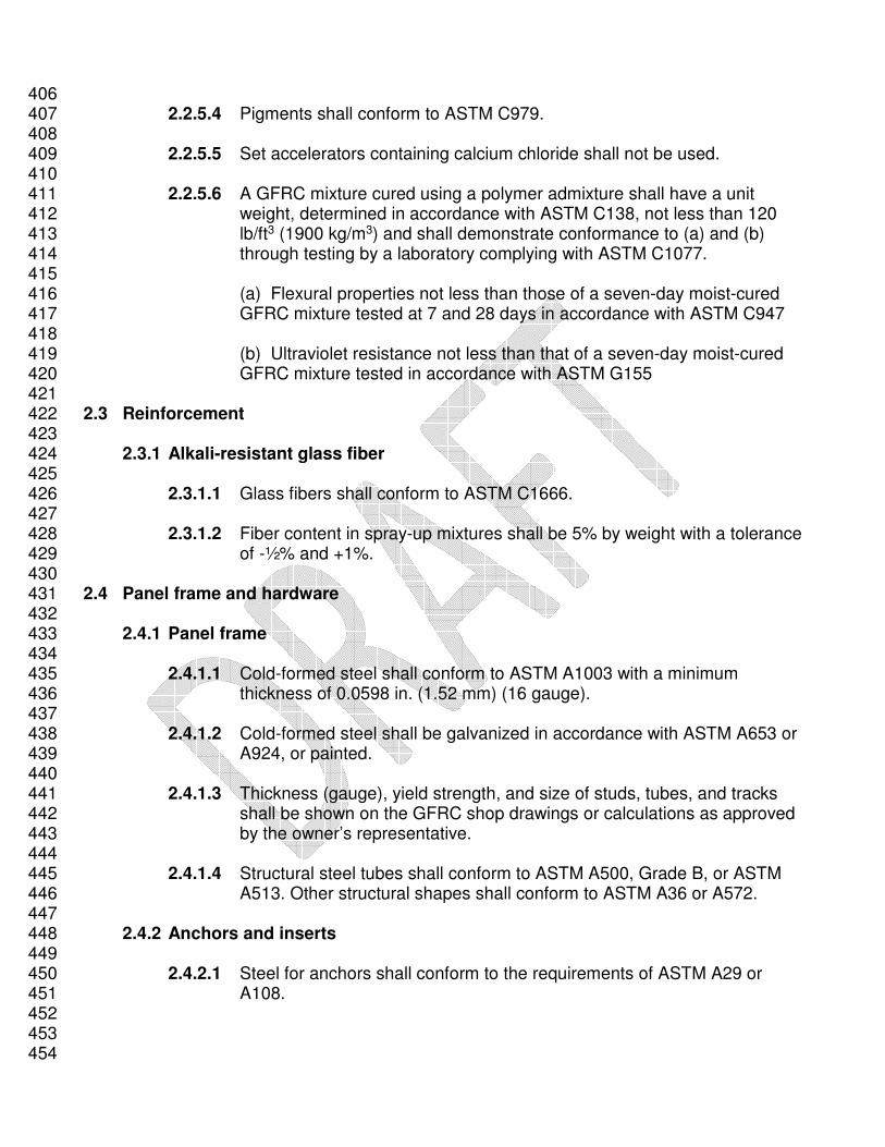
406 2.2.5.4 Pigments shall conform to ASTM C979. 407
408 2.2.5.5 Set accelerators containing calcium chloride shall not be used. 409
410 2.2.5.6 A GFRC mixture cured using a polymer admixture shall have a unit 411
weight, determined in accordance with ASTM C138, not less than 120 412 lb/ft3 (1900 kg/m3) and shall demonstrate conformance to (a) and (b) 413 through testing by a laboratory complying with ASTM C1077. 414
415 (a) Flexural properties not less than those of a seven-day moist-cured 416
GFRC mixture tested at 7 and 28 days in accordance with ASTM C947 417 418
(b) Ultraviolet resistance not less than that of a seven-day moist-cured 419 GFRC mixture tested in accordance with ASTM G155 420
421 2.3 Reinforcement 422 423
2.3.1 Alkali-resistant glass fiber 424 425
2.3.1.1 Glass fibers shall conform to ASTM C1666. 426 427 2.3.1.2 Fiber content in spray-up mixtures shall be 5% by weight with a tolerance 428
of -½% and +1%. 429 430 2.4 Panel frame and hardware 431 432
2.4.1 Panel frame 433 434
2.4.1.1 Cold-formed steel shall conform to ASTM A1003 with a minimum 435 thickness of 0.0598 in. (1.52 mm) (16 gauge). 436
437 2.4.1.2 Cold-formed steel shall be galvanized in accordance with ASTM A653 or 438
A924, or painted. 439 440
2.4.1.3 Thickness (gauge), yield strength, and size of studs, tubes, and tracks 441 shall be shown on the GFRC shop drawings or calculations as approved 442 by the owner’s representative. 443
444 2.4.1.4 Structural steel tubes shall conform to ASTM A500, Grade B, or ASTM 445
A513. Other structural shapes shall conform to ASTM A36 or A572. 446 447
2.4.2 Anchors and inserts 448 449
2.4.2.1 Steel for anchors shall conform to the requirements of ASTM A29 or 450 A108. 451
452 453 454

2.4.2.2 Anchors shall be corrosion-resistant using (a), (b), or (c). 455 456
(a) Hot-dip zinc coating in accordance with ASTM A153 457 458 (b) Electrodeposited cadmium coating in accordance with ASTM B766 459 460 (c) Electrodeposited zinc coating in accordance with ASTM B633 461 462 2.4.2.3 Inserts shall be isolated from dissimilar metals or metal coatings. 463
464 2.4.3 Connection hardware 465 466
2.4.3.1 Miscellaneous structural shapes shall be fabricated from steel 467 conforming to ASTM A36. Structural steel tubes shall conform to ASTM 468 A500, Grade B, or ASTM A513. 469
470 2.4.3.2 Cold-formed steel shall conform to ASTM A1003. 471 472 2.4.3.3 Cold-formed steel shall be galvanized in accordance with ASTM A653 or 473
A924, or painted. 474 475 2.5 Welding 476
477 2.5.1 Welding electrodes shall conform to the requirements of AWS D1.1, D1.3, and 478
D1.4, as applicable. 479 480
2.5.2 Welding electrodes shall match the base metal, except if electrodes with lower 481 strength than matching electrodes are allowed by design. 482
483 2.6 Coatings 484 485
2.6.1 Coatings, if specified by the owner’s representative, shall be water-vapor 486 permeable, and bulk-water impermeable. 487
488 2.6.2 Coatings shall be applied in accordance with coating manufacturer’s instructions. 489 490
491

3.0 Design 492 493
3.1 General 494 495
3.1.1 Design loads shall be resisted only by the GFRC backing. 496 497 3.1.2 Mist coats, facings, or veneers shall not be considered in strength determination 498
and shall not be included in test specimens. 499 500 3.1.3 The skin and panel frame shall not be designed as a composite system. 501
502 3.1.4 Determination of properties used in design shall be based on tests for each 503
mixture used. 504 505
3.1.4.1 Any departure from established materials and proportions shall require a 506 new series of tests. 507
508 3.2 Design loads 509 510
3.2.1 Loads specified by the general building code shall be considered as minimum 511 requirements. 512
513 3.2.2 Design loads shall include the following: 514 515
3.2.2.1 Gravity load including self-weight of panels. 516 517
3.2.2.2 Wind load. 518 519
3.2.2.3 Earthquake forces. 520 521
3.2.2.4 Restrained volume-change effects induced by thermal and moisture 522 changes and initial drying shrinkage. 523
524 3.2.2.4.1 Skins with facing and backing shall be tested and evaluated for 525
different volume-change properties of the facing and backing. 526 527
3.2.3 Load combinations shall be as prescribed by the general building code. 528 529 3.2.4 Skin, panel frame, and lifting device design shall include consideration of loads 530
imposed during handling, shipping, and installation. 531 532 3.3 Skin design 533 534
3.3.1 The nominal GFRC backing thickness shall be a minimum of ½ in. (13 mm). 535 536
3.3.2 Panels subject to out-of-plane bending shall be analyzed as a continuous one-way 537 beam or as a two-way system, as appropriate, based on the spacing and pattern 538 of flex anchors. 539
540

3.3.3 Average flexural yield and flexural ultimate strength test values shall be based on 541 a minimum of 20 sets of tests. Each set shall consist of six specimens, half of 542 which shall be tested with the mold side in tension and half of which shall be 543 tested with the mold side in compression. All tests shall be conducted in 544 accordance with ASTM C947. 545
546 3.3.4 Flexural stress due to factored loads shall not exceed: 547
φfnm = φ s f'n (Eq. 3-1) 548
where 549
φ = 0.75 550 f'n is the least of (a), (b), and (c): 551
(a) fyr (1 – tσy/fyr) (Eq. 3-2) 552
(b) 0.4fur (1 – tσu/fur) (Eq. 3-3) 553
(c) 1000 psi (6895 kPa) 554 where 555
t = 2.5 for the minimum number of 20 tests of six specimens each, as 556
specified in 3.3.3. If the number of tests is greater than specified in 3.3.3, 557
t shall be permitted to be determined using a 99% one-sided t-distribution 558
of the test results. 559
560
3.3.5 Tensile stress and shear stress due to factored load or differential volume-change 561 properties shall not exceed: 562
φfnn = φfnv = 0.4φ f'n (Eq. 3-4) 563
where 564
φ = 0.75 565 566
3.3.6 Calculation of skin stresses due to anchor restraint shall be based on the expected 567 yield strength of the anchor steel and shall not be less than 1.5 times the specified yield 568 strength. 569
570 3.3.6.1 A load combination including wind, volume change due to differential 571
properties of facing and backing, and volume-change restraint due to anchor 572 stiffness shall be included with a load factor of 1.0 on wind and a load factor of 1.2 573 on volume-change effects. 574
575 576 3.4 Panel frame design 577 578
3.4.1 Cold-formed steel frames shall be designed in accordance with AISI S100 and 579 S240. 580
581 3.4.1.1 Local effects at anchors and connections shall be accommodated in the 582
design of cold-formed frame members. 583 584 3.4.1.2 Weak axis strength and stiffness shall be provided for the transfer of in-585
plane seismic forces. 586

587 588 589 3.4.2 Structural steel shapes in panel frames shall be designed in accordance with 590
ANSI/AISC 360. 591 592 3.4.3 Panel frames shall be designed to transmit forces from skin anchors to building 593
connections with sufficient stiffness to prevent distress in the skin. 594 595 3.5 Connection, anchor, and insert design 596 597 3.5.1 Anchors and inserts embedded in GFRC and kerfs cast or cut into GFRC shall be 598
tested to determine tensile and/or shear strength. 599 600 3.5.2 A minimum of 20 specimens shall be tested for each type of anchor, insert, or kerf. 601 602 3.5.3 Anchor and bonding pad tests shall be performed in accordance with PCI MNL-603
130. 604 605 3.5.4 Factored load on anchors, inserts, and kerfs shall not exceed: 606 607
φSn = φ S'n (1 – t σc / S'n) (Eq. 3-5) 608
609 where 610
φ = 0.65 611 t = 2.5 for the minimum number of 20 tests, as specified in 3.5.2. If the number of 612 tests is greater than specified in 3.5.2, t shall be permitted to be determined using 613 a 99% one-sided t-distribution of the test results. 614
615 3.5.5 Arrangement of anchors from the skin to the panel frame shall minimize restraint 616
of the in-plane volume-change movements of the skin considering the direction of 617 stiffness and the direction of flexing of all anchors. 618
619 3.5.6 Flex anchors shall be of sufficient stiffness and strength to resist design loads 620
without lateral buckling. 621 622
3.5.7 Gravity anchors shall be of sufficient stiffness and strength to support the weight 623 of the skin without lateral buckling. 624
625 3.5.8 Seismic anchors shall be of sufficient stiffness and strength to resist in-plane 626
seismic forces without lateral buckling. 627 628
3.5.9 Inserts shall be embedded in GFRC bosses or bonding pads. 629 630 3.5.10 Arrangement of inserts shall minimize restraint of the in-plane volume-change 631
movements. 632 633
3.5.11 Overspray GFRC shall not be used to encapsulate inserts. 634 635
3.5.12 Miscellaneous structural shapes used as hardware in connections shall be 636 designed in accordance with ANSI/AISC 360. 637
638 3.5.13 Cold-formed steel used as hardware in connections shall be designed in 639 accordance with AISI S240. 640
641 3.6 Joints 642 643
3.6.1 Joint width and depth shall be determined based on the joint sealant considering 644 panel size, tolerances, anticipated in-plane movements, and story drift. 645
646
4.0 Manufacturing 647 648
4.1 GFRC panel manufacture 649 650
4.1.1 Manufacturing, facilities, and quality control procedures shall comply with PCI 651 MNL 130. 652
653 4.1.2 The GFRC manufacturing plant shall be certified at the time of bidding, production, 654
and installation in product group G by the PCI Plant Certification Program or in 655 accordance with AC157 by the IAS Fabricator Inspection Accreditation Program. 656
657 4.1.3 Panels shall be fabricated within tolerances specified in PCI MNL 135. 658
659 4.2 Molds 660 661
4.2.1 Molds shall conform to the profiles and dimensions given in the approved shop 662 drawings. 663
664 4.3 Proportioning 665 666
4.3.1 Backing and facing mixtures shall be proportioned to establish properties 667 used for design in accordance with (a) or (b). 668 669 (a) Trial mixtures 670 (b) Field experience 671 672
4.3.2 The backing mixture shall be proportioned considering (a) through (f). 673 674
(a) Fiber content 675 (b) Fiber length 676 (c) Cementitious materials–sand ratio 677 (d) Water–cementitious materials ratio 678 (e) Polymer curing admixture content (if used) 679 (f) Other admixture content 680 681
4.3. 3 Facing mixture shall be proportioned to achieve (a) through (h). 682 683
(a) Volume-change compatibility with GFRC backing mixture 684 (b) Required compressive strength 685 (c) Maximum water absorption 686 (d) Required entrained air content 687 (e) Maximum aggregate size 688 (f) Required cementitious materials–sand ratio 689 (g) Required water–cementitious materials ratio 690 (h) Required color and appearance 691
692 693 694 695

4.4 Mist coat 696 697
4.4.1 A mist coat, if used, shall be thick enough to cover mold surfaces and details and 698 provide cover for the glass fibers in the GFRC backing. 699
700 4.5 Placement of facing 701 702
4.5.1 Facing mixtures shall be placed and compacted to the required thickness. 703 704 4.6 Spray-up of backing 705 706
4.6.1 The backing shall be placed before drying or initial set of the mist coat or face 707 mixture. 708
709 4.6.2 The placement shall be by simultaneous depositing of glass fibers and slurry by 710
spraying onto a mold followed by compaction. 711 712
4.6.3 The thickness shall be equal to or greater than ½ in. (13 mm) or the design 713 thickness, whichever is greater. 714
715 4.7 Panel frame 716
717 4.7.1 Welding of panel frame members shall be in accordance AWS D1.1 for structural 718
steel and AWS D1.3 for sheet steel. 719 720 4.7.2 The panel frame shall be set into place before the backing reaches initial set. 721 722
4.7.3 Anchors shall be connected to the skin using bonding pads. 723 724
4.7.4 The panel frame and the flex anchors shall not protrude into the thickness of the 725 backing. 726
727 4.7.5 A bonding pad shall be placed over each anchor foot and made integral with the 728
fresh backing. 729 730
4.7.6 Bonding pad installation procedures shall be the same as those used in tests to 731 determine bonding pad design values. 732
733 4.8 Curing 734
735 4.8.1 Polymer admixture curing 736 737
4.8.1.1 GFRC backing temperature shall be maintained between 60 (16℃) and 738 120°F (50°C) for 12 to 16 hours. 739
740 4.8.2 Moist curing 741 742
4.8.2.1 As soon as practicable after panel frame installation or the completion 743 of spray-up operations in the absence of a panel frame, the panel shall 744

be covered and cured for 12 to 16 hours. During this time the 745 temperature of the GFRC shall be maintained between 50°F (10°C) 746 and 158°F (70°C). 747
748 4.8.2.2 After curing in accordance with 4.8.2.1, the panel shall be removed 749
from the mold and placed in a controlled curing environment at a 750 temperature above 50°F (10°C) and a minimum of 95% relative 751 humidity for a period of seven days. 752
753

5.0 Quality control 754 755
5.1 General 756 757
5.1.1 Each GFRC manufacturer shall implement a quality control program that 758 conforms to PCI MNL 130. 759
760 5.1.2 The quality control program shall include inspections and tests in 761
accordance with the requirements of PCI MNL 130. 762 763
5.1.3 Each GFRC panel shall be identified with a piece mark that can be 764 traced to the production drawings, erection drawings, testing records, and date 765 produced. 766
767 5.1.4 A system of records as evidence of proper manufacture and 768
conformance with plant standards and project specifications shall be maintained. 769 770

6.0 Installation 771 772
6.1 General 773 774
6.1.1 Installation shall be in accordance with the erection drawings. 775 776
6.1.2 Field modifications to the panel frame system shall be made only with the 777 approval of the panel manufacturer and the engineer responsible for the design. 778
779 6.1.3 Field checks shall be performed to verify that installation is in accordance with 780
the erection drawings. 781 782 6.1.4 Panels shall be installed within tolerances specified in PCI MNL 135. 783
784 6.2 Connections 785 786
6.2.1 Temporary connections shall not transfer unintended loads to panels already 787 installed. 788
789 6.2.2 Welding of connections shall be in accordance AWS D1.1 for structural steel 790
and AWS D1.3 for sheet steel. 791 792
6.2.3 Welding shall be performed in accordance with the erection drawings and 793 performed by welders certified in accordance with AWS D1.1 or AWS D1.3. 794
795 6.2.4 Galvanized components shall be touched up after cutting or welding with a rust-796
inhibitive or zinc-rich paint. 797 798
6.2.5 Field modifications shall be made only with the approval of the panel 799 manufacturer and the engineer responsible for the design. 800
801

7.0 Premix GFRC 802 803 7.1 General 804 805
7.1.1 Chapters 1 through 6 shall apply to premix GFRC unless modified by this 806 chapter. 807
808 7.1.2 Premix GFRC products shall contain 3% alkali-resistant glass fiber by weight of 809
the total mixture with a tolerance of ±½%. 810 811 7.2 Design 812 813
7.2.1 Flexural stress due to factored loads shall not exceed: 814
φfnm = φ s f'n (Eq. 7-1) 815
where 816
φ = 0.75 817 f'n is the least of (a), (b), and (c): 818
(a) fyr (1 – tσy/fyr) (Eq. 7-2) 819
(b) 0.4fur (1 – tσu/fur) (Eq. 7-3) 820
(c) 600 psi (4140 kPa) 821 where 822 t = 2.5 for the minimum number of 20 tests of six specimens each, as 823
specified in 3.3.3. If the number of tests is greater than specified in 3.3.3, 824
t shall be permitted to be determined using a 99% one-sided t-distribution 825
of the test results. 826
827 7.3 Manufacturing 828 829
7.3.1 Mixing equipment shall be appropriate for premix GFRC. 830 831
7.3.2 The mixture shall be designed to avoid separation of the mixture components 832 during delivery and placement. 833
834 7.3.3 Placing and casting procedures shall maintain a random glass fiber orientation in 835
the premix. 836 837 7.3.4 If premix is sprayed onto the mold, the material shall be placed and compacted 838
in layers not exceeding ¼ in. (6 mm). 839 840 7.4 Quality control 841 842
7.4.1 Premix glass content shall be verified by washout tests in conformance with PCI 843 MNL 130. 844