SPARK VENT GAS WATER IN AND WARNING - Streamline … Gas Water Heater... · INSTALLATION AND...
9
INSTALLATION AND SERVICE MANUAL NUMBER 6500016 ocroBER 1983 DIRECT SPARK IGNITION - DIRECT VENT GAS WATER H EATER FOR INSTALLATION IN RECREATIONAL VEHICLES AND MOBILE HOUSING FOR YOUR SAFETY, IF YOU SMELL GAS. 1. OPEN WINDOWS. 2, DON'T TOUCH ELECTRICAL SWITCHES. 3. EXTINGU]SH ANY OPEN FLAM ES. 4, IMMEDIATELY SHUT OFF GAS SUPPLY TO HEATER. WARNING DRAIN HEATER IF SUBJECT TO FREEZING TEMPERATURE. DO NOT STORE OR USE GASOLINE, OR OTHER COMBUSTIBLE MATERIALS OR LIQUIDS NEAR OR ADJACENT TO THIS HEATER OR ANY OTHER APPLIANCE. THIS APPLIANCE SHALL NOT BE INSTALLED IN ANY LOCATION WHERE FLAMMABLE LIQUIDS OR VAPORS ARE LIKELY TO BE PRESENT. INSTALLER: AFFIX THESE INSTRUCTIONS TO OR ADJACENT TO WATER HEATER. OWNER: RETAIN THESE INSTRUCTIONS AND WARRANTY FOR FUTURE REFERENCE. R*reation Vehicle lndustry Assciation oVr'M tytoR-FLoAmrnrca Water Heaters rfioR.FLO' TNDU5TRTES, TNE. AIYIERIEAN APPL'ANCE Iu'IG.CARP. 18450 SOUTH MILES ROAD CLEVELAND, OHIO 44128 (216) 663-7300 . TELEX: 985-496 2341 MICHIGAN AVENUE SANTA MONICA, CA. 90404 Q13l 829-1755 . TELEX: 652-422 Ur "A). SE TSIETET w/ /rPPROV€O
Transcript of SPARK VENT GAS WATER IN AND WARNING - Streamline … Gas Water Heater... · INSTALLATION AND...

INSTALLATION AND SERVICE MANUALNUMBER 6500016
ocroBER 1983
DIRECT SPARK IGNITION - DIRECT VENTGAS WATER H EATER
FOR INSTALLATION IN RECREATIONALVEHICLES AND MOBILE HOUSING
FOR YOUR SAFETY, IF YOU SMELL GAS.1. OPEN WINDOWS.2, DON'T TOUCH ELECTRICAL SWITCHES.3. EXTINGU]SH ANY OPEN FLAM ES.4, IMMEDIATELY SHUT OFF GAS SUPPLY TO HEATER.
WARNINGDRAIN HEATER IF SUBJECT TO FREEZING TEMPERATURE. DONOT STORE OR USE GASOLINE, OR OTHER COMBUSTIBLEMATERIALS OR LIQUIDS NEAR OR ADJACENT TO THIS HEATEROR ANY OTHER APPLIANCE. THIS APPLIANCE SHALL NOT BEINSTALLED IN ANY LOCATION WHERE FLAMMABLE LIQUIDSOR VAPORS ARE LIKELY TO BE PRESENT.
INSTALLER: AFFIX THESE INSTRUCTIONS TOOR ADJACENT TO WATER HEATER.
OWNER: RETAIN THESE INSTRUCTIONS ANDWARRANTY FOR FUTURE REFERENCE.
R*reation Vehicle lndustry Assciation
oVr'MtytoR-FLoAmrnrcaWater Heaters
rfioR.FLO'TNDU5TRTES, TNE.
AIYIERIEANAPPL'ANCE Iu'IG.CARP.
18450 SOUTH MILES ROADCLEVELAND, OHIO 44128(216) 663-7300 . TELEX: 985-496
2341 MICHIGAN AVENUESANTA MONICA, CA. 90404Q13l 829-1755 . TELEX: 652-422
Ur "A).SE TSIETETw/
/rPPROV€O
Tom
Sticky Note
MOR-FLO Gas Water Heater Installation and Service Manual provided courtesy of Jim Dupree - Houston, Texas
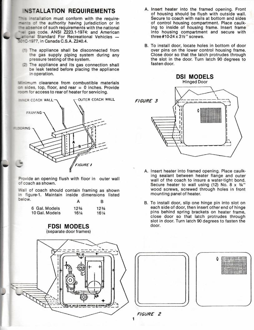
t{ STAL LATION REQUI REMENTS*' : -::: aiion must conform with the require-- * -- : :' :ne authority having jurisdiction or in"'.* i.:::-:e of such requirements with the national" .* ;:s ccde. ANSI 2223.1-1974: and American
* r' :-: Standard For Recreational Vehicles -:':' : ' 1"7. in Canada C.S.A. 2240.4.
' -^e appliance shall be disconnected from:-e gas supply piping system during any:'3ssure testing of the system.
- -^e appliance and its gas connection shall:: leak tested before placing the appliance- cperation.
' - --n clearance from combustible materials: - : ::s. top, floor, and rear - 0 inches. Provide: : -'l' access to rearof heaterforservicing.
OUTER COACH WALL
lnsert heater into the framed opening. Frontof housing should be flush with outside wall.Secure to coach with nails at bottom and sidesof control housing compartment. Place caulk-ing to inside of housing frame. lnsert frameinto housing compartment and secure withth ree #1 0-2 4 x 31/2" screws.
To install door, locate holes in bottom of doorover pins on the lower control housing frame.Close door so that the latch protrudes throughthe slot in the door. Turn latch 90 degrees tofasten door.
DSI MODELSHinged Door
lnsert heater into framed opening. Place caulk-ing sealant between heater flange and outerwall of the coach to insure a water-tight bond.Secure heater to wall using (12) No. 8 x 3/q"
wood screws, screwed through holes in frontmounting panel of heater.
To install door, slip one hinge pin into slot oneach side of door, then insert other end of hingepins behind spring brackets on heater frame,close door so that latch protrudes throughslot in door. Turn latch 90 degrees to fasten thedoor.
A.
B.
FI6URE I
:':,'de an opening flush with floor in outer wall:':cachasshown.
'-l-l!: I
!ii
F/GURE
,', a I of coach should- f igure-1. Maintain
6 Gal. Models10 Gal. Models
contain framing as showninside dimensions listed
AB12e/+ 123/a16Vq 16t/a
B.
FDSI MODELS(separate door f rames)
FIGURE 2
b
r: ::ACH }I'ALL
II
I
I
I
I
I
I
I
I
I

'peddul Ocf uo uollnq lasaH .e'lJo pou:nl lo Ildr.ue raleoq o1{lddns sEC .Z
'llo poulnl qcll^ s .t
_ 'uErl aclruos e 0ur;;ec aJoloq pelcegc aq plnoqssuley ournnollol or.ll ,uo etroc tou ttirv, j'eurriq elll lt
-rlv\ srr.rl uo u/v\or..rs sp suollcauro, ,""rtif;ji"t5,#r,.suo!lcouuoc
lecl,tlcala Du 11eutoloraq Jole/v\ t.llt/y\ pollll sl Jelpotl ie1ir,r, e)ns e>1ey1
SNOIICSNNOC TVC|HICIt:l9 3An9D
- .sau;; se6 eq1 uoll paDlnd st Jte lle oJoleq
sa;cz{c uorlru6r ;e.renes alrnbet ,ieu laleeLl aqilo On_UBtslsJrl alll 'a;c{c uorlru6r aq1 pels_er lp/v\ siqi .uorlrsod,,uo,, ol qclt/v\s uJnl pup spuosas g lte^ ,llo o1 qclr,ns utnl'salll reulnq uler.! aJolaq sOols lreos 1;
:a1,1 ploq" JauJnqureui puu u16eq plnoqs >1leds ,uorlrsoO
,,uo,, ol r.lolt/v\suJnI',,uo,, {lddns se6 ulnl .pe6lncl sr Jte"ltlun peleadel
aq lsnu suorlcnrlsur 6ur1q6r1 .uorlnlos ,{JBos e 6ursnsleal.lol Icoqc pup lnu ue1q6r1 ,pa6tnd ",
,,e ,eqp1 ."n1"ise6 1e 1nu ploluBtu ouruasbol rq rre eo)n6 _12) arnorr
NOIICNHISNI CNIIHCIl
-rl Y or^rv^ sve "Prq l(:)
'sdute;c osotl tlll^ s,,4,, ol soso,i ernces 'zxos i.Nou.JNnr '/ : \
l\:/
--l I ur u/r^orls sE sourl Jeleoq ul s,, ,, .,"ddortl:L"J'l: t- - sl-.elr
ue uo_ocuarua^uocur 1eer6 e osnec o,no" ""3,1,,]3i-olq ro palcp:c e acurs ,uogleredo
;b.reer( r.rti e,.lrlollE slceJc Jol sosoLl lolBor] .rnor{ lceqc'ol,,einseE .o?lyyotutptu ou ergnbe: ptnoqs prL atirti-loyIVUCVIa cNlHlM pol.rad .atl^ulJ€put ue ro] ,(11ue;c!11e'pu'e Xtale-s''eieca Au _rado o1 peu6;sep sr.reduericxe t_deq.ple.rdr,iur aril
U3A.C SS=CCV USoNn ^,b ,^-, .6uluunt
eu1Oue qlgrur,leOueqcxa leaLl{ry]lfl oNV rvGoy{lHiHleNrSin-Cjd ple-ro}o-r'u tl6no.rq} uot}Ptncrtc rererv, .rado.rdIUOJIE Atddns UIMOJ ICiNN_OC_Sid pue stpot rote^/\ rol suotlcouuoc ile lcoqC .9
(s,/a/t o*r--"-.t r_-) qlr^ s,,A,, pue prB-rolo.u ol sasoq t"1['jl
,(9t//a/A .tgAlrv! _) , , /
xos i. . e1 :eoue!c^)3-ll"^1liy.l9loru .uo,u ".ou ,jJfi .,
j-,:$r..=t# ,;1?1. U:ICN_VHCXI OtV UOIO1 I
eff"g"jg1j;j,":i ll ltl lll I i *o,,#,1,''fo'. JONOIIVT1VISNITtvA{1.[tJ
ftsv3 tSvds (+)
9F90+ 3tnoox-ltv,ttN 3J
-LVISOlrulHl12109
9 3Ang/t
ttHt-l - lH
'zr09
h 3An9/t
'urals^s se6 u; s1eal ou aie eraql eJns ag_uollnloj rele/r^ pue dBos e Oursn ,s>1rjil
lcoricpu-e se6^uo uJnj )ole-oq.qtrrr iarlddns iro,tceu-uoc se6 ol Outdtd ,ilddns seO',,gle-rJJurog .g
,,2/t ,pept^o:d 0ur11s1 ", ."tli%tllf'$:,r'.["J
"
0-roa
Uw
W O ro,-,
SNOIICIINNOC UV]U
i!-

MANIFOLDNUT
FIGURE 7
GAS VALVE
THERMOSTAT ANDMANUAL TEST
This water heater is provided with a high tempera-ture cut-off device in the event of thermostatfailure. Temperature above 190'F will causemanual reset button to trip shutting down mainburner.
To activate burner, the water temperature must bebelow 100"F, push reset button to re-activatebu rn er.
RESET zuTTON
FIOURE 8
THERMOSTAT PRESET @(NON ADJUSTABLE)
LOCATED UNOER ACCESS COVER, ONREAR OF WATER HEATER.
BU RNER
All air shutters are pre-set at the factory to obtaina blue or orange-blue flame. lf it is necessary toadjust the air shutter, be sure to maintain the blueor orange-blue flame color. Do not allow theburner flame to burn with a yellow flame, becausesooting will occur.
AIR SIIIJTIER: TURN AIR STruTIER,TO OBTAIN PROPER BLUE FI-A,I,IE.
FIoURE 9
1400 F
EURNER FLAME
3

ln cases where sooting has occurred, there is a
;;.ri;ii'ty inii nit colndition mav b9 corrected
bv makinq the correct air shutter adjustment' lf
iri."oi,'iri"? ii"r" continues to burn vellow after,air.tino the air shutter, check for qn obstructioni"*ii.r; b;iler or the flue box' A stiff brush is rec'
ommlnOeO for the removal of soot deposits'. lfin"i"li *ot in the burner, check to make sure the
orl r"f r" is shutting off clean' This can be checked
tsi-tiiri"g tne otf--on switch to the off position'
ff,"i" srrdulo be no flame at the burner orificeor at the burner.
DRAINING ANDSTORAGE INSTRUGTION
lf RV is to be stored during winter months' the
*"iL, nLater must be drained to prevent damage
from freezing.1. Turn off Power & gas.2. Turn off f ressure pump on water system'3. Open boin not & cold water faucets'4. Open drain on water heater'S. F,5riow RV manufacture instructions for drain'
ing entire water system.
NOTE: Be certain to refill water heater with water
before re-lighting'
TEMPERATURE ANDPRESSURE RELIEF VALVE
The temperature and pressure relief valve is de-
;;;;.;J i5-op"n if the temperalure of the wat-
within the heater ,"""net 2tO"F,-or if the watLoi"iiur" in the heater reaches 150 pounds' Rec'
I;;i;;"l vehicle water systems are closed sys'
i;r; ino ouring the witer heating cvgle' th9
;;;.r;; buiro-ui in the water system will reach
Til;ilt. wnbn this pressure is reached' the
;;;t5;;'i.t'i.t valve will open and water will drip
fr;;"in; '*ir". inL otippins will-continue until
ii'rl'"r".trre is reduceo to netow 150 pounds' and
i;;;;;lr;;loses. rnis condition is normal and does
not indicate a defective relief valve'
BURNER COMPARTMENTMAINTENANCE
Periodically check control compartment and
,.r""n in door to see that no foreign material has
iccumufated to prevent flow of combustion and
i"ntirrting- iit. Periodically check burner f lame
;Gr;llt, a"nd compare with sketch under the burner
adjustment section.
WARNING:Do not store or use combustible materials or liq'
,iOt n"".or adjacent to this heater' The appliance
inirl not be initalled in any location where flam',rOi" liquids orvapors are likely to be present'
I
I
,rlit
,f,
SERVICE HINTS, DIAGNOSIS AND CORRECTIVE MEASURES
The onry tools required to service the 05-15 and 16 are a phillips- head screwdriver and a 20,000 oHMS/volt multi'
tester(Radio Shack i84bl3, AiiiLO wv-stAA, triplett modbt 310'C or equivalent)
WHAT'S WRONG
1. Lockout Occurs 3'10Seconds After lgnition
2. Flame Not EstablishedArcing To Ground
3. No SPark4. Arcing OtherThan
Across GaPWeak SPark
No FlameLow Flame Current
and/or Nuisance Lockouts
WHY
1. Reverse PolaritY2. System lmProPerlY
Grounded3. Gas Pressure Too High,
Causing Flame To LiftOff Burner.
4. Sensor Probe lncor-rectly Positioned lnFlame Pattern
Spark GaP Too SmallSpark GaP Too LargeCorroded Connector1. Cracked or DirtY
lnsulator2. Broken High Voltage
LeadHigh Voltage Lead TooClose To Metal SurfaceValve MalfunctionElectrode lmProPerlYPlaced1. Flame Current Falls
Below 2.5UA2. Low Gas Pressure
WHAT TO DO
ParagraPh 1, Preliminary ChecksParagraph 2
Check To lnsure lnPutPressure As SPecified OnMan ufacturer's Data Plate'ParagraPh 6
Paragraph 3AParagraph 3AParagraph 38Paragraph 3C
Paragraph 3C
Paragraph 3E
ParagraPh 4Paragraph 5
ParagraPh 6
Check To Ensure That Man'ifold Pressure Meets Man-ufacturer's SPec if i cations"

t-
L
DESCRIPTION
The Fenwal series 05-15 (12VDC) and 05-16 (24VC)direct spark ignition systems operate through athermostat to provide a means of ignition foi tne
ain burner on gas-fired equipment. fnis is ac-v.,rmplished by generating a spark between highvoltage electrode and ground. Once the f lame
-is
established, a flame rod monitors the main burnerflame (see figure#10). Refer to builetins No. 5-'t5A
:: t:::tor i nstaltation i nstructions.
TROUBLESHOOTING
Although the following tests can be made usinga standard volt meter, it is quicker and more con--venient to use a fenwal model O5-125539-001 testadaptor (see figure #11).
PRELIMINARY CHECKS1. lnput polarity -lf a spark is present and the gas valve opens for
the flame establishing period but then locks outat the end of three to ten seconds, check theinput voltage at terminal 1 and 6 for the properp-olarity. Terminal 1 should be ,,hot,,; (12-VDC(:05-15) or 24YAC (05.16)) with respect to ground.Terminal 6 is neutral, or zero voltage, witn re-spect to ground (see f igure #11).
2. lmproper grounding -lf a flame is present during the trial for ignitionperiod but the system shuts down, insure thatthe burner is properly grounded. lf the burneris. not grounded, the flame monitoring signalwill not function and the system will-go intolockout. Check for loose or corroded teiminalsand replace if necessary. Ensure good elec-trical connection by scraping paint or anyother foreign matter off the area where groundconnection is made.
It is equally important to be certain that the elec-trode bracket assembly is properly grounded. Thebracket should be common with the ground leadon the input connector (ground terminal 6). lf thebracket is not properly grounded, damage to theignitor can result.
3. lnoperative high voltage -If there is no spark or sparking is intermittent,check the following, after disconnecting vol-tage to the system.
A. Check spark gap. Gap should be 1/8,, +1132" trom H.V. to ground. CAUTTON: neverreplace the component board without firstchecking to insure that the electrode hasthe proper gap. tf the gap is too wide, dam.age to the ignitor can result.
B. Check electrode leads and determine thereis no corrosion at the terminals. lf there iscorrosion, clean it off.
C. Check ceramic insulators for cracks, foreignmatter, and carbon. lf there are cracks, re-place electrodes. lf there is carbon or foreignmatter, clean it off.
D. Check high voltage lead wire for cracks orbreaks. lf there are cracks, breaks, or chaf-fing, replace high voltage wire.
TX€ffiAT
Block Diagram
SEQUENCE OF OPERATION
On a call for heat, voltage is applied to the ignitoracross terminals 1 (power) and 6 (ground) of tneinput connector. A high voltage spaiX is then gen-arated from the spark electrode to ground. Sim-
aneously, the gas valve is energized.
At the start of each heat cycle, there is a ,,trial forignition period" of three to ten seconds durationdepending upon the model ignitor used. Normally,main burner-flame will be established before theend of this period. Once the flame is established,sparking will cease and the,,flame rod,, will pro-vide flame monitoring for the remainder of 'theheat cycle. lf the flame is extinguished duringthis cycle, the ignitor will start sparking auto--matically in an attempt to re-establish the flame.lf this does not occur within the ,,trial for ignitionperiod", the system will go into lockout, Closingthe gas valve.
To measure llame currenl disconnecl sensor wire al the probeand rnseila DC mrcroampmel€r. ser es wrlh sensor probe
FlGURE lO
EXrffrO,tr
+12v 05 i5 WIRtNG THEBMOSTAT
GNO_TO

t0o-6E9zzt-go.oN uedroldePv lssl9l a sl-s)
! ! arn6rJ
'eraqdsourlP a^rsoldxa uP lo uolleoJc aqlpue 'lueudrnba lo uollcunlleu p ut llnsoJ r(eu uo11-ecrlddp ro uorlnltlsqns tadordutl 'lueudtnbe eqllo rajnlcElnuPu aLll Aq Dulllln u! pe^olddE Als-sardxa aq lsnu uolteclldde JaLllo lo uotlnlllsqns[uy 'ro1ru01 ryeds len ual 0u!]slxa ue lol s]uotu-ace;dar se Jo luol.ldrnbe pet1l seO l au uo osn Jolpau0;sap are sutels{s uolllu6l lleds tcatlp (CVn,z) 9t'90 pue (co^ zt) 9t"90 sauas lE^ uel eqr
NOIINVC'ac!rues laulolsnc lo
uolluolle aql ol pournlol oq plnoLls {;tedo.td uotl-ounl ol llel leql sroltu0! llV 'alqerlede; p1e;; 1ouerB s.rolluOl 9t-gg pue 9L-90 aLll 'paplo^ aq ltr^sa!lueJB/\A
"{;redo:d palle}sul to patldde }ou s!
.ro '0u1;pueqslur ol anp peOeuep sl Jollu0l eqt lt
SSIINVUUV/N
'ssey\ 'pue;qsy ''cu1 ;enua3u,oJl alqPl!e^e sl .roldBpB lsal slL{1 :f10N':S: 'Jale/v\ ol arnsodxa lcaJlp lsule0e plpoqlueuodtuoc aql lcalo.td ol ualpl oq plnoLls uoll-neg ',{}1p;urnLl a^l}eloJ luacled 06 ol esuEtsls-or aJnls!or.u Jol polEoc alP 9!-90 pue 9l-90 oql
- [lrprunq a^l]elaH '8
'e0ue: u!tll!/v\ sale-redo 1; lpql aJnsu! ol ualel eq plnoLls oJeC 'lsee;6ep Ogf ol 0t- lo a0uet ernleledual aql loloaleredo o1 pau6rsep aJe g!-gg pue gt-90 or.lJ-
- soJnleroduel tuelquV 'Z
'.rollu6!aql aOeurep lou 11rm 0urlredg 'guec;1;u0;s 1ou s1
pue suollellElsur oLllos u! uoull.uoc s! s!tll 'lnccoIeu 6u;1:eds ;euogsecco 'e;c{c }Eaq s}l ul s! ual-s,(s aq1 pue paqs!lqelse uoaq seq euell aql acuo
'pasEarc-u! sl luaJrnc ourell ltlun uraued auell oLll ulaporlcele Josuas eql alecolal uaql pue 'a0e11onlndur redo.rd atlt seq uralsr(s otll letl1 alnsse '1ou1g 'pa1;;ceds unu!ulr! eql o^oqe s! luaJlno aulpllaql lPrll ernsse 'peqsllqelsa s! oulPll aLll acuo
spEal ralaul osJeAeJ puE
;;o ualsr(s eql lnqs 'o:az r'ao1aq speer Jalau eql,ollu0! eql az!6teuf 'opollcole osuas ol lPultu
-.!q ,,ang1e0ou,, pue pJeoq lueuodutoc ol Jalau loleuluJal ,,sold,, 'al!/r4 pPal rosuos otll puE apojlcola.rosuos aql qll/r^ sauos u! Jolau duleolclut co 09-0 P
uesul puE lEultxjel opo.llcala eql uoll al!/v\ pEal6ulsuas atrlpll aLll olouer uaql pup utals{s otll o}ler'irod aLll }lo lnqs lsl!l 'luojjnc aulEll alnseou 01
'u./Jru uy u{ uL )truec srollu6! asaLll 'sdueo:cttu 0 9 sl papuauJ-uocal }Sa/y\ol aq] 'sdLueoJclul 9'z sl lnolcol olul0u;o0 uto.t; roltu0l gl-90 pue 9L-90 eql daal ol{ressecau }uoJJnc auell uinul!ultrJ aq1 q0noq11y
'reloul duteotcltu Og oI O E tlllA {11cel1ppolnseau aq uPc tlc!tl/vl luoJjnc CO llPujs B s!
|eu61s s1q1 '1eu01s auell aql lcnpuoc ol aulellse6 pazruo! aql sasn lln3ils lolcalap aupl] aql
- luoJnc auelJ '9
'JolBlnsu! clueJac louoluod {ue uo a0u;dtu1 }ou plnoqs etrIElJ '8
'uollec!ld-de rado.rd Jol palali.lce st Iuailns auellurnr.u!ldo os paceld aq plnoqs aporlcalf 'V
- luouloceld epotlce13 'g
'slceluoc {ele: eq} o} }lnsal uec a0eulep 'pa1;-1cads leL{l uel.ll 0ul}et }uallno :aq0lq B q}l^ posnsr o^lp^ e 11
'sdue 9 lB qloq '9t-90 aql uo CVA rZpue gL-90 aLll uo COAZI rol pelel sttre;et a^le^ aLll
'lceluoc poo0 ro; lolcou-uoc c!iseld eqt u! sleuluJaI aql IsaLlc 'os;y('{1uo rese,ra raqqnJ }los tll!/v\ uealc) 'PoJe Jolcau-uoc 'O 'd Xcot1C 'peceldal aq plnoqs lollu0taql 'g B t sleululal lE luesald lou sl a6el;onaLll ll 'paceldat aq plnoqs l! 'lllls uollcunl lousaop anlpn ll 'acJnos aOe1;on u/v\oul e uo alleloql lselai pue slPululjal a^le^ oLll uloll saJl/\4
eloluer 'uodo 1ou sgop aAIEA ar.l1 pue 'luasaldsr e0Blton ll ('Ot e.rn01; ur (punol0) I pue (enlen)
? slpultlJel) 'enlen aL{l le luesa;d s! oOBUo,r
lr auluralap pue dn lceq uaql pue uinululul6'puoces a^!l Jol ul op lPlsoulleLll aq1 Du;uln1 [qrolru6r aql alc{cag '(erlerr ssolcE "ro) puno:0pue lolcauuoc lndu! aql uo , leululJal uaan l-aq ralaul ]lol E ace;d 'uado lou soop allel aql1nq 's:ncco 6u;1.reds ;1 '{lsnoauel;nuts uadoplnoLls oAlB^ ploualos otll pue Jnsco plnoLls0urlreds '.ro1tu01 aLll ol petldde temod LlllM
- uorlcunlleur a^len 't
'punor0 ol aOe-Ieal aOello^ rl0ltl olpalc plnoc leql laUeulu0;aro1 {ue ro arnlslout '1snp ;o lealc sl leultu-ral a6ello,r q6lq oql lptll olnsuo oi lcoqC 'e
'q10ue1 u! seqcu! rZ paacxe louplnoqs pue alqlssod se Uoqs se eq plnoLlsa.rlm aDegloA rl0lLl eq1 'uogletedo lseq loJ 'l
'sorlI lo lelau laqlo ,(ue puE allMpeel a6e1lo^ tl0lrl arll uoo^ laq 0ulceds qculeuo a^Pal s,(emly 'saJ!li\ JeLllo Lll!/v\ alpunqtou oO 'seOpa leloul d.reqs 6ulsso.tc .to'qlOuel sg; 6uoge auJell lelau B ol palcouuocro padel tou s! aJ!^i\ pEel a6e11on qolq aqllpql oJnsur oslv 'opollcolo 'n 'H eql ssoJceuelll raqlo 1u;od {ue }E lncco }ou llll 0u;ctelEr.ll oJnsu! ol ocEIns lPlaul e ol asolc oollou sl er!^ peel e0e11on qOlLl aql lel.ll 1caqC 'f
oluxBexrgxtetfatfA
DrD@f p,.o€ I d _>-_ ./ ^fii=WolE--LJ/
a to (M)
vlEwo"l^X*t
\o\_z^, 1:j,...{o^n *F'
.> - -.-b Lii-, \.: d tr--; -?-
,---l\ t-_r,t- mFg -\--?..-Y ^.-"t2'- "";.'.kj,_ e''t tg:, -.'.',iA*,-t'F '."' Sf ' ""'b ';ffi-\. \\'--r.p\- ^ .'<1- r
_:-- \s=\?*,,2,_" $
-l-.\o \G)..._, ,*]G".+-a \60 .Q,qt\,^v
\ L/2o)\ z-'r \-.2*\,
.::\:_____*-.:_;___.
w'.:,"",y rdl'tr\\LI L@
V
/
----\:dj: _
H%,@/
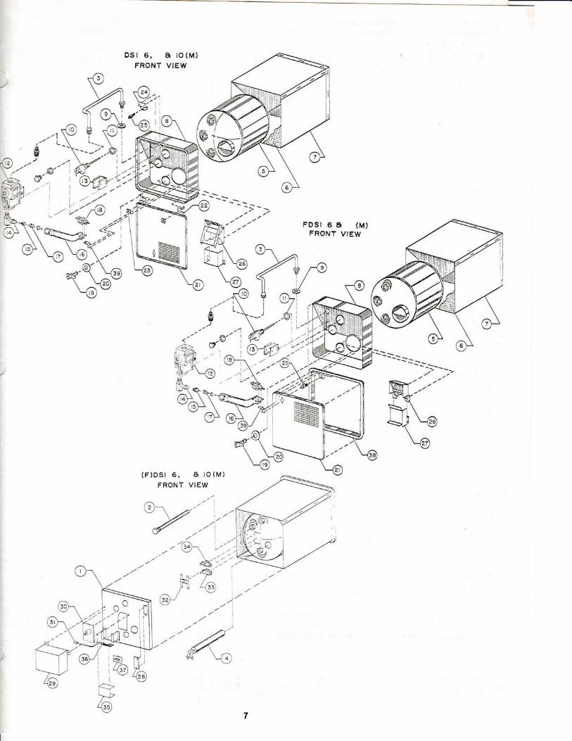
FDS| 6 I (M)FRONT VIEW
7
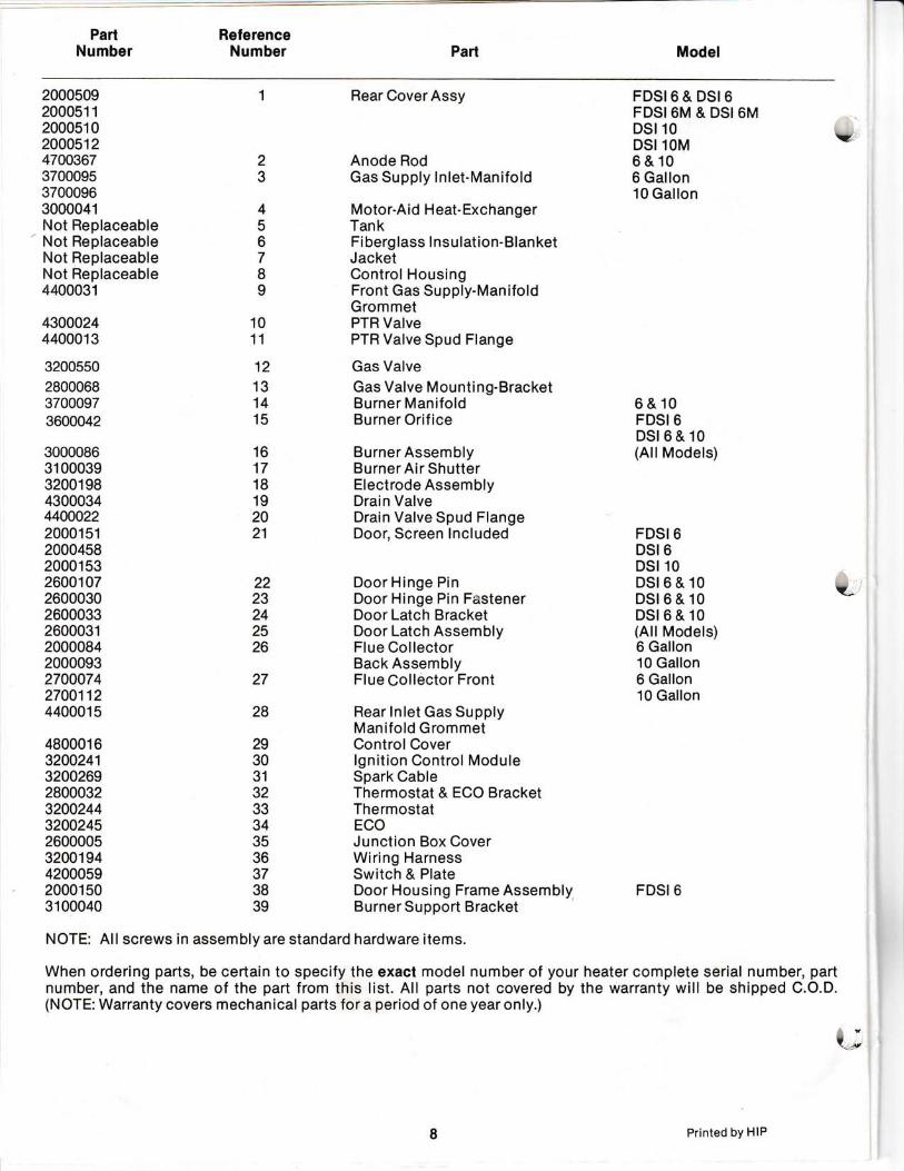
PartNumber
RelerenceNumber Part Model
2000s09200051 1
200051 020045124700367370009537000963000041Not ReplaceableNot ReplaceableNot ReplaceableNot Replaceable4400031
43000244400013
3200550
280006837000973600042
3000086310003932001 984300034440002220001512000458200015326001 072600030260003326000312000084200009327000742700112440001 5
48000163200241320026928000323200244320024526000053200194420005920001503100040
23
Rear CoverAssy
Anode RodGas Supply lnlet-Manifold
Motor-Aid H eat- ExchangerTankFi berg lass I nsulation-BlanketJacketControl HousingFront Gas Supply-ManifoldGrommetPTR ValvePTR Valve Spud Flange
Gas ValveGas Valve Mounti ng-BracketBurner ManifoldBurner Orif ice
BurnerAssemblyBurnerAir ShutterElectrode AssemblyDrain ValveDrain Valve Spud FlangeDoor, Screen lncluded
Door Hinge PinDoor Hinge Pin FastenerDoor Latch BracketDoor Latch AssemblyFlue CollectorBack AssemblyFlue Collector Front
Rear lnlet Gas SupplyManifold GrommetControlCoverlgnition Control ModuleSpark CableThermostat & ECO BracketThermostatECOJunction Box CoverWiring HarnessSwitch & PlateDoor Housing Frame AssemblyBurner Support Bracket
FDSI6&DSI6FDSI 6M & DSI 6MDSIlODSI lOM \q6&106 Gallon10 Gallon
6&10FDSI 6DSt6&10(AllModels)
456789
1011
12
131415
16171B192021
2223242526
27
FDSI 6DSI 6DSIlODSt6 & 10 cDSl6&10DSt6&10(All Models)6 Gallon10 Gallon6 Gallon10 Gallon
28
2930313233343536373839
FDSI 6
NOTE: All screws in assembly are standard hardware items.
When ordering parts, be certain to specify the exact model number of your heater complete serial number, partnumber, and the name of the part from this list. All parts not covered by the warranty will be shipped C.O.D.(NOTE: Warranty covers mechanical parts for a period of one year only.)
U
Printed bY HIP