DIRECT VENT GAS FIREPLACE - Kirkland Fireplace -...
48
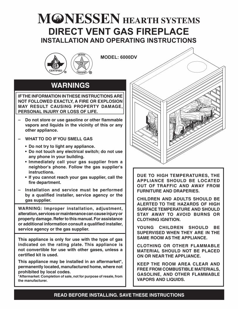
MODEL: 6000DV DIRECT VENT GAS FIREPLACE INSTALLATION AND OPERATING INSTRUCTIONS WARNINGS IF THE INFORMATION IN THESE INSTRUCTIONS ARE NOT FOLLOWED EXACTLY, A FIRE OR EXPLOSION MAY RESULT CAUSING PROPERTY DAMAGE, PERSONAL INJURY OR LOSS OF LIFE. – Do not store or use gasoline or other flammable vapors and liquids in the vicinity of this or any other appliance. – WHAT TO DO IF YOU SMELL GAS • Do not try to light any appliance. • Do not touch any electrical switch; do not use any phone in your building. • Immediately call your gas supplier from a neighbor's phone. Follow the gas supplier's instructions. • If you cannot reach your gas supplier, call the fire department. – Installation and service must be performed by a qualified installer, service agency or the gas supplier. WARNING: Improper installation, adjustment, alteration, services or maintenance can cause injury or property damage. Refer to this manual. For assistance or additional information consult a qualified installer, service agency or the gas supplier. This appliance is only for use with the type of gas indicated on the rating plate. This appliance is not convertible for use with other gases, unless a certified kit is used. This appliance may be installed in an aftermarket*, permanently located, manufactured home, where not prohibited by local codes. *Aftermarket: Completion of sale, not for purpose of resale, from the manufacturer. DUE TO HIGH TEMPERATURES, THE APPLIANCE SHOULD BE LOCATED OUT OF TRAFFIC AND AWAY FROM FURNITURE AND DRAPERIES. CHILDREN AND ADULTS SHOULD BE ALERTED TO THE HAZARDS OF HIGH SURFACE TEMPERATURE AND SHOULD STAY AWAY TO AVOID BURNS OR CLOTHING IGNITION. YOUNG CHILDREN SHOULD BE SUPERVISED WHEN THEY ARE IN THE SAME ROOM AS THE APPLIANCE. CLOTHING OR OTHER FLAMMABLE MATERIAL SHOULD NOT BE PLACED ON OR NEAR THE APPLIANCE. KEEP THE ROOM AREA CLEAR AND FREE FROM COMBUSTIBLE MATERIALS, GASOLINE, AND OTHER FLAMMABLE VAPORS AND LIQUIDS. READ BEFORE INSTALLING. SAVE THESE INSTRUCTIONS
Transcript of DIRECT VENT GAS FIREPLACE - Kirkland Fireplace -...
MODEL: 6000DV
DIRECT VENT GAS FIREPLACEINSTALLATION AND OPERATING INSTRUCTIONS
WARNINGSIF THE INFORMATION IN THESE INSTRUCTIONS ARE NOT FOLLOWED EXACTLY, A FIRE OR EXPLOSION MAY RESULT CAUSING PROPERTY DAMAGE, PERSONAL INJURY OR LOSS OF LIFE.
– Do not store or use gasoline or other flammable vapors and liquids in the vicinity of this or any other appliance.
– WHAT TO DO IF YOU SMELL GAS
• Do not try to light any appliance. • Do not touch any electrical switch; do not use
any phone in your building. • Immediately call your gas supplier from a
neighbor's phone. Follow the gas supplier's instructions.
• If you cannot reach your gas supplier, call the fire department.
– Installation and service must be performed by a qualified installer, service agency or the gas supplier.
WARNING: Improper installation, adjustment, alteration, services or maintenance can cause injury or property damage. Refer to this manual. For assistance or additional information consult a qualified installer, service agency or the gas supplier.
This appliance is only for use with the type of gas indicated on the rating plate. This appliance is not convertible for use with other gases, unless a certified kit is used.
This appliance may be installed in an aftermarket*, permanently located, manufactured home, where not prohibited by local codes.*Aftermarket: Completion of sale, not for purpose of resale, from the manufacturer.
DUE TO HIGH TEMPERATURES, THE APPLIANCE SHOULD BE LOCATED OUT OF TRAFFIC AND AWAY FROM FURNITURE AND DRAPERIES.
CHILDREN AND ADULTS SHOULD BE ALERTED TO THE HAZARDS OF HIGH SURFACE TEMPERATURE AND SHOULD STAY AWAY TO AVOID BURNS OR CLOTHING IGNITION.
YOUNG CHILDREN SHOULD BE SUPERVISED WHEN THEY ARE IN THE SAME ROOM AS THE APPLIANCE.
CLOTHING OR OTHER FLAMMABLE MATERIAL SHOULD NOT BE PLACED ON OR NEAR THE APPLIANCE.
KEEP THE ROOM AREA CLEAR AND FREE FROM COMBUSTIBLE MATERIALS, GASOLINE, AND OTHER FLAMMABLE VAPORS AND LIQUIDS.
READ BEFORE INSTALLING. SAVE THESE INSTRUCTIONS
2 42D0200 42D0200 3
CONTENTS
Important Safety Information .......................... 3
Code Approval .................................................. 4
Product Features.............................................. 5
Pre-Installation InformationInstalling Above 2000 Feet............................ 6Orifice Sizes, Pressures and BTUs............... 6Before You Install .......................................... 6Fireplace Dimensions ................................... 7Fireplace Location......................................... 8
Fireplace Framing ......................................... 10Framing Peninsula Fireplace ...................... 10Framing Corner Fireplace ............................11Framing See Through Fireplace ................. 12Securing Fireplace to Floor or Framing.. 13
Clearances ...................................................... 14
Installation Information.................................. 15
Vent Installation.............................................. 16Installation Precautions............................... 16Optional Top Vent Application ..................... 17Installation Planning.................................... 18Installation for Vertical Termination ............. 18Rear Wall Vent Installation .......................... 21Horizontal Termination Configuration .......... 23Below Grade Installation ............................. 24Vertical Through-the-Roof Installation......... 26Installation for Vertical Termination ............. 27Flat Ceiling Installation................................ 27
Fireplace Installation...................................... 29Check Gas Type.......................................... 29Installing Gas Piping to Fireplace/Burner System Location ......................................... 29
Checking Gas Pressure ................................. 30
Electrical Installation ..................................... 32Electrical Wiring .......................................... 32Remote Wall Switch .................................... 32
Glass Removal................................................ 33
Log Placement................................................ 34
Air Restrictor Adjustment.............................. 37
Operating Instructions................................... 38What To Do If You Smell Gas...................... 38Lighting Pilot for the First Time ................... 38Lighting Pilot ............................................... 39Lighting Burner............................................ 39To Turn Off Gas........................................... 39
Maintenance.................................................... 41Venting System ........................................... 41Cleaning Glass............................................ 41Pilot and Burner Flames ............................. 41Firebox Cleaning......................................... 41
Troubleshooting ............................................. 42
Blower.............................................................. 43
Replacement Parts ......................................... 44
Warranty ...........................................Back Cover
2 42D0200 42D0200 3
4. Never install the fireplace • in a recreational vehicle • where curtains, furniture, clothing, or other flammable
objects are less than 42" from the front, top, or sides of the fireplace
• in high traffic areas • in windy or drafty areas
5. This fireplace reaches high temperatures. Keep children and adults away from hot surfaces to avoid burns or cloth-ing ignition. Fireplace will remain hot for a time after shutdown. Allow surfaces to cool before touching.
6. Carefully supervise young children when they are in the room with fireplace.
7. Do not modify fireplace under any circumstances. Any parts removed for servicing must be replaced prior to operating fireplace.
8. Turn fireplace off and let cool before servicing, install-ing, or repairing. Only a qualified service person should install, service, or repair the fireplace. Have burner system inspected annually by a qualified service person.
9. You must keep control compartments, burners, and cir-culating air passages clean. More frequent cleaning may be needed due to excessive lint and dust from carpeting, bedding material, pet hair, etc. Turn off the gas valve and pilot light before cleaning fireplace.
10. Have venting system inspected annually by a qualified service person. If needed, have venting system cleaned or repaired. See Cleaning and Maintenance, page 39.
11. Keep the area around your fireplace clear of combustible materials, gasoline, and other flammable vapor and liq-uids. Do not run fireplace where these are used or stored. Do not place items such as clothing or decorations on or around fireplace.
INSTALLERPlease leave these instructions with the owner.
OWNERPlease retain these instructions for future reference.
IMPORTANT SAFETY INFORMATION
This fireplace is a vented product. This fireplace must be prop-erly installed by a qualified service person. The glass door must be properly seated and sealed. If this unit is not properly installed by a qualified service person with glass door properly seated and sealed, combustion leakage can occur.
CARBON MONOXIDE POISONING: Early signs of carbon monoxide poisoning are similar to the flu with head-aches, dizziness and/or nausea. If you have these signs, the fireplace may not have been installed properly. Get fresh air at once! Have the fireplace inspected and serviced by a quali-fied service person. Some people are more affected by carbon monoxide than others. These include pregnant women, people with heart or lung disease or anemia, those under the influence of alcohol, and those at high altitudes.
Propane/LP gas and natural gas are both odorless. An odor-making agent is added to each of these gases. The odor helps you detect a gas leak. However, the odor added to these gases can fade. Gas may be present even though no odor exists.
Make certain you read and understand all warnings. Keep this manual for reference. It is your guide to safe and proper operation of this fireplace.
1. This appliance is only for use with the type of gas indi-cated on the rating plate. This appliance is not convertible for use with other gases unless a certified kit is used.
2. For propane/LP fireplace, do not place propane/LP supply tank(s) inside any structure. Locate propane/LP supply tank(s) outdoors. To prevent performance problems, do not use propane/LP fuel tank of less than 100 gal. capacity.
3. If you smell gas • shut off gas supply. • do not try to light any appliance. • do not touch any electrical switch; do not use any
phone in your building . • immediately call your gas supplier from a neighbor’s
phone. Follow the gas supplier’s instructions.Continued on page 4
• Read this owner’s manual carefully and completely before trying to assemble, operate, or service this fireplace.
• Any change to this fireplace or its controls can be dangerous.
• Improper installation or use of this fireplace can cause serious injury or death from fire, burns, explosions, electrical shock and carbon monoxide poisoning.W
AR
NIN
G
4 42D0200 42D0200 5
IMPORTANT SAFETY INFORMATION AND CODE APPROVAL
Continued from page 3
12. Do not use this fireplace to cook food or burn paper or other objects.
13. Never place anything on top of fireplace.
14. Do not use any solid fuels (wood, coal, paper, cardboard, etc.) in this fireplace. Use only the gas type indicated on rating plate.
15. This appliance, when installed, must be electrically grounded in accordance with local codes or in the absence of local codes, with the National Electrical Code, ANSI/NFPA 70, or the Canadian Electrical Code, CSA C22.1.
16. Do not obstruct the flow of combustion and ventilation air in any way. Provide adequate clearances around air openings into the combustion chamber along with adequate accessibility clearance for servicing and proper operation.
17. When the appliance is installed directly on carpeting, tile or other combustible material other than wood floor-ing, you must set appliance on a metal or wood panel or hearth pad extending the full width and depth of the appliance.
18. Do not use fireplace if any part has been exposed to or under water. Immediately call a qualified service person to arrange for replacement of the unit.
19. Do not operate fireplace if any log is broken.
20. Do not use a blower insert, heat exchanger insert, or any other accessory not approved for use with this fire-place.
21. Do not operate the fireplace with glass door removed, cracked, or broken.
22. This unit is approved for bedrooms and bathrooms.
CODE APPROVAL
Direct Vent type appliances draw all combustion air from outside of the dwelling through the vent pipe.
These appliances have been tested by CSA and found to comply with the established standards for DIRECT VENT GAS FIREPLACE HEATERS in the USA and Canada as follows:
LISTED VENTED GAS FIREPLACE HEATERTESTED TO: ANSI Z21.88-2002/CSA 2.33-2002 STANDARDS
IMPORTANT:
PLEASE READ THE FOLLOWING CAREFULLY It is normal for fireplaces fabricated of steel to give off some expansion and/or contraction noises during the start up or cool down cycle. Similar noises are found with your furnace heat exchanger or car engine.
IMPORTANT:
PLEASE READ THE FOLLOWING CAREFULLY It is not unusual for gas fireplace to give off some odor the first time it is burned. This is due to the manufacturing process. Please ensure that your room is well ventilated
during burn off — open all windows.It is recommended that you burn your fireplace for at least ten (10) hours the first time you use it. Place the fan switch in the “OFF” position during this time.
4 42D0200 42D0200 5
PRODUCT FEATURES AND CODE APPROVAL
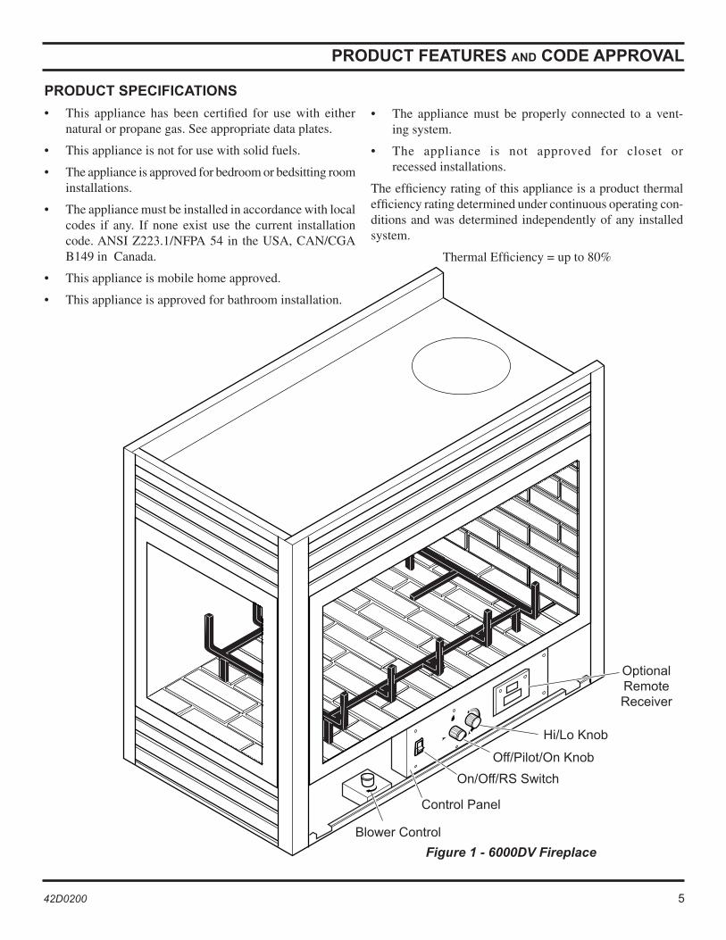
Off/Pilot/On Knob
Optional Remote Receiver
Figure 1 - 6000DV Fireplace
Hi/Lo Knob
PRODUCT SPECIFICATIONS
• This appliance has been certified for use with either natural or propane gas. See appropriate data plates.
• This appliance is not for use with solid fuels.
• The appliance is approved for bedroom or bedsitting room installations.
• The appliance must be installed in accordance with local codes if any. If none exist use the current installation code. ANSI Z223.1/NFPA 54 in the USA, CAN/CGA B149 in Canada.
• This appliance is mobile home approved.
• This appliance is approved for bathroom installation.
Blower Control
On/Off/RS Switch
• The appliance must be properly connected to a vent-ing system.
• The appliance is not approved for closet or recessed installations.
The efficiency rating of this appliance is a product thermal efficiency rating determined under continuous operating con-ditions and was determined independently of any installed system.
Thermal Efficiency = up to 80%
Control Panel
6 42D0200 42D0200 7
PRE-INSTALLATION INFORMATION
INSTALLING ABOVE 2000 FEET
• In the USA, the appliance must be derated 4% for every 1,000 ft above 2,000 ft elevations.
• In Canada, these appliances are certified for altitudes of 0 – 2000 ft, and must be de-rated by 10 percent for installations between 2000 and 4,500 ft. (derate an additional 4% for every 1,000 ft. above 4,500 ft. elevations).
• Contact gas supplier.
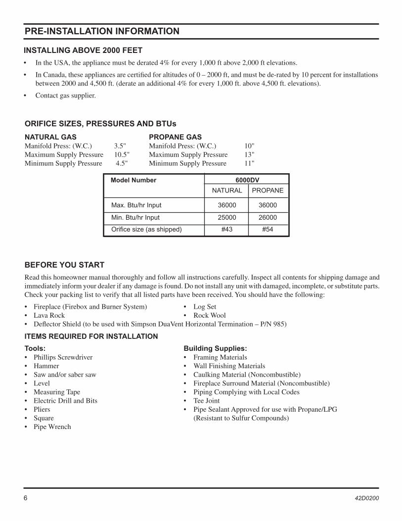
ORIFICE SIZES, PRESSURES AND BTUs
NATURAL GAS PROPANE GASManifold Press: (W.C.) 3.5" Manifold Press: (W.C.) 10" Maximum Supply Pressure 10.5" Maximum Supply Pressure 13" Minimum Supply Pressure 4.5" Minimum Supply Pressure 11"
Model Number 6000DV
NATURAL PROPANE
Max. Btu/hr Input 36000 36000
Min. Btu/hr Input 25000 26000
Orifice size (as shipped) #43 #54
BEFORE YOU START
Read this homeowner manual thoroughly and follow all instructions carefully. Inspect all contents for shipping damage and immediately inform your dealer if any damage is found. Do not install any unit with damaged, incomplete, or substitute parts. Check your packing list to verify that all listed parts have been received. You should have the following:
• Fireplace (Firebox and Burner System) • Log Set• Lava Rock • Rock Wool • Deflector Shield (to be used with Simpson DuaVent Horizontal Termination – P/N 985)
ITEMS REQUIRED FOR INSTALLATION
Tools: Building Supplies:• Phillips Screwdriver • Framing Materials• Hammer • Wall Finishing Materials• Saw and/or saber saw • Caulking Material (Noncombustible) • Level • Fireplace Surround Material (Noncombustible)• Measuring Tape • Piping Complying with Local Codes• Electric Drill and Bits • Tee Joint• Pliers • Pipe Sealant Approved for use with Propane/LPG• Square (Resistant to Sulfur Compounds)• Pipe Wrench

6 42D0200 42D0200 7
������������
������
������
���
������
������������
��������
��������
��������
������
������
�����
������
������
�����
������
���
������
������ ��������������
PRE-INSTALLATION INFORMATION
Figure 2 - Fireplace Dimensions
SEE THROUGH AND PENINSULA UNITS
CORNER UNITS(RIGHT-HAND UNIT SHOWN)
Gas/Electric
8 42D0200 42D0200 9
PRE-INSTALLATION INFORMATION
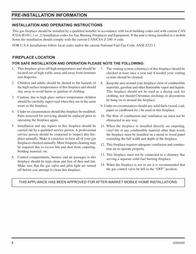
This gas fireplace should be installed by a qualified installer in accordance with local building codes and with current CAN /CGA-B149 (.1 or .2) Installation codes for Gas Burning Fireplaces and Equipment. If the unit is being installed in a mobile home the installation should comply with the current CAN/CSA Z 240 .4 code.
FOR U.S.A Installations follow local codes and/or the current National Fuel Gas Code. ANSI Z223.1.
FIREPLACE LOCATION
FOR SAFE INSTALLATION AND OPERATION PLEASE NOTE THE FOLLOWING:
INSTALLATION AND OPERATING INSTRUCTIONS
THIS APPLIANCE HAS BEEN APPROVED FOR AFTER-MARKET MOBILE HOME INSTALLATIONS.
1. This fireplace gives off high temperatures and should be located out of high traffic areas and away from furniture and draperies.
2. Children and adults should be alerted to the hazards of the high surface temperatures of this fireplace and should stay away to avoid burns or ignition of clothing.
3. Caution, due to high glass surface temperature children should be carefully supervised when they are in the same room as the fireplace.
4. Under no circumstances should this fireplace be modified. Parts removed for servicing should be replaced prior to operating the fireplace again.
5. Installation and any repairs to this fireplace should be carried out by a qualified service person. A professional service person should be contacted to inspect this fire-place annually. Make it a practice to have all of your gas fireplaces checked annually. More frequent cleaning may be required due to excess lint and dust from carpeting, bedding material, etc.
6. Control compartments, burners and air passages in this fireplace should be kept clean and free of dust and lint. Make sure that the gas valve and pilot light are turned off before you attempt to clean this fireplace.
7. The venting system (chimney) of this fireplace should be checked at least once a year and if needed your venting system should be cleaned.
8. Keep the area around your fireplace clear of combustible materials, gasoline and other flammable vapor and liquids. This fireplace should not be used as a drying rack for clothing, nor should Christmas stockings or decorations be hung on or around the fireplace.
9. Under no circumstances should any solid fuels (wood, coal, paper or cardboard etc.) be used in this fireplace.
10. The flow of combustion and ventilation air must not be obstructed in any way.
11. When the fireplace is installed directly on carpeting, vinyl tile or any combustible material other than wood, the fireplace must be installed on a metal or wood panel extending the full width and depth of the fireplace.
12. This fireplace requires adequate ventilation and combus-tion air to operate properly.
13. This fireplace must not be connected to a chimney flue serving a separate solid fuel burning fireplace.
14. When the fireplace is not in use it is recommended that the gas control valve be left in the “OFF” position.
8 42D0200 42D0200 9
�
�
�
�
�
�
�
�
�
�
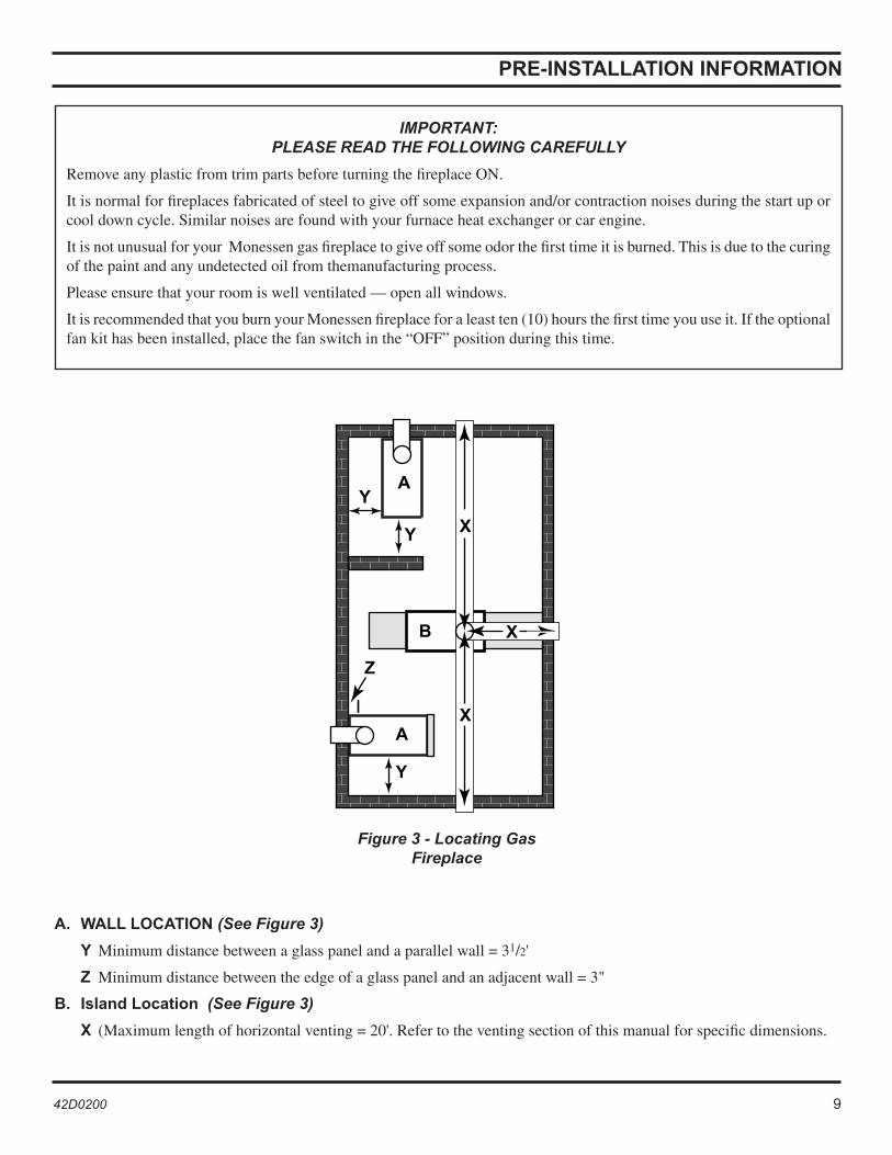
Figure 3 - Locating Gas Fireplace
A. WALL LOCATION (See Figure 3)
Y Minimum distance between a glass panel and a parallel wall = 31/2'
Z Minimum distance between the edge of a glass panel and an adjacent wall = 3"
B. Island Location (See Figure 3)
X (Maximum length of horizontal venting = 20'. Refer to the venting section of this manual for specific dimensions.
IMPORTANT: PLEASE READ THE FOLLOWING CAREFULLY
Remove any plastic from trim parts before turning the fireplace ON.
It is normal for fireplaces fabricated of steel to give off some expansion and/or contraction noises during the start up or cool down cycle. Similar noises are found with your furnace heat exchanger or car engine.
It is not unusual for your Monessen gas fireplace to give off some odor the first time it is burned. This is due to the curing of the paint and any undetected oil from themanufacturing process.
Please ensure that your room is well ventilated — open all windows.
It is recommended that you burn your Monessen fireplace for a least ten (10) hours the first time you use it. If the optional fan kit has been installed, place the fan switch in the “OFF” position during this time.
PRE-INSTALLATION INFORMATION
10 42D0200 42D0200 11
�
����
�
��
�
��
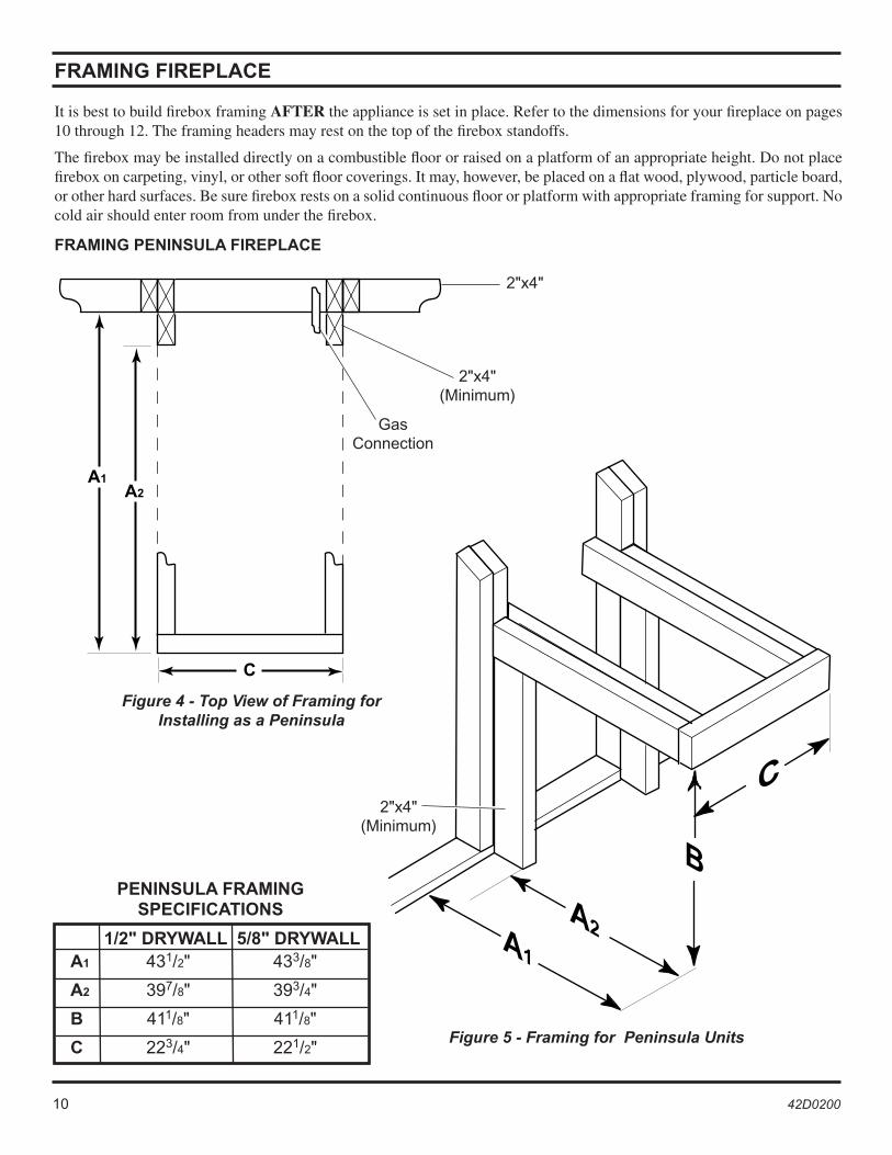
It is best to build firebox framing AFTER the appliance is set in place. Refer to the dimensions for your fireplace on pages 10 through 12. The framing headers may rest on the top of the firebox standoffs.
The firebox may be installed directly on a combustible floor or raised on a platform of an appropriate height. Do not place firebox on carpeting, vinyl, or other soft floor coverings. It may, however, be placed on a flat wood, plywood, particle board, or other hard surfaces. Be sure firebox rests on a solid continuous floor or platform with appropriate framing for support. No cold air should enter room from under the firebox.
Figure 4 - Top View of Framing for Installing as a Peninsula
Figure 5 - Framing for Peninsula Units
2"x4"
2"x4"(Minimum)
2"x4"(Minimum)
GasConnection
FRAMING FIREPLACE
FRAMING PENINSULA FIREPLACE
1/2" DRYWALL 5/8" DRYWALL A1 431/2" 433/8"
A2 397/8" 393/4"
B 411/8" 411/8"
C 223/4" 221/2"
PENINSULA FRAMING SPECIFICATIONS
10 42D0200 42D0200 11
�
��
��
�
��
�
�� �
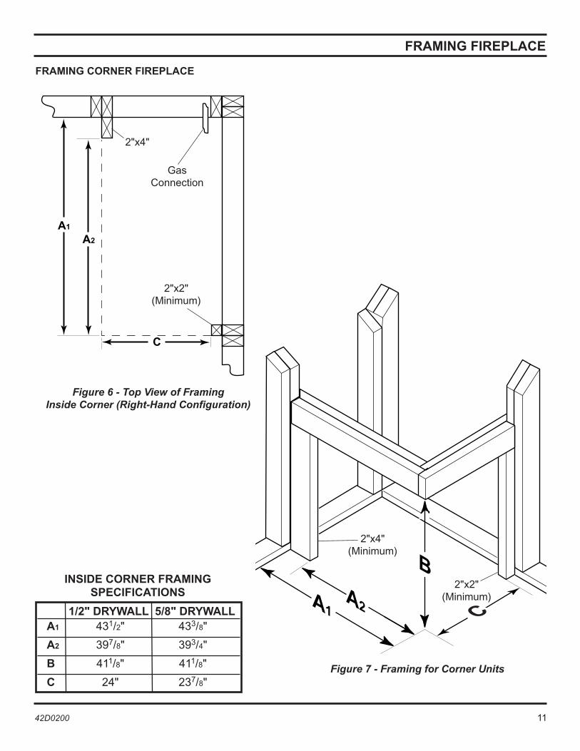
Figure 6 - Top View of Framing Inside Corner (Right-Hand Configuration)
Figure 7 - Framing for Corner Units
GasConnection
FRAMING CORNER FIREPLACE
1/2" DRYWALL 5/8" DRYWALL A1 431/2" 433/8"
A2 397/8" 393/4"
B 411/8" 411/8"
C 24" 237/8"
INSIDE CORNER FRAMING SPECIFICATIONS
2"x4"
2"x2"(Minimum)
2"x4"(Minimum)
2"x2"(Minimum)
FRAMING FIREPLACE
12 42D0200 42D0200 13
�
����
���
�
��
FRAMING FIREPLACE
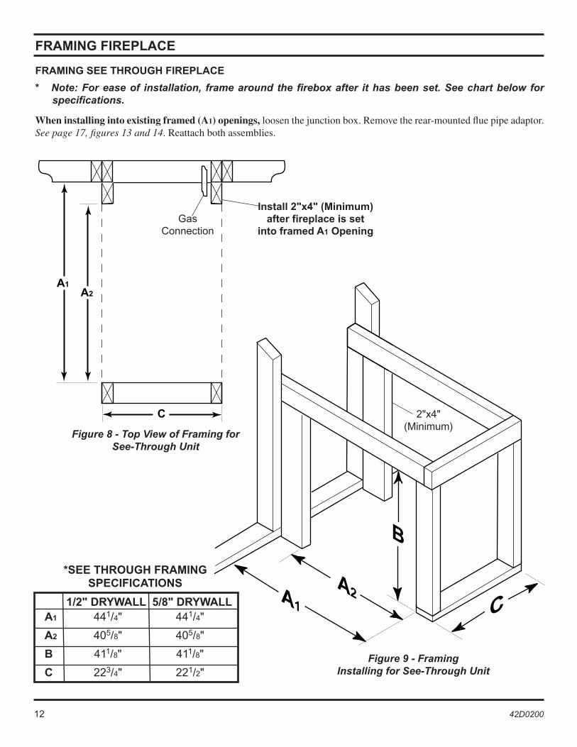
Figure 8 - Top View of Framing for See-Through Unit
Figure 9 - Framing Installing for See-Through Unit
GasConnection
2"x4"(Minimum)
Install 2"x4" (Minimum) after fireplace is set
into framed A1 Opening
1/2" DRYWALL 5/8" DRYWALL A1 441/4" 441/4"
A2 405/8" 405/8"
B 411/8" 411/8"
C 223/4" 221/2"
*SEE THROUGH FRAMING SPECIFICATIONS
FRAMING SEE THROUGH FIREPLACE
* Note: For ease of installation, frame around the firebox after it has been set. See chart below for specifications.
When installing into existing framed (A1) openings, loosen the junction box. Remove the rear-mounted flue pipe adaptor. See page 17, figures 13 and 14. Reattach both assemblies.
12 42D0200 42D0200 13
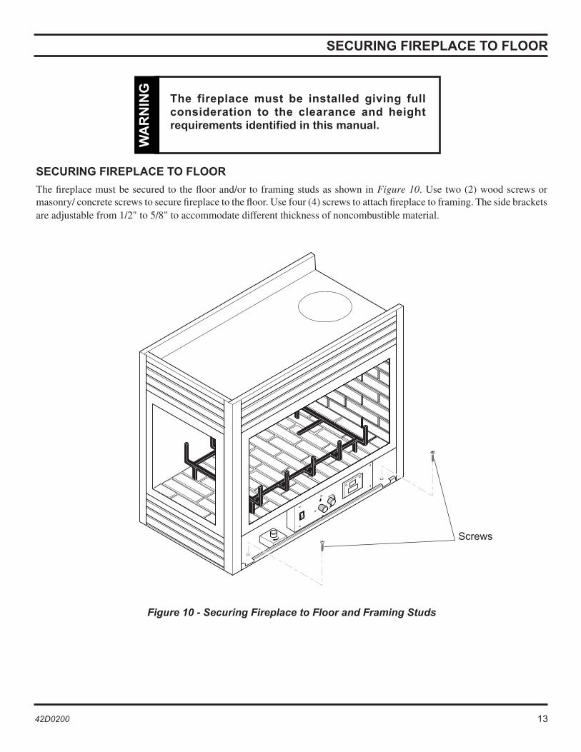
Figure 10 - Securing Fireplace to Floor and Framing Studs
Screws
SECURING FIREPLACE TO FLOOR
The fireplace must be secured to the floor and/or to framing studs as shown in Figure 10. Use two (2) wood screws or masonry/ concrete screws to secure fireplace to the floor. Use four (4) screws to attach fireplace to framing. The side brackets are adjustable from 1/2" to 5/8" to accommodate different thickness of noncombustible material.
The fireplace must be installed giving full consideration to the clearance and height requirements identified in this manual.
WA
RN
ING
SECURING FIREPLACE TO FLOOR
14 42D0200 42D0200 15
�
�
�
�
�
� � � � �
Follow these instructions carefully to ensure safe installation. Failure to follow instructions exactly can create a fire hazard.
The appliance cannot be installed on a carpet, tile or other combustible material other than wood flooring. If installed on carpet or vinyl flooring, the appliance shall be installed on a metal, wood or noncombustible material panel extending full width and depth of the appliance.W
AR
NIN
GCLEARANCES
CLEARANCES TO COMBUSTIBLES
MANTEL CLEARANCES
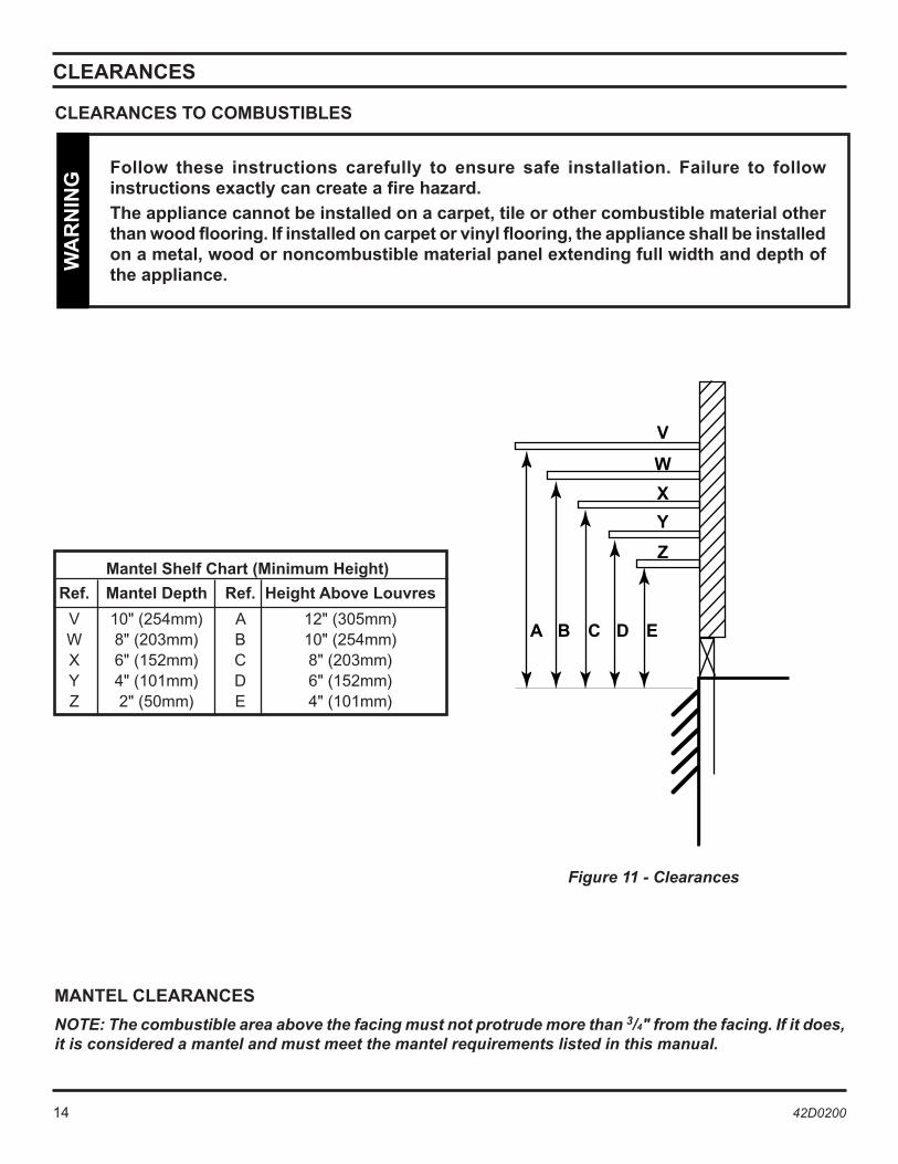
NOTE: The combustible area above the facing must not protrude more than 3/4" from the facing. If it does, it is considered a mantel and must meet the mantel requirements listed in this manual.
Figure 11 - Clearances
Mantel Shelf Chart (Minimum Height)
Ref. Mantel Depth Ref. Height Above Louvres
V 10" (254mm) A 12" (305mm) W 8" (203mm) B 10" (254mm) X 6" (152mm) C 8" (203mm) Y 4" (101mm) D 6" (152mm) Z 2" (50mm) E 4" (101mm)

14 42D0200 42D0200 15
Read all instructions completely and thoroughly before attempting installation. Failure to do so could result in serious injury, property damage or loss of life. Operation of improperly installed and maintained venting system could result in serious injury, property damage or loss of life.
WA
RN
ING
Failure to follow these instructions will void the warranty.
NO
TIC
E
INSTALLATION PRECAUTIONS
NOTE: This appliance must be installed with a Monessen approved venting system only.
Consult local building codes before beginning the installation. The installer must make sure to select the proper vent system for installation. Before installing vent kit, the installer must read this fireplace manual and vent kit instructions.
Only a qualified installer/service person should install venting system. The installer must follow these safety rules:
• Wear gloves and safety glasses for protection.
• Use extreme caution when using ladders or when on rooftops.
• Be aware of electrical wiring locations in walls and ceilings.
The following actions will void the warranty on your venting system:
• Installation of any damaged venting component.
• Unauthorized modification of the venting system.
• Installation of any component part not manufactured or approved by Monessen.
• Installation other than permitted by these instructions.
FINISHING MATERIAL
NOTE: Any remote wiring (i.e. remote control, wall switch, and optional fan) must be done prior to final finishing to avoid costly reconstruction.
INSTALLATION INFORMATION
Only noncombustible materials (i.e. brick, tile, slate, steel, or other materials with a UL fire rating of Zero) may be used to cover the black-painted face of the appliance. A 300°F minimum adhesive may be used to attach facing materials to the black surface. If joints between the finished wall and the fireplace surround are sealed, a 300°F minimum sealant material (General Electric RTV103 or equivalent) must be used. Combustibles may come to the top and side edges but not overlay the face.
Never obstruct or modify the air inlet or outlet grills (louvers). This may create a fire hazard.
WA
RN
ING
VENT INSTALLATION
16 42D0200 42D0200 17
1"
1"
1"
3"
3"
VENT INSTALLATION
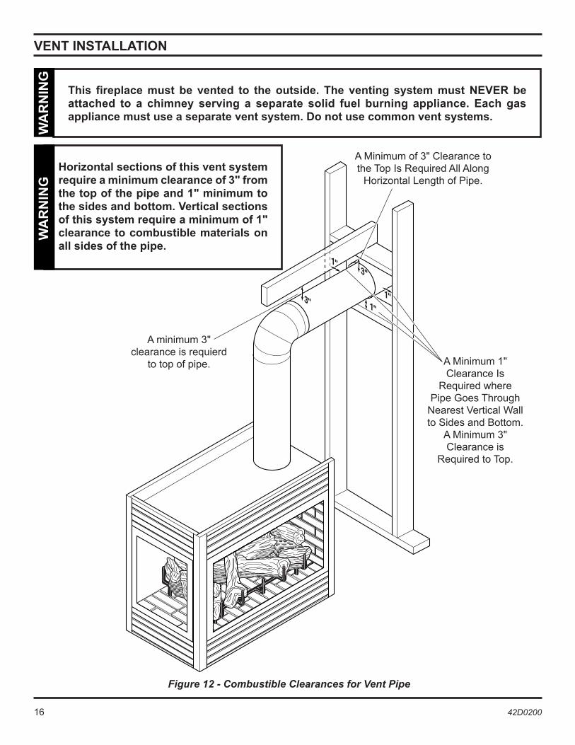
This fireplace must be vented to the outside. The venting system must NEVER be attached to a chimney serving a separate solid fuel burning appliance. Each gas appliance must use a separate vent system. Do not use common vent systems.
WA
RN
ING
Horizontal sections of this vent system require a minimum clearance of 3" from the top of the pipe and 1" minimum to the sides and bottom. Vertical sections of this system require a minimum of 1" clearance to combustible materials on all sides of the pipe.
Figure 12 - Combustible Clearances for Vent Pipe
A Minimum of 3" Clearance to the Top Is Required All Along
Horizontal Length of Pipe.
A Minimum 1" Clearance Is
Required where Pipe Goes Through
Nearest Vertical Wall to Sides and Bottom.
A Minimum 3" Clearance is
Required to Top.
WA
RN
ING
A minimum 3" clearance is requierd
to top of pipe.
16 42D0200 42D0200 17
VENT INSTALLATION
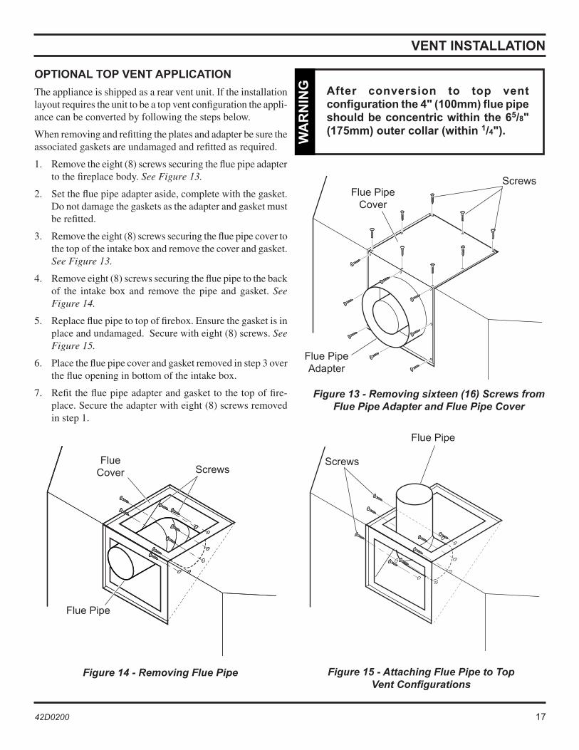
OPTIONAL TOP VENT APPLICATION
The appliance is shipped as a rear vent unit. If the installation layout requires the unit to be a top vent configuration the appli-ance can be converted by following the steps below.
When removing and refitting the plates and adapter be sure the associated gaskets are undamaged and refitted as required.
1. Remove the eight (8) screws securing the flue pipe adapter to the fireplace body. See Figure 13.
2. Set the flue pipe adapter aside, complete with the gasket. Do not damage the gaskets as the adapter and gasket must be refitted.
3. Remove the eight (8) screws securing the flue pipe cover to the top of the intake box and remove the cover and gasket. See Figure 13.
4. Remove eight (8) screws securing the flue pipe to the back of the intake box and remove the pipe and gasket. See Figure 14.
5. Replace flue pipe to top of firebox. Ensure the gasket is in place and undamaged. Secure with eight (8) screws. See Figure 15.
6. Place the flue pipe cover and gasket removed in step 3 over the flue opening in bottom of the intake box.
7. Refit the flue pipe adapter and gasket to the top of fire-place. Secure the adapter with eight (8) screws removed in step 1.
After conversion to top vent configuration the 4" (100mm) flue pipe should be concentric within the 65/8" (175mm) outer collar (within 1/4").
WA
RN
ING
Figure 13 - Removing sixteen (16) Screws from Flue Pipe Adapter and Flue Pipe Cover
Figure 14 - Removing Flue Pipe Figure 15 - Attaching Flue Pipe to Top Vent Configurations
Screws Flue Pipe
Cover
Flue Pipe Adapter
Flue Cover
Flue Pipe
Screws
Flue Pipe
Screws
18 42D0200 42D0200 19
VENT INSTALLATION
INSTALLATION PLANNING
There are two basic types of direct-vent installation: • Horizontal Termination • Vertical Termination
It is important to select the proper length of vent pipe for the type of termination you choose. It is also important to note the wall thickness.
FOR HORIZONTAL TERMINATION
Select the amount of vertical rise desired. All horizontal run of venting must have 1/4" rise for every 12" of run towards the termination.
You may use up to three 90° elbows in this vent configuration. See Horizontal Termination Configurations on pages 23 and 24.
FOR VERTICAL TERMINATION
Measure the distance from the fireplace floor to the ceiling. Add the ceiling thickness, the vertical rise in an attic or second story, and allow for sufficient vent height above the roof line.
NOTE: You may use two 45° elbows in place of a 90° elbow. You must follow rise to run ratios when using 45° elbows. The appliance is approved for use with three 90° elbows maximum or a combination of 90° and 45° elbows up to a maximum of 270°.
For two-story applications, firestops are required at each floor level. If an offset is needed in the attic, additional pipe and elbows will be required.
You may use a chase with a vent termination with exposed pipe on the exterior of the house. See Installing Vent System in a Chase below. If pipe is enclosed in chase, it is not exposed.
It is very important that the venting system maintain its balance between the combustion air intake and the flue gas exhaust. Certain limitations apply to vent configurations and must be strictly followed.
INSTALLING A VENT SYSTEM IN AN OUTSIDE CHASE
A chase is a vertical boxlike structure built to enclose venting that runs along the outside of a building. A chase is required for such venting.
Never run the vent pipe level or downward. This may cause excessive temperatures which could cause a fire. W
AR
NIN
G
Treatment of firestops and construction of the chase may vary from building type to building type. These instructions are not substitutes for the requirements of local building codes. You must follow all local building codes.
NO
TIC
E
When installing in a chase, you should insulate the chase as you would the outside walls of your home. This is especially important in cold climates. Insulation should be considered a combustible material. Maintain proper clearances to all combustible materials. N
OT
ICE
18 42D0200 42D0200 19
�
�
�
�
��
�
�
�
�
�
�
�
�
�
�
� �
��
�
�
�
�
�
�
�
��������
����������� �����
������������
���
�
�
��
�
VENT INSTALLATION
Always maintain minimum clearances around vent systems. The minimum clearances to combustibles for horizontal vent pipe are 3" at the top and 1" at the sides and bottom of the vent system until the pipe penetrates the nearest vertical wall. A 1" minimum clearance all around the pipe must be maintained. Do not pack the open air spaces with insulation or other materials. This could cause high temperatures and may present a fire hazard.W
AR
NIN
G
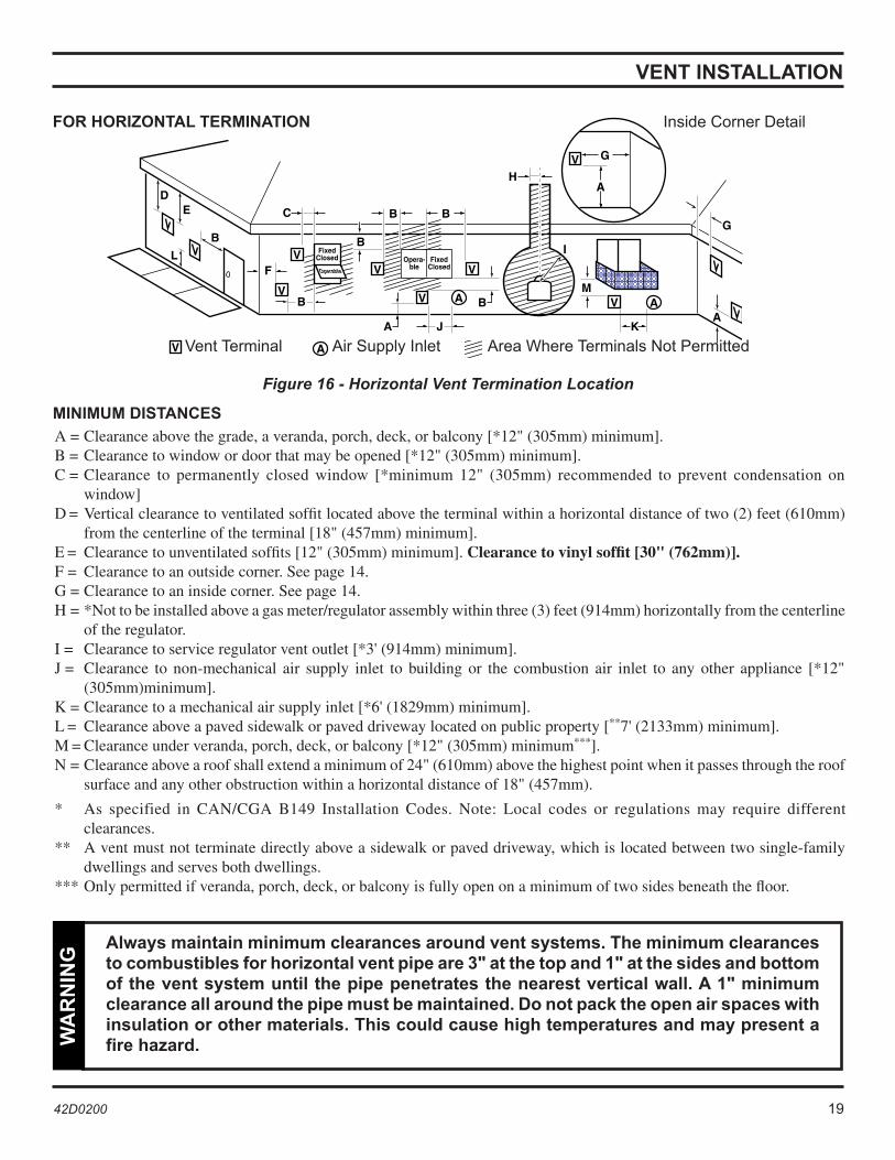
Figure 16 - Horizontal Vent Termination Location
Vent Terminal Air Supply Inlet Area Where Terminals Not Permitted
Inside Corner Detail FOR HORIZONTAL TERMINATION
MINIMUM DISTANCES
A = Clearance above the grade, a veranda, porch, deck, or balcony [*12" (305mm) minimum]. B = Clearance to window or door that may be opened [*12" (305mm) minimum]. C = Clearance to permanently closed window [*minimum 12" (305mm) recommended to prevent condensation on
window] D = Vertical clearance to ventilated soffit located above the terminal within a horizontal distance of two (2) feet (610mm)
from the centerline of the terminal [18" (457mm) minimum]. E = Clearance to unventilated soffits [12" (305mm) minimum]. Clearance to vinyl soffit [30" (762mm)]. F = Clearance to an outside corner. See page 14. G = Clearance to an inside corner. See page 14. H = *Not to be installed above a gas meter/regulator assembly within three (3) feet (914mm) horizontally from the centerline
of the regulator. I = Clearance to service regulator vent outlet [*3' (914mm) minimum]. J = Clearance to non-mechanical air supply inlet to building or the combustion air inlet to any other appliance [*12"
(305mm)minimum]. K = Clearance to a mechanical air supply inlet [*6' (1829mm) minimum]. L = Clearance above a paved sidewalk or paved driveway located on public property [**7' (2133mm) minimum]. M = Clearance under veranda, porch, deck, or balcony [*12" (305mm) minimum***].N = Clearance above a roof shall extend a minimum of 24" (610mm) above the highest point when it passes through the roof
surface and any other obstruction within a horizontal distance of 18" (457mm).
* As specified in CAN/CGA B149 Installation Codes. Note: Local codes or regulations may require different clearances.
** A vent must not terminate directly above a sidewalk or paved driveway, which is located between two single-family dwellings and serves both dwellings.
*** Only permitted if veranda, porch, deck, or balcony is fully open on a minimum of two sides beneath the floor.
20 42D0200 42D0200 21
�
� ���� �������
� ���� �������
�
�
�
� � ����������� ������������������������ ����������
����������� ���������������� � ��� �������� � ��� �������
�
�
�
� �������� ����� �� ��� ����������� ������ ��������
� �������� ����� ��� ���� ���� �������� ������������������� � ��� ��������������������� � ��� �������
� ���������� ���� ������ �� ������������������������� � �� ��������������������� � �� ������
��
���
������ ������
������ ��������
������� ������
������� ���� �� ���� ���� ������� ���� ����������������� ����
������������������������������������
� � � � �������� ����
��� �
VENT INSTALLATION
TERMINATION CLEARANCES FOR BUILDINGS WITH COMBUSTIBLE AND NONCOMBUSTIBLE EXTERIORS
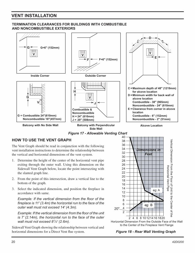
Figure 17 - Allowable Venting Chart
HOW TO USE THE VENT GRAPH
The Vent Graph should be read in conjunction with the following vent installation instructions to determine the relationship between the vertical and horizontal dimensions of the vent system.
1. Determine the height of the center of the horizontal vent pipe exiting through the outer wall. Using this dimension on the Sidewall Vent Graph below, locate the point intersecting with the slanted graph line.
2. From the point of this intersection, draw a vertical line to the bottom of the graph.
3. Select the indicated dimension, and position the fireplace in accordance with same.
Example: If the vertical dimension from the floor of the fireplace is 11' (3.4m) the horizontal run to the face of the outer wall must not exceed 14' (4.3m).
Example: If the vertical dimension from the floor of the unit is 7’ (2.14m), the horizontal run to the face of the outer wall must not exceed 81/2' (2.6m).
Sidewall Vent Graph showing the relationship between vertical and horizontal dimensions for a Direct Vent flue system. Figure 18 - Rear Wall Venting Graph
Horizontal Dimension From the Outside Face of the Wall to the Center of the Fireplace Vent Flange
Vertical D
imension F
rom the F
loor of Unit to the C
enter of the H
orizontal Vent P
ipe
Dimensions in Feet
20"
20 42D0200 42D0200 21
������������
�������������
�����������
������������
REAR WALL VENT INSTALLATION
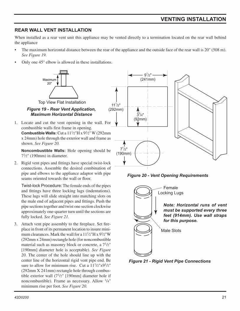
When installed as a rear vent unit this appliance may be vented directly to a termination located on the rear wall behind the appliance
• The maximum horizontal distance between the rear of the appliance and the outside face of the rear wall is 20" (508 m). See Figure 19.
• Only one 45° elbow is allowed in these installations.
VENTING INSTALLATION
Note: Horizontal runs of vent must be supported every three feet (914mm). Use wall straps for this purpose.
Figure 21 - Rigid Vent Pipe Connections
Female Locking Lugs
Male Slots
Figure 20 - Vent Opening Requirements
1. Locate and cut the vent opening in the wall. For combustible walls first frame in opening. Combustible Walls: Cut a 111⁄2"H x 91⁄2" W (292mm x 24mm) hole through the exterior wall and frame as shown. See Figure 20.
Noncombustible Walls: Hole opening should be 71⁄2" (190mm) in diameter.
2. Rigid vent pipes and fittings have special twist-lock connections. Assemble the desired combination of pipe and elbows to the appliance adaptor with pipe seams oriented towards the wall or floor.
Twist-lock Procedure: The female ends of the pipes and fittings have three locking lugs (indentations). These lugs will slide straight into matching slots on the male end of adjacent pipes and fittings. Push the pipe sections together and twist one section clockwise approximately one-quarter turn until the sections are fully locked. See Figure 21.
3. Attach vent pipe assembly to the fireplace. Set fire-place in front of its permanent location to insure mini-mum clearances. Mark the wall for a 111⁄2"H x 91⁄2"W (292mm x 24mm) rectangle hole (for noncombustible material such as masonry block or concrete, a 71/2" [190mm] diameter hole is acceptable). See Figure 20. The center of the hole should line up with the center line of the horizontal rigid vent pipe end. Be sure to allow for minimum rise. Cut a 111/2"x91/2" (292mm X 241mm) rectangle hole through combus-tible exterior wall (71/2" [190mm] diameter hole if noncombustible). Frame as necessary. Allow 1/4" minimum rise per foot. See Figure 20.
Figure 19 - Rear Vent Application,Maximum Horizontal Distance
Top View Flat Installation
22 42D0200 42D0200 23
HOT
HOT
VENT INSTALLATION
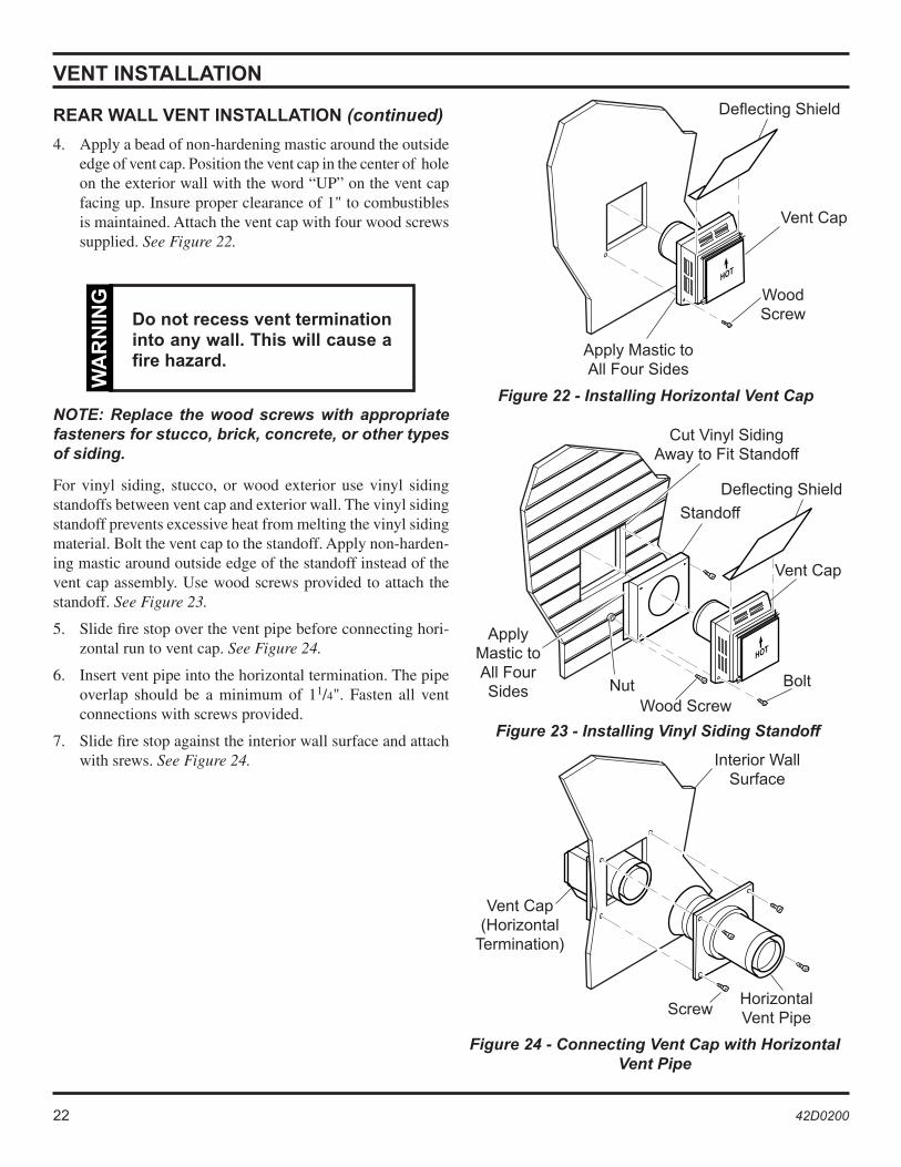
4. Apply a bead of non-hardening mastic around the outside edge of vent cap. Position the vent cap in the center of hole on the exterior wall with the word “UP” on the vent cap facing up. Insure proper clearance of 1" to combustibles is maintained. Attach the vent cap with four wood screws supplied. See Figure 22.
Do not recess vent termination into any wall. This will cause a fire hazard.
WA
RN
ING
NOTE: Replace the wood screws with appropriate fasteners for stucco, brick, concrete, or other types of siding.
For vinyl siding, stucco, or wood exterior use vinyl siding standoffs between vent cap and exterior wall. The vinyl siding standoff prevents excessive heat from melting the vinyl siding material. Bolt the vent cap to the standoff. Apply non-harden-ing mastic around outside edge of the standoff instead of the vent cap assembly. Use wood screws provided to attach the standoff. See Figure 23.
5. Slide fire stop over the vent pipe before connecting hori-zontal run to vent cap. See Figure 24.
6. Insert vent pipe into the horizontal termination. The pipe overlap should be a minimum of 11/4". Fasten all vent connections with screws provided.
7. Slide fire stop against the interior wall surface and attach with srews. See Figure 24.
Figure 22 - Installing Horizontal Vent Cap
REAR WALL VENT INSTALLATION (continued)
Figure 23 - Installing Vinyl Siding Standoff
Apply Mastic to All Four Sides
Vent Cap
Wood Screw
Cut Vinyl Siding Away to Fit Standoff
Wood Screw
Vent Cap
Bolt
Apply Mastic to All Four Sides
Nut
Standoff
Figure 24 - Connecting Vent Cap with Horizontal Vent Pipe
Interior Wall Surface
Horizontal Vent Pipe Screw
Vent Cap (Horizontal
Termination)
Deflecting Shield
Deflecting Shield
22 42D0200 42D0200 23
VENT INSTALLATION
HORIZONTAL TERMINATION CONFIGURATIONS
Since it is very important that the venting system maintain its balance between the combustion air intake and the flue gas exhaust, certain limitations as to vent configurations apply and must be strictly adhered to.
The Vent Graph, showing the relationship between vertical and horizontal side wall venting, will help to determine the vari-ous dimensions allowable. See page 20.
Minimum clearance between vent pipes and combustible materials is 3" on top and 1" from bottom and sides unless otherwise noted.
When vent termination exits through foundations less than 20" below siding outcrop, the vent pipe must flush up with the siding.
It is best to locate the fireplace in such a way that minimizes the number of offsets and horizontal vent length.
The horizontal vent run refers to the total length of vent pipe from the flue collar of the fireplace (or the top of he Transi-tion Elbow) to the face of the outer wall.
When installing the appliance as a rear vent unit, the 90° or 45° transition elbow attached directly to the rear of the unit is NOT INCLUDED in the following criteria and calculations, and unless specifically mentioned should be ignored when calculating venting layouts.
WA
RN
ING
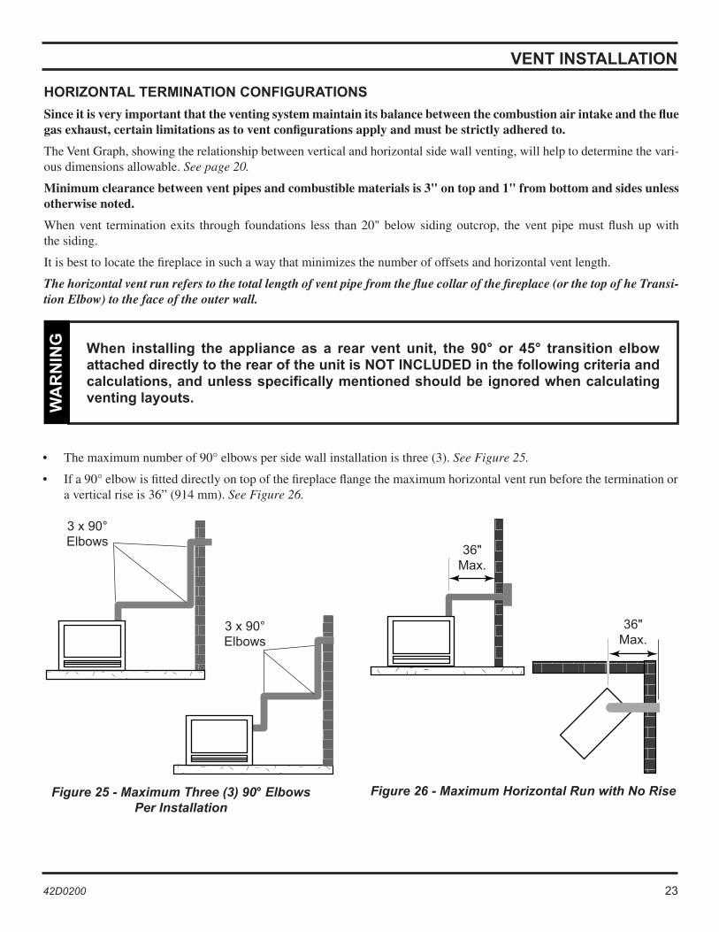
Figure 25 - Maximum Three (3) 90° Elbows Per Installation
• The maximum number of 90° elbows per side wall installation is three (3). See Figure 25.
• If a 90° elbow is fitted directly on top of the fireplace flange the maximum horizontal vent run before the termination or a vertical rise is 36” (914 mm). See Figure 26.
Figure 26 - Maximum Horizontal Run with No Rise
3 x 90°Elbows
3 x 90°Elbows
36"Max.
36"Max.
24 42D0200 42D0200 25
���
����
��� �
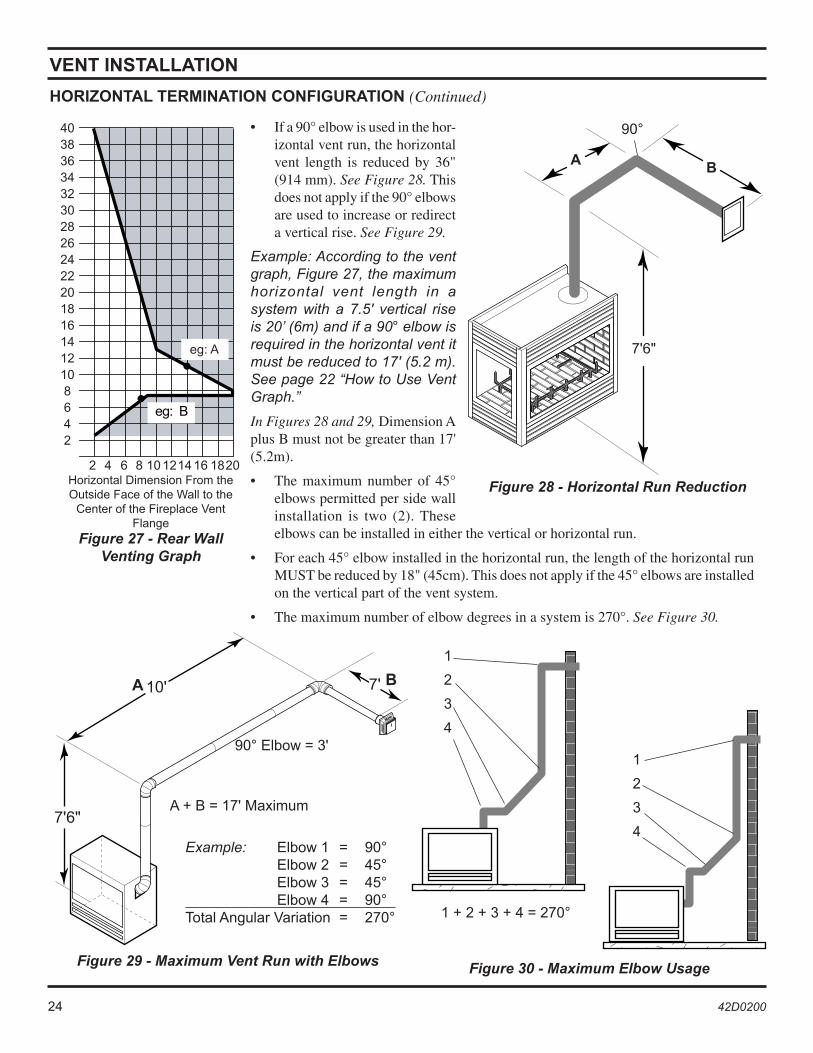
• If a 90° elbow is used in the hor-izontal vent run, the horizontal vent length is reduced by 36" (914 mm). See Figure 28. This does not apply if the 90° elbows are used to increase or redirect a vertical rise. See Figure 29.
Example: According to the vent graph, Figure 27, the maximum horizontal vent length in a system with a 7.5' vertical rise is 20’ (6m) and if a 90° elbow is required in the horizontal vent it must be reduced to 17' (5.2 m). See page 22 “How to Use Vent Graph.”
In Figures 28 and 29, Dimension A plus B must not be greater than 17' (5.2m).
• The maximum number of 45° elbows permitted per side wall installation is two (2). These elbows can be installed in either the vertical or horizontal run.
• For each 45° elbow installed in the horizontal run, the length of the horizontal run MUST be reduced by 18" (45cm). This does not apply if the 45° elbows are installed on the vertical part of the vent system.
• The maximum number of elbow degrees in a system is 270°. See Figure 30.
Figure 29 - Maximum Vent Run with Elbows
Example: Elbow 1 = 90° Elbow 2 = 45° Elbow 3 = 45° Elbow 4 = 90°Total Angular Variation = 270°
Figure 30 - Maximum Elbow Usage
VENT INSTALLATION
A + B = 17' Maximum
90° Elbow = 3'
1 + 2 + 3 + 4 = 270°
1
2
3
4
1
2
3
4
Figure 28 - Horizontal Run Reduction
90°
7'6"
A B
������������������������������������
� � � � �������� ����
��� �
Figure 27 - Rear Wall Venting Graph
Horizontal Dimension From the Outside Face of the Wall to the
Center of the Fireplace Vent Flange
HORIZONTAL TERMINATION CONFIGURATION (Continued)

24 42D0200 42D0200 25
VENT INSTALLATION
BELOW GRADE INSTALLATIONS
When it is not possible to meet the required vent terminal clearances of 12" above grade level, a snorkel kit is recommended. It allows installation depth down to 7" (178mm) below grade level. The 7" (178mm) is measured from the center of the horizontal vent pipe as it penetrates through the wall.
Ensure that sidewall venting clearances are observed. If venting system is installed below ground, we recommend a window well with adequate and proper drainage to be installed around the termination area.
If installing a snorkel, a minimum 24" vertical rise is necessary. The maximum horizontal run with the 24” vertical pipe is 36". This measurement is taken from the collar of the fireplace (or transition elbow) to the face of the exterior wall. See the Sidewall Venting Graph for extended horizontal run if the vertical exceeds 24".
1. Establish vent hole through the wall. See Figure 20, page 21.
2. Remove soil to a depth of approximately 16" below base of snorkel. Install drain pipe. Install window well (not supplied). Refill hole with 12" of coarse gravel leaving a clearance of approximately 4" below snorkel. See Figure 30.
3. Install vent system.
4. Ensure a watertight seal is made around the vent pipe coming through the wall.
5. Slide the snorkel into the vent pipes and secure to the wall.
6. Level the soil so as to maintain a 4" clearance below snorkel. See Figure 31.
• Do not back fill around snorkel.
• A clearance of at least 4" must be maintained between the snorkel and the soil.W
AR
NIN
G
If the foundation is recessed, use recess brackets (not supplied) for securing lower portion of the snorkel. Fasten brackets to wall first, then secure to snorkel with self drilling #8x1/2 sheet metal screws. It will be necessary to extend vent pipes out as far as the protruding wall face. See Figure 32.
Figure 32 - Snorkel Installation, Recessed FoundationFigure 31 - Below Grade Installation
Screws
Minimum 4" Clearance
Ground
Window Well
Gravel
Drain
Foundation Wall
Firestop
24"Minimum
FoundationRecess
Watertight Seal Around Pipe Sheet Metal
Screws
Wall Screws
Snorkel
26 42D0200 42D0200 27
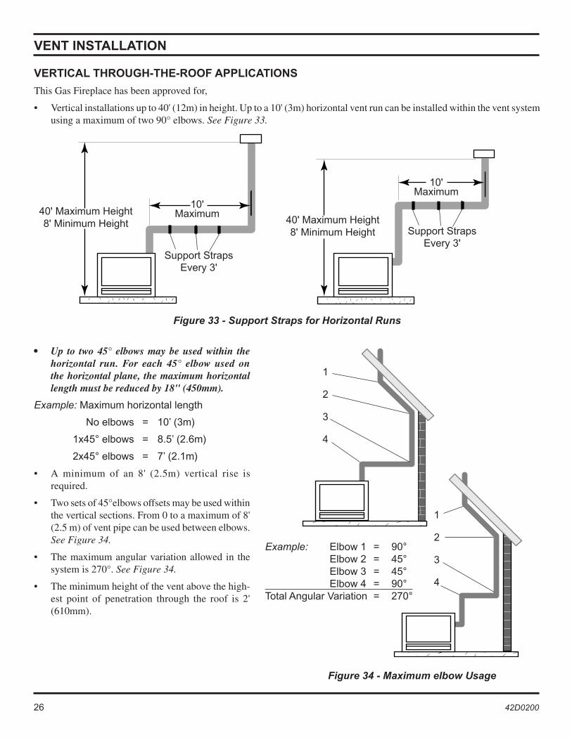
VERTICAL THROUGH-THE-ROOF APPLICATIONS
This Gas Fireplace has been approved for,
• Vertical installations up to 40' (12m) in height. Up to a 10' (3m) horizontal vent run can be installed within the vent system using a maximum of two 90° elbows. See Figure 33.
Figure 33 - Support Straps for Horizontal Runs
VENT INSTALLATION
Figure 34 - Maximum elbow Usage
• Up to two 45° elbows may be used within the horizontal run. For each 45° elbow used on the horizontal plane, the maximum horizontal length must be reduced by 18" (450mm).
Example: Maximum horizontal length
No elbows = 10’ (3m)
1x45° elbows = 8.5’ (2.6m)
2x45° elbows = 7’ (2.1m)
• A minimum of an 8' (2.5m) vertical rise is required.
• Two sets of 45°elbows offsets may be used within the vertical sections. From 0 to a maximum of 8' (2.5 m) of vent pipe can be used between elbows. See Figure 34.
• The maximum angular variation allowed in the system is 270°. See Figure 34.
• The minimum height of the vent above the high-est point of penetration through the roof is 2' (610mm).
40' Maximum Height8' Minimum Height 40' Maximum Height
8' Minimum Height
10'Maximum
10'Maximum
1
2
3
4
1
2
3
4
Support StrapsEvery 3'
Support StrapsEvery 3'
Example: Elbow 1 = 90° Elbow 2 = 45° Elbow 3 = 45° Elbow 4 = 90°Total Angular Variation = 270°
26 42D0200 42D0200 27
����������
VENT INSTALLATION
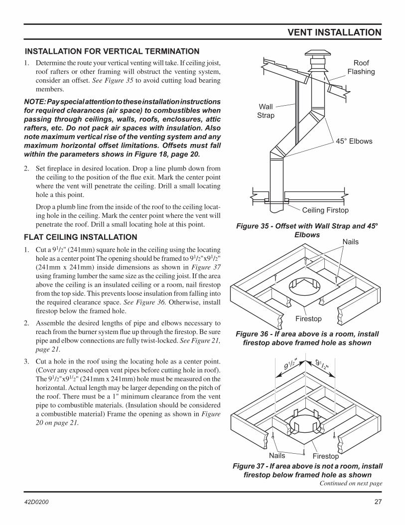
INSTALLATION FOR VERTICAL TERMINATION 1. Determine the route your vertical venting will take. If ceiling joist,
roof rafters or other framing will obstruct the venting system, consider an offset. See Figure 35 to avoid cutting load bearing members.
NOTE: Pay special attention to these installation instructions for required clearances (air space) to combustibles when passing through ceilings, walls, roofs, enclosures, attic rafters, etc. Do not pack air spaces with insulation. Also note maximum vertical rise of the venting system and any maximum horizontal offset limitations. Offsets must fall within the parameters shows in Figure 18, page 20.
2. Set fireplace in desired location. Drop a line plumb down from the ceiling to the position of the flue exit. Mark the center point where the vent will penetrate the ceiling. Drill a small locating hole a this point.
Drop a plumb line from the inside of the roof to the ceiling locat-ing hole in the ceiling. Mark the center point where the vent will penetrate the roof. Drill a small locating hole at this point.
FLAT CEILING INSTALLATION
1. Cut a 91/2" (241mm) square hole in the ceiling using the locating hole as a center point The opening should be framed to 91/2"x91/2" (241mm x 241mm) inside dimensions as shown in Figure 37 using framing lumber the same size as the ceiling joist. If the area above the ceiling is an insulated ceiling or a room, nail firestop from the top side. This prevents loose insulation from falling into the required clearance space. See Figure 36. Otherwise, install firestop below the framed hole.
2. Assemble the desired lengths of pipe and elbows necessary to reach from the burner system flue up through the firestop. Be sure pipe and elbow connections are fully twist-locked. See Figure 21, page 21.
3. Cut a hole in the roof using the locating hole as a center point. (Cover any exposed open vent pipes before cutting hole in roof). The 91/2"x91/2" (241mm x 241mm) hole must be measured on the horizontal. Actual length may be larger depending on the pitch of the roof. There must be a 1" minimum clearance from the vent pipe to combustible materials. (Insulation should be considered a combustible material) Frame the opening as shown in Figure 20 on page 21.
Figure 35 - Offset with Wall Strap and 45° Elbows
Roof Flashing
Wall Strap
45° Elbows
Ceiling Firstop
Figure 36 - If area above is a room, install firestop above framed hole as shown
Figure 37 - If area above is not a room, install firestop below framed hole as shown
Continued on next page
Firestop
Nails
Nails Firestop
28 42D0200 42D0200 29
VENT INSTALLATION
4. Connect a section of pipe and extend up through the hole.
NOTE: If an offset is needed to avoid obstructions, you must support the vent pipe every three (3) feet. Use wall straps for this purpose. See Figure 32, page 24. Whenever possible, use 45° elbows instead of 90° elbows. The 45° elbow offers less restriction to the flow of the flue gases and intake air.
5. Place the flashing over the pipe section(s) extending through the roof. Secure the base of the flashing to the roof and framing with roofing nails. Be sure roofing material overlaps the top edge of the flashing. There must be a 1" clearance from the vent pipe to combustible materials.
6. Continue to add pipe sections until the height of the vent cap meets the minimum building code requirements.
NOTE: You must increase vent height for steep roof pitches. Nearby trees, adjoining roof lines, steep pitched roofs, and other similar factors may cause poor draft or down-drafting in high winds. Increasing the vent height may solve this problem.
NOTE: If the vent pipe passes through any occupied areas above the first floor, including storage spaces and closets, you must enclose pipe. You may frame and sheetrock the enclosure with standard construction material. Make sure to meet the minimum allowable clearances to combustibles. Do not fill any of the required clearance spaces with insulation.
28 42D0200 42D0200 29
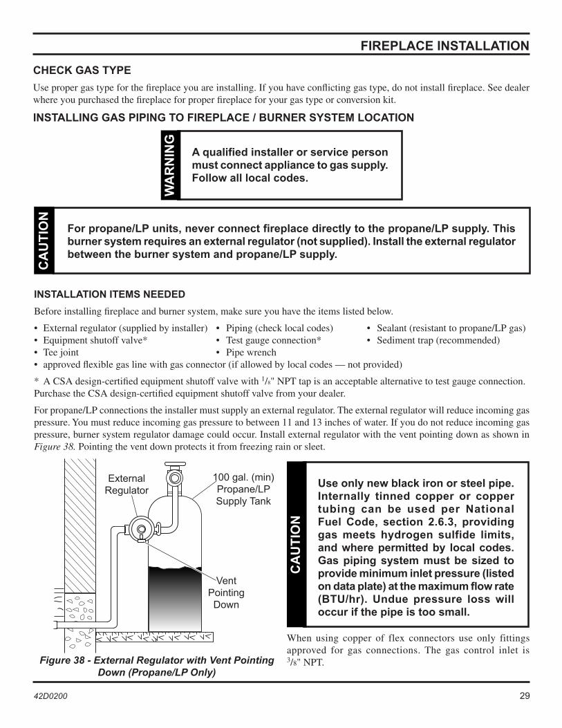
Figure 38 - External Regulator with Vent Pointing Down (Propane/LP Only)
Use only new black iron or steel pipe. Internally tinned copper or copper tubing can be used per National Fuel Code, section 2.6.3, providing gas meets hydrogen sulfide limits, and where permitted by local codes. Gas piping system must be sized to provide minimum inlet pressure (listed on data plate) at the maximum flow rate (BTU/hr). Undue pressure loss will occur if the pipe is too small.
CA
UT
ION
FIREPLACE INSTALLATION
CHECK GAS TYPE
Use proper gas type for the fireplace you are installing. If you have conflicting gas type, do not install fireplace. See dealer where you purchased the fireplace for proper fireplace for your gas type or conversion kit.
INSTALLING GAS PIPING TO FIREPLACE / BURNER SYSTEM LOCATION
For propane/LP units, never connect fireplace directly to the propane/LP supply. This burner system requires an external regulator (not supplied). Install the external regulator between the burner system and propane/LP supply.
CA
UT
ION
A qualified installer or service person must connect appliance to gas supply. Follow all local codes.
WA
RN
ING
INSTALLATION ITEMS NEEDED
Before installing fireplace and burner system, make sure you have the items listed below.
• External regulator (supplied by installer) • Piping (check local codes) • Sealant (resistant to propane/LP gas) • Equipment shutoff valve* • Test gauge connection* • Sediment trap (recommended) • Tee joint • Pipe wrench• approved flexible gas line with gas connector (if allowed by local codes — not provided)
* A CSA design-certified equipment shutoff valve with 1/8" NPT tap is an acceptable alternative to test gauge connection. Purchase the CSA design-certified equipment shutoff valve from your dealer.
For propane/LP connections the installer must supply an external regulator. The external regulator will reduce incoming gas pressure. You must reduce incoming gas pressure to between 11 and 13 inches of water. If you do not reduce incoming gas pressure, burner system regulator damage could occur. Install external regulator with the vent pointing down as shown in Figure 38. Pointing the vent down protects it from freezing rain or sleet.
External Regulator
100 gal. (min) Propane/LP Supply Tank
Vent Pointing Down
When using copper of flex connectors use only fittings approved for gas connections. The gas control inlet is 3/8" NPT.
30 42D0200 42D0200 31
�� �������
FIREPLACE INSTALLATION
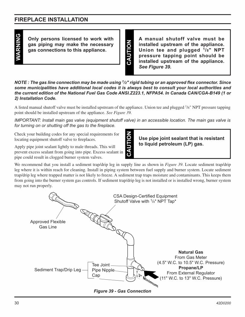
A listed manual shutoff valve must be installed upstream of the appliance. Union tee and plugged 1/8" NPT pressure tapping point should be installed upstream of the appliance. See Figure 39.
IMPORTANT: Install main gas valve (equipment shutoff valve) in an accessible location. The main gas valve is for turning on or shutting off the gas to the fireplace.
Check your building codes for any special requirements for locating equipment shutoff valve to fireplaces.
Apply pipe joint sealant lightly to male threads. This will prevent excess sealant from going into pipe. Excess sealant in pipe could result in clogged burner system valves.
A manual shutoff valve must be installed upstream of the appliance. Union tee and plugged 1/8" NPT pressure tapping point should be installed upstream of the appliance. See Figure 39.
CA
UT
ION
Use pipe joint sealant that is resistant to liquid petroleum (LP) gas.
CA
UT
ION
We recommend that you install a sediment trap/drip leg in supply line as shown in Figure 39. Locate sediment trap/drip leg where it is within reach for cleaning. Install in piping system between fuel supply and burner system. Locate sediment trap/drip leg where trapped matter is not likely to freeze. A sediment trap traps moisture and contaminants. This keeps them from going into the burner system gas controls. If sediment trap/drip leg is not installed or is installed wrong, burner system may not run properly.
Figure 39 - Gas Connection
Tee JointPipe NippleCap
Approved Flexible Gas Line
CSA Design-Certified Equipment Shutoff Valve with 1/8" NPT Tap*
Sediment Trap/Drip Leg
Natural GasFrom Gas Meter
(4.5" W.C. to 10.5" W.C. Pressure)Propane/LP
From External Regulator (11" W.C. to 13" W.C. Pressure)
NOTE : The gas line connection may be made using 1/2" rigid tubing or an approved flex connector. Since some municipalities have additional local codes it is always best to consult your local authorities and the current edition of the National Fuel Gas Code ANSI.Z223.1, NFPA54. In Canada CAN/CGA-B149 (1 or 2) Installation Code.
Only persons licensed to work with gas piping may make the necessary gas connections to this appliance.
WA
RN
ING
30 42D0200 42D0200 31
CHECKING GAS PRESSURE
1. Check gas type. The gas supply must be the same as stated on the appliance’s rating decal. If the gas supply is different from the fireplace, STOP! Do not install the appliance. Contact your dealer immediately.
2. To ease installation, a 30" (mm) flex line with manual shut-off valve has been provided with on this appliance. Install and attach 1/2" gas line onto shut-off valve.
3. After completing gas line connection, purge air from gas line and test all gas joints from the gas meter to the fireplace for leaks. Use a solution of 50/40 water and soap or a gas sniffer.
4. To adjust flame height, turn HI/LO knob to HI to get maximum pressure to burner. Turn HI/LO knob to LO to get minimum pressure.
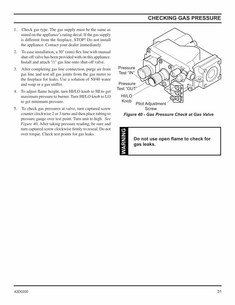
5. To check gas pressures at valve, turn captured screw counter clockwise 2 or 3 turns and then place tubing to pressure gauge over test point. Turn unit to high. See Figure 40. After taking pressure reading, be sure and turn captured screw clockwise firmly to reseal. Do not over torque. Check test points for gas leaks.
Do not use open flame to check for gas leaks.
WA
RN
ING
Figure 40 - Gas Pressure Check at Gas Valve
Pressure Test “IN”
Pressure Test “OUT”
HI/LO Knob
Pilot Adjustment Screw
32 42D0200 42D0200 33
ON
OFF
OPTIONAL REMOTEWALL SWITCH
ON
OFF
OPTIONAL REMOTEWALL SWITCH
PILOT HI
LO
ON
OFF
THTP
TH/TP
ONOFF
RS
REMOTE WALL MOUNTED SWITCH
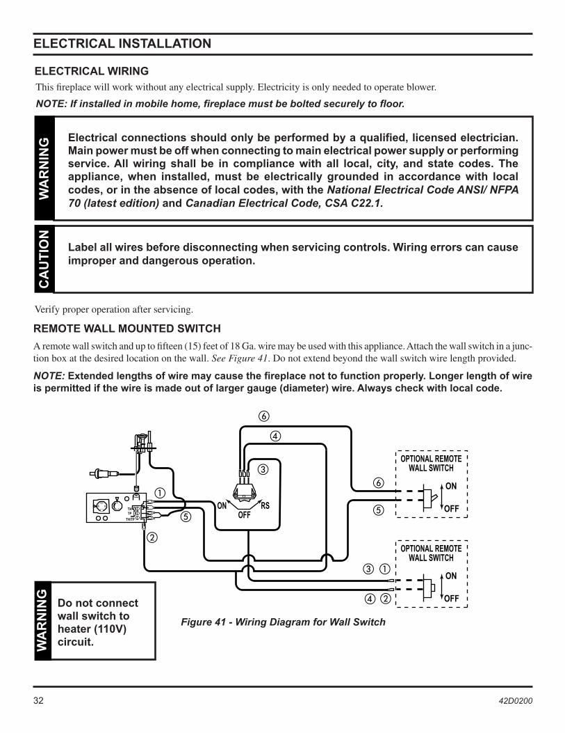
A remote wall switch and up to fifteen (15) feet of 18 Ga. wire may be used with this appliance. Attach the wall switch in a junc-tion box at the desired location on the wall. See Figure 41. Do not extend beyond the wall switch wire length provided.
NOTE: Extended lengths of wire may cause the fireplace not to function properly. Longer length of wire is permitted if the wire is made out of larger gauge (diameter) wire. Always check with local code.
Figure 41 - Wiring Diagram for Wall Switch
ELECTRICAL INSTALLATION
ELECTRICAL WIRING
Electrical connections should only be performed by a qualified, licensed electrician. Main power must be off when connecting to main electrical power supply or performing service. All wiring shall be in compliance with all local, city, and state codes. The appliance, when installed, must be electrically grounded in accordance with local codes, or in the absence of local codes, with the National Electrical Code ANSI/ NFPA 70 (latest edition) and Canadian Electrical Code, CSA C22.1.
WA
RN
ING
Label all wires before disconnecting when servicing controls. Wiring errors can cause improper and dangerous operation.
CA
UT
ION
Verify proper operation after servicing.
This fireplace will work without any electrical supply. Electricity is only needed to operate blower.
NOTE: If installed in mobile home, fireplace must be bolted securely to floor.
Do not connect wall switch to heater (110V) circuit. W
AR
NIN
G
32 42D0200 42D0200 33
GLASS REMOVAL
GLASS FRAME REMOVAL
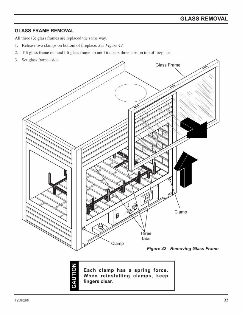
All three (3) glass frames are replaced the same way.
1. Release two clamps on bottom of fireplace. See Figure 42.
2. Tilt glass frame out and lift glass frame up until it clears three tabs on top of fireplace.
3. Set glass frame aside.
Figure 42 - Removing Glass Frame
Glass Frame
Three Tabs
Clamp
Each clamp has a spring force. When reinstalling clamps, keep fingers clear.
CA
UT
ION
Clamp
34 42D0200 42D0200 35
LOG PLACEMENT
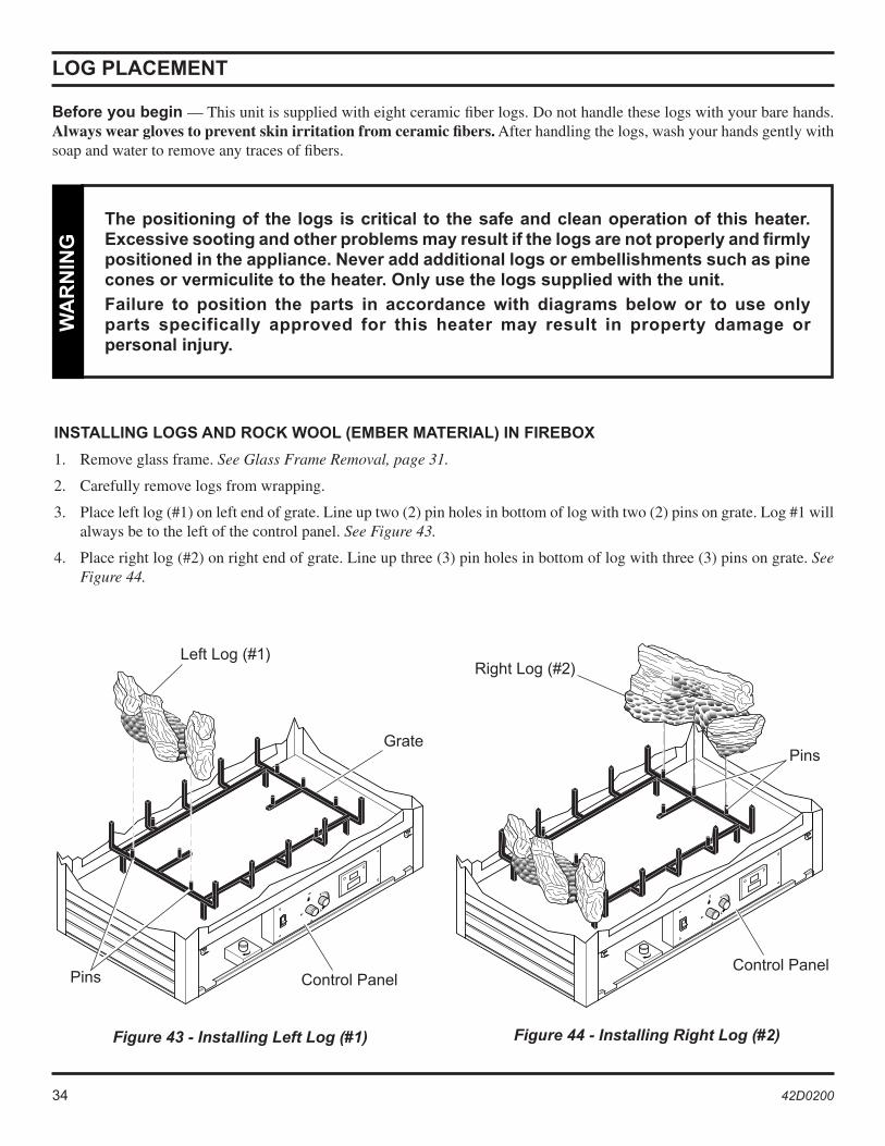
INSTALLING LOGS AND ROCK WOOL (EMBER MATERIAL) IN FIREBOX
1. Remove glass frame. See Glass Frame Removal, page 31.
2. Carefully remove logs from wrapping.
3. Place left log (#1) on left end of grate. Line up two (2) pin holes in bottom of log with two (2) pins on grate. Log #1 will always be to the left of the control panel. See Figure 43.
4. Place right log (#2) on right end of grate. Line up three (3) pin holes in bottom of log with three (3) pins on grate. See Figure 44.
Figure 43 - Installing Left Log (#1)
Before you begin — This unit is supplied with eight ceramic fiber logs. Do not handle these logs with your bare hands. Always wear gloves to prevent skin irritation from ceramic fibers. After handling the logs, wash your hands gently with soap and water to remove any traces of fibers.
The positioning of the logs is critical to the safe and clean operation of this heater. Excessive sooting and other problems may result if the logs are not properly and firmly positioned in the appliance. Never add additional logs or embellishments such as pine cones or vermiculite to the heater. Only use the logs supplied with the unit.
Failure to position the parts in accordance with diagrams below or to use only parts specifically approved for this heater may result in property damage or personal injury.
WA
RN
ING
Figure 44 - Installing Right Log (#2)
Left Log (#1)Right Log (#2)
Grate
Pins
Pins
Control Panel Control Panel
34 42D0200 42D0200 35
Continued on next page
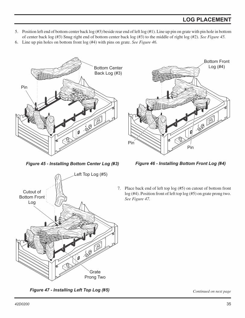
5. Position left end of bottom center back log (#3) beside rear end of left log (#1). Line up pin on grate with pin hole in bottom of center back log (#3) Snug right end of bottom center back log (#3) to the middle of right log (#2). See Figure 45.
6. Line up pin holes on bottom front log (#4) with pins on grate. See Figure 46.
LOG PLACEMENT
Figure 45 - Installing Bottom Center Log (#3) Figure 46 - Installing Bottom Front Log (#4)
Figure 47 - Installing Left Top Log (#5)
7. Place back end of left top log (#5) on cutout of bottom front log (#4). Position front of left top log (#5) on grate prong two. See Figure 47.
Bottom Center Back Log (#3)
Bottom Front Log (#4)
Pin
Left Top Log (#5)
Grate Prong Two
Cutout of Bottom Front
Log
Pin
Pin

36 42D0200 42D0200 37
Figure 48 - Installing Top Log (#6)
LOG PLACEMENT
8. Place Y-Shaped end of top log (#6) on on prong four of back of grate. Position other end of top log (#6) in cutout of bottom center log (#3). See Figure 48.
Figure 49 - Rock Wool Placement
9. Break up rock wool (ember material) into dime-sized pieces. Place evenly across burner surface and mesh of grate. See Figure 49. Do not exceed 1" depth of coverage.
Top Log #6 Cutout on
Bottom Center Log
Grate Prong Four
Rock Wool
Control Panel
36 42D0200 42D0200 37
AIR RESTRICTOR ADJUSTMENT
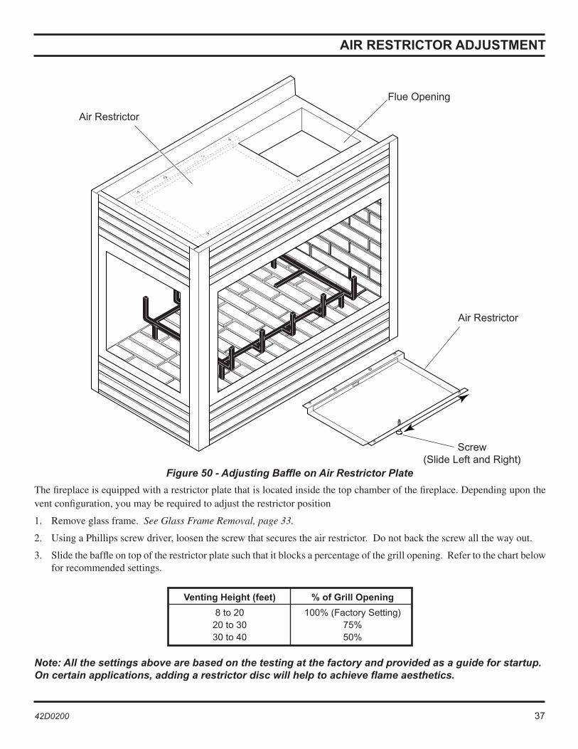
The fireplace is equipped with a restrictor plate that is located inside the top chamber of the fireplace. Depending upon the vent configuration, you may be required to adjust the restrictor position
1. Remove glass frame. See Glass Frame Removal, page 33.
2. Using a Phillips screw driver, loosen the screw that secures the air restrictor. Do not back the screw all the way out.
3. Slide the baffle on top of the restrictor plate such that it blocks a percentage of the grill opening. Refer to the chart below for recommended settings.
Venting Height (feet) % of Grill Opening
8 to 20 100% (Factory Setting) 20 to 30 75% 30 to 40 50%
Note: All the settings above are based on the testing at the factory and provided as a guide for startup. On certain applications, adding a restrictor disc will help to achieve flame aesthetics.
Air Restrictor
Screw(Slide Left and Right)
Figure 50 - Adjusting Baffle on Air Restrictor Plate
Flue Opening
Air Restrictor
38 42D0200 42D0200 39
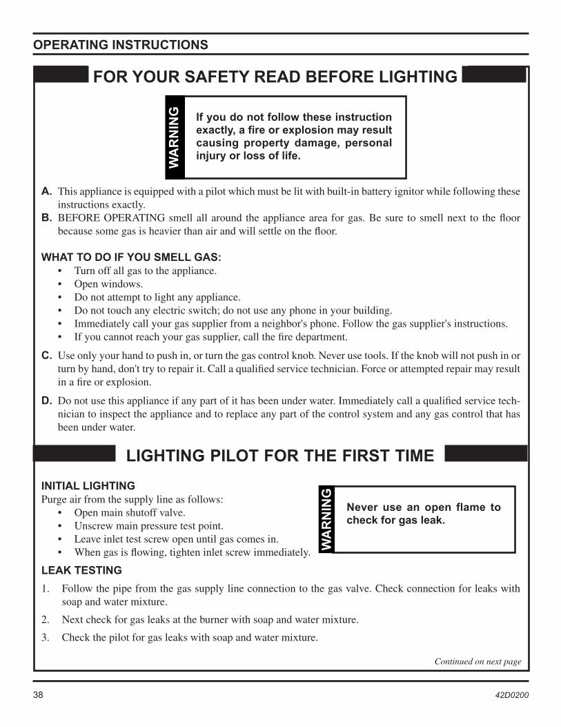
A. This appliance is equipped with a pilot which must be lit with built-in battery ignitor while following these instructions exactly.
B. BEFORE OPERATING smell all around the appliance area for gas. Be sure to smell next to the floor because some gas is heavier than air and will settle on the floor.
WHAT TO DO IF YOU SMELL GAS: • Turn off all gas to the appliance. • Open windows. • Do not attempt to light any appliance. • Do not touch any electric switch; do not use any phone in your building. • Immediately call your gas supplier from a neighbor's phone. Follow the gas supplier's instructions. • If you cannot reach your gas supplier, call the fire department.
C. Use only your hand to push in, or turn the gas control knob. Never use tools. If the knob will not push in or turn by hand, don't try to repair it. Call a qualified service technician. Force or attempted repair may result in a fire or explosion.
D. Do not use this appliance if any part of it has been under water. Immediately call a qualified service tech-nician to inspect the appliance and to replace any part of the control system and any gas control that has been under water.
OPERATING INSTRUCTIONS
If you do not follow these instruction exactly, a fire or explosion may result causing property damage, personal injury or loss of life.
WA
RN
ING
FOR YOUR SAFETY READ BEFORE LIGHTING
LIGHTING PILOT FOR THE FIRST TIME
INITIAL LIGHTING Purge air from the supply line as follows: • Open main shutoff valve. • Unscrew main pressure test point. • Leave inlet test screw open until gas comes in. • When gas is flowing, tighten inlet screw immediately.
LEAK TESTING
1. Follow the pipe from the gas supply line connection to the gas valve. Check connection for leaks with soap and water mixture.
2. Next check for gas leaks at the burner with soap and water mixture.
3. Check the pilot for gas leaks with soap and water mixture.
Never use an open flame to check for gas leak.
WA
RN
ING
Continued on next page
38 42D0200 42D0200 39
�����
����
���
�
��
OPERATING INSTRUCTIONS
APPROVED LEAK TESTING METHOD
You may check for gas leaks with the following methods only:
• Soap and water solution
• An approved leak testing spray
• Electronic sniffer
If using a soap and water solution to test for leaks, DO NOT spray solution onto control body.
WA
RN
ING
NOTE: Remove any excessive pipe compound from the connections. Excessive pipe compound can set off electronic sniffers.
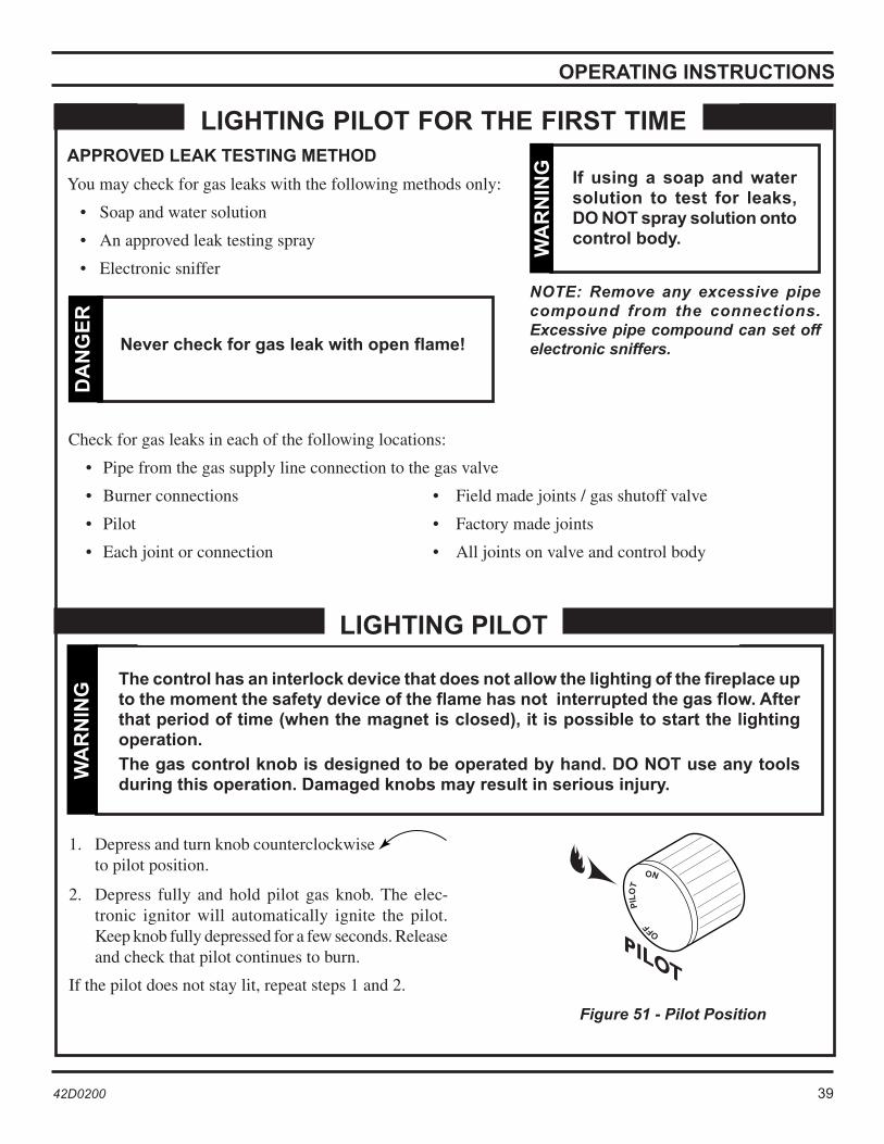
The control has an interlock device that does not allow the lighting of the fireplace up to the moment the safety device of the flame has not interrupted the gas flow. After that period of time (when the magnet is closed), it is possible to start the lighting operation.
The gas control knob is designed to be operated by hand. DO NOT use any tools during this operation. Damaged knobs may result in serious injury.
WA
RN
ING
1. Depress and turn knob counterclockwise to pilot position.
2. Depress fully and hold pilot gas knob. The elec-tronic ignitor will automatically ignite the pilot.Keep knob fully depressed for a few seconds. Release and check that pilot continues to burn.
If the pilot does not stay lit, repeat steps 1 and 2.
LIGHTING PILOT
Figure 51 - Pilot Position
Check for gas leaks in each of the following locations:
• Pipe from the gas supply line connection to the gas valve
• Burner connections • Field made joints / gas shutoff valve
• Pilot • Factory made joints
• Each joint or connection • All joints on valve and control body
Never check for gas leak with open flame!
DA
NG
ER
LIGHTING PILOT FOR THE FIRST TIME
40 42D0200 42D0200 41
T
�����
���
������
�
���
�����
��
�����Figure 53 - On Position
�����
����
���
�
��
Figure 52 - On/Off/RS Switch
�����
��
OPERATING INSTRUCTIONS
LIGHTING BURNER MAIN BURNER SWITCH
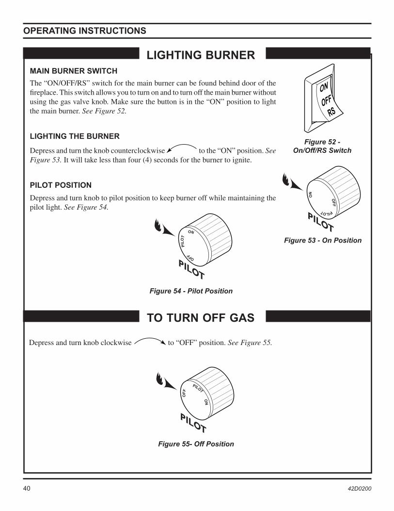
The “ON/OFF/RS” switch for the main burner can be found behind door of the fireplace. This switch allows you to turn on and to turn off the main burner without using the gas valve knob. Make sure the button is in the “ON” position to light the main burner. See Figure 52.
LIGHTING THE BURNER
Depress and turn the knob counterclockwise to the “ON” position. See Figure 53. It will take less than four (4) seconds for the burner to ignite.
PILOT POSITION
Depress and turn knob to pilot position to keep burner off while maintaining the pilot light. See Figure 54.
Depress and turn knob clockwise to “OFF” position. See Figure 55.
TO TURN OFF GAS
Figure 55- Off Position
Figure 54 - Pilot Position
40 42D0200 42D0200 41
CLEANING AND MAINTENANCE
Clean the tempered glass periodically. Condensation will some-times form on the glass during a cold startup. This is normal for all gas fireplaces. This condensation often attracts dust and lint to the surface of the glass. The initial paint curing of the appliance can also leave a slight film on the glass.
Your should clean the glass after the first two weeks of use. After that, you should clean the glass no more than two or three times a season. Use a mild glass cleaner to clean the door. Do not use abrasive cleaners. They will damage the glass surface.
PILOT AND BURNER FLAMES
Let glass cool before cleaning. Do not clean glass when it is hot. Damage could occur.
CA
UT
ION
Make sure the gas valve knob is in the “OFF” position. Wait at least five (5) minutes before starting maintenance. Fireplace must be cold before starting maintenance.
VENTING SYSTEM
A qualified agency should examine the venting system annually.
CLEANING GLASS
Make sure clearances to combus-tibles leave room for maintenance and service.
WA
RN
ING
Carefully reassemble and reseal fireplace properly after any cleaning or servicing.
WA
RN
ING
FIREBOX CLEANING
1. Carefully remove log set, and embers (rock wool) from combus-tion chamber.
2. Vacuum burner compartment thoroughly.
3. Vacuum or brush with soft brush any dust off logs.
4. Remove any lint from main burner and pilot.
5. Carefully replace log set, and embers in their correct positions. See pages 34 through 36.
6. Replace door (if it has been removed).
7. Relight pilot. See page 40.
8. Turn on main burner.
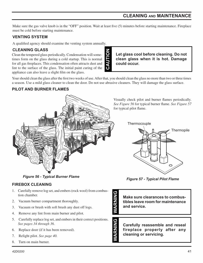
Figure 56 - Typical Burner Flame Figure 57 - Typical Pilot Flame
Thermopile
Thermocouple
Visually check pilot and burner flames periodically. See Figure 56 for typical burner flame. See Figure 57 for typical pilot flame.
42 42D0200 42D0200 43
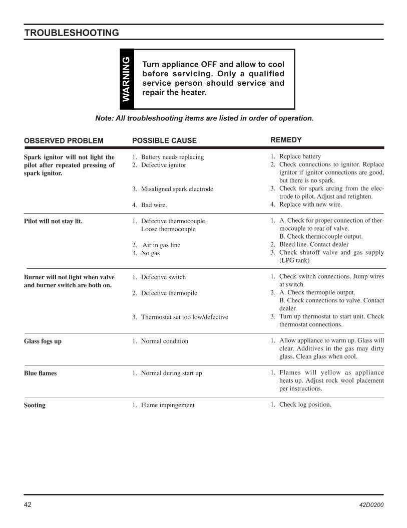
OBSERVED PROBLEM
Spark ignitor will not light the pilot after repeated pressing of spark ignitor.
Pilot will not stay lit.
Burner will not light when valve and burner switch are both on.
Glass fogs up
Blue flames
Sooting
POSSIBLE CAUSE
1. Battery needs replacing 2. Defective ignitor
3. Misaligned spark electrode
4. Bad wire.
1. Defective thermocouple. Loose thermocouple
2. Air in gas line3. No gas
1. Defective switch
2. Defective thermopile
3. Thermostat set too low/defective
1. Normal condition
1. Normal during start up
1. Flame impingement
REMEDY
1. Replace battery2. Check connections to ignitor. Replace
ignitor if ignitor connections are good, but there is no spark.
3. Check for spark arcing from the elec-trode to pilot. Adjust and retighten.
4. Replace with new wire.
1. A. Check for proper connection of ther-mocouple to rear of valve.
B. Check thermocouple output. 2. Bleed line. Contact dealer 3. Check shutoff valve and gas supply
(LPG tank)
1. Check switch connections. Jump wires at switch.
2. A. Check thermopile output. B. Check connections to valve. Contact
dealer. 3. Turn up thermostat to start unit. Check
thermostat connections.
1. Allow appliance to warm up. Glass will clear. Additives in the gas may dirty glass. Clean glass when cool.
1. Flames will yellow as appliance heats up. Adjust rock wool placement per instructions.
1. Check log position.
Note: All troubleshooting items are listed in order of operation.
TROUBLESHOOTING
WA
RN
ING
Turn appliance OFF and allow to cool before servicing. Only a qualified service person should service and repair the heater.
WA
RN
ING
42 42D0200 42D0200 43
120 VACBlower
120 VACSpeed Control
Green Green
Attach Blower to T-Stat
BlackBlack
Black
White
Blower Plug
Junction Box
ON/OFF Wall Switch orOptional Variable Speed Switch
120 VAC60Hz
Factory SuppliedNot Supplied
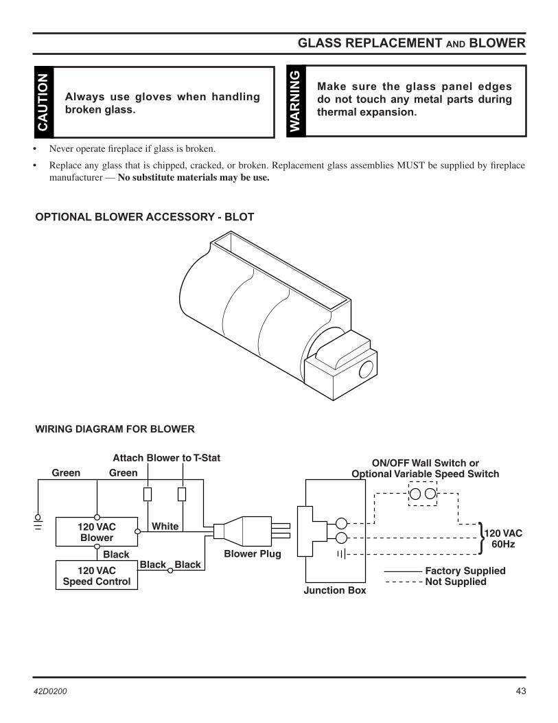
GLASS REPLACEMENT AND BLOWER
• Never operate fireplace if glass is broken.
• Replace any glass that is chipped, cracked, or broken. Replacement glass assemblies MUST be supplied by fireplace manufacturer — No substitute materials may be use.
Always use gloves when handling broken glass.
CA
UT
ION
Make sure the glass panel edges do not touch any metal parts during thermal expansion.
WA
RN
ING
OPTIONAL BLOWER ACCESSORY - BLOT
WIRING DIAGRAM FOR BLOWER

44 42D0200 42D0200 45
��
��
��
��
� �
�
�
�
�� � � �������������������������������
��
��
��
����
��
��
��
��
��
��
�
REPLACEMENT PARTS
44 42D0200 42D0200 45
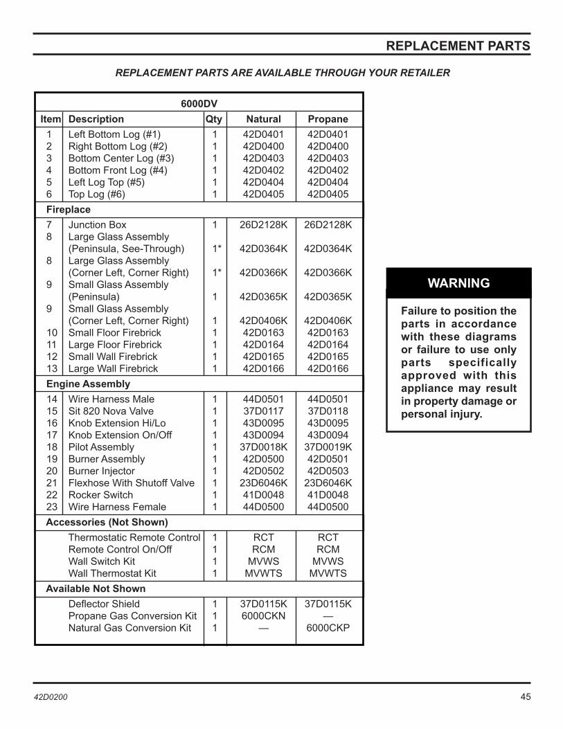
REPLACEMENT PARTS ARE AVAILABLE THROUGH YOUR RETAILER
REPLACEMENT PARTS
6000DV
Item Description Qty Natural Propane
1 Left Bottom Log (#1) 1 42D0401 42D0401 2 Right Bottom Log (#2) 1 42D0400 42D0400 3 Bottom Center Log (#3) 1 42D0403 42D0403 4 Bottom Front Log (#4) 1 42D0402 42D0402 5 Left Log Top (#5) 1 42D0404 42D0404 6 Top Log (#6) 1 42D0405 42D0405
Fireplace
7 Junction Box 1 26D2128K 26D2128K 8 Large Glass Assembly (Peninsula, See-Through) 1* 42D0364K 42D0364K 8 Large Glass Assembly (Corner Left, Corner Right) 1* 42D0366K 42D0366K 9 Small Glass Assembly (Peninsula) 1 42D0365K 42D0365K 9 Small Glass Assembly (Corner Left, Corner Right) 1 42D0406K 42D0406K 10 Small Floor Firebrick 1 42D0163 42D0163 11 Large Floor Firebrick 1 42D0164 42D0164 12 Small Wall Firebrick 1 42D0165 42D0165 13 Large Wall Firebrick 1 42D0166 42D0166
Engine Assembly
14 Wire Harness Male 1 44D0501 44D0501 15 Sit 820 Nova Valve 1 37D0117 37D0118 16 Knob Extension Hi/Lo 1 43D0095 43D0095 17 Knob Extension On/Off 1 43D0094 43D0094 18 Pilot Assembly 1 37D0018K 37D0019K 19 Burner Assembly 1 42D0500 42D0501 20 Burner Injector 1 42D0502 42D0503 21 Flexhose With Shutoff Valve 1 23D6046K 23D6046K 22 Rocker Switch 1 41D0048 41D0048 23 Wire Harness Female 1 44D0500 44D0500
Accessories (Not Shown)
Thermostatic Remote Control 1 RCT RCT Remote Control On/Off 1 RCM RCM Wall Switch Kit 1 MVWS MVWS Wall Thermostat Kit 1 MVWTS MVWTS
Available Not Shown
Deflector Shield 1 37D0115K 37D0115K Propane Gas Conversion Kit 1 6000CKN — Natural Gas Conversion Kit 1 — 6000CKP
Failure to position the parts in accordance with these diagrams or failure to use only parts specifically approved with this appliance may result in property damage or personal injury.
WARNING
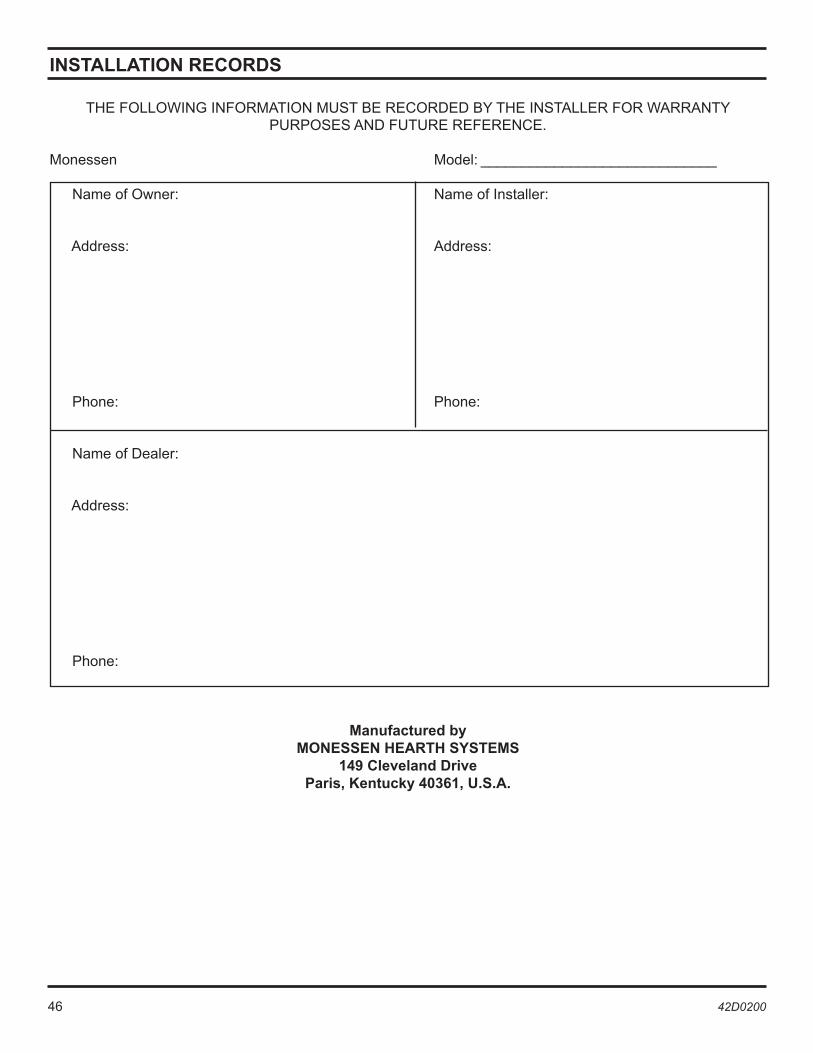
46 42D0200 42D0200 47
INSTALLATION RECORDS
THE FOLLOWING INFORMATION MUST BE RECORDED BY THE INSTALLER FOR WARRANTY PURPOSES AND FUTURE REFERENCE.
Monessen Model: _____________________________
Name of Owner: Name of Installer:
Address: Address:
Phone: Phone:
Name of Dealer:
Address:
Phone:
Manufactured byMONESSEN HEARTH SYSTEMS
149 Cleveland DriveParis, Kentucky 40361, U.S.A.

46 42D0200 42D0200 47
NOTES
February 2003 P/N 42D0200 • Rev. 3
LIMITED LIFETIME WARRANTY POLICY
LIFETIME WARRANTYThe following components are warranted for life to the original owner, subject of proof of purchase: Firebox, Combustion Chamber, Heat Exchanger, Grate, and Stainless Steel Burners.
FIVE YEAR WARRANTYThe following components are warranted for 5 years to the original owner, subject of proof of purchase: Vent Free Ceramic Fiber Logs, Catalytic Filter and Aluminized Burners.
BASIC WARRANTYMonessen Hearth Systems (MHS) warrants the components and materials in your gas appliance to be free from manufacturing and material defects for a period of two years from date of installation. After installation, if any of the components manufactured by MHS in the appliance are found to be defective in materials or workmanship, MHS will, at its option, replace or repair the defective components at no charge to the original owner. MHS will also pay for reasonable labor costs incurred in replacing or repairing such components for a period of two years from the date of installation. Any products presented for warranty repair must be accompanied by a dated proof of purchase.
This Limited Lifetime Warranty will be void if the appliance is not installed by a qualified installer in accordance with the installation instructions. The Limited Lifetime Warranty will also be void if the appliance is not operated and maintained according to the operating instructions supplied with the appliance, and does not extend to (1) firebox/burner assembly damage by accident, neglect, misuse, abuse, alteration, negligence of others, including the installation thereof by unqualified installers, (2) the costs of removal, reinstallation or transportation of defec-tive parts on the appliance, or (3) incidental or consequential damage. All service work must be performed by an authorized service representative.
This warranty is expressly in lieu of other warranties, express or implied, including the warranty of merchant-ability of fitness for purpose and of all other obligations or liabilities. Monessen Hearth Systems, Inc. does not assume for it any other obligations or liability in connection with the sale or use of the appliance. In states that do not allow limitations on how long an implied warranty lasts, or do not allow exclusion of indirect damage, those limitations of exclusions may not apply to you. You may also have additional rights not covered in this Limited Lifetime Warranty.
MHS reserves the right to investigate any and all claims against the Limited Lifetime Warranty and decide upon method of settlement.
For information about this warranty, contact:
Technical Services Monessen Hearth Systems 149 Cleveland Drive Paris, Kentucky 40361